EP1458232B1 - Vorrichtung für die fütterung von geflügel, insbesondere mastgeflügel, vorzugsweise broiler - Google Patents
Vorrichtung für die fütterung von geflügel, insbesondere mastgeflügel, vorzugsweise broiler Download PDFInfo
- Publication number
- EP1458232B1 EP1458232B1 EP02798266A EP02798266A EP1458232B1 EP 1458232 B1 EP1458232 B1 EP 1458232B1 EP 02798266 A EP02798266 A EP 02798266A EP 02798266 A EP02798266 A EP 02798266A EP 1458232 B1 EP1458232 B1 EP 1458232B1
- Authority
- EP
- European Patent Office
- Prior art keywords
- cylinder
- feed
- outside
- feeding
- outer cylinder
- Prior art date
- Legal status (The legal status is an assumption and is not a legal conclusion. Google has not performed a legal analysis and makes no representation as to the accuracy of the status listed.)
- Expired - Lifetime
Links
Images




Classifications
-
- A—HUMAN NECESSITIES
- A01—AGRICULTURE; FORESTRY; ANIMAL HUSBANDRY; HUNTING; TRAPPING; FISHING
- A01K—ANIMAL HUSBANDRY; AVICULTURE; APICULTURE; PISCICULTURE; FISHING; REARING OR BREEDING ANIMALS, NOT OTHERWISE PROVIDED FOR; NEW BREEDS OF ANIMALS
- A01K39/00—Feeding or drinking appliances for poultry or other birds
- A01K39/01—Feeding devices
- A01K39/012—Feeding devices filling automatically, e.g. by gravity from a reserve
- A01K39/0125—Panfeeding systems; Feeding pans therefor
-
- A—HUMAN NECESSITIES
- A01—AGRICULTURE; FORESTRY; ANIMAL HUSBANDRY; HUNTING; TRAPPING; FISHING
- A01K—ANIMAL HUSBANDRY; AVICULTURE; APICULTURE; PISCICULTURE; FISHING; REARING OR BREEDING ANIMALS, NOT OTHERWISE PROVIDED FOR; NEW BREEDS OF ANIMALS
- A01K39/00—Feeding or drinking appliances for poultry or other birds
- A01K39/01—Feeding devices
Definitions
- the invention relates to a device for the Feeding of kept free in a stable Poultry, especially poultry, preferably broiler, with at least one raised above the floor of the stable and Lowerable feed conveyor tube containing a number of Branch openings has, each one on the conveyor pipe is associated with hanging shell device, which is one of the branch opening outgoing downpipe and one below the Downpipe located feed bowl with spoke-like extending grating bars formed shell dome , wherein the downpipe from one of the Branch opening outgoing inner cylinder and a the Inner cylinder enclosing outer cylinder is made on the the feeding bowl by means of the bars of their Shell dome is hanging so that they lowered Feeding conveyor tube touches, in particular on the bottom of the Stalls touches down, the outer cylinder on the Inner cylinder is rotatable and guided raised and lowered and at least one limiting the lifting and lowering path Hub stop is provided.
- a device of the type described above is in the EP 0 105 571 B1.
- the placement of the Feed bowl used with lowered feed tube release further openings in the downpipe.
- the over the downpipe in the Feed shell reaching forage different bulk cones or Schüttnchn assigned.
- the feeding level can be in the shell but also set lower again because ultimately growing and therefore bigger Expecting animals also lower lying areas in the Feeding bowl for food intake problem-free as a chick reachable.
- Food bowls should be cleaned at regular intervals become. This is done by spraying with water, mostly after a fattening period, before the stable with new chicks is occupied.
- the feed bowl around the longitudinal axis of the Feeding tube outgoing downpipe can rotate because while virtually all interior areas of the feed bowl one directed from one side into the feeding bowl passing a sharp stream of water. Is the Rotating possibility of the feed bowl on the inner cylinder of the Downpipe still beneficial for cleaning, it is for reasons described above for the freedom of the additional openings in the downer still disadvantageous.
- the invention is based on the object, these disadvantages in a device for feeding poultry, as they are described at the beginning, to avoid.
- the gap area between two cylinder sections of the Inner cylinder or the outer cylinder forms one here also present as a so-called "360 ° - window” additional opening for the emergence of feed in the Feeding bowl, which is next to the lower free end of the Inner cylinder and outer cylinder formed downpipe is available.
- Each gap area between the cylinder sections forms a free-rotating opening, the only interrupted by the bridge organs.
- a drag chain or a Spiral is designed according to the invention Device ensures that each feed tray to the Preset food level also safe with feed is filled. A blanketing of individual food trays especially in the critical early stage of the fattening period for still small chicks due to blockages in the Area of additional openings in the downpipe, hardly comes still ahead.
- the usually vertical and thus parallel to the bottom of the Stalls extending feed conveyor tube can, for. B. by means centrally operated cables, to be moved vertically.
- the known device allows this operation that the feeding bowl can be put in positions, in which they are either placed on the floor of the stable or lifted off.
- the inventive Device putting the food bowl on the ground of the stall used to vertical the outer cylinder to Move inner cylinder and through this Displacement an additional feed discharge opening, namely the 360 ° encircling window in the downpipe too to open.
- At least one stroke stop is provided.
- the device according to the invention is at the formation the stroke of the outer cylinder a recess of his Cylinder inner surface involved, as well as at least one radially projecting from the inner cylinder support shoulder for the process. If the inner cylinder is raised by the Feed conveyor tube at a greater distance to the bottom of the Stalls is brought, the inner cylinder slides first in the outer cylinder to the protruding from the inner cylinder Support shoulder to the through the recess in the outer cylinder formed stage strikes, so that upon further increase of the inner cylinder, the outer cylinder and thus the with associated feeding bowl can be dragged.
- Each overlay shoulder for the recess can be any one Be inner cylinder arranged projection.
- Preferably every shoulder for the recess is part of one collar flange-like radial projection of the inner cylinder.
- each bridging member is a flat bar, whose Web surface plane radially to the axis of the respective inner or outer cylinder runs.
- the number of flat bars can be varied.
- Four flat bars for the Inner cylinder and seven flat bars for the outer cylinder have proven themselves.
- the as Flat bar present bridge organs of the outer cylinder the shape of radially over the periphery of the outer cylinder in the feed bowl projecting paddles or Wings open. Control the wings on the outer cylinder and get the even feed distribution in the Feeding dish, even if the entire feed bowl around the conveyor tube should oscillate or oscillate and prevent further excessive scratching and pawing of the animals in the feed and thus the resulting Feed losses.
- the feed should be as even as possible from the downpipe be handed out and distributed. There is an overflow of the feed from the feed bowl by a too high Avoid feeding level as well as eating the Animals aggravating, too low feed level.
- the training and especially the Compliance with a predetermined cone in the Feed bowl relevant, the bulk cone itself in turn can be influenced by the distance between Downpipe existing feed outlets and the Food bowl.
- the distance of the feed bowl from the bottom free end of the downpipe or from the "360 ° - window" has thus significant influence on the feed level in the Shell and from the feed level, it is in turn dependent on whether Feed intake by the animals run optimally.
- a Adjustment or adjustment of the distance between the feed bowl and the lower free end or between the feeding bowl and the "360 ° window" of the downpipe is advantageous and is in the inventive Device constructively realized by the Outer surface of an upper cylinder portion of Outer cylinder is designed as a threaded spindle, and that the free ends of the bars of the shell dome a screw ring are connected to the as Threaded spindle formed area of the outer cylinder screwed.
- the pitch of the threaded spindle is preferably such chosen that already at relatively low rotation or Angular movement of the feed bowl a noticeable Change in the distance between feed bowl and the Feed pipe, from which the downpipe with its Branches branches, noticeable.
- the food trays begin to feed a cleaning under a stream of water around a vertical axis to turn. This turning is even desirable.
- rotational movement has the disadvantage that thereby the adjusted feed level may change unintentionally. After cleaning all food trays of the Feeding line in a stable thus newly adjusted which involves a considerable amount of work.
- the automatic unwanted adjustment or rotation the feed bowls is in the inventive Device thereby prevents them from having at least one the rotation of the outer cylinder relative to the inner cylinder preventing but at least limiting rotation stop having.
- each rotation stop at least one in a predetermined Area of the outer surface of the inner cylinder arranged Collection has at least one at the Inner surface of the outer cylinder located driver, or projection, in which upon rotation of the outer cylinder The elevation running around the inner cylinder protrudes. Turns the food bowl and thus the Outer cylinder, on which the feed bowl hangs, opposite the inner cylinder, the projection beats at the latest Returning a predetermined rotational path to the survey and locks a further rotation.
- the projection is in the effective range of the upper one Head section of the inner cylinder existing survey, which in projects the rotational path of the projection on the outer cylinder.
- the feed bowl is thus in the upper position only so far rotatable until the rotational movement is stopped by the rotation stop.
- the device according to the invention is also still outstanding characterized by the fact that the independent, uncontrolled and thus opposite unwanted rotation of the screw ring the outer cylinder, with the result of an adjustment of the Feeding levels in the feed bowl, thereby preventing is that the outer cylinder in his as a threaded spindle trained area at least one elastic, preferably spring-elastic in the radial direction Has locking cams, with recesses, which the Having a screw ring on its inner circumferential surface, can be positively locked.
- the rotation stop in conjunction with the terms of diameter offset areas of the inner cylinder serves to the above-described adjustment of the feed level, if necessary against unintentional operation by means of Locking cams in the hanging position or optionally in the raised position of the shell release.
- Locking cams and the recesses with an angle to Rotary movement about the vertical axis aligned casserole edges are provided.
- the locking cams and the recesses with oblique to are provided with rotational movement aligned casserole flanks, are the elastic locking cams at appropriate Force applied during twisting and deflected in a camshaft similar manner from the Recesses steered.
- the threaded ring on the thread the outer cylinder are rotated further, with the the feedstuff position predetermining the lining of the forage such as described above changes.
- the locking cams a have reached adjacent recess, they snap into this Recess again or it can be the screw ring, under Repetition of the deflection, to be further rotated.
- the feeding bowl may be suitable for carrying of cleanings in the hanging position of the Turn the outer cylinder freely on the inner cylinder.
- the unit of feed bowl, dome and outer cylinder thus raise first. Subsequently, this unit can order the vertical axis in the direction of rotation of the desired change in the Food stand as long as twisted, in the form of Vosprüngen present driver on the outer cylinder the Have reached elevations on the inner cylinder and the Outer cylinder is secured against further rotation. In the continuation of the rotary motion, with increasing Force, the locking cams the feedstand positions free to return to the after a predetermined rotation to be able to snap into the next food stand position.
- the connecting organs can a hinged joint and at least one locking or Have holding element.
- the feeding plate can be in the area of his Tellerrandes also formed from two Tellerrandabêten one of which is attached to the bars of the cupola is connected and which has at least one hinged joint and at least one locking or holding element, e.g. B. Braces, are interconnected.
- a aushakbares folding joint so that a Futterteller could possibly be replaced.
- the feeding plate is cone-shaped in the middle worked out so that from the downpipe forming Unit of inner cylinder and outer cylinder in the Feeding dish falling chuck slip outwards can.
- each feeding section consists of at least one bag, a field or the like Deepening or collection of defined indentation.
- the screw ring For example, on the inner circumference of the screw ring seven recesses arranged so determine themselves thereby seven feed stand positions, which by twisting set the screw ring relative to the outer cylinder can be.
- the outer cylinder itself points in his Threaded area at least one, preferably two Locking cams on so on the circumference of the outer cylinder that they are simultaneously assigned in each case Recesses of the screw ring can engage.
- the device for feeding in a stable Free-roasted fattening poultry, especially broilers consists of at least one above the floor of the stable Can be raised and lowered held feed conveyor tube 1, the over the entire stable length runs and with one in it located conveyor spiral or a rope or chain with Shakers pourable feed to individual at the Feed conveyor tube 1 hanging shell devices 2 transported.
- the above parts can in their Entity can also be referred to as feed line.
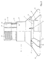
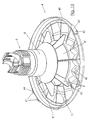
- Fig. 1 is only a part of the feed conveyor tube. 1 with one in the area of a branch opening in Feed conveyor tube 1 hanging shell device 2 shown.
- the tray device 2 comprises one of the here not further visible branch opening outgoing Downpipe 3 and one located under the downpipe 3 Feed bowl 4 with spoke-like running Bars 5 formed cupola 6. It exists the downpipe 3 from one of the not visible here Branch opening outgoing inner cylinder 7 and a the Inner cylinder 7 enclosing outer cylinder 8 at the Shell 4 by means of the bars 5 of their shell dome. 6 so depends that it is lowered in feed conveyor tube. 1 especially not on this one shown bottom 34 of the stall touches down.
- Of the Outer cylinder 8 is rotatable on the inner cylinder 7 as well raised and lowered guided, wherein at least one of the lifting and Senkweg limiting stroke stop is provided, the will be described in more detail below.
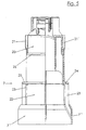
- FIG. 2 shows a view of the outer cylinder 8.
- FIG. 3 is a side view of the outer cylinder. 8 shown in a half section in FIG. 2.
- the outer cylinder 8 consists of adjacent ones mutually coaxial cylinder sections 8 'and 8' '.
- the Cylinder sections 8 'and 8' ' are interconnected over bridge organs 9, each of which is referred to as the Periphery of the outer cylinder 8 in the feed bowl. 4 protruding paddle or formed as a wing 10 is.
- the bridge members 9 bridge the gap area 11, the distance between the cylinder sections 8 'and 8 '' of the outer cylinder 8 corresponds.
- the cylinder inner surface 12 of the outer cylinder 8, or here his upper cylinder section 8 ' has a recess 13, which is part of a stroke stop 14.
- the outer surface of the upper cylinder portion 8 'of the outer cylinder 8 is in upper end portion formed as a threaded spindle 15, the Threads 16 has.
- the outer cylinder is made of suitable plastic, so that the threads 16 and thus the threaded spindle 15th easily in the production of the outer cylinder. 8 can be formed.
- FIG. 1 also shows, the free ends of Grating bars 5 of the shell dome 6 to a screw ring 17th connected to the threaded spindle as the 15th formed portion of the cylinder portion 8 'of the Outer cylinder 8 is screwed.
- the threaded spindle 15 causes an adjustment of the Feed bowl 4 in terms of height to the lower end the cylinder portion 8 "with the wings 10 of the Outer cylinder 8.
- Figures 2 and 3 can be further seen that a the rotation of the outer cylinder 8 relative to the Inner cylinder 7 limiting rotation stop on here the inner surface 18 of the outer cylinder 8 located Driver 19 has, in which during rotation of the Outer cylinder 8 executed around the inner cylinder 7 around Drehweg the on the outer surface 20 of the inner cylinder. 7 arranged elevation 21 protrudes.
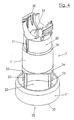
- Fig. 4 shows a view of the inner cylinder 7, the Cylinder sections 7 'and 7' ', wherein the open Gap area between the cylinder sections 7 'and 7 " again bridged by flattened bridge-shaped bridge members 23 becomes. 4, the part of the stroke stop 14 is visible, in the inner cylinder 7 as at least one radially from the Inner cylinder 7 projecting support shoulder 24 for the Recess 13 is formed in the outer cylinder 8.
- Fig. 4 illustrates that each support shoulder 24 for the Recess 13 Part of a collar flange-like radial projection 25 of the inner cylinder 7 is.
- Fig. 4 leaves also recognize that the outer surface 20 of the Inner cylinder 7 in the upper area, and thus in the area its head part, by means of reduced cylinder diameter opposite the remaining part of the cylinder portion 7 'of Inner cylinder 7 is discontinued.
- the deposition stage is denoted by 26.
- Fig. 2 reveals further that for securing against Rotation of the screw ring 17 (Fig. 1) with the Shell dome 6 and the feed bowl 4 existing Assembly, on each outer cylinder 8 in his than Threaded spindle 15 formed area two resilient locking cams 27 are provided.
- each Locking cam 27 is connected via a resilient strap 28 with connected to the outer cylinder 8.
- Fig. 5 shows a side view of the inner cylinder, wherein the right half of the inner cylinder in longitudinal section is drawn.
- Fig. 4 also shows in particular that the Inner cylinder 7 in its upper free end on the Training a pipe adapter is involved by a Shell half 29 of the tube adapter to the inner cylinder. 7 is formed.
- This shell half can be made by piecing an upper part 30, which is visible in Fig. 1, for Tube adapter to be supplemented, the feeding tube 1 in Area of a branch opening, not shown encloses, such that the branch opening with the Einfallö réelle 31 in the upper shell portion 29 of the Inner cylinder 7 is aligned. From the feed conveyor tube leaking feed enters via the branch opening and the Einfallö réelle 31 in the inner cylinder and can in the Feed bowl over the gap region 22 or the lower Drop opening 32 fall. The lower drop opening 32 becomes bounded by the lower edges 33 of the cylinder portion 7 ''.
- Fig. 6 shows a side view of a on a Futter elaboraterohr 1 hanging shell device 2, wherein the right side is drawn in section. Same Components are designated by the same reference numbers.
- Fig. 6 shows that the inner cylinder 7 in such a way is formed, that its end-side cylinder portion 7 '' the gap region 11 between the cylinder sections eighth and 8 "of the outer cylinder 8 when the Outer cylinder 8 by means of an increase in the Feed conveyor tube 1 in a relation to the inner cylinder. 7 lowered position is moved, in which the Hubanschlag 14 forming parts in mutual contact stand.
- the outer cylinder 8 with the through his Recess 13 formed in the cylinder portion 8 ' Step surface on the support shoulder 24 of the radial projection 25 of the inner cylinder 7 rests.
- Feed is shown here dotted and trickles in the feed bowl 4, being from the lower drop opening 32 of the inner cylinder 7 in the cylinder portion 8 '' of the Outside cylinder 8 trickles and from there directly into the Feed Bowl 4.
- the lining covers the cone-shaped molded bottom of the plastic also made Feed pan 4 in a shallow pile, as here is visible. Running on the floor 34 of a stable Poultry can do this in the depth of the feed bowl 4 reach the food.
- the height of the bulk cone of lining over the bottom of the Feed bowl 4 is adjustable.
- the screw ring 17, to which the Grating bars 5 of the shell dome 6 are connected to a vertical axis turned.
- the Threads 16 shifts the position of the shell opposite the lower outlet edge 35 of the lower free End of the outer cylinder section 8 ".
- Fig. 7 is a sectional view taken along the line VII - VII in Fig. 6. The same components are denoted by the same reference numerals designated.
- Fig. 7 illustrates that the inner cylinder 7, whose cylinder portion 7 'is visible here, from Outer cylinder 8, and its visible here cylinder section 8 'is included. The outer cylinder is in here thus shown position around the inner cylinder 7 free rotatable. In Fig. 7, the on the inner surface of the Outer cylinder 8 arranged driver 19 to see.
- the screw ring 17 has on its inner peripheral surface 36th Recesses 37 on. With the recesses 37 are Locking cams 27, the resilient tabs 28 sit, locked, so that the screw ring 17 in the Recesses 37 latched locking cam 27 relative to the Outer cylinder 8 can not be twisted. That once set feed level can be maintained.
- the inner cylinder 7 may be due to its suspension on feed conveyor tube 1 do not rotate.
- Fig. 8 shows a side view corresponding to Fig. 6, wherein again the right half is shown cut.
- the feed conveyor tube is in the position shown in FIG Position lowered so that it is at a closer distance over the floor 34 of the stable runs.
- the feed bowl 4 sets in the position shown in Fig. 8 on the bottom 34 of the Stalls on, causing the out of cylinder with Shell dome 6 and feed bowl 4 formed unit is raised relative to the inner tube 7. In this Position are the stroke stop 14 forming recess 13 and Support shoulder 24 of the inner cylinder 7 is no longer in mutual investment.
- the outer cylinder 8 with his Cylinder sections 8 'and 8 is thus opposite to the Inner cylinder raised so far that the gap area 11th between the cylinder sections 8 'and 8' 'of the Outer cylinder 8 with the gap region 22 between the Cylinder sections 7 'and 7' 'of the inner cylinder. 7 congruent.
- the lining in addition to the lower drop opening 32 get into the feed bowl 4, as dotted here is shown.
- the feed level is in the feed bowl 4 much higher, so that even young animals, for example Chicks, over the edge of the feed bowl 4 to the now in the food bowl 4 can reach higher standing food.
- Fig. 8 is also indicated that the upper portion of the Cylinder portion 8 'of the outer cylinder 8, with Threads 16 is provided, on which the screw ring 17th is screwed, are now raised so far that the not visible here driver 19 with a survey 21st or 21 'of the inner cylinder 7 brought into operative connection can be.
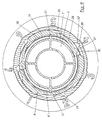
- FIG. 9 again shows a section in the plane IX-IX in FIG Fig. 8. Identical components are given the same reference numbers designated.
- Fig. 9 is visible that the elevations 21 and 21 'to the outer surface 20 of the cylinder portion 7 'of Inner cylinder 7 can strike the driver 19, that of the inner surface 18 of the cylinder portion 8 'of the Outer cylinder 8 protrude.
- the drivers 19 of the fixed inner cylinder 7 hinder one Continue rotation of the outer cylinder 8 on the position of Survey 21 and 21 'addition.
- the outer cylinder 8 can therefore only be rotated by 180 ° and then the further rotation through the survey 21 and 21 'stopped.
- Fig. 10 shows the view of a shell device whose Shell dome for the purpose of clarification of the inner Design of the feed bowl 4 has been omitted. Same components are given the same reference numbers designated.
- Fig. 10 illustrates in particular that the feed bowl. 4 has a feeding dish in the area of his Tellerrandes 40 connecting members 41 and 42 for connection having the shell dome 6 not visible here.
- the connecting members 41 and 42 include a hinged joint 43 and at least one locking or retaining element 44.
- An annular surface of the feeding plate, which is around the under Fall pipe 3 located center plate runs around is subdivided into feeding sections, each feeding section consisting of at least one bag, a field or the like Indentation or demarcation indented 45 consists.
- the number of feeding sections is equal to one Multiples of the number of paddles or wings 10th trained bridge organs 9 of the outer cylinder 8, of here the cylinder sections 8 'and 8' 'are visible, with the gap region 11 between them.
Landscapes
- Life Sciences & Earth Sciences (AREA)
- Environmental Sciences (AREA)
- Birds (AREA)
- Animal Husbandry (AREA)
- Biodiversity & Conservation Biology (AREA)
- Feeding And Watering For Cattle Raising And Animal Husbandry (AREA)
- Fodder In General (AREA)
Description
- Fig. 1
- eine Ansicht der am Futterförderrohr hängenden Schaleneinrichtung einer Vorrichtung für die Fütterung von Broilern,
- Fig. 2
- eine Ansicht eines Außenzylinders,
- Fig. 3
- eine Seitenansicht des Außenzylinders gemäß Fig. 2 in einem Halbschnitt,
- Fig. 4
- eine Ansicht des Innenzylinders, mit oberem Rohradapter zur Befestigung am Futterförderrohr ohne schließendes Oberteil,
- Fig. 5
- eine Seitenansicht des Innenzylinders in einem Halbschnitt,
- Fig. 6
- eine Seitenansicht der Vorrichtung entsprechend Fig. 1 in einem Halbschnitt bei angehobenem Futterförderrohr, so daß die Futterschale über dem Boden eines Stalles frei hängt,
- Fig. 7
- die aus Innenzylinder und darauf geführtem Außenzylinder gebildete Einheit eines Fallrohres im Schnitt entlang der Linie VII - VII in Fig. 6,
- Fig. 8
- eine Seitenansicht der Vorrichtung bei abgesenktem Futterförderrohr, so daß die Futterschale auf dem Boden des Stalls aufgesetzt ist,
- Fig. 9
- einen Schnitt durch das aus Innen zylinder und Außenzylinder gebildete Fallrohr der Vorrichtung gemäß Fig. 8 im Schnitt entlang der Linie IX - IX in Fig. 8, und
- Fig. 10
- eine Ansicht einer Futterschale, bei der zwecks Verdeutlichung ihres Futtertellers die Schalenkuppel weggelassen wurde.
Claims (19)
- Vorrichtung für die Fütterung von in einem Stall freilaufend gehaltenem Geflügel, insbesondere Mastgeflügel, vorzugsweise Broiler, mit mindestens einem über dem Boden des Stalls heb- und senkbar gehaltenen Futterförderrohr (1), das eine Reihe von Abzweigöffnungen hat, von denen jede einer am Förderrohr hängenden Schaleneinrichtung (2) zugeordnet ist, die ein von der Abzweigöffnung abgehendes Fallrohr (3) und eine unter dem Fallrohr befindliche Futterschale mit aus speichenartig verlaufenden Gitterstäben gebildeter Schalenkuppel aufweist, wobei das Fallrohr aus einem von der Abzweigöffnung abgehenden Innenzylinder (7) sowie einem den Innenzylinder umschließenden Außenzylinder (8) besteht, an dem die Schale mittels der Gitterstäbe ihrer Schalenkuppel (6) derart hängt, daß sie bei abgesenktem Futterförderrohr aufsetzt, insbesondere auf dem Boden (34) des Stalls aufsetzt, wobei der Außenzylinder an dem Innenzylinder drehbar sowie heb- und senkbar geführt ist und wenigstens ein den Hebund Senkweg begrenzender Hubanschlag vorgesehen ist,
dadurch gekennzeichnet, daß sie wenigstens einen den Drehweg des Außenzylinders (8) gegenüber dem Innenzylinder (7) begrenzenden Drehanschlag aufweist. - Vorrichtung nach Anspruch 1, dadurch gekennzeichnet, daß jeder Drehanschlag wenigstens eine in einem vorbestimmten Bereich der Außenfläche (20) des Innenzylinders (7) angeordnete Erhebung (21, 21') aufweist sowie mindestens einen an der Innenfläche (18) des Außenzylinders (8) befindlichen Mitnehmer (19), in dessen bei Drehung des Außenzylinders (8) um den Innenzylinder (7) ausgeführten Drehweg die Erhebung (21, 21') vorsteht.
- Vorrichtung nach Anspruch 2, dadurch gekennzeichnet, daß der vorbestimmte Bereich der Außenfläche (20) des Innenzylinders (7) sein oberes Kopfteil ist, das mittels vermindertem Zylinderdurchmesser gegenüber dem übrigen Teil des Innenzylinders (7) abgesetzt ist.
- Vorrichtung nach einem der vorhergehenden Ansprüche, dadurch gekennzeichnet, daß die Außenfläche (20) eines oberen Zylinderabschnitts des Außenzylinders (8) als Gewindespindel (15) ausgebildet ist, und daß die freien Enden der Gitterstäbe (5) der Schalenkuppel (6) an einen Schraubring (17) angeschlossen sind, der auf den als Gewindespindel (15) ausgebildeten Bereich des Außenzylinders (8) geschraubt ist.
- Vorrichtung nach einem der Ansprüche 1 und 4, dadurch gekennzeichnet, daß der Außenzylinder (8) in seinem als Gewindespindel (15) ausgebildeten Bereich wenigstens einen federelastischen Rastnocken (27) aufweist.
- Vorrichtung nach Anspruch 5, dadurch gekennzeichnet, daß jeder Rastnocken (27) als in radialer Richtung federelastischer Rastnocken (27) ausgebildet ist.
- Vorrichtung nach einem der Ansprüche 4 bis 6, dadurch gekennzeichnet, daß der Schraubring (17) der Schalenkuppel (6) an seiner Innenumfangsfläche (36) Ausnehmungen (37) aufweist, mit welchen die Rastnocken (27) formschlüssig verrastbar sind.
- Vorrichtung nach Anspruch 7, dadurch gekennzeichnet, daß die Rastnocken (27) und die Ausnehmungen (37) schräg zur Drehbewegung ausgerichtete Auflaufflanken (38, 39) aufweisen.
- Vorrichtung nach einem der Ansprüche 1 bis 8, dadurch gekennzeichnet, daß der Außenzylinder (8) und der Innenzylinder (7) jeweils aus einander benachbarten, zueinander koaxialen Zylinderabschnitten (8', 8'', 7', 7") bestehen, wobei einander zugekehrte Stirnrandbereiche der Zylinderabschnitte (8', 8'', 7', 7'') miteinander verbunden sind über Brückenorgane (9), die einen Spaltbereich (11, 22) überbrücken, der dem Abstand zwischen den Zylinderabschnitten (8', 8'', 7', 7'') entspricht.
- Vorrichtung nach Anspruch 9, dadurch gekennzeichnet, daß der Innenzylinder (7) derart ausgebildet ist, daß sein endseitiger Zylinderabschnitt (7'') den Spaltbereich (11, 22) zwischen den Zylinderabschnitten (8', 8'') des Außenzylinders (8) abdeckt, wenn der Außenzylinder (8) mittels einer Anhebung des Futterförderrohres (1) in eine gegenüber dem Innenzylinder (7) abgesenkte Position bewegt ist, in welcher die Hubanschläge (14) von Innenzylinder (7) und Außenzylinder (8) in gegenseitiger Anlage stehen.
- Vorrichtung nach einem der Ansprüche 9 und 10, dadurch gekennzeichnet, daß der Hubanschlag (14) aus einem Rezeß (13) der Zylinderinnenfläche (12) des Außenzylinders (8) und wenigstens einer radial vom Innenzylinder (7) vorstehende Auflageschulter (24) für den Rezeß (13) besteht.
- Vorrichtung nach Anspruch 11, dadurch gekennzeichnet, daß jede Auflageschulter (24) für den Rezeß (13) Teil eines kragenflanschähnlichen Radialvorsprunges (25) des Innenzylinders (7) ist.
- Vorrichtung nach einem der Ansprüche 9 bis 12, dadurch gekennzeichnet, daß jedes Brückenorgan (9) ein Flachsteg ist, dessen Stegflächenebene radial zur Achse des jeweiligen Innenzylinders (7) bzw. Außenzylinders (8) ausgerichtet ist.
- Vorrichtung nach Anspruch 13, dadurch gekennzeichnet, daß die als Flachsteg vorliegende Brückenorgane (9) des Außenzylinders (8) die Form von radial über die Peripherie des Außenzylinders (8) in die Futterschale (4) hinein vorstehenden Paddeln bzw. Flügeln (10) aufweisen.
- Vorrichtung nach einem der vorhergehenden Ansprüche, dadurch gekennzeichnet, daß die Futterschale (4) einen Futterteller aufweist, der im Bereich seines Tellerrandes (40) Verbindungsorgane (41, 42) zur Verbindung mit der Schalenkuppel (6) aufweist.
- Vorrichtung nach Anspruch 15, dadurch gekennzeichnet, daß die Verbindungsorgane (41, 42) ein Klappgelenk (43) und wenigstens ein Verriegelungs- bzw. Halteelement (44) aufweisen.
- Vorrichtung nach einem der Ansprüche 15 und 16, dadurch gekennzeichnet, daß eine Ringfläche des Futtertellers, die um das unter dem Fallrohr (3) befindliche Tellerzentrum herum verläuft, in Freßsektionen unterteilt ist.
- Vorrichtung nach Anspruch 17, dadurch gekennzeichnet, daß jede Freßsektion aus wenigstens einer Tasche, einem Feld oder dergleichen durch Vertiefung bzw. Erhebung (21, 21') abgegrenzte Einformung (45) besteht.
- Vorrichtung nach einem der Ansprüche 17 und 18, dadurch gekennzeichnet, daß die Anzahl der Freßsektionen gleich einem vielfachen der Anzahl der als Paddel bzw. Flügel (10) ausgebildeten Brückenorgane (9) des Außenzylinders (8) ist.
Applications Claiming Priority (3)
| Application Number | Priority Date | Filing Date | Title |
|---|---|---|---|
| DE10164122A DE10164122C1 (de) | 2001-12-24 | 2001-12-24 | Vorrichtung für die Fütterung von Geflügel, insbesondere Mastgeflügel, vorzugsweise Broiler |
| DE10164122 | 2001-12-24 | ||
| PCT/DE2002/004475 WO2003055299A1 (de) | 2001-12-24 | 2002-12-06 | Vorrichtung für die fütterung von geflügel, insbesondere mastgeflügel, vorzugsweise broiler |
Publications (3)
| Publication Number | Publication Date |
|---|---|
| EP1458232A1 EP1458232A1 (de) | 2004-09-22 |
| EP1458232B1 true EP1458232B1 (de) | 2005-04-20 |
| EP1458232B2 EP1458232B2 (de) | 2009-01-21 |
Family
ID=7710973
Family Applications (1)
| Application Number | Title | Priority Date | Filing Date |
|---|---|---|---|
| EP02798266A Expired - Lifetime EP1458232B2 (de) | 2001-12-24 | 2002-12-06 | Vorrichtung für die fütterung von geflügel, insbesondere mastgeflügel, vorzugsweise broiler |
Country Status (9)
| Country | Link |
|---|---|
| US (1) | US7552697B2 (de) |
| EP (1) | EP1458232B2 (de) |
| CN (1) | CN1214709C (de) |
| AT (1) | ATE293356T1 (de) |
| BR (1) | BR0207567B1 (de) |
| DE (2) | DE10164122C1 (de) |
| ES (1) | ES2239271T5 (de) |
| RU (1) | RU2282983C2 (de) |
| WO (1) | WO2003055299A1 (de) |
Families Citing this family (54)
| Publication number | Priority date | Publication date | Assignee | Title |
|---|---|---|---|---|
| CA2721236C (en) | 2002-06-26 | 2013-07-30 | Ctb, Inc. | Poultry feeder |
| USD498565S1 (en) | 2003-06-17 | 2004-11-16 | Ctb Ip, Inc. | Rim and spokes of a grill for a feeder |
| USD499218S1 (en) | 2003-06-17 | 2004-11-30 | Ctb Ip, Inc. | Rim of a grill for a feeder |
| USD491320S1 (en) | 2003-06-23 | 2004-06-08 | Ctb Ip, Inc. | Rim for a feed pan |
| USD530045S1 (en) | 2003-06-23 | 2006-10-10 | Ctb Ip, Inc. | Section of a rim for a feeder |
| USD491696S1 (en) | 2003-06-25 | 2004-06-15 | Ctb Ip Inc. | Feed pan |
| BRPI0520395A2 (pt) * | 2005-05-24 | 2009-05-05 | Harish Rajaram Garware | panela de ração singular com grelha automática para a alimentação de pintinhos |
| USD542981S1 (en) | 2005-07-29 | 2007-05-15 | Ctb Ip, Inc. | Poultry feeder |
| US7581512B2 (en) | 2005-10-11 | 2009-09-01 | Ctb, Inc. | Pan breeder feeder |
| US7584716B2 (en) | 2005-10-11 | 2009-09-08 | Ctb, Inc. | Pan breeder feeder |
| US7587990B2 (en) | 2005-10-11 | 2009-09-15 | Ctb, Inc. | Pan breeder feeder |
| USD564712S1 (en) | 2006-10-10 | 2008-03-18 | Ctb Ip, Inc. | Pan of a feeder assembly |
| USD583112S1 (en) | 2006-10-10 | 2008-12-16 | Ctb, Inc. | Grill of a feeder assembly |
| US20080202435A1 (en) * | 2007-02-27 | 2008-08-28 | David Nowacek | Ground based wildlife feeder |
| DE202007003455U1 (de) * | 2007-03-06 | 2007-05-16 | Big Dutchman International Gmbh | Käfiganordnung für Geflügel, vorzugsweise für Masthähnchen (Broiler) |
| WO2008131198A1 (en) * | 2007-04-19 | 2008-10-30 | The Gsi Group, Inc. | Poultry feeder |
| USD625054S1 (en) | 2008-02-08 | 2010-10-05 | David Nowacek | Wildlife feeder |
| NL2001700C2 (en) * | 2008-06-19 | 2009-12-22 | Roxell Nv | Feeding device for poultry having non-sharp-edged circumferentially closed bars or other parts delimiting feed opening between the bars. |
| USD631615S1 (en) * | 2008-10-14 | 2011-01-25 | David Nowacek | Wildlife feeder |
| USD625886S1 (en) * | 2009-01-08 | 2010-10-19 | The Gsi Group, Llc | Animal feeder |
| ES2372139B1 (es) * | 2009-06-25 | 2012-11-23 | Zucami, S.L. | Comedero de aves. |
| US8555812B2 (en) | 2009-09-18 | 2013-10-15 | David Nowacek | Remote monitoring system for ground-based game feeder, varmint guard, tray and skirt assembly and quail feeder |
| MY164301A (en) * | 2009-10-14 | 2017-12-15 | Ptn Ltd | A poultry feeder |
| ES2399737B1 (es) * | 2010-07-02 | 2014-02-25 | Zucami S.L. | Comedero para aves |
| USD683593S1 (en) * | 2011-12-14 | 2013-06-04 | Pipidipi Aps | Serving tray with cooling elements for cans, bottles, or food |
| EA028198B1 (ru) | 2012-10-24 | 2017-10-31 | Биг Дачман Интернэшнл Гмбх | Конвейер и способ транспортировки продуктов жизнедеятельности животных в сельскохозяйственном предприятии |
| CN102972328B (zh) * | 2012-12-04 | 2014-09-03 | 昆明理工大学 | 一种自动喂鱼器 |
| NL2010765C2 (en) * | 2013-05-07 | 2014-11-10 | Roxell Bvba | Poultry feed distribution system with feeding devices having rotatable attachment parts with drop tubes hingedly connected thereto. |
| USD701654S1 (en) * | 2013-06-18 | 2014-03-25 | Francisco Javier Septien Prieto | Bird feeder |
| USD701354S1 (en) * | 2013-06-20 | 2014-03-18 | Francisco Javier Septien Prieto | Bird feeder |
| DE202013104157U1 (de) * | 2013-09-12 | 2013-09-20 | Fienhage Poultry-Solutions Gmbh | Geflügelfutterschale |
| DE202013010980U1 (de) | 2013-12-12 | 2015-03-16 | Big Dutchman International Gmbh | Kontrollfutterschale und Fütterungsanordnung für die Geflügelhaltung |
| US20170258053A1 (en) | 2014-05-15 | 2017-09-14 | The Gsi Group, Llc | Poultry feeder |
| MX365085B (es) * | 2014-07-28 | 2019-04-30 | Javier Septien Prieto Francisco | Comedero para aves. |
| DE202014007282U1 (de) | 2014-09-12 | 2015-12-16 | Big Dutchman International Gmbh | Dosiervorrichtung |
| US9392772B2 (en) * | 2014-10-01 | 2016-07-19 | Valco Companies, Inc. | Poultry feeder storage system |
| US9591833B1 (en) | 2014-10-10 | 2017-03-14 | Southwest Agri-Plastics, Inc. | Storage system for chicken feeders |
| USD786511S1 (en) * | 2015-08-26 | 2017-05-09 | Francisco Javier Septien Prieto | Shutter for a bird feeder |
| CA3010006C (en) * | 2015-12-30 | 2023-06-13 | The Gsi Group Llc | Poultry feeder |
| ITUA20161990A1 (it) * | 2016-03-24 | 2017-09-24 | Giordano Poultry Plast | Mangiatoia per avicoltura |
| DE202016105370U1 (de) | 2016-09-27 | 2018-01-02 | Big Dutchman International Gmbh | Fütterungsvorrichtung für Geflügeltiere |
| PE20200091A1 (es) * | 2017-03-14 | 2020-01-15 | Ctb Inc | Alimentador de bandeja de pollos de engorda |
| CN111093365A (zh) * | 2017-07-27 | 2020-05-01 | 洪淑美 | 家畜饲料均匀喂食系统 |
| WO2019084944A1 (zh) * | 2017-11-06 | 2019-05-09 | 陈响 | 一种新型养猪栏 |
| CN108112397A (zh) * | 2018-02-05 | 2018-06-05 | 上海应用技术大学 | 自带植物灯的培养装置 |
| IT201800006493A1 (it) * | 2018-06-20 | 2019-12-20 | Mangiatoia per l'allevamento di animali con regolazione migliorata del livello di mangime | |
| CN108812362B (zh) * | 2018-07-12 | 2021-11-23 | 乐山傲农康瑞牧业有限公司 | 跑山猪猪舍 |
| CN109937898B (zh) * | 2018-12-29 | 2022-05-10 | 香港民生大数据有限公司 | 喂食设备 |
| USD952265S1 (en) * | 2019-07-11 | 2022-05-17 | Francisco Javier Septien Prieto | Industrial food dispenser model for animals |
| CN112470966B (zh) * | 2020-06-04 | 2022-11-25 | 丰疆智能科技股份有限公司 | 用于养殖场的自动供料系统和自动供料方法 |
| CN112352706B (zh) * | 2020-11-02 | 2021-12-28 | 山东恒基农牧机械有限公司 | 一种养殖用饲料分料装置 |
| RU203190U1 (ru) * | 2020-12-03 | 2021-03-25 | Тимофей Александрович Кондренков | Кормушка для кур |
| CN112841057B (zh) * | 2021-01-08 | 2022-12-30 | 安义县利邦绿色农业有限公司 | 一种养殖喂料装置 |
| CN113875673B (zh) * | 2021-11-19 | 2023-04-07 | 苏州市阳澄湖现代农业发展有限公司 | 一种虾蟹养殖用饲料定量不定点投喂一体机及使用方法 |
Family Cites Families (56)
| Publication number | Priority date | Publication date | Assignee | Title |
|---|---|---|---|---|
| FR1129736A (fr) | 1955-08-08 | 1957-01-24 | Bernard & Cie | Appareil pour la nourriture des volailles |
| US2842096A (en) | 1955-08-23 | 1958-07-08 | Gilbert L Bradfield | Portable selective type hopper and trough feeder |
| US2808029A (en) | 1956-11-30 | 1957-10-01 | Petrus J Geerlings | Hog feeder |
| US2884899A (en) | 1957-04-25 | 1959-05-05 | Jackes Evans Mfg Company | Feeding device for poultry |
| US3102511A (en) | 1961-12-13 | 1963-09-03 | Fmc Corp | Animal feeder |
| DE1181482B (de) | 1963-11-08 | 1964-11-12 | P Lecieux & Cie S A R L Ets | Vorrichtung zur automatischen Beschickung von Futtertellern |
| US3215252A (en) | 1964-02-10 | 1965-11-02 | Deere & Co | Material conveying and distributing device |
| US3388690A (en) * | 1965-10-22 | 1968-06-18 | Chore Time Equipment | Poultry feeder system and pan assembly therefor |
| US3511215A (en) | 1967-12-26 | 1970-05-12 | Chore Time Equipment | Poultry feeder |
| DE1757313C2 (de) * | 1968-04-24 | 1981-10-01 | Chore-Time Equipment, Inc., Milford, Ind. | Fütterungsanlage, insbesondere für Geflügel |
| US3811412A (en) * | 1970-09-22 | 1974-05-21 | Chore Time Equipment | Poultry feeder |
| US3911868A (en) | 1973-07-12 | 1975-10-14 | Chore Time Equipment | Poultry feeder |
| US4070990A (en) | 1976-02-02 | 1978-01-31 | Chore-Time Equipment Inc. | Feeder pan assembly |
| US4216742A (en) | 1978-06-15 | 1980-08-12 | A. R. Wood Manufacturing Company | Multi-tiered cage and feed device |
| FR2483652A1 (fr) | 1980-05-29 | 1981-12-04 | Quemper Martial | Dispositif de reglage de la position axiale d'un manchon sur un support |
| IT8064275U1 (it) | 1980-07-29 | 1982-01-29 | Ska Spa | Mangiatoia con regolazione di livello del mangime, per fuoriuscita inferiore |
| US4348988A (en) * | 1981-01-05 | 1982-09-14 | Cyclone International, Inc. | Poultry feeder with infinite adjustment |
| US4401057A (en) * | 1981-10-05 | 1983-08-30 | Chore-Time Equipment, Inc. | Hog feeder |
| US4476811A (en) * | 1982-09-30 | 1984-10-16 | Chore-Time Equipment, Inc. | Adjustable feeder with brood gate |
| IT1175175B (it) * | 1983-07-13 | 1987-07-01 | Ska Spa | Mangiatoia con regolazione di livello del mangime per volatili d'allevamento, in particolare per tacchini |
| US4527513A (en) * | 1983-11-21 | 1985-07-09 | Ctb, Inc. | Poultry waterer |
| US4676197A (en) * | 1985-10-11 | 1987-06-30 | Ctb, Inc. | Feeder for hogs and like animals |
| ES2010080A6 (es) * | 1989-01-13 | 1989-10-16 | Tigsa | Comedero para aves. |
| US4995343A (en) * | 1989-01-26 | 1991-02-26 | Ctb, Inc. | Feeder apparatus |
| NL8902461A (nl) * | 1989-10-04 | 1991-05-01 | Roxell Nv | Instelbare voederinrichting voor pluimvee. |
| US5097797A (en) * | 1989-10-23 | 1992-03-24 | Intraco, Inc. | Poultry feeder |
| IT1239319B (it) | 1990-04-11 | 1993-10-19 | Ska | Mangiatoia con regolazione di livello del mangime. |
| US5101766A (en) * | 1990-05-30 | 1992-04-07 | Runion Derwood L | Feeder pan |
| US5092274A (en) * | 1990-10-30 | 1992-03-03 | Ctb, Inc. | Poultry feeder |
| US5275131A (en) | 1992-01-14 | 1994-01-04 | North Carolina State University | Male only grill for poultry feeding |
| EP0665711B1 (de) * | 1992-10-05 | 1998-04-08 | Roxell N.V. | Geflügelfütterungseinrichtung |
| US5311839A (en) | 1992-12-15 | 1994-05-17 | Grain Systems, Inc. | Poultry feeder |
| EP0673196B1 (de) | 1992-12-15 | 1997-01-15 | Grain Systems, Inc. | Geflügelfütterer |
| NL9300921A (nl) * | 1993-05-28 | 1994-12-16 | Roxell Nv | Voederinrichting voor gevogelte. |
| US5406907A (en) * | 1993-11-24 | 1995-04-18 | Big Dutchman Inc. | Controlled pan feeder system for poultry |
| EP0988787B8 (de) | 1993-12-17 | 2018-10-31 | Nicolas Le Roy | Geflügelfütteranlage |
| US5435267A (en) | 1993-12-22 | 1995-07-25 | Westland Plastics, Ltd. | Livestock feeder |
| US5778821A (en) * | 1995-01-23 | 1998-07-14 | F&M Horwood Nominees Pty. Ltd. | Restricted flow poultry feeder |
| AUPN069895A0 (en) * | 1995-01-23 | 1995-02-16 | F & M Horwood Nominees Pty Ltd | A male fowl feeder |
| US5603285A (en) | 1995-01-27 | 1997-02-18 | Crystal Spring Colony Farms Ltd. | Adjustable shelf feeder for animals to accommodate growth |
| RU2113784C1 (ru) * | 1996-02-06 | 1998-06-27 | Си Ти Би, Инк. | Кормораздаточное устройство для птиц и животных |
| NL1003490C2 (nl) * | 1996-07-03 | 1998-01-07 | Roxell Nv | Voederinrichting voor gevogelte. |
| NL1004149C2 (nl) | 1996-09-30 | 1998-03-31 | Roxell Nv | Voederinstallatie, en klep bestemd voor gebruik in een dergelijke installatie. |
| US5794562A (en) * | 1997-01-21 | 1998-08-18 | Big Dutchman, Inc. | Poultry breeder pan feeding system and pan feeder assembly therefor |
| US6050220A (en) * | 1997-05-23 | 2000-04-18 | Pax Steel Products, Inc. | Poultry feeder with adjustable feed level control |
| US5967083A (en) | 1997-07-22 | 1999-10-19 | Crystal Spring Colony Farm Ltd. | Adjustable feeder for animals |
| US5875733A (en) * | 1997-07-25 | 1999-03-02 | Chen; Ai-Mei | Feeding device for poultry |
| US5927232A (en) * | 1997-08-22 | 1999-07-27 | Gsi Group, Inc. | Poultry feeder |
| ES2149666B1 (es) | 1997-10-15 | 2001-06-01 | Guardia Gener Romeu | Dosificador para pienso. |
| US6173676B1 (en) * | 1997-11-03 | 2001-01-16 | Ctb, Inc. | Adjustable poultry feeder assembly |
| US5941193A (en) | 1997-11-03 | 1999-08-24 | Ctb, Inc. | Adjustable poultry feeder assembly |
| US5957083A (en) | 1998-01-15 | 1999-09-28 | Almin Enterprise Co., Ltd. | Poultry feeder |
| AU2001234487A1 (en) * | 2000-01-19 | 2001-07-31 | The Gsi Group, Inc. | Poultry feeder |
| EP1257166B1 (de) * | 2000-02-02 | 2003-08-20 | Corti Zootecnici S.R.L. | Futterautomat für die geflügelaufzucht |
| IT1317244B1 (it) * | 2000-04-13 | 2003-05-27 | Falcon S R L | Struttura di mangiatoia automatica per avicoli |
| US6655317B1 (en) * | 2002-10-31 | 2003-12-02 | Val Products, Inc. | Adjustable poultry feeder |
-
2001
- 2001-12-24 DE DE10164122A patent/DE10164122C1/de not_active Expired - Fee Related
-
2002
- 2002-12-06 DE DE50202872T patent/DE50202872D1/de not_active Expired - Lifetime
- 2002-12-06 AT AT02798266T patent/ATE293356T1/de not_active IP Right Cessation
- 2002-12-06 US US10/500,078 patent/US7552697B2/en not_active Expired - Lifetime
- 2002-12-06 WO PCT/DE2002/004475 patent/WO2003055299A1/de not_active Ceased
- 2002-12-06 EP EP02798266A patent/EP1458232B2/de not_active Expired - Lifetime
- 2002-12-06 BR BRPI0207567-9A patent/BR0207567B1/pt active IP Right Grant
- 2002-12-06 CN CN02808737.2A patent/CN1214709C/zh not_active Expired - Lifetime
- 2002-12-06 RU RU2004122697/12A patent/RU2282983C2/ru active
- 2002-12-06 ES ES02798266T patent/ES2239271T5/es not_active Expired - Lifetime
Also Published As
| Publication number | Publication date |
|---|---|
| ES2239271T3 (es) | 2005-09-16 |
| CN1214709C (zh) | 2005-08-17 |
| DE50202872D1 (de) | 2005-05-25 |
| US20050072365A1 (en) | 2005-04-07 |
| US7552697B2 (en) | 2009-06-30 |
| EP1458232B2 (de) | 2009-01-21 |
| ES2239271T5 (es) | 2009-06-05 |
| WO2003055299A1 (de) | 2003-07-10 |
| DE10164122C1 (de) | 2003-05-15 |
| BR0207567B1 (pt) | 2010-12-28 |
| BR0207567A (pt) | 2004-09-14 |
| ATE293356T1 (de) | 2005-05-15 |
| EP1458232A1 (de) | 2004-09-22 |
| CN1503622A (zh) | 2004-06-09 |
| RU2282983C2 (ru) | 2006-09-10 |
| RU2004122697A (ru) | 2005-05-20 |
Similar Documents
| Publication | Publication Date | Title |
|---|---|---|
| EP1458231B1 (de) | Vorrichtung für die fütterung von geflügel, insbesondere mastgeflügel, vorzugsweise broiler | |
| EP1458232B2 (de) | Vorrichtung für die fütterung von geflügel, insbesondere mastgeflügel, vorzugsweise broiler | |
| DE69317897T2 (de) | Geflügelfütterungseinrichtung | |
| DE69002574T2 (de) | Einstellbare Füttervorrichtung für Geflügel. | |
| DE68905626T2 (de) | Gefluegelfuetterungsanlage. | |
| DE69700640T2 (de) | Füttervorrichtung für Geflügel | |
| DE602004000985T2 (de) | Schwenkbare Sitzstange | |
| DE69803987T2 (de) | Verstellbarer futtertrog | |
| DE3707564A1 (de) | Tierfuettervorrichtung, insbesondere fuer schweine | |
| EP1206176A1 (de) | Vorrichtung zur versorgung von tieren mit futter | |
| DE68914732T2 (de) | Futtertrog für Schweine und Ferkel. | |
| DE69806324T2 (de) | Futterdosiervorrichtung | |
| DE60117823T2 (de) | Karussellmelkstand zum melken von tieren | |
| DE3685799T2 (de) | Vorrichtung zum versorgen von kleinvieh mit trinkwasser. | |
| EP2848117B1 (de) | Geflügelfutterschale | |
| DE4242188C2 (de) | Dribbeleinrichtung für Trockenfutter | |
| DE102023127267B3 (de) | Modulare hydroponische pflanzkultur-vorrichtung | |
| EP1728422A1 (de) | Futtertrog für Geflügel | |
| DE60106257T2 (de) | Trinkanlage zum Versorgen von Geflügel mit Trinkflüssigkeit | |
| DE202006008589U1 (de) | Tiertränke und Wasserauffangschale für eine Tiertränke | |
| EP1308089A2 (de) | Tiertränke und Verfahren zur Umrüstung derselben | |
| AT526864B1 (de) | Pflanzensäule und Stapelmodul für eine solche | |
| EP1554930B1 (de) | Futterschale | |
| EP0394198A1 (de) | Dung- und Komposträumeinrichtung | |
| DE202005020177U1 (de) | Steige und Pflanztopf |
Legal Events
| Date | Code | Title | Description |
|---|---|---|---|
| PUAI | Public reference made under article 153(3) epc to a published international application that has entered the european phase |
Free format text: ORIGINAL CODE: 0009012 |
|
| 17P | Request for examination filed |
Effective date: 20040527 |
|
| AK | Designated contracting states |
Kind code of ref document: A1 Designated state(s): AT BE BG CH CY CZ DE DK EE ES FI FR GB GR IE IT LI LU MC NL PT SE SI SK TR |
|
| RIN1 | Information on inventor provided before grant (corrected) |
Inventor name: BUSSE, ROLAND |
|
| GRAP | Despatch of communication of intention to grant a patent |
Free format text: ORIGINAL CODE: EPIDOSNIGR1 |
|
| GRAS | Grant fee paid |
Free format text: ORIGINAL CODE: EPIDOSNIGR3 |
|
| GRAA | (expected) grant |
Free format text: ORIGINAL CODE: 0009210 |
|
| AK | Designated contracting states |
Kind code of ref document: B1 Designated state(s): AT BE BG CH CY CZ DE DK EE ES FI FR GB GR IE IT LI LU MC NL PT SE SI SK TR |
|
| PG25 | Lapsed in a contracting state [announced via postgrant information from national office to epo] |
Ref country code: CZ Free format text: LAPSE BECAUSE OF FAILURE TO SUBMIT A TRANSLATION OF THE DESCRIPTION OR TO PAY THE FEE WITHIN THE PRESCRIBED TIME-LIMIT Effective date: 20050420 Ref country code: IE Free format text: LAPSE BECAUSE OF FAILURE TO SUBMIT A TRANSLATION OF THE DESCRIPTION OR TO PAY THE FEE WITHIN THE PRESCRIBED TIME-LIMIT Effective date: 20050420 Ref country code: SK Free format text: LAPSE BECAUSE OF FAILURE TO SUBMIT A TRANSLATION OF THE DESCRIPTION OR TO PAY THE FEE WITHIN THE PRESCRIBED TIME-LIMIT Effective date: 20050420 Ref country code: SI Free format text: LAPSE BECAUSE OF FAILURE TO SUBMIT A TRANSLATION OF THE DESCRIPTION OR TO PAY THE FEE WITHIN THE PRESCRIBED TIME-LIMIT Effective date: 20050420 Ref country code: FI Free format text: LAPSE BECAUSE OF FAILURE TO SUBMIT A TRANSLATION OF THE DESCRIPTION OR TO PAY THE FEE WITHIN THE PRESCRIBED TIME-LIMIT Effective date: 20050420 Ref country code: GB Free format text: LAPSE BECAUSE OF FAILURE TO SUBMIT A TRANSLATION OF THE DESCRIPTION OR TO PAY THE FEE WITHIN THE PRESCRIBED TIME-LIMIT Effective date: 20050420 Ref country code: TR Free format text: LAPSE BECAUSE OF FAILURE TO SUBMIT A TRANSLATION OF THE DESCRIPTION OR TO PAY THE FEE WITHIN THE PRESCRIBED TIME-LIMIT Effective date: 20050420 Ref country code: EE Free format text: LAPSE BECAUSE OF FAILURE TO SUBMIT A TRANSLATION OF THE DESCRIPTION OR TO PAY THE FEE WITHIN THE PRESCRIBED TIME-LIMIT Effective date: 20050420 |
|
| REG | Reference to a national code |
Ref country code: GB Ref legal event code: FG4D Free format text: NOT ENGLISH |
|
| REG | Reference to a national code |
Ref country code: CH Ref legal event code: EP |
|
| REG | Reference to a national code |
Ref country code: IE Ref legal event code: FG4D Free format text: LANGUAGE OF EP DOCUMENT: GERMAN |
|
| REF | Corresponds to: |
Ref document number: 50202872 Country of ref document: DE Date of ref document: 20050525 Kind code of ref document: P |
|
| PG25 | Lapsed in a contracting state [announced via postgrant information from national office to epo] |
Ref country code: DK Free format text: LAPSE BECAUSE OF FAILURE TO SUBMIT A TRANSLATION OF THE DESCRIPTION OR TO PAY THE FEE WITHIN THE PRESCRIBED TIME-LIMIT Effective date: 20050720 Ref country code: GR Free format text: LAPSE BECAUSE OF FAILURE TO SUBMIT A TRANSLATION OF THE DESCRIPTION OR TO PAY THE FEE WITHIN THE PRESCRIBED TIME-LIMIT Effective date: 20050720 Ref country code: SE Free format text: LAPSE BECAUSE OF FAILURE TO SUBMIT A TRANSLATION OF THE DESCRIPTION OR TO PAY THE FEE WITHIN THE PRESCRIBED TIME-LIMIT Effective date: 20050720 Ref country code: BG Free format text: LAPSE BECAUSE OF FAILURE TO SUBMIT A TRANSLATION OF THE DESCRIPTION OR TO PAY THE FEE WITHIN THE PRESCRIBED TIME-LIMIT Effective date: 20050720 |
|
| REG | Reference to a national code |
Ref country code: ES Ref legal event code: FG2A Ref document number: 2239271 Country of ref document: ES Kind code of ref document: T3 |
|
| PG25 | Lapsed in a contracting state [announced via postgrant information from national office to epo] |
Ref country code: PT Free format text: LAPSE BECAUSE OF FAILURE TO SUBMIT A TRANSLATION OF THE DESCRIPTION OR TO PAY THE FEE WITHIN THE PRESCRIBED TIME-LIMIT Effective date: 20050920 |
|
| GBV | Gb: ep patent (uk) treated as always having been void in accordance with gb section 77(7)/1977 [no translation filed] |
Effective date: 20050420 |
|
| REG | Reference to a national code |
Ref country code: IE Ref legal event code: FD4D |
|
| PG25 | Lapsed in a contracting state [announced via postgrant information from national office to epo] |
Ref country code: CY Free format text: LAPSE BECAUSE OF FAILURE TO SUBMIT A TRANSLATION OF THE DESCRIPTION OR TO PAY THE FEE WITHIN THE PRESCRIBED TIME-LIMIT Effective date: 20051206 Ref country code: AT Free format text: LAPSE BECAUSE OF NON-PAYMENT OF DUE FEES Effective date: 20051206 |
|
| PG25 | Lapsed in a contracting state [announced via postgrant information from national office to epo] |
Ref country code: LU Free format text: LAPSE BECAUSE OF NON-PAYMENT OF DUE FEES Effective date: 20051231 Ref country code: MC Free format text: LAPSE BECAUSE OF NON-PAYMENT OF DUE FEES Effective date: 20051231 |
|
| PLBI | Opposition filed |
Free format text: ORIGINAL CODE: 0009260 |
|
| PLAX | Notice of opposition and request to file observation + time limit sent |
Free format text: ORIGINAL CODE: EPIDOSNOBS2 |
|
| 26 | Opposition filed |
Opponent name: VAL PRODUCTS INC. Effective date: 20060120 |
|
| NLR1 | Nl: opposition has been filed with the epo |
Opponent name: VAL PRODUCTS INC. |
|
| EN | Fr: translation not filed | ||
| PLAF | Information modified related to communication of a notice of opposition and request to file observations + time limit |
Free format text: ORIGINAL CODE: EPIDOSCOBS2 |
|
| PLBB | Reply of patent proprietor to notice(s) of opposition received |
Free format text: ORIGINAL CODE: EPIDOSNOBS3 |
|
| PG25 | Lapsed in a contracting state [announced via postgrant information from national office to epo] |
Ref country code: CH Free format text: LAPSE BECAUSE OF NON-PAYMENT OF DUE FEES Effective date: 20061231 Ref country code: LI Free format text: LAPSE BECAUSE OF NON-PAYMENT OF DUE FEES Effective date: 20061231 |
|
| REG | Reference to a national code |
Ref country code: CH Ref legal event code: PL |
|
| PG25 | Lapsed in a contracting state [announced via postgrant information from national office to epo] |
Ref country code: FR Free format text: LAPSE BECAUSE OF NON-PAYMENT OF DUE FEES Effective date: 20051231 |
|
| PG25 | Lapsed in a contracting state [announced via postgrant information from national office to epo] |
Ref country code: FR Free format text: LAPSE BECAUSE OF NON-PAYMENT OF DUE FEES Effective date: 20050420 |
|
| PUAH | Patent maintained in amended form |
Free format text: ORIGINAL CODE: 0009272 |
|
| STAA | Information on the status of an ep patent application or granted ep patent |
Free format text: STATUS: PATENT MAINTAINED AS AMENDED |
|
| 27A | Patent maintained in amended form |
Effective date: 20090121 |
|
| AK | Designated contracting states |
Kind code of ref document: B2 Designated state(s): AT BE BG CH CY CZ DE DK EE ES FI FR GB GR IE IT LI LU MC NL PT SE SI SK TR |
|
| NLR2 | Nl: decision of opposition |
Effective date: 20090121 |
|
| NLR3 | Nl: receipt of modified translations in the netherlands language after an opposition procedure | ||
| NLR3 | Nl: receipt of modified translations in the netherlands language after an opposition procedure | ||
| REG | Reference to a national code |
Ref country code: ES Ref legal event code: DC2A Date of ref document: 20090417 Kind code of ref document: T5 |
|
| PGFP | Annual fee paid to national office [announced via postgrant information from national office to epo] |
Ref country code: IT Payment date: 20191216 Year of fee payment: 18 |
|
| PG25 | Lapsed in a contracting state [announced via postgrant information from national office to epo] |
Ref country code: IT Free format text: LAPSE BECAUSE OF NON-PAYMENT OF DUE FEES Effective date: 20201206 |
|
| PGFP | Annual fee paid to national office [announced via postgrant information from national office to epo] |
Ref country code: DE Payment date: 20211022 Year of fee payment: 20 |
|
| PGFP | Annual fee paid to national office [announced via postgrant information from national office to epo] |
Ref country code: NL Payment date: 20211217 Year of fee payment: 20 Ref country code: BE Payment date: 20211217 Year of fee payment: 20 |
|
| PGFP | Annual fee paid to national office [announced via postgrant information from national office to epo] |
Ref country code: ES Payment date: 20220119 Year of fee payment: 20 |
|
| REG | Reference to a national code |
Ref country code: DE Ref legal event code: R071 Ref document number: 50202872 Country of ref document: DE |
|
| REG | Reference to a national code |
Ref country code: NL Ref legal event code: MK Effective date: 20221205 |
|
| REG | Reference to a national code |
Ref country code: BE Ref legal event code: MK Effective date: 20221206 |
|
| REG | Reference to a national code |
Ref country code: ES Ref legal event code: FD2A Effective date: 20230504 |
|
| PG25 | Lapsed in a contracting state [announced via postgrant information from national office to epo] |
Ref country code: ES Free format text: LAPSE BECAUSE OF EXPIRATION OF PROTECTION Effective date: 20221207 |