EP1458073B1 - Bausatz für Verteilerschränke - Google Patents
Bausatz für Verteilerschränke Download PDFInfo
- Publication number
- EP1458073B1 EP1458073B1 EP04006018A EP04006018A EP1458073B1 EP 1458073 B1 EP1458073 B1 EP 1458073B1 EP 04006018 A EP04006018 A EP 04006018A EP 04006018 A EP04006018 A EP 04006018A EP 1458073 B1 EP1458073 B1 EP 1458073B1
- Authority
- EP
- European Patent Office
- Prior art keywords
- frame
- profile
- kit according
- construction kit
- frame profile
- Prior art date
- Legal status (The legal status is an assumption and is not a legal conclusion. Google has not performed a legal analysis and makes no representation as to the accuracy of the status listed.)
- Expired - Lifetime
Links
- 238000009826 distribution Methods 0.000 title claims description 23
- 238000003780 insertion Methods 0.000 claims description 32
- 230000037431 insertion Effects 0.000 claims description 32
- 229910052751 metal Inorganic materials 0.000 claims description 14
- 239000002184 metal Substances 0.000 claims description 14
- 125000006850 spacer group Chemical group 0.000 claims description 12
- 238000007789 sealing Methods 0.000 claims description 9
- 239000007787 solid Substances 0.000 claims description 7
- 238000000034 method Methods 0.000 claims description 5
- 239000011248 coating agent Substances 0.000 claims description 3
- 238000000576 coating method Methods 0.000 claims description 3
- 239000000428 dust Substances 0.000 claims description 3
- 238000004519 manufacturing process Methods 0.000 claims description 2
- 230000005855 radiation Effects 0.000 claims description 2
- 238000010276 construction Methods 0.000 claims 20
- 239000004744 fabric Substances 0.000 description 5
- 241000511343 Chondrostoma nasus Species 0.000 description 3
- 241001295925 Gegenes Species 0.000 description 3
- 229910052782 aluminium Inorganic materials 0.000 description 3
- XAGFODPZIPBFFR-UHFFFAOYSA-N aluminium Chemical compound [Al] XAGFODPZIPBFFR-UHFFFAOYSA-N 0.000 description 3
- 239000000243 solution Substances 0.000 description 3
- 239000000725 suspension Substances 0.000 description 3
- 238000006073 displacement reaction Methods 0.000 description 2
- 238000005553 drilling Methods 0.000 description 2
- 230000005670 electromagnetic radiation Effects 0.000 description 2
- 238000009434 installation Methods 0.000 description 2
- 229920000642 polymer Polymers 0.000 description 2
- 238000010079 rubber tapping Methods 0.000 description 2
- XLYOFNOQVPJJNP-UHFFFAOYSA-N water Substances O XLYOFNOQVPJJNP-UHFFFAOYSA-N 0.000 description 2
- 241001136792 Alle Species 0.000 description 1
- 241001494479 Pecora Species 0.000 description 1
- 239000004411 aluminium Substances 0.000 description 1
- 238000005452 bending Methods 0.000 description 1
- 239000000969 carrier Substances 0.000 description 1
- 238000005520 cutting process Methods 0.000 description 1
- 230000001419 dependent effect Effects 0.000 description 1
- 230000000694 effects Effects 0.000 description 1
- 238000002347 injection Methods 0.000 description 1
- 239000007924 injection Substances 0.000 description 1
- 238000001746 injection moulding Methods 0.000 description 1
- 238000000465 moulding Methods 0.000 description 1
- 239000012811 non-conductive material Substances 0.000 description 1
- 230000003287 optical effect Effects 0.000 description 1
- 230000002093 peripheral effect Effects 0.000 description 1
- 210000002023 somite Anatomy 0.000 description 1
- 239000007921 spray Substances 0.000 description 1
- 238000003892 spreading Methods 0.000 description 1
- 238000003860 storage Methods 0.000 description 1
- 238000009423 ventilation Methods 0.000 description 1
Images


Classifications
-
- H—ELECTRICITY
- H02—GENERATION; CONVERSION OR DISTRIBUTION OF ELECTRIC POWER
- H02B—BOARDS, SUBSTATIONS OR SWITCHING ARRANGEMENTS FOR THE SUPPLY OR DISTRIBUTION OF ELECTRIC POWER
- H02B1/00—Frameworks, boards, panels, desks, casings; Details of substations or switching arrangements
- H02B1/26—Casings; Parts thereof or accessories therefor
- H02B1/50—Pedestal- or pad-mounted casings; Parts thereof or accessories therefor
-
- H—ELECTRICITY
- H02—GENERATION; CONVERSION OR DISTRIBUTION OF ELECTRIC POWER
- H02B—BOARDS, SUBSTATIONS OR SWITCHING ARRANGEMENTS FOR THE SUPPLY OR DISTRIBUTION OF ELECTRIC POWER
- H02B1/00—Frameworks, boards, panels, desks, casings; Details of substations or switching arrangements
- H02B1/01—Frameworks
- H02B1/014—Corner connections for frameworks
Definitions
- the invention relates to a distribution cabinet, which is usually placed outdoors and the technical, z. B. electrical or optical distribution systems for z. B. low power systems, such as telephone systems, with associated power supply facilities and Jardinab - / - connecting devices for a specific spatial area receives.
- Such distribution cabinets must - in addition to a sufficient structural stability and sufficient IP security, so tightness against rain and water spray, and a resistance to vandalism, etc. - meet today further demands, for example, may not be delivered to strong electromagnetic radiation to the environment, and For use, especially in warmer countries, the temperatures inside the distribution cabinet must not rise too high, despite the housed there, heat-emitting electrical components, but not too low.
- Such distribution cabinets are basically made of either metal or plastic, wherein plastic combines the advantage of cheaper manufacturability with the advantage of an electrically non-conductive material, so that even with unscheduled contacts of the housing of the distribution cabinet by an electrical component never the risk that at Touching the case from the outside the person concerned receives an electric shock.
- Document EP 1 047 167 A1 discloses a distribution cabinet and a kit for producing such a distribution cabinet, wherein the distribution cabinet is at least partially made of plastic.
- the distribution cabinet which is intended for receiving low power distribution systems, comprises a base box, a cabinet body with at least one door, a cabinet lid and a mounted inside mounting frame.
- the frame comprises two rectangular sub-frames, each connected at the four corners by means of horizontally extending beams to provide a frame with a rectangular parallelepiped profile.
- the sub-frames each comprise two upright, parallel columns and two parallel transverse elements.
- the supports and cross members are connected in the corners in each case via connecting parts.
- the connecting parts have two pins extending at right angles to one another, which are respectively inserted into the transverse element and the upright support in their ends.
- the carriers are also screwed to the connecting elements, wherein profiled projections of the connecting elements engage in the profile of the carrier.
- a carcass frame of an interior carcass can be created by the first frame profile is cut in the desired items to length with the Würfelverbindem, preferably frame profiles along some and especially all outer edges of the mostly cubic carcass frame are arranged.
- frame-shaped side parts are possible, which are connected only by one or two transverse struts, for example in the lower region, to a then open in the upper part of the carcass frame.
- the kit also includes at least one attachment part for an outer lining of the body frame with shielding plates (for the purpose of electromagnetic shielding of the inner body), in particular in the form of insertable into the outer surfaces of the frame profiles, removable and / or disposable Einsteckprofiles or in the form of holding plugs
- shielding plates for the purpose of electromagnetic shielding of the inner body
- the exterior planking of the body frame and thus the completion of the interior carcass are completed very easily and quickly.
- a second combined (against moisture / dust on the one hand and EMC radiation on the other hand) seal is placed between the frame profiles and the shield plates, in particular by impressing appropriately deflected pieces of the combined seal into corresponding grooves of the frame profiles.
- the kit in addition to a first frame profile, also includes a second, with respect to its cross-section smaller, frame profile, the structure of which is otherwise analogous to the first frame profile, and further suitable for this second frame profile second cube connectors and possibly also second angle connectors, which are described below.
- the second frame profile is used to create smaller and therefore less stable body frame needed.
- the kit also includes a third frame profile whose cross-sectional size corresponds to that of the second frame profile, but which has a plate-shaped extension parallel to and in alignment with one of the outer surfaces of the cross section of the profile in one piece.
- This third profile shape is preferably used to create not completely self-contained, smaller, profile frame, wherein the plate-shaped extension for attaching, in particular screwing, is used by equipment parts of the distribution cabinet.
- the kit for attaching other profiles, in particular in the form of transverse struts, but also other components such as mounting frame, electrical fittings, etc., the kit further comprises an angle connector whose two legs are arranged at right angles to one leg against the outer surface of one of the profiles and whose other leg bends away from it at right angles. Both legs are equipped with through holes. Compared to the profile, the fixation is done by inserting a screw and screwing in a groove nut inside an undercut groove of the profile.
- the widened head is formed in the plan oblong, so that they can be aligned in alignment with the undercut groove of the open side, ie not frontally, introduced and then secured by rotation there form-fitting.
- two or more suspension hooks can be attached to the profiles on the top of the inner carcass to lift the entire inner carcass, possibly already provided with Abstandsbeplankung, using a crane and move.
- the kit preferably comprises a sliding door attachment part for attaching and supporting a sliding door on the inner carcass, rotating lugs for positively fixing a shield plate as a bottom plate on the inner carcass, securing sleeves for fixing in an undercut groove of one of the profiles and for attaching a securing bracket against folding the door, and a first combined gasket for sealing the doors from the rest of the interior body when the door is closed.
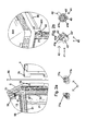
- Figures 7 to 12 show the increasingly completed building phases of a body 3, wherein with the aid of the kit according to the invention different sized carcasses are produced, namely from different profiles 51 - 53 as shown in FIG. 1d - 1f and the associated attachments.
- the inner body has a cubic shape and is intrinsically stable due to a carcass frame 16, composed of edge profiles 17, which are connected at their ends, in particular in the corners of the body frame 16, via corresponding corner connectors together, in particular screwed.
- transverse struts 34 horizontally circumferentially between the vertical struts in the lower third of the body frame 16, against which Justier screws 13 are also arranged horizontally directed from outside to inside.
- the adjusting screws 13 are arranged in pairs spaced from each other in each case in the transverse direction extending front and rear cross member 34, preferably also one in the middle of the transversely to the transverse direction 20 extending short crossbars.
- the body frame 16 is closed at the sides, at the back and at the top by - preferably EMC-density plates, which are preferably in the thickness range of the edge profiles 17, so that only the front, in particular only the area lying above the transverse strut 34, is open as well as the base area between the bottom circumferential edge profiles 17th
- FIG. 8 shows a state in which the inner body 21 thus described is already provided with side walls 8, which are set from the outside against the side surfaces of the inner body 21 and are positively connected thereto by lowering or fixed in another manner.
- Fig. 9 shows a state in which compared to the equipment of FIG. 8, a front flap 23 and a tailgate 24 - preferably as the side walls 8 and the rest of the panel preferably made of plastic - the front and rear lower area cover the inner body 21 in that they are also preferably positively attached to these from the outside or otherwise secured and thereby close the area of the trailing in the lower third cross braces to the lower end of the body frame 16 front and rear, while yes the side walls 8 over the entire height of the body frame 21 preferably go through.
- FIG. 10 shows a state in which the inner body 21 is additionally provided with a rear wall 11 and front doors 4a, b.
- the doors 4a, b are mounted on the longitudinal outer edges of the front in corresponding hinges as a pivot axis, while the rear wall 11 is in turn secured from the outside by hanging from above or otherwise.
- the rear wall 11, side walls 8 are offset outward toward the inner body 21 at a distance - open at the top and bottom - so that air can flow upwards through the chimney effect in between.
- the doors 4a, b are double-walled for the same reason formed with through holes from bottom to top, wherein preferably the inner wall of the doors 4a, b again EMV-tight.
- roof module 50 which consists of an upper intermediate part 7 and a cover 5, and preferably downwardly projecting extensions 25 for insertion into the remaining body 3, in particular between the inner body 21st and its outer panel and screw with the inner body 21, in particular its body frame 16 serve.
- the roof module 50 protrudes beyond the inner body 21 and also covers the rear wall 11, side walls 8 and the doors 4a, b in the closed state, prevents the fixed roof module 50 - as shown in the final state of FIG. 12 - lifting these parts upwards and thus their distance from the inner body 21st
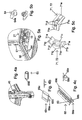
- FIGS. 1 to 6 show individual installation situations or the individual parts installed therein.
- FIG. 1a to 1c show a corner of a profile frame, created from two deflected to the desired extent pieces of a first frame profile 51, which abut with their end faces on two adjacent, at right angles to each other, outer surfaces of a matching first cube connector 61 and with screwed to this.
- In the center of the cross section is a circumferentially closed central bore 54.
- In the outer corners are each identical diagonal grooves 55 which are diagonally open to the outside and have a slight undercut.
- generously undercut T-slots 56 are arranged in the center, the opening width 70 of which is at most half of the greatest width of the undercut part and not more than one third of the width of the profile 51.
- an inner body can also be made from the second frame profile 52, which is smaller in cross-section but otherwise analogous, with matching attachments, in particular cube connectors 62 and angle connectors 72.
- Fig. 1f shows a third frame profile 53, which has a plate-shaped extension 57, formed integrally with the frame profile 53 and aligned with one of its outer surfaces.
- the remainder of the third frame profile 53 corresponds to the outer frame dimensions of the second frame profile 52, but only in an outer corner a diagonal groove 55 'is formed, diagonally opposite the corner from which the plate-shaped extension 57 carries.
- the remaining corner areas are formed with a closed outer corner and arranged in the corner area enclosed, round recess.
- This third frame profile is used primarily for creating profile frame parts, such as side frames, wherein the plate-shaped extension 57 are preferably arranged facing inside such a rectangular frame part, and above all this third frame profile 53 can also be combined with the second frame profile 52 ,
- the diagonal grooves 55 and 55 are not only the same design, but also the same size for both profile sizes, ie all three frame profiles 51 to 53, so that the same seals to be accommodated there can be inserted.
- the first cube connector 61 is screwed to the end faces of the adjacent frame profiles 51 by having through holes in the direction 50 of the two frame profiles and also in the third direction through which a fastening screw can be screwed into the central bore 54 of the adjacent frame profile 51, namely in an in the central bore 54 self-tapping previously screwed first dowel sleeve 58, which has an internal thread additionally a metric thread for receiving the mounting screw.
- a corner connector 71 is screwed, which serves in practice primarily the blunt attachment of a frame profile 51, for example, as a cross member 34, as shown in FIGS. 7 to 12, to a side surface of another, continuous frame profile ,
- a corner connector 71 and 72 as shown as a single part in Fig. 5c, two at right angles to each other extending legs 71a, b, which are mutually stiffened by triangular, so integrally connected web walls 71c.
- the legs 71a, b is in each case a through hole 71d, which extends in the direction of the bisector between the legs 71a, b to facilitate molding of this part produced by injection molding.
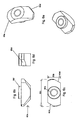
- the corresponding groove nut 60 or 80 matching the first frame profile 51 and second or third frame profile 52 is shown as a single part in Figs. 6: It consists of a widened head portion 60a and a contrast narrower, preferably circular shaft portion 60f whose outer diameter is smaller than the opening width 70 of the corresponding T-groove 56th
- the widened head portion 60a is elongated in plan view, with a width 60b less than the opening width 70 of the T-groove 56, so that the groove nut 60 and 80 with appropriate alignment not only from the front side, but also from the open longitudinal side can be introduced into the T-slot.
- the nut 60 whose head portion 60a rotates about a maximum of about 50 ° in the T-groove 56, and then lies with the purpose for this purpose at the diagonally opposite two corners formed bevels 60d on the side edges of the T-groove.
- Through the shaft portion 60f and preferably through the entire groove nut extends through a threaded hole 60e, in which a corresponding, not shown fastening screw can be screwed.
- the chamfers 60d are formed at the two diagonally opposite corners, which engage when screwing a screw into the threaded hole 60e against the longitudinal edges of the T-slot.
- suspension hooks 67 can be attached to the top of the profile frame 16 to hang the entire body, or at least the inner body 21 with or without partial Abstandsbeplankung to a crane or the like and to transport to the desired location ,
- outer holder 40 which are shown except in the exemplary illustration of Fig. 1 still in Figs. 4a and especially Figs. 2a, 2b are secured by means of these lock nuts 60 and 80 to the profiles 51 to 53.
- Larger carcasses may, for example, have a plurality of rear walls next to each other, and / or sliding doors 14.
- outer holder 40 can be used for attachment of the outer body, as shown in the lower part of Fig. 2b as individual parts in different perspective views.
- the main body 41 of the outer holder 42 is cup-shaped with a bottom 41 a and four circumferential walls 41 b designed, wherein from one of the side walls and thus parallel to the bottom 41a radially outwardly a pin 42 which tapers slightly conically towards its free end and a preferably circular cross-section, strives.
- the bottom 41a has on its outer side an elevation 41c, which is square with an edge length slightly smaller than the opening width 70 of the T-groove 56, to which the outer holder 40 is to fit. Accordingly, the outer width of the main body 41 of the outer holder 40 is also less than the width of the associated profile 51st
- the bottom has in the middle, and thus also in the middle of the elevation 41c, a passage opening 43, and also the two adjacent to the pin 42 lying walls 41b two mutually aligned through holes 43 '.
- the pin 42 opposite wall 41b has a further passage opening 43 ", which is suitable for receiving the pin 42 of another outer holder 40.
- a further outer holder 40 can be attached in an analogous manner to a correspondingly higher position on the inside, z. B. a side wall 8 or a rear wall 11 are screwed, there existing fastening thread.
- the higher-lying outer holder 40 preferably four, namely in each case in a corner region of the side wall 8, are then inserted from above onto the pins of the lower, screwed to the inner body 21 outer holder 40 and thereby the outer wall 8 positively secured to the inner body 21, as so is explained with reference to FIGS. 7 to 12.
- FIG. 2b shows a further purpose of the outer holders 40, above all the two outer holders 40 which are arranged on the sides of the inner body in the upper area and are aligned horizontally with each other, of which FIG. 2b shows only the front one.
- FIG. 2b already shows the roof module 500 placed on the inner body from which securing extensions 501 project downwards in such a position that they are outside the inner body 21, but still within the outer body (not shown in FIG. 2b for reasons of clarity) 22, so for example, the side wall 8, projecting down into the height range of the upper outer holder 40, but not colliding with these.
- these securing extensions 501 have a through-hole in alignment with the through-holes of the outer holders 40.
- the roof module 500 can therefore be positively secured to the inner body 21 by horizontally inserted from both sides of the inner body 21 a securing rod 86 in the space between the inner body 21 and outer body 22 from the front while you fürgangsö Maschinenen the securing extensions 501 as well as the through holes of the aligned, bolted to the inner body 21, outer holder 40 penetrates. This happens when the front doors are open or removed.
- the length of the securing rod 86 is dimensioned such that when the doors are closed, the securing rod 86 reliably extends through the passage openings at the rear.
- a folding pull element for example a ring, is attached to the front end of the securing rod 86.
- Fig. 2a the safety bar is not pushed through the local lower, screwed to the inner body 21, outer holder 40, since not yet the roof module 500 is placed in Fig. 2a.
- Fig. 2a shows in the upper part of the body frame 16 from above patch shield plate 13, which consists of a thin aluminum plate, and the body frame 16 and thus the entire body against electromagnetic radiation to seal to the outside.
- the shield plate 13 - which is arranged in an analogous manner on the back and sides - cut to such a size that it rests on the peripheral frame profiles 51, but not the opening width 70 of their arranged in the support surface T-slots 56 covered.
- the holding plug 77 have a plug 77c, which - similar to the head part of the cap nut - is elongated and used for insertion into the T-slot 56 through the opening width 70 and subsequent rotation and thereby jamming.
- the length of the insertion part 77c is slightly larger than the width of the undercut part of the T-groove 56, so that the usually made of plastic part 77 jammed in rotation by 90 ° therein.
- a shaft projects outward through the opening 70 of the T-groove 56 and connects the insertion part 77c to the head part 77a, which also has a spacer 77b corresponding to the thickness of the shield plate 13, but projects radially therefrom.
- the projecting edge of the head part 77a thus rests on the edge region of the shielding plate 13 and securely - after insertion and twisting of the retaining stopper 77 by 90 ° in the T-slot 56 - securely on the profile 51.
- point-only fasteners can also be a linear attachment of the edges of the shield plates 13 carried out, with the help of Einsteckprofilen 68, 69 which are engaged in the direction 50 of the profiles in the opening width 70 whose central grooves 56, and also at least one, preferably on both sides protruding edges 68c, which fix the edge regions of the shield plates 13.
- the U-shaped insertion part 68a has outwardly projecting tabs 68b for hooking in the undercut of the T-groove 56th
- the outer width of the male part 68a is so small that the male profile 68 can be pulled upwardly out of the opening 70 of the T-groove 56 or 56 'without the profile 68 bending appreciably and thus being reused ,
- a reliable mounting in the T-slot 56 is achieved by screwing from the outside into the open side of the U-shaped insertion parts 68a of an expansion screw 63, preferably in the form of a simple sheet-metal screw, after the insertion profile 68 has been inserted into the T-slot 56. Groove 56 was inserted and positioned. As a result, the legs of the U-shaped insertion part 68a are diverged and this hooks form-fitting manner in the T-groove 56th
- edge 68c of this male profile 68 has a spacer 68d in the form of a crank of the edge region.
- this spacer 68d must compensate for something more than the thickness of the shielding plate 13:
- the inner body 21 of the body 3 is a sufficient IP-tightness (against dust, dirt and splash water) and in addition sufficient electromagnetic tightness necessary. This is achieved by using combined IP and EMC gaskets to seal the interior parts of the carcass 21.
- the simple placement of the edge regions of the shielding plates 13 on the profiles 51 and 52 or 53 is not sufficient for sealing.
- a second combined seal 74 inserted into the diagonal groove 55 of the profile 51, and if possible as close as possible circumferentially around the entire circumference of the corresponding shield plate 13.
- the seal 74 protrudes slightly from the diagonal groove 55th outwardly and over the outer periphery of the profile 51 before, and is elastically deformed when placing the edge region of the shield plate 13, since it consists of a mostly solid rubber or soft plastic profile, as is customary for conventional seals.
- the EMC tightness is achieved in that the outer periphery of the seal 74 is coated with a metal mesh, preferably all the protruding from the diagonal groove 55 part, so that the metal fabric also on the plug 74b of the seal of the electrically conductive contact with the has metal profile 51 and of course with the superimposed metal plate of the shield plate 13th
- the first combined seal 73 likewise shown in FIG. 1a is likewise sealed over parts of its outer circumference with such a metal fabric as an EMC seal. It serves for the IP and EMC sealing create the doors, and therefore must have a higher deformability, which is why their plug 73b similar, namely for insertion in Diagonalnut 55, is formed, the sealing part 73a, however, is larger and, above all, a closed hollow profile has, which allows larger deformations.
- the coating with metal fabric must extend over such a large part of the cross section of the seal 73, that the tissue on the one hand contact with the profile 51, preferably in the region of the diagonal groove 55, has and on the other hand reliable device with the closed door in contact when it rests against the seal 73.
- Figure 4a also shows a securing sleeve 65, the end face in the T-slot 56 can be inserted, from the opening width 70, however, is not removable and can be clamped there in a desired position via a transverse bore 65a by means of grub screw.
- the securing sleeve 65 is used for inserting a (not shown) securing bracket, which is usually a U-shaped bent wire clip, with its one free end from above into the securing sleeve 65 and with its other end into a corresponding receiving opening of the inside Door can be plugged to prevent the open door against a slamming by wind or the like.
- FIG. 5b shows rotating lugs 64, which have a radially projecting lug 64a, and a through-bore, through which they can be screwed to a component, for example to a shroud 13, wherein despite being screwed, the lug 64a of the rotating lug 64 is still rotated can be.
- rotating lugs 64 are used - as shown in FIG. 5a - to cover the bottom region of the inner body 21 on the outside by means of a shielding plate 13.
- a shielding plate 13 For this purpose - against the outer edges of the shielding plate 13 set back - rotating lugs 64 screwed to the top of the shield plate 13 and initially the lugs 64 a so placed so that they do not protrude in the direction of the outer edge of the shield plate 13.
- the shield plate 13 can be used with the rotating lugs 64 from below against the underside of the corresponding profile 51 of the inner body 21 and secured after contacting by now the lugs 64a are rotated in the position radially outward with respect to the shield plate 13.
- the lugs 64 a are located at a corresponding height relative to the base surface of the rotating lugs 64, they engage in the T-slot 56 of the profile 51, and lie on the lower edge thereof, whereby the shroud 13 - usually on one of the combined seals 74 induced indirect contact with the profiles 51 are maintained.
- the securing foot 27 of the securing member 83 is further introduced, which is fixed in a form-fitting undercut and projects through the opening width 70 to the outside.
- the thickened foot part of the securing foot 27 thereby fills the T-slot 56 at least in depth, so that the securing foot 27 projects out of the T-slot 56 by a defined amount to the outside.
- On this front end face extending in the longitudinal direction of the profile 51 U-shaped, open at one end securing spring 83a is fixed by screwing, which is characterized in the assembled state at the same distance from the profile 51, as a preferably circumferentially extending notch 28th in the directed against the sliding door 14 end portion of the journal 26th
- the bearing pin 26 is inserted into the locking sleeve 78, ie in the bore 25, so is the locking groove 28 of the bearing pin 26 at the same longitudinal position, such as a spring groove 29 in the outer periphery of the securing sleeve 78.
- the spring groove 29 is so far recessed at one point of the circumference that an open passage to the bore 25 and the underlying securing groove 28 of the bearing pin 26 is made.
- the fork-shaped locking spring 83 a is inserted with their legs on both sides in the spring groove 29 of the locking sleeve 78.
- the one, straight leg of the locking spring 83a abuts the milled part of the spring groove 29 and thereby dives into the correspondingly dimensioned, underlying securing groove 28 of the inner bearing pin 26, whereby this is prevented from axially pulling out of the sleeve 78.
- the other, curved leg of the locking spring 83a engages with its concave curvature the outer circumference at the bottom of the spring groove 29 of the locking sleeve 78, which ensures that when moving the fixing member 81 due to displacement of the sliding door 14 along the profile 51 and the securing member 83 is moved with Thus, the securing spring 83a does not come off the pin part 82a.
Landscapes
- Power Engineering (AREA)
- Engineering & Computer Science (AREA)
- Joining Of Building Structures In Genera (AREA)
- Furniture Connections (AREA)
- Patch Boards (AREA)
- Insulators (AREA)
- Stored Programmes (AREA)
- Assembled Shelves (AREA)
- Housing For Livestock And Birds (AREA)
- Buildings Adapted To Withstand Abnormal External Influences (AREA)
- Cameras Adapted For Combination With Other Photographic Or Optical Apparatuses (AREA)
- Pharmaceuticals Containing Other Organic And Inorganic Compounds (AREA)
- Noodles (AREA)
- Signal Processing For Digital Recording And Reproducing (AREA)
Priority Applications (1)
| Application Number | Priority Date | Filing Date | Title |
|---|---|---|---|
| PL04006018T PL1458073T3 (pl) | 2003-03-12 | 2004-03-12 | Zestaw montażowy dla szafek rozdzielczych |
Applications Claiming Priority (2)
| Application Number | Priority Date | Filing Date | Title |
|---|---|---|---|
| DE10310778 | 2003-03-12 | ||
| DE10310778A DE10310778B4 (de) | 2003-03-12 | 2003-03-12 | Bausatz für Verteilerschränke |
Publications (3)
| Publication Number | Publication Date |
|---|---|
| EP1458073A2 EP1458073A2 (de) | 2004-09-15 |
| EP1458073A3 EP1458073A3 (de) | 2004-09-22 |
| EP1458073B1 true EP1458073B1 (de) | 2007-01-03 |
Family
ID=32748206
Family Applications (1)
| Application Number | Title | Priority Date | Filing Date |
|---|---|---|---|
| EP04006018A Expired - Lifetime EP1458073B1 (de) | 2003-03-12 | 2004-03-12 | Bausatz für Verteilerschränke |
Country Status (7)
| Country | Link |
|---|---|
| EP (1) | EP1458073B1 (pt) |
| AT (1) | ATE350791T1 (pt) |
| DE (2) | DE10310778B4 (pt) |
| DK (1) | DK1458073T3 (pt) |
| ES (1) | ES2277164T3 (pt) |
| PL (1) | PL1458073T3 (pt) |
| PT (1) | PT1458073E (pt) |
Families Citing this family (13)
| Publication number | Priority date | Publication date | Assignee | Title |
|---|---|---|---|---|
| DE102004033976B4 (de) | 2004-07-14 | 2010-09-23 | Berthold Sichert Gmbh | Dachmodul-Bausatz |
| DE102005055880C5 (de) | 2005-11-23 | 2010-10-14 | Berthold Sichert Gmbh | Dachaufsatz für aktive Elemente |
| DE102006055137B3 (de) * | 2006-10-19 | 2008-06-19 | Adc Gmbh | Zweiteiliges Innengehäuse |
| DE102007012079B4 (de) * | 2007-03-13 | 2011-07-14 | ADC GmbH, 14167 | Verteilerschrank mit mehreren Innengehäusen |
| US7659476B2 (en) | 2007-04-30 | 2010-02-09 | Adc Telecommunication, Inc. | Frame arrangement for a telecommunications cabinet |
| USD624171S1 (en) | 2007-10-29 | 2010-09-21 | Adc Gmbh | Roof module |
| DE102008059383B3 (de) * | 2008-11-27 | 2010-06-10 | Adc Gmbh | Vorrichtung zur Aufnahme von Komponenten der Telekommunikations- und Datentechnik |
| DE102011012438B4 (de) * | 2010-11-04 | 2016-04-14 | Berthold Sichert Gmbh | Baukasten für Befestigungsvorrichtung |
| ITVI20120078A1 (it) * | 2012-04-03 | 2013-10-04 | Easy Access Internat Co Limi Ted | Telaio di supporto per macchinario industriale |
| FR3040829B1 (fr) * | 2015-09-04 | 2017-09-01 | Seifel | Armoire |
| RU209947U1 (ru) * | 2021-10-01 | 2022-03-24 | Общество с ограниченной ответственностью «ТСН-электро» | Рамный каркас шкафа для размещения электрооборудования |
| DE102022122979A1 (de) * | 2022-09-09 | 2024-03-14 | Vaillant Gmbh | Dichtes Wärmepumpengehäuse |
| FR3140567B1 (fr) * | 2022-10-06 | 2024-09-27 | Advanced Systems Of Prot | Arceau pour housse de robot |
Family Cites Families (12)
| Publication number | Priority date | Publication date | Assignee | Title |
|---|---|---|---|---|
| DK149875C (da) * | 1975-06-20 | 1987-05-18 | Loegstrup Steel Kvistgaard A S | Tredimensional, sammenskruelig rammekonstruktion |
| DE3030162C2 (de) * | 1980-08-08 | 1984-02-02 | Siemens AG, 1000 Berlin und 8000 München | Gehäuse für elektrotechnische Geräte, insbesondere für die elektrische Nachrichtentechnik |
| DE8127500U1 (de) * | 1981-09-19 | 1982-01-21 | Isert, Hugo, 6419 Eiterfeld | Profilstab von im Umriß rechteckigem Querschnitt |
| DE8130103U1 (de) * | 1981-10-15 | 1982-08-19 | Hartig, Werner, 6054 Rodgau | Profilstab, insbesondere leichtmetallprofilstab, fuer dreidimensionale rahmenstrukturen |
| DE8511217U1 (de) * | 1985-04-16 | 1985-09-05 | ABN Werner Braun GmbH, 7106 Neuenstadt | Verteilerschrank |
| US4997240A (en) * | 1989-03-28 | 1991-03-05 | Siemens Aktiengesellschaft | Modular housing system for electronic equipment |
| DE19654594A1 (de) * | 1996-12-20 | 1998-07-02 | Krone Ag | Freiluftgehäuse zur Aufnahme von Telekommunikationseinrichtungen und Verfharen zur Unterstützung von Freiluftgehäusen |
| DE19711980C2 (de) * | 1997-03-12 | 2001-11-08 | Krone Gmbh | Stationäres Gehäuse mit Wandelementen aus Kunststoff |
| ES2205673T3 (es) * | 1999-04-19 | 2004-05-01 | Berthold Sichert Gmbh | Armario de distribucion. |
| FR2798520B1 (fr) * | 1999-09-15 | 2003-10-17 | Schneider Electric Ind Sa | Chassis equipe d'une ossature metallique a coin de serrage progressif, notamment pour une armoire electrique |
| NO312987B1 (no) * | 2000-05-22 | 2002-07-22 | Norsk Hydro As | En forbindelse mellom konstruksjonsdeler i en rammekonstruksjon samt anordning ved kapsling hvor nevnteforbindelse inngår |
| DE10105993B4 (de) * | 2001-02-09 | 2006-03-09 | Berthold Sichert Gmbh | Bausatz und Verfahren zum Erstellen eines Elektroschrankes für den Außenbereich |
-
2003
- 2003-03-12 DE DE10310778A patent/DE10310778B4/de not_active Expired - Fee Related
-
2004
- 2004-03-12 ES ES04006018T patent/ES2277164T3/es not_active Expired - Lifetime
- 2004-03-12 PT PT04006018T patent/PT1458073E/pt unknown
- 2004-03-12 EP EP04006018A patent/EP1458073B1/de not_active Expired - Lifetime
- 2004-03-12 PL PL04006018T patent/PL1458073T3/pl unknown
- 2004-03-12 DE DE502004002493T patent/DE502004002493D1/de not_active Expired - Lifetime
- 2004-03-12 DK DK04006018T patent/DK1458073T3/da active
- 2004-03-12 AT AT04006018T patent/ATE350791T1/de active
Also Published As
| Publication number | Publication date |
|---|---|
| ES2277164T3 (es) | 2007-07-01 |
| DK1458073T3 (da) | 2007-03-26 |
| PT1458073E (pt) | 2007-02-28 |
| DE10310778B4 (de) | 2010-04-15 |
| EP1458073A3 (de) | 2004-09-22 |
| DE10310778A1 (de) | 2004-09-23 |
| EP1458073A2 (de) | 2004-09-15 |
| DE502004002493D1 (de) | 2007-02-15 |
| PL1458073T3 (pl) | 2007-04-30 |
| ATE350791T1 (de) | 2007-01-15 |
Similar Documents
| Publication | Publication Date | Title |
|---|---|---|
| EP3384567B1 (de) | Rahmengestell für eine schaltschrankanordnung | |
| EP3103168B1 (de) | Rahmenprofil eines rahmengestells für einen schalt- oder verteilerschrank | |
| DE102007012079B4 (de) | Verteilerschrank mit mehreren Innengehäusen | |
| DE69412563T2 (de) | Schrank mit Eckverbindung und ein Schaltschrank mit solchen Verbindungen | |
| EP1064707B1 (de) | Rahmengestell für einen schaltschrank | |
| DE3911900C2 (pt) | ||
| EP1458073B1 (de) | Bausatz für Verteilerschränke | |
| WO2004076278A2 (de) | Überstülpbarer verteilerschrank | |
| EP0332672B1 (de) | Deckenverkleidung | |
| EP0285914A2 (de) | Duschabtrennung | |
| EP1994614B1 (de) | Rahmenkonstruktion für einen schaltschrank, schaltschrank und bausatz für den schaltschrank | |
| DE19813222C1 (de) | Rahmengestell für einen Schaltschrank | |
| DE69936554T2 (de) | Eckpfosten für Schaltschrank und damit ausgerüsteter Schaltschrank | |
| DE202010000660U1 (de) | Bausatz für Metallschränke | |
| AT504198B1 (de) | Rahmenprofil | |
| EP3607624B1 (de) | Anordnung aus einem schaltschranksockel und einem darauf montierten schaltschrankrahmengestell sowie eine entsprechende schaltschrankreihe | |
| DE29509555U1 (de) | Schaltschrank mit Montageplatte als Einzel- oder Anreihschrank | |
| EP0577140B1 (de) | Schaltschrank | |
| DE4107747A1 (de) | Hochfrequenz-geschirmtes gehaeuse | |
| EP1352456B1 (de) | Gehäuse, insbesondere für den einbau elektrischer und elektronischer bauteile | |
| DE4413380C2 (de) | Schaltschrank für elektrische Anlagen | |
| DE19817209A1 (de) | Rahmengestell für einen Schaltschrank | |
| DE10147988B4 (de) | Schaltschrank | |
| DE2901214A1 (de) | Schaltschrank, insbesondere fuer eine elektrische niederspannungsschaltanlage | |
| DE20303064U1 (de) | Überstülpbarer Verteilerschrank |
Legal Events
| Date | Code | Title | Description |
|---|---|---|---|
| PUAI | Public reference made under article 153(3) epc to a published international application that has entered the european phase |
Free format text: ORIGINAL CODE: 0009012 |
|
| PUAL | Search report despatched |
Free format text: ORIGINAL CODE: 0009013 |
|
| AK | Designated contracting states |
Kind code of ref document: A2 Designated state(s): AT BE BG CH CY CZ DE DK EE ES FI FR GB GR HU IE IT LI LU MC NL PL PT RO SE SI SK TR |
|
| AX | Request for extension of the european patent |
Extension state: AL LT LV MK |
|
| AK | Designated contracting states |
Kind code of ref document: A3 Designated state(s): AT BE BG CH CY CZ DE DK EE ES FI FR GB GR HU IE IT LI LU MC NL PL PT RO SE SI SK TR |
|
| AX | Request for extension of the european patent |
Extension state: AL LT LV MK |
|
| RAP1 | Party data changed (applicant data changed or rights of an application transferred) |
Owner name: KRONE GMBH Owner name: BERTHOLD SICHERT GMBH |
|
| 17P | Request for examination filed |
Effective date: 20041001 |
|
| RAP1 | Party data changed (applicant data changed or rights of an application transferred) |
Owner name: KRONE GMBH Owner name: BERTHOLD SICHERT GMBH |
|
| AKX | Designation fees paid |
Designated state(s): AT BE BG CH CY CZ DE DK EE ES FI FR GB GR HU IE IT LI LU MC NL PL PT RO SE SI SK TR |
|
| AXX | Extension fees paid |
Extension state: AL Payment date: 20041002 Extension state: LT Payment date: 20041002 Extension state: MK Payment date: 20041002 Extension state: LV Payment date: 20041002 |
|
| RAP1 | Party data changed (applicant data changed or rights of an application transferred) |
Owner name: BERTHOLD SICHERT GMBH Owner name: ADC GMBH |
|
| GRAP | Despatch of communication of intention to grant a patent |
Free format text: ORIGINAL CODE: EPIDOSNIGR1 |
|
| GRAS | Grant fee paid |
Free format text: ORIGINAL CODE: EPIDOSNIGR3 |
|
| GRAA | (expected) grant |
Free format text: ORIGINAL CODE: 0009210 |
|
| AK | Designated contracting states |
Kind code of ref document: B1 Designated state(s): AT BE BG CH CY CZ DE DK EE ES FI FR GB GR HU IE IT LI LU MC NL PL PT RO SE SI SK TR |
|
| AX | Request for extension of the european patent |
Extension state: AL LT LV MK |
|
| PG25 | Lapsed in a contracting state [announced via postgrant information from national office to epo] |
Ref country code: SI Free format text: LAPSE BECAUSE OF FAILURE TO SUBMIT A TRANSLATION OF THE DESCRIPTION OR TO PAY THE FEE WITHIN THE PRESCRIBED TIME-LIMIT Effective date: 20070103 Ref country code: FI Free format text: LAPSE BECAUSE OF FAILURE TO SUBMIT A TRANSLATION OF THE DESCRIPTION OR TO PAY THE FEE WITHIN THE PRESCRIBED TIME-LIMIT Effective date: 20070103 |
|
| REG | Reference to a national code |
Ref country code: GB Ref legal event code: FG4D Free format text: NOT ENGLISH |
|
| REF | Corresponds to: |
Ref document number: 502004002493 Country of ref document: DE Date of ref document: 20070215 Kind code of ref document: P |
|
| REG | Reference to a national code |
Ref country code: IE Ref legal event code: FG4D Free format text: LANGUAGE OF EP DOCUMENT: GERMAN |
|
| REG | Reference to a national code |
Ref country code: CH Ref legal event code: NV Representative=s name: MICHELI & CIE INGENIEURS-CONSEILS Ref country code: PT Ref legal event code: SC4A Free format text: AVAILABILITY OF NATIONAL TRANSLATION Effective date: 20070213 |
|
| REG | Reference to a national code |
Ref country code: GR Ref legal event code: EP Ref document number: 20070400672 Country of ref document: GR Ref country code: DK Ref legal event code: T3 |
|
| PG25 | Lapsed in a contracting state [announced via postgrant information from national office to epo] |
Ref country code: BG Free format text: LAPSE BECAUSE OF FAILURE TO SUBMIT A TRANSLATION OF THE DESCRIPTION OR TO PAY THE FEE WITHIN THE PRESCRIBED TIME-LIMIT Effective date: 20070404 |
|
| REG | Reference to a national code |
Ref country code: SE Ref legal event code: TRGR |
|
| GBT | Gb: translation of ep patent filed (gb section 77(6)(a)/1977) |
Effective date: 20070404 |
|
| REG | Reference to a national code |
Ref country code: PL Ref legal event code: T3 |
|
| REG | Reference to a national code |
Ref country code: HU Ref legal event code: AG4A Ref document number: E001384 Country of ref document: HU |
|
| ET | Fr: translation filed | ||
| LTIE | Lt: invalidation of european patent or patent extension |
Effective date: 20070103 |
|
| REG | Reference to a national code |
Ref country code: ES Ref legal event code: FG2A Ref document number: 2277164 Country of ref document: ES Kind code of ref document: T3 |
|
| PLBE | No opposition filed within time limit |
Free format text: ORIGINAL CODE: 0009261 |
|
| STAA | Information on the status of an ep patent application or granted ep patent |
Free format text: STATUS: NO OPPOSITION FILED WITHIN TIME LIMIT |
|
| 26N | No opposition filed |
Effective date: 20071005 |
|
| PG25 | Lapsed in a contracting state [announced via postgrant information from national office to epo] |
Ref country code: RO Free format text: LAPSE BECAUSE OF FAILURE TO SUBMIT A TRANSLATION OF THE DESCRIPTION OR TO PAY THE FEE WITHIN THE PRESCRIBED TIME-LIMIT Effective date: 20070103 |
|
| PG25 | Lapsed in a contracting state [announced via postgrant information from national office to epo] |
Ref country code: MC Free format text: LAPSE BECAUSE OF NON-PAYMENT OF DUE FEES Effective date: 20070331 |
|
| PG25 | Lapsed in a contracting state [announced via postgrant information from national office to epo] |
Ref country code: EE Free format text: LAPSE BECAUSE OF FAILURE TO SUBMIT A TRANSLATION OF THE DESCRIPTION OR TO PAY THE FEE WITHIN THE PRESCRIBED TIME-LIMIT Effective date: 20070103 |
|
| PG25 | Lapsed in a contracting state [announced via postgrant information from national office to epo] |
Ref country code: CY Free format text: LAPSE BECAUSE OF FAILURE TO SUBMIT A TRANSLATION OF THE DESCRIPTION OR TO PAY THE FEE WITHIN THE PRESCRIBED TIME-LIMIT Effective date: 20070103 |
|
| PG25 | Lapsed in a contracting state [announced via postgrant information from national office to epo] |
Ref country code: LU Free format text: LAPSE BECAUSE OF NON-PAYMENT OF DUE FEES Effective date: 20070312 |
|
| PG25 | Lapsed in a contracting state [announced via postgrant information from national office to epo] |
Ref country code: TR Free format text: LAPSE BECAUSE OF FAILURE TO SUBMIT A TRANSLATION OF THE DESCRIPTION OR TO PAY THE FEE WITHIN THE PRESCRIBED TIME-LIMIT Effective date: 20070103 |
|
| PGFP | Annual fee paid to national office [announced via postgrant information from national office to epo] |
Ref country code: IE Payment date: 20110322 Year of fee payment: 8 Ref country code: DK Payment date: 20110328 Year of fee payment: 8 |
|
| PGFP | Annual fee paid to national office [announced via postgrant information from national office to epo] |
Ref country code: NL Payment date: 20110328 Year of fee payment: 8 Ref country code: SK Payment date: 20110308 Year of fee payment: 8 Ref country code: SE Payment date: 20110325 Year of fee payment: 8 Ref country code: CZ Payment date: 20110228 Year of fee payment: 8 |
|
| PGFP | Annual fee paid to national office [announced via postgrant information from national office to epo] |
Ref country code: GR Payment date: 20110330 Year of fee payment: 8 |
|
| PGFP | Annual fee paid to national office [announced via postgrant information from national office to epo] |
Ref country code: GB Payment date: 20110324 Year of fee payment: 8 Ref country code: ES Payment date: 20110324 Year of fee payment: 8 |
|
| PGFP | Annual fee paid to national office [announced via postgrant information from national office to epo] |
Ref country code: IT Payment date: 20110329 Year of fee payment: 8 |
|
| PGFP | Annual fee paid to national office [announced via postgrant information from national office to epo] |
Ref country code: HU Payment date: 20120227 Year of fee payment: 9 |
|
| PGFP | Annual fee paid to national office [announced via postgrant information from national office to epo] |
Ref country code: PT Payment date: 20120222 Year of fee payment: 9 |
|
| REG | Reference to a national code |
Ref country code: NL Ref legal event code: V1 Effective date: 20121001 |
|
| REG | Reference to a national code |
Ref country code: SE Ref legal event code: EUG |
|
| PG25 | Lapsed in a contracting state [announced via postgrant information from national office to epo] |
Ref country code: SE Free format text: LAPSE BECAUSE OF NON-PAYMENT OF DUE FEES Effective date: 20120313 |
|
| REG | Reference to a national code |
Ref country code: DK Ref legal event code: EBP |
|
| GBPC | Gb: european patent ceased through non-payment of renewal fee |
Effective date: 20120312 |
|
| REG | Reference to a national code |
Ref country code: GR Ref legal event code: ML Ref document number: 20070400672 Country of ref document: GR Effective date: 20121008 |
|
| REG | Reference to a national code |
Ref country code: DE Ref legal event code: R081 Ref document number: 502004002493 Country of ref document: DE Owner name: TYCO ELECTRONICS SERVICES GMBH, CH Free format text: FORMER OWNER: BERTHOLD SICHERT GMBH, ADC GMBH, , DE Effective date: 20121025 Ref country code: DE Ref legal event code: R081 Ref document number: 502004002493 Country of ref document: DE Owner name: BERTHOLD SICHERT GMBH, DE Free format text: FORMER OWNER: BERTHOLD SICHERT GMBH, ADC GMBH, , DE Effective date: 20121025 Ref country code: DE Ref legal event code: R081 Ref document number: 502004002493 Country of ref document: DE Owner name: BERTHOLD SICHERT GMBH, DE Free format text: FORMER OWNERS: BERTHOLD SICHERT GMBH, 12277 BERLIN, DE; ADC GMBH, 14167 BERLIN, DE Effective date: 20121025 |
|
| REG | Reference to a national code |
Ref country code: IE Ref legal event code: MM4A |
|
| PG25 | Lapsed in a contracting state [announced via postgrant information from national office to epo] |
Ref country code: GB Free format text: LAPSE BECAUSE OF NON-PAYMENT OF DUE FEES Effective date: 20120312 Ref country code: IE Free format text: LAPSE BECAUSE OF NON-PAYMENT OF DUE FEES Effective date: 20120312 |
|
| PG25 | Lapsed in a contracting state [announced via postgrant information from national office to epo] |
Ref country code: GR Free format text: LAPSE BECAUSE OF NON-PAYMENT OF DUE FEES Effective date: 20121008 Ref country code: IT Free format text: LAPSE BECAUSE OF NON-PAYMENT OF DUE FEES Effective date: 20120312 |
|
| PG25 | Lapsed in a contracting state [announced via postgrant information from national office to epo] |
Ref country code: NL Free format text: LAPSE BECAUSE OF NON-PAYMENT OF DUE FEES Effective date: 20121001 |
|
| PG25 | Lapsed in a contracting state [announced via postgrant information from national office to epo] |
Ref country code: DK Free format text: LAPSE BECAUSE OF NON-PAYMENT OF DUE FEES Effective date: 20120331 |
|
| REG | Reference to a national code |
Ref country code: PT Ref legal event code: MM4A Free format text: LAPSE DUE TO NON-PAYMENT OF FEES Effective date: 20130912 |
|
| REG | Reference to a national code |
Ref country code: ES Ref legal event code: FD2A Effective date: 20131030 |
|
| PG25 | Lapsed in a contracting state [announced via postgrant information from national office to epo] |
Ref country code: ES Free format text: LAPSE BECAUSE OF NON-PAYMENT OF DUE FEES Effective date: 20120313 Ref country code: PT Free format text: LAPSE BECAUSE OF NON-PAYMENT OF DUE FEES Effective date: 20130912 Ref country code: CZ Free format text: LAPSE BECAUSE OF NON-PAYMENT OF DUE FEES Effective date: 20130312 |
|
| REG | Reference to a national code |
Ref country code: SK Ref legal event code: MM4A Ref document number: E 1560 Country of ref document: SK Effective date: 20130312 |
|
| PG25 | Lapsed in a contracting state [announced via postgrant information from national office to epo] |
Ref country code: SK Free format text: LAPSE BECAUSE OF NON-PAYMENT OF DUE FEES Effective date: 20130312 |
|
| PG25 | Lapsed in a contracting state [announced via postgrant information from national office to epo] |
Ref country code: HU Free format text: LAPSE BECAUSE OF NON-PAYMENT OF DUE FEES Effective date: 20130313 |
|
| REG | Reference to a national code |
Ref country code: DE Ref legal event code: R082 Ref document number: 502004002493 Country of ref document: DE Representative=s name: HANSMANN & VOGESER, DE |
|
| PGFP | Annual fee paid to national office [announced via postgrant information from national office to epo] |
Ref country code: BE Payment date: 20140328 Year of fee payment: 11 |
|
| REG | Reference to a national code |
Ref country code: DE Ref legal event code: R082 Ref document number: 502004002493 Country of ref document: DE Representative=s name: HANSMANN & VOGESER, DE Effective date: 20140702 Ref country code: DE Ref legal event code: R081 Ref document number: 502004002493 Country of ref document: DE Owner name: BERTHOLD SICHERT GMBH, DE Free format text: FORMER OWNER: BERTHOLD SICHERT GMBH, TYCO ELECTRONICS SERVICES GMBH, , CH Effective date: 20140702 Ref country code: DE Ref legal event code: R082 Ref document number: 502004002493 Country of ref document: DE Representative=s name: WEICKMANN & WEICKMANN, DE Effective date: 20140702 Ref country code: DE Ref legal event code: R082 Ref document number: 502004002493 Country of ref document: DE Representative=s name: PATENTANWAELTE WEICKMANN & WEICKMANN, DE Effective date: 20140702 Ref country code: DE Ref legal event code: R082 Ref document number: 502004002493 Country of ref document: DE Representative=s name: WEICKMANN & WEICKMANN PATENTANWAELTE - RECHTSA, DE Effective date: 20140702 Ref country code: DE Ref legal event code: R081 Ref document number: 502004002493 Country of ref document: DE Owner name: BERTHOLD SICHERT GMBH, DE Free format text: FORMER OWNERS: BERTHOLD SICHERT GMBH, 12277 BERLIN, DE; TYCO ELECTRONICS SERVICES GMBH, SCHAFFHAUSEN, CH Effective date: 20140702 Ref country code: DE Ref legal event code: R082 Ref document number: 502004002493 Country of ref document: DE Representative=s name: WEICKMANN & WEICKMANN PATENT- UND RECHTSANWAEL, DE Effective date: 20140702 |
|
| REG | Reference to a national code |
Ref country code: DE Ref legal event code: R082 Ref document number: 502004002493 Country of ref document: DE Representative=s name: PATENTANWAELTE WEICKMANN & WEICKMANN, DE Ref country code: DE Ref legal event code: R082 Ref document number: 502004002493 Country of ref document: DE Representative=s name: WEICKMANN & WEICKMANN PATENTANWAELTE - RECHTSA, DE Ref country code: DE Ref legal event code: R082 Ref document number: 502004002493 Country of ref document: DE Representative=s name: WEICKMANN & WEICKMANN PATENT- UND RECHTSANWAEL, DE |
|
| REG | Reference to a national code |
Ref country code: FR Ref legal event code: PLFP Year of fee payment: 13 |
|
| REG | Reference to a national code |
Ref country code: FR Ref legal event code: PLFP Year of fee payment: 14 |
|
| PG25 | Lapsed in a contracting state [announced via postgrant information from national office to epo] |
Ref country code: BE Free format text: LAPSE BECAUSE OF NON-PAYMENT OF DUE FEES Effective date: 20150331 |
|
| REG | Reference to a national code |
Ref country code: FR Ref legal event code: PLFP Year of fee payment: 15 |
|
| PGFP | Annual fee paid to national office [announced via postgrant information from national office to epo] |
Ref country code: FR Payment date: 20210322 Year of fee payment: 18 Ref country code: CH Payment date: 20210324 Year of fee payment: 18 |
|
| PGFP | Annual fee paid to national office [announced via postgrant information from national office to epo] |
Ref country code: DE Payment date: 20210329 Year of fee payment: 18 Ref country code: AT Payment date: 20210318 Year of fee payment: 18 Ref country code: PL Payment date: 20210118 Year of fee payment: 18 |
|
| REG | Reference to a national code |
Ref country code: DE Ref legal event code: R119 Ref document number: 502004002493 Country of ref document: DE |
|
| REG | Reference to a national code |
Ref country code: CH Ref legal event code: PL |
|
| REG | Reference to a national code |
Ref country code: AT Ref legal event code: MM01 Ref document number: 350791 Country of ref document: AT Kind code of ref document: T Effective date: 20220312 |
|
| PG25 | Lapsed in a contracting state [announced via postgrant information from national office to epo] |
Ref country code: LI Free format text: LAPSE BECAUSE OF NON-PAYMENT OF DUE FEES Effective date: 20220331 Ref country code: FR Free format text: LAPSE BECAUSE OF NON-PAYMENT OF DUE FEES Effective date: 20220331 Ref country code: DE Free format text: LAPSE BECAUSE OF NON-PAYMENT OF DUE FEES Effective date: 20221001 Ref country code: CH Free format text: LAPSE BECAUSE OF NON-PAYMENT OF DUE FEES Effective date: 20220331 Ref country code: AT Free format text: LAPSE BECAUSE OF NON-PAYMENT OF DUE FEES Effective date: 20220312 |
|
| PG25 | Lapsed in a contracting state [announced via postgrant information from national office to epo] |
Ref country code: PL Free format text: LAPSE BECAUSE OF NON-PAYMENT OF DUE FEES Effective date: 20220312 |