EP1458066B1 - F2-Zweikammerlasersystem mit Linienauswahl - Google Patents
F2-Zweikammerlasersystem mit Linienauswahl Download PDFInfo
- Publication number
- EP1458066B1 EP1458066B1 EP04011567A EP04011567A EP1458066B1 EP 1458066 B1 EP1458066 B1 EP 1458066B1 EP 04011567 A EP04011567 A EP 04011567A EP 04011567 A EP04011567 A EP 04011567A EP 1458066 B1 EP1458066 B1 EP 1458066B1
- Authority
- EP
- European Patent Office
- Prior art keywords
- laser
- gas
- pulse
- discharge
- unit
- Prior art date
- Legal status (The legal status is an assumption and is not a legal conclusion. Google has not performed a legal analysis and makes no representation as to the accuracy of the status listed.)
- Expired - Lifetime
Links
Images



















Classifications
-
- H—ELECTRICITY
- H01—ELECTRIC ELEMENTS
- H01S—DEVICES USING THE PROCESS OF LIGHT AMPLIFICATION BY STIMULATED EMISSION OF RADIATION [LASER] TO AMPLIFY OR GENERATE LIGHT; DEVICES USING STIMULATED EMISSION OF ELECTROMAGNETIC RADIATION IN WAVE RANGES OTHER THAN OPTICAL
- H01S3/00—Lasers, i.e. devices using stimulated emission of electromagnetic radiation in the infrared, visible or ultraviolet wave range
- H01S3/23—Arrangements of two or more lasers not provided for in groups H01S3/02 - H01S3/22, e.g. tandem arrangements of separate active media
- H01S3/2366—Arrangements of two or more lasers not provided for in groups H01S3/02 - H01S3/22, e.g. tandem arrangements of separate active media comprising a gas as the active medium
-
- H—ELECTRICITY
- H01—ELECTRIC ELEMENTS
- H01S—DEVICES USING THE PROCESS OF LIGHT AMPLIFICATION BY STIMULATED EMISSION OF RADIATION [LASER] TO AMPLIFY OR GENERATE LIGHT; DEVICES USING STIMULATED EMISSION OF ELECTROMAGNETIC RADIATION IN WAVE RANGES OTHER THAN OPTICAL
- H01S3/00—Lasers, i.e. devices using stimulated emission of electromagnetic radiation in the infrared, visible or ultraviolet wave range
- H01S3/10—Controlling the intensity, frequency, phase, polarisation or direction of the emitted radiation, e.g. switching, gating, modulating or demodulating
-
- G—PHYSICS
- G01—MEASURING; TESTING
- G01J—MEASUREMENT OF INTENSITY, VELOCITY, SPECTRAL CONTENT, POLARISATION, PHASE OR PULSE CHARACTERISTICS OF INFRARED, VISIBLE OR ULTRAVIOLET LIGHT; COLORIMETRY; RADIATION PYROMETRY
- G01J9/00—Measuring optical phase difference; Determining degree of coherence; Measuring optical wavelength
-
- G—PHYSICS
- G03—PHOTOGRAPHY; CINEMATOGRAPHY; ANALOGOUS TECHNIQUES USING WAVES OTHER THAN OPTICAL WAVES; ELECTROGRAPHY; HOLOGRAPHY
- G03F—PHOTOMECHANICAL PRODUCTION OF TEXTURED OR PATTERNED SURFACES, e.g. FOR PRINTING, FOR PROCESSING OF SEMICONDUCTOR DEVICES; MATERIALS THEREFOR; ORIGINALS THEREFOR; APPARATUS SPECIALLY ADAPTED THEREFOR
- G03F7/00—Photomechanical, e.g. photolithographic, production of textured or patterned surfaces, e.g. printing surfaces; Materials therefor, e.g. comprising photoresists; Apparatus specially adapted therefor
- G03F7/70—Microphotolithographic exposure; Apparatus therefor
- G03F7/70008—Production of exposure light, i.e. light sources
- G03F7/70025—Production of exposure light, i.e. light sources by lasers
-
- G—PHYSICS
- G03—PHOTOGRAPHY; CINEMATOGRAPHY; ANALOGOUS TECHNIQUES USING WAVES OTHER THAN OPTICAL WAVES; ELECTROGRAPHY; HOLOGRAPHY
- G03F—PHOTOMECHANICAL PRODUCTION OF TEXTURED OR PATTERNED SURFACES, e.g. FOR PRINTING, FOR PROCESSING OF SEMICONDUCTOR DEVICES; MATERIALS THEREFOR; ORIGINALS THEREFOR; APPARATUS SPECIALLY ADAPTED THEREFOR
- G03F7/00—Photomechanical, e.g. photolithographic, production of textured or patterned surfaces, e.g. printing surfaces; Materials therefor, e.g. comprising photoresists; Apparatus specially adapted therefor
- G03F7/70—Microphotolithographic exposure; Apparatus therefor
- G03F7/70008—Production of exposure light, i.e. light sources
- G03F7/70041—Production of exposure light, i.e. light sources by pulsed sources, e.g. multiplexing, pulse duration, interval control or intensity control
-
- G—PHYSICS
- G03—PHOTOGRAPHY; CINEMATOGRAPHY; ANALOGOUS TECHNIQUES USING WAVES OTHER THAN OPTICAL WAVES; ELECTROGRAPHY; HOLOGRAPHY
- G03F—PHOTOMECHANICAL PRODUCTION OF TEXTURED OR PATTERNED SURFACES, e.g. FOR PRINTING, FOR PROCESSING OF SEMICONDUCTOR DEVICES; MATERIALS THEREFOR; ORIGINALS THEREFOR; APPARATUS SPECIALLY ADAPTED THEREFOR
- G03F7/00—Photomechanical, e.g. photolithographic, production of textured or patterned surfaces, e.g. printing surfaces; Materials therefor, e.g. comprising photoresists; Apparatus specially adapted therefor
- G03F7/70—Microphotolithographic exposure; Apparatus therefor
- G03F7/70483—Information management; Active and passive control; Testing; Wafer monitoring, e.g. pattern monitoring
- G03F7/7055—Exposure light control in all parts of the microlithographic apparatus, e.g. pulse length control or light interruption
- G03F7/70575—Wavelength control, e.g. control of bandwidth, multiple wavelength, selection of wavelength or matching of optical components to wavelength
-
- G—PHYSICS
- G03—PHOTOGRAPHY; CINEMATOGRAPHY; ANALOGOUS TECHNIQUES USING WAVES OTHER THAN OPTICAL WAVES; ELECTROGRAPHY; HOLOGRAPHY
- G03F—PHOTOMECHANICAL PRODUCTION OF TEXTURED OR PATTERNED SURFACES, e.g. FOR PRINTING, FOR PROCESSING OF SEMICONDUCTOR DEVICES; MATERIALS THEREFOR; ORIGINALS THEREFOR; APPARATUS SPECIALLY ADAPTED THEREFOR
- G03F7/00—Photomechanical, e.g. photolithographic, production of textured or patterned surfaces, e.g. printing surfaces; Materials therefor, e.g. comprising photoresists; Apparatus specially adapted therefor
- G03F7/70—Microphotolithographic exposure; Apparatus therefor
- G03F7/708—Construction of apparatus, e.g. environment aspects, hygiene aspects or materials
- G03F7/70908—Hygiene, e.g. preventing apparatus pollution, mitigating effect of pollution or removing pollutants from apparatus
- G03F7/70933—Purge, e.g. exchanging fluid or gas to remove pollutants
-
- H—ELECTRICITY
- H01—ELECTRIC ELEMENTS
- H01S—DEVICES USING THE PROCESS OF LIGHT AMPLIFICATION BY STIMULATED EMISSION OF RADIATION [LASER] TO AMPLIFY OR GENERATE LIGHT; DEVICES USING STIMULATED EMISSION OF ELECTROMAGNETIC RADIATION IN WAVE RANGES OTHER THAN OPTICAL
- H01S3/00—Lasers, i.e. devices using stimulated emission of electromagnetic radiation in the infrared, visible or ultraviolet wave range
- H01S3/02—Constructional details
- H01S3/03—Constructional details of gas laser discharge tubes
-
- H—ELECTRICITY
- H01—ELECTRIC ELEMENTS
- H01S—DEVICES USING THE PROCESS OF LIGHT AMPLIFICATION BY STIMULATED EMISSION OF RADIATION [LASER] TO AMPLIFY OR GENERATE LIGHT; DEVICES USING STIMULATED EMISSION OF ELECTROMAGNETIC RADIATION IN WAVE RANGES OTHER THAN OPTICAL
- H01S3/00—Lasers, i.e. devices using stimulated emission of electromagnetic radiation in the infrared, visible or ultraviolet wave range
- H01S3/02—Constructional details
- H01S3/03—Constructional details of gas laser discharge tubes
- H01S3/036—Means for obtaining or maintaining the desired gas pressure within the tube, e.g. by gettering, replenishing; Means for circulating the gas, e.g. for equalising the pressure within the tube
-
- H—ELECTRICITY
- H01—ELECTRIC ELEMENTS
- H01S—DEVICES USING THE PROCESS OF LIGHT AMPLIFICATION BY STIMULATED EMISSION OF RADIATION [LASER] TO AMPLIFY OR GENERATE LIGHT; DEVICES USING STIMULATED EMISSION OF ELECTROMAGNETIC RADIATION IN WAVE RANGES OTHER THAN OPTICAL
- H01S3/00—Lasers, i.e. devices using stimulated emission of electromagnetic radiation in the infrared, visible or ultraviolet wave range
- H01S3/02—Constructional details
- H01S3/03—Constructional details of gas laser discharge tubes
- H01S3/038—Electrodes, e.g. special shape, configuration or composition
-
- H—ELECTRICITY
- H01—ELECTRIC ELEMENTS
- H01S—DEVICES USING THE PROCESS OF LIGHT AMPLIFICATION BY STIMULATED EMISSION OF RADIATION [LASER] TO AMPLIFY OR GENERATE LIGHT; DEVICES USING STIMULATED EMISSION OF ELECTROMAGNETIC RADIATION IN WAVE RANGES OTHER THAN OPTICAL
- H01S3/00—Lasers, i.e. devices using stimulated emission of electromagnetic radiation in the infrared, visible or ultraviolet wave range
- H01S3/02—Constructional details
- H01S3/03—Constructional details of gas laser discharge tubes
- H01S3/038—Electrodes, e.g. special shape, configuration or composition
- H01S3/0385—Shape
-
- H—ELECTRICITY
- H01—ELECTRIC ELEMENTS
- H01S—DEVICES USING THE PROCESS OF LIGHT AMPLIFICATION BY STIMULATED EMISSION OF RADIATION [LASER] TO AMPLIFY OR GENERATE LIGHT; DEVICES USING STIMULATED EMISSION OF ELECTROMAGNETIC RADIATION IN WAVE RANGES OTHER THAN OPTICAL
- H01S3/00—Lasers, i.e. devices using stimulated emission of electromagnetic radiation in the infrared, visible or ultraviolet wave range
- H01S3/05—Construction or shape of optical resonators; Accommodation of active medium therein; Shape of active medium
- H01S3/08—Construction or shape of optical resonators or components thereof
-
- H—ELECTRICITY
- H01—ELECTRIC ELEMENTS
- H01S—DEVICES USING THE PROCESS OF LIGHT AMPLIFICATION BY STIMULATED EMISSION OF RADIATION [LASER] TO AMPLIFY OR GENERATE LIGHT; DEVICES USING STIMULATED EMISSION OF ELECTROMAGNETIC RADIATION IN WAVE RANGES OTHER THAN OPTICAL
- H01S3/00—Lasers, i.e. devices using stimulated emission of electromagnetic radiation in the infrared, visible or ultraviolet wave range
- H01S3/05—Construction or shape of optical resonators; Accommodation of active medium therein; Shape of active medium
- H01S3/08—Construction or shape of optical resonators or components thereof
- H01S3/08004—Construction or shape of optical resonators or components thereof incorporating a dispersive element, e.g. a prism for wavelength selection
-
- H—ELECTRICITY
- H01—ELECTRIC ELEMENTS
- H01S—DEVICES USING THE PROCESS OF LIGHT AMPLIFICATION BY STIMULATED EMISSION OF RADIATION [LASER] TO AMPLIFY OR GENERATE LIGHT; DEVICES USING STIMULATED EMISSION OF ELECTROMAGNETIC RADIATION IN WAVE RANGES OTHER THAN OPTICAL
- H01S3/00—Lasers, i.e. devices using stimulated emission of electromagnetic radiation in the infrared, visible or ultraviolet wave range
- H01S3/09—Processes or apparatus for excitation, e.g. pumping
- H01S3/097—Processes or apparatus for excitation, e.g. pumping by gas discharge of a gas laser
- H01S3/09705—Processes or apparatus for excitation, e.g. pumping by gas discharge of a gas laser with particular means for stabilising the discharge
-
- H—ELECTRICITY
- H01—ELECTRIC ELEMENTS
- H01S—DEVICES USING THE PROCESS OF LIGHT AMPLIFICATION BY STIMULATED EMISSION OF RADIATION [LASER] TO AMPLIFY OR GENERATE LIGHT; DEVICES USING STIMULATED EMISSION OF ELECTROMAGNETIC RADIATION IN WAVE RANGES OTHER THAN OPTICAL
- H01S3/00—Lasers, i.e. devices using stimulated emission of electromagnetic radiation in the infrared, visible or ultraviolet wave range
- H01S3/09—Processes or apparatus for excitation, e.g. pumping
- H01S3/097—Processes or apparatus for excitation, e.g. pumping by gas discharge of a gas laser
- H01S3/0971—Processes or apparatus for excitation, e.g. pumping by gas discharge of a gas laser transversely excited
-
- H—ELECTRICITY
- H01—ELECTRIC ELEMENTS
- H01S—DEVICES USING THE PROCESS OF LIGHT AMPLIFICATION BY STIMULATED EMISSION OF RADIATION [LASER] TO AMPLIFY OR GENERATE LIGHT; DEVICES USING STIMULATED EMISSION OF ELECTROMAGNETIC RADIATION IN WAVE RANGES OTHER THAN OPTICAL
- H01S3/00—Lasers, i.e. devices using stimulated emission of electromagnetic radiation in the infrared, visible or ultraviolet wave range
- H01S3/10—Controlling the intensity, frequency, phase, polarisation or direction of the emitted radiation, e.g. switching, gating, modulating or demodulating
- H01S3/102—Controlling the intensity, frequency, phase, polarisation or direction of the emitted radiation, e.g. switching, gating, modulating or demodulating by controlling the active medium, e.g. by controlling the processes or apparatus for excitation
- H01S3/104—Controlling the intensity, frequency, phase, polarisation or direction of the emitted radiation, e.g. switching, gating, modulating or demodulating by controlling the active medium, e.g. by controlling the processes or apparatus for excitation in gas lasers
-
- H—ELECTRICITY
- H01—ELECTRIC ELEMENTS
- H01S—DEVICES USING THE PROCESS OF LIGHT AMPLIFICATION BY STIMULATED EMISSION OF RADIATION [LASER] TO AMPLIFY OR GENERATE LIGHT; DEVICES USING STIMULATED EMISSION OF ELECTROMAGNETIC RADIATION IN WAVE RANGES OTHER THAN OPTICAL
- H01S3/00—Lasers, i.e. devices using stimulated emission of electromagnetic radiation in the infrared, visible or ultraviolet wave range
- H01S3/10—Controlling the intensity, frequency, phase, polarisation or direction of the emitted radiation, e.g. switching, gating, modulating or demodulating
- H01S3/105—Controlling the intensity, frequency, phase, polarisation or direction of the emitted radiation, e.g. switching, gating, modulating or demodulating by controlling the mutual position or the reflecting properties of the reflectors of the cavity, e.g. by controlling the cavity length
-
- H—ELECTRICITY
- H01—ELECTRIC ELEMENTS
- H01S—DEVICES USING THE PROCESS OF LIGHT AMPLIFICATION BY STIMULATED EMISSION OF RADIATION [LASER] TO AMPLIFY OR GENERATE LIGHT; DEVICES USING STIMULATED EMISSION OF ELECTROMAGNETIC RADIATION IN WAVE RANGES OTHER THAN OPTICAL
- H01S3/00—Lasers, i.e. devices using stimulated emission of electromagnetic radiation in the infrared, visible or ultraviolet wave range
- H01S3/14—Lasers, i.e. devices using stimulated emission of electromagnetic radiation in the infrared, visible or ultraviolet wave range characterised by the material used as the active medium
- H01S3/22—Gases
- H01S3/223—Gases the active gas being polyatomic, i.e. containing two or more atoms
-
- H—ELECTRICITY
- H01—ELECTRIC ELEMENTS
- H01S—DEVICES USING THE PROCESS OF LIGHT AMPLIFICATION BY STIMULATED EMISSION OF RADIATION [LASER] TO AMPLIFY OR GENERATE LIGHT; DEVICES USING STIMULATED EMISSION OF ELECTROMAGNETIC RADIATION IN WAVE RANGES OTHER THAN OPTICAL
- H01S3/00—Lasers, i.e. devices using stimulated emission of electromagnetic radiation in the infrared, visible or ultraviolet wave range
- H01S3/14—Lasers, i.e. devices using stimulated emission of electromagnetic radiation in the infrared, visible or ultraviolet wave range characterised by the material used as the active medium
- H01S3/22—Gases
- H01S3/223—Gases the active gas being polyatomic, i.e. containing two or more atoms
- H01S3/225—Gases the active gas being polyatomic, i.e. containing two or more atoms comprising an excimer or exciplex
-
- H—ELECTRICITY
- H01—ELECTRIC ELEMENTS
- H01S—DEVICES USING THE PROCESS OF LIGHT AMPLIFICATION BY STIMULATED EMISSION OF RADIATION [LASER] TO AMPLIFY OR GENERATE LIGHT; DEVICES USING STIMULATED EMISSION OF ELECTROMAGNETIC RADIATION IN WAVE RANGES OTHER THAN OPTICAL
- H01S3/00—Lasers, i.e. devices using stimulated emission of electromagnetic radiation in the infrared, visible or ultraviolet wave range
- H01S3/23—Arrangements of two or more lasers not provided for in groups H01S3/02 - H01S3/22, e.g. tandem arrangements of separate active media
- H01S3/2308—Amplifier arrangements, e.g. MOPA
- H01S3/2325—Multi-pass amplifiers, e.g. regenerative amplifiers
- H01S3/2333—Double-pass amplifiers
-
- H—ELECTRICITY
- H01—ELECTRIC ELEMENTS
- H01S—DEVICES USING THE PROCESS OF LIGHT AMPLIFICATION BY STIMULATED EMISSION OF RADIATION [LASER] TO AMPLIFY OR GENERATE LIGHT; DEVICES USING STIMULATED EMISSION OF ELECTROMAGNETIC RADIATION IN WAVE RANGES OTHER THAN OPTICAL
- H01S3/00—Lasers, i.e. devices using stimulated emission of electromagnetic radiation in the infrared, visible or ultraviolet wave range
- H01S3/005—Optical devices external to the laser cavity, specially adapted for lasers, e.g. for homogenisation of the beam or for manipulating laser pulses, e.g. pulse shaping
- H01S3/0057—Temporal shaping, e.g. pulse compression, frequency chirping
-
- H—ELECTRICITY
- H01—ELECTRIC ELEMENTS
- H01S—DEVICES USING THE PROCESS OF LIGHT AMPLIFICATION BY STIMULATED EMISSION OF RADIATION [LASER] TO AMPLIFY OR GENERATE LIGHT; DEVICES USING STIMULATED EMISSION OF ELECTROMAGNETIC RADIATION IN WAVE RANGES OTHER THAN OPTICAL
- H01S3/00—Lasers, i.e. devices using stimulated emission of electromagnetic radiation in the infrared, visible or ultraviolet wave range
- H01S3/005—Optical devices external to the laser cavity, specially adapted for lasers, e.g. for homogenisation of the beam or for manipulating laser pulses, e.g. pulse shaping
- H01S3/0071—Beam steering, e.g. whereby a mirror outside the cavity is present to change the beam direction
-
- H—ELECTRICITY
- H01—ELECTRIC ELEMENTS
- H01S—DEVICES USING THE PROCESS OF LIGHT AMPLIFICATION BY STIMULATED EMISSION OF RADIATION [LASER] TO AMPLIFY OR GENERATE LIGHT; DEVICES USING STIMULATED EMISSION OF ELECTROMAGNETIC RADIATION IN WAVE RANGES OTHER THAN OPTICAL
- H01S3/00—Lasers, i.e. devices using stimulated emission of electromagnetic radiation in the infrared, visible or ultraviolet wave range
- H01S3/02—Constructional details
-
- H—ELECTRICITY
- H01—ELECTRIC ELEMENTS
- H01S—DEVICES USING THE PROCESS OF LIGHT AMPLIFICATION BY STIMULATED EMISSION OF RADIATION [LASER] TO AMPLIFY OR GENERATE LIGHT; DEVICES USING STIMULATED EMISSION OF ELECTROMAGNETIC RADIATION IN WAVE RANGES OTHER THAN OPTICAL
- H01S3/00—Lasers, i.e. devices using stimulated emission of electromagnetic radiation in the infrared, visible or ultraviolet wave range
- H01S3/02—Constructional details
- H01S3/03—Constructional details of gas laser discharge tubes
- H01S3/038—Electrodes, e.g. special shape, configuration or composition
- H01S3/0385—Shape
- H01S3/0387—Helical shape
-
- H—ELECTRICITY
- H01—ELECTRIC ELEMENTS
- H01S—DEVICES USING THE PROCESS OF LIGHT AMPLIFICATION BY STIMULATED EMISSION OF RADIATION [LASER] TO AMPLIFY OR GENERATE LIGHT; DEVICES USING STIMULATED EMISSION OF ELECTROMAGNETIC RADIATION IN WAVE RANGES OTHER THAN OPTICAL
- H01S3/00—Lasers, i.e. devices using stimulated emission of electromagnetic radiation in the infrared, visible or ultraviolet wave range
- H01S3/02—Constructional details
- H01S3/04—Arrangements for thermal management
- H01S3/0404—Air- or gas cooling, e.g. by dry nitrogen
-
- H—ELECTRICITY
- H01—ELECTRIC ELEMENTS
- H01S—DEVICES USING THE PROCESS OF LIGHT AMPLIFICATION BY STIMULATED EMISSION OF RADIATION [LASER] TO AMPLIFY OR GENERATE LIGHT; DEVICES USING STIMULATED EMISSION OF ELECTROMAGNETIC RADIATION IN WAVE RANGES OTHER THAN OPTICAL
- H01S3/00—Lasers, i.e. devices using stimulated emission of electromagnetic radiation in the infrared, visible or ultraviolet wave range
- H01S3/02—Constructional details
- H01S3/04—Arrangements for thermal management
- H01S3/041—Arrangements for thermal management for gas lasers
-
- H—ELECTRICITY
- H01—ELECTRIC ELEMENTS
- H01S—DEVICES USING THE PROCESS OF LIGHT AMPLIFICATION BY STIMULATED EMISSION OF RADIATION [LASER] TO AMPLIFY OR GENERATE LIGHT; DEVICES USING STIMULATED EMISSION OF ELECTROMAGNETIC RADIATION IN WAVE RANGES OTHER THAN OPTICAL
- H01S3/00—Lasers, i.e. devices using stimulated emission of electromagnetic radiation in the infrared, visible or ultraviolet wave range
- H01S3/05—Construction or shape of optical resonators; Accommodation of active medium therein; Shape of active medium
- H01S3/08—Construction or shape of optical resonators or components thereof
- H01S3/08004—Construction or shape of optical resonators or components thereof incorporating a dispersive element, e.g. a prism for wavelength selection
- H01S3/08009—Construction or shape of optical resonators or components thereof incorporating a dispersive element, e.g. a prism for wavelength selection using a diffraction grating
-
- H—ELECTRICITY
- H01—ELECTRIC ELEMENTS
- H01S—DEVICES USING THE PROCESS OF LIGHT AMPLIFICATION BY STIMULATED EMISSION OF RADIATION [LASER] TO AMPLIFY OR GENERATE LIGHT; DEVICES USING STIMULATED EMISSION OF ELECTROMAGNETIC RADIATION IN WAVE RANGES OTHER THAN OPTICAL
- H01S3/00—Lasers, i.e. devices using stimulated emission of electromagnetic radiation in the infrared, visible or ultraviolet wave range
- H01S3/05—Construction or shape of optical resonators; Accommodation of active medium therein; Shape of active medium
- H01S3/08—Construction or shape of optical resonators or components thereof
- H01S3/08018—Mode suppression
- H01S3/08022—Longitudinal modes
- H01S3/08031—Single-mode emission
- H01S3/08036—Single-mode emission using intracavity dispersive, polarising or birefringent elements
-
- H—ELECTRICITY
- H01—ELECTRIC ELEMENTS
- H01S—DEVICES USING THE PROCESS OF LIGHT AMPLIFICATION BY STIMULATED EMISSION OF RADIATION [LASER] TO AMPLIFY OR GENERATE LIGHT; DEVICES USING STIMULATED EMISSION OF ELECTROMAGNETIC RADIATION IN WAVE RANGES OTHER THAN OPTICAL
- H01S3/00—Lasers, i.e. devices using stimulated emission of electromagnetic radiation in the infrared, visible or ultraviolet wave range
- H01S3/09—Processes or apparatus for excitation, e.g. pumping
- H01S3/091—Processes or apparatus for excitation, e.g. pumping using optical pumping
- H01S3/094—Processes or apparatus for excitation, e.g. pumping using optical pumping by coherent light
- H01S3/0943—Processes or apparatus for excitation, e.g. pumping using optical pumping by coherent light of a gas laser
-
- H—ELECTRICITY
- H01—ELECTRIC ELEMENTS
- H01S—DEVICES USING THE PROCESS OF LIGHT AMPLIFICATION BY STIMULATED EMISSION OF RADIATION [LASER] TO AMPLIFY OR GENERATE LIGHT; DEVICES USING STIMULATED EMISSION OF ELECTROMAGNETIC RADIATION IN WAVE RANGES OTHER THAN OPTICAL
- H01S3/00—Lasers, i.e. devices using stimulated emission of electromagnetic radiation in the infrared, visible or ultraviolet wave range
- H01S3/09—Processes or apparatus for excitation, e.g. pumping
- H01S3/097—Processes or apparatus for excitation, e.g. pumping by gas discharge of a gas laser
-
- H—ELECTRICITY
- H01—ELECTRIC ELEMENTS
- H01S—DEVICES USING THE PROCESS OF LIGHT AMPLIFICATION BY STIMULATED EMISSION OF RADIATION [LASER] TO AMPLIFY OR GENERATE LIGHT; DEVICES USING STIMULATED EMISSION OF ELECTROMAGNETIC RADIATION IN WAVE RANGES OTHER THAN OPTICAL
- H01S3/00—Lasers, i.e. devices using stimulated emission of electromagnetic radiation in the infrared, visible or ultraviolet wave range
- H01S3/09—Processes or apparatus for excitation, e.g. pumping
- H01S3/097—Processes or apparatus for excitation, e.g. pumping by gas discharge of a gas laser
- H01S3/09702—Details of the driver electronics and electric discharge circuits
-
- H—ELECTRICITY
- H01—ELECTRIC ELEMENTS
- H01S—DEVICES USING THE PROCESS OF LIGHT AMPLIFICATION BY STIMULATED EMISSION OF RADIATION [LASER] TO AMPLIFY OR GENERATE LIGHT; DEVICES USING STIMULATED EMISSION OF ELECTROMAGNETIC RADIATION IN WAVE RANGES OTHER THAN OPTICAL
- H01S3/00—Lasers, i.e. devices using stimulated emission of electromagnetic radiation in the infrared, visible or ultraviolet wave range
- H01S3/09—Processes or apparatus for excitation, e.g. pumping
- H01S3/097—Processes or apparatus for excitation, e.g. pumping by gas discharge of a gas laser
- H01S3/0975—Processes or apparatus for excitation, e.g. pumping by gas discharge of a gas laser using inductive or capacitive excitation
-
- H—ELECTRICITY
- H01—ELECTRIC ELEMENTS
- H01S—DEVICES USING THE PROCESS OF LIGHT AMPLIFICATION BY STIMULATED EMISSION OF RADIATION [LASER] TO AMPLIFY OR GENERATE LIGHT; DEVICES USING STIMULATED EMISSION OF ELECTROMAGNETIC RADIATION IN WAVE RANGES OTHER THAN OPTICAL
- H01S3/00—Lasers, i.e. devices using stimulated emission of electromagnetic radiation in the infrared, visible or ultraviolet wave range
- H01S3/10—Controlling the intensity, frequency, phase, polarisation or direction of the emitted radiation, e.g. switching, gating, modulating or demodulating
- H01S3/13—Stabilisation of laser output parameters, e.g. frequency or amplitude
- H01S3/1305—Feedback control systems
-
- H—ELECTRICITY
- H01—ELECTRIC ELEMENTS
- H01S—DEVICES USING THE PROCESS OF LIGHT AMPLIFICATION BY STIMULATED EMISSION OF RADIATION [LASER] TO AMPLIFY OR GENERATE LIGHT; DEVICES USING STIMULATED EMISSION OF ELECTROMAGNETIC RADIATION IN WAVE RANGES OTHER THAN OPTICAL
- H01S3/00—Lasers, i.e. devices using stimulated emission of electromagnetic radiation in the infrared, visible or ultraviolet wave range
- H01S3/10—Controlling the intensity, frequency, phase, polarisation or direction of the emitted radiation, e.g. switching, gating, modulating or demodulating
- H01S3/13—Stabilisation of laser output parameters, e.g. frequency or amplitude
- H01S3/131—Stabilisation of laser output parameters, e.g. frequency or amplitude by controlling the active medium, e.g. by controlling the processes or apparatus for excitation
- H01S3/134—Stabilisation of laser output parameters, e.g. frequency or amplitude by controlling the active medium, e.g. by controlling the processes or apparatus for excitation in gas lasers
-
- H—ELECTRICITY
- H01—ELECTRIC ELEMENTS
- H01S—DEVICES USING THE PROCESS OF LIGHT AMPLIFICATION BY STIMULATED EMISSION OF RADIATION [LASER] TO AMPLIFY OR GENERATE LIGHT; DEVICES USING STIMULATED EMISSION OF ELECTROMAGNETIC RADIATION IN WAVE RANGES OTHER THAN OPTICAL
- H01S3/00—Lasers, i.e. devices using stimulated emission of electromagnetic radiation in the infrared, visible or ultraviolet wave range
- H01S3/10—Controlling the intensity, frequency, phase, polarisation or direction of the emitted radiation, e.g. switching, gating, modulating or demodulating
- H01S3/13—Stabilisation of laser output parameters, e.g. frequency or amplitude
- H01S3/139—Stabilisation of laser output parameters, e.g. frequency or amplitude by controlling the mutual position or the reflecting properties of the reflectors of the cavity, e.g. by controlling the cavity length
-
- H—ELECTRICITY
- H01—ELECTRIC ELEMENTS
- H01S—DEVICES USING THE PROCESS OF LIGHT AMPLIFICATION BY STIMULATED EMISSION OF RADIATION [LASER] TO AMPLIFY OR GENERATE LIGHT; DEVICES USING STIMULATED EMISSION OF ELECTROMAGNETIC RADIATION IN WAVE RANGES OTHER THAN OPTICAL
- H01S3/00—Lasers, i.e. devices using stimulated emission of electromagnetic radiation in the infrared, visible or ultraviolet wave range
- H01S3/14—Lasers, i.e. devices using stimulated emission of electromagnetic radiation in the infrared, visible or ultraviolet wave range characterised by the material used as the active medium
- H01S3/22—Gases
-
- H—ELECTRICITY
- H01—ELECTRIC ELEMENTS
- H01S—DEVICES USING THE PROCESS OF LIGHT AMPLIFICATION BY STIMULATED EMISSION OF RADIATION [LASER] TO AMPLIFY OR GENERATE LIGHT; DEVICES USING STIMULATED EMISSION OF ELECTROMAGNETIC RADIATION IN WAVE RANGES OTHER THAN OPTICAL
- H01S3/00—Lasers, i.e. devices using stimulated emission of electromagnetic radiation in the infrared, visible or ultraviolet wave range
- H01S3/14—Lasers, i.e. devices using stimulated emission of electromagnetic radiation in the infrared, visible or ultraviolet wave range characterised by the material used as the active medium
- H01S3/22—Gases
- H01S3/2207—Noble gas ions, e.g. Ar+>, Kr+>
-
- H—ELECTRICITY
- H01—ELECTRIC ELEMENTS
- H01S—DEVICES USING THE PROCESS OF LIGHT AMPLIFICATION BY STIMULATED EMISSION OF RADIATION [LASER] TO AMPLIFY OR GENERATE LIGHT; DEVICES USING STIMULATED EMISSION OF ELECTROMAGNETIC RADIATION IN WAVE RANGES OTHER THAN OPTICAL
- H01S3/00—Lasers, i.e. devices using stimulated emission of electromagnetic radiation in the infrared, visible or ultraviolet wave range
- H01S3/14—Lasers, i.e. devices using stimulated emission of electromagnetic radiation in the infrared, visible or ultraviolet wave range characterised by the material used as the active medium
- H01S3/22—Gases
- H01S3/223—Gases the active gas being polyatomic, i.e. containing two or more atoms
- H01S3/225—Gases the active gas being polyatomic, i.e. containing two or more atoms comprising an excimer or exciplex
- H01S3/2251—ArF, i.e. argon fluoride is comprised for lasing around 193 nm
-
- H—ELECTRICITY
- H01—ELECTRIC ELEMENTS
- H01S—DEVICES USING THE PROCESS OF LIGHT AMPLIFICATION BY STIMULATED EMISSION OF RADIATION [LASER] TO AMPLIFY OR GENERATE LIGHT; DEVICES USING STIMULATED EMISSION OF ELECTROMAGNETIC RADIATION IN WAVE RANGES OTHER THAN OPTICAL
- H01S3/00—Lasers, i.e. devices using stimulated emission of electromagnetic radiation in the infrared, visible or ultraviolet wave range
- H01S3/14—Lasers, i.e. devices using stimulated emission of electromagnetic radiation in the infrared, visible or ultraviolet wave range characterised by the material used as the active medium
- H01S3/22—Gases
- H01S3/223—Gases the active gas being polyatomic, i.e. containing two or more atoms
- H01S3/225—Gases the active gas being polyatomic, i.e. containing two or more atoms comprising an excimer or exciplex
- H01S3/2256—KrF, i.e. krypton fluoride is comprised for lasing around 248 nm
-
- H—ELECTRICITY
- H01—ELECTRIC ELEMENTS
- H01S—DEVICES USING THE PROCESS OF LIGHT AMPLIFICATION BY STIMULATED EMISSION OF RADIATION [LASER] TO AMPLIFY OR GENERATE LIGHT; DEVICES USING STIMULATED EMISSION OF ELECTROMAGNETIC RADIATION IN WAVE RANGES OTHER THAN OPTICAL
- H01S3/00—Lasers, i.e. devices using stimulated emission of electromagnetic radiation in the infrared, visible or ultraviolet wave range
- H01S3/14—Lasers, i.e. devices using stimulated emission of electromagnetic radiation in the infrared, visible or ultraviolet wave range characterised by the material used as the active medium
- H01S3/22—Gases
- H01S3/223—Gases the active gas being polyatomic, i.e. containing two or more atoms
- H01S3/225—Gases the active gas being polyatomic, i.e. containing two or more atoms comprising an excimer or exciplex
- H01S3/2258—F2, i.e. molecular fluoride is comprised for lasing around 157 nm
Definitions
- This invention relates to electric discharge gas lasers and in particular to high repetition rate F 2 lasers.
- Electric discharge gas lasers are well known and have been available since soon after lasers were invented in the 1960s.
- a high voltage discharge between two electrodes excites a laser gas to produce a gaseous gain medium.
- a resonance cavity containing the gain medium permits stimulated amplification of light which is then extracted from the cavity in the form of a laser beam.
- Many of these electric discharge gas lasers are operated in a pulse mode.
- Excimer lasers are a particular type of electric discharge gas laser and they have been known since the mid 1970s.
- a description of an excimer laser, useful for integrated circuit lithography, is described in U.S. Patent No. 5,023,884 issued June 11, 1991 entitled “Compact Excimer Laser.” This patent has been assigned to Applicants' employer.
- the excimer laser described in Patent '884 is a high repetition rate pulse laser.
- These excimer lasers, when used for integrated circuit lithography are typically operated in a fabrication line "around-the-clock" producing many thousands of valuable integrated circuits per hour; therefore, down-time can be very expensive. For this reason most of the components are organized into modules which can be replaced within a few minutes.
- Excimer lasers used for lithography typically must have its output beam reduced in bandwidth to a fraction of a picometer.
- Electric discharge gas lasers of the type described in Patent '884 utilize an electric pulse power system to produce the electrical discharges, between the two electrodes.
- a direct current power supply charges a capacitor bank called “the charging capacitor” or “C 0 " to a predetermined and controlled voltage called the “charging voltage” for each pulse.
- the magnitude of this charging voltage may be in the range of about 500 to 1000 volts in these prior art units.
- a solid state switch is closed allowing the electrical energy stored on C 0 to ring very quickly through a series of magnetic compression circuits and a voltage transformer to produce high voltage electrical potential in the range of about 16,000 volts (or greater) across the electrodes which produce the discharges which lasts about 20 to 50 ns.
- Excimer lasers such as described in the '884 patent have during the period 1989 to 2001 become the primary light source for integrated circuit lithography. More than 1000 of these lasers are currently in use in the most modem integrated circuit fabrication plants. Almost all of these lasers have the basic design features described in the '884 patent.
- F 2 lasers are well known. These lasers are similar to the KrF and ArF lasers. The basic differences are the gas mixture which in the F 2 laser is a small portion of F 2 with helium and/or neon as a buffer gas. The natural output spectrum of the F 2 laser is concentrated in two spectral lines of narrow bandwidth, a relatively strong line centered at about 157.63 nm and a relatively weak line centered at about 157.52 nm.
- a typical KrF laser has a natural bandwidth of about 300 pm measured full width half maximum (FWHM) centered at about 248 nm and for lithography use, it is typically line narrowed to less than 0.6 pm. (In this specification bandwidth values will refer to the FWHM bandwidths unless otherwise indicated.)
- ArF lasers have a natural bandwidth of about 500 centered at about 193 nm and is typically line narrowed to less than 0.5 pm. These lasers can be relatively easily tuned over a large portion of their natural bandwidth using the grating based line narrowing module referred to above.
- F 2 lasers typically produce laser beams with most of its energy in two narrow spectral features (referred to herein sometimes as "spectral lines") centered at about 157.63 nm and 157.52 nm. Often, the less intense of these two spectral lines (i.e., the 157.52 nm line) is suppressed and the laser is forced to operate at the157.63 nm line.
- the natural bandwidth of the 157.63 nm line is pressure and gas content dependent and varies from about 0.6 to 1.2 pm (FWHM).
- An F 2 laser with a bandwidth in this range can be used with lithography devices with a catadiophic lens design utilizing both refractive and reflective optical elements, but for an all-refractive lens design the laser beam bandwidth may have to be reduced to about 0.1 pm to produce desired results.
- a well-known technique for reducing the band-width of gas discharge laser systems involves the injection of a narrow band "seed" beam into a gain medium.
- a laser producing the seed beam called a "master oscillator” is designed to provide a very narrow bandwidth beam in a first gain medium, and that beam is used as a seed beam in a second gain medium. If the second gain medium functions as a power amplifier, the system is referred to as a master oscillator, power amplifier (MOPA) system.
- MOPA master oscillator, power amplifier
- the system is referred to as an injection seeded oscillator (ISO) system or a master oscillator, power oscillator (MOPO) system in which case the seed laser is called the master oscillator and the downstream system is called the power oscillator.
- ISO injection seeded oscillator
- MOPO power oscillator
- Laser systems comprised of two separate systems tend to be substantially more expensive, larger and more complicated than comparable single chamber laser systems. Therefore, commercial application of these two chamber laser systems has been limited.
- US Patent US 6014206-A relates to a beam stabilization technique to optimize the laser output beam and discloses a beam steering unit of the beam alignment system, wherein the beam steering comprises two moving mirrors or prisms.
- the present invention provides an injection seeded modular gas discharge laser system capable of producing high quality pulsed laser beams at pulse rates of about 4,000 Hz or greater and at pulse energies of about 5 to 10 mJ or greater for integrated outputs of about 20 to 40 Watts or greater as defined by the independent claims. Preferred embodiments are defined in the dependent claims.
- FIG. 1 is a perspective view of a first preferred embodiment of the present invention.
- This embodiment is an injection seeded narrow band F 2 laser system configured as a MOPA laser system. It is specially designed for use as a light source for integrated circuit lithography.
- the major improvements in the present invention as exemplified in this embodiment over the prior art lithography lasers is the conversion to the F 2 157.63 nm wavelength light source and the utilization of injection seeding and in particular a master oscillator-power amplifier (MOPA) configuration with two separate discharge chambers.
- MOPA master oscillator-power amplifier
- This first preferred embodiment is an F 2 laser system; however, the system utilizes a modular platform configuration which is designed to accommodate either fluorine (F 2 ), krypton-fluoride (KrF), or argon-fluoride (ArF) laser components.
- This platform design permits use of the same basic cabinet and many of the laser system modules and components for either of these three types of lasers. Applicants refer to this platform as their "three wavelength platform" since the three laser designs produce laser beams with wavelengths of about 248 nm for KrF, about 193 nm for ArF and about 157.63 for F 2 .
- This platform is also designed with interface components to make the laser systems at each of the three wavelengths compatible with modem lithography tools of all the major makers of such tools.
- Preferred F 2 product options include: Rep Rate Pulse Energy Pulse Duration 4 kHz 7 mJ 24 ns 4 kHz 7 mJ 40 ns 4 kHz 10 mJ 24 ns 4 kHz 12 mJ 12 ns
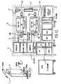
- FIG. 1 The major components of this preferred laser system 2 are identified in FIG. 1 . These include:
- the laser system would preferably include a pulse stretching unit (not shown) to stretch the pulse duration beyond about 12 ns.
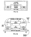
- the optics of both the MO and the PA are mounted on a U-shaped optical table as shown in FIGS. 1A and 1B .
- the U-shaped optical table is kinematically mounted to the base of the laser in the manner described in U.S. Patent No. 5,863,017 .
- Both chambers of the MO and the PA are not mounted on the table but each is supported by three wheels (two on one side and one on the other) on rails supported from the bottom frame of chamber 2. (The wheel and rails are preferably arranged as described in U.S. Patent No. 6,109,574 . This arrangement provides isolation of the optics from chamber caused vibrations.
- a second general layout shown in FIG. 1C is similar to the first general layout described above but including the following features:
- FIG. 1D Portions of a third general layout is shown in FIG. 1D .
- This layout accommodates an embodiment of the present invention which utilizes laser chambers in which the length of the discharge region is about one-half the length of the discharge region in the first two embodiments. That is, the discharge region length is about 26.5 cm as compared to typical length of about 53 cm.
- the resonant cavity of the master oscillator 10(1) is defined by two passes through the discharge region between maximum reflection mirror 10E and an output coupler which is located along with a five prism line selector in LSP 10C.
- the beam makes four passes through the power amplifier 12(1).
- the second pass after reflection from mirrors 15B is through the top half at an angle right to left at an angle of about 4 degrees.
- the third pass after reflection from two mirrors 15C is aligned with the electrodes through the top half of the discharge region and the last pass after reflection from mirrors 15D is aligned with the electrodes through the bottom half of the discharge region. This last pass establishes the power amplifier output beam. It bypasses mirrors 15C and is directed by mirrors (not shown) to the pulse multiplier unit (also not shown).
- the master oscillator 10 shown in FIGS. 1 and 1C is in many ways similar to prior art ArF lasers such as described in the '884 patent and in U.S. Patent No. 6,128,323 and the ArF laser described in U.S. Patent Application Serial No. 09/854,097 except the chamber and resonant cavity optics are configured for F2 laser operation at the 157.63 nm spectral range. Also, the output pulse energy is about 0.1 mJ to 1.0 mJ instead of about 5 mJ. However, major improvements over the '323 laser are provided to permit operation at 4000 Hz and greater.
- the master oscillator may be optimized for spectral performance including line width control.
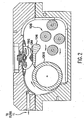
- the master oscillator comprises discharge chamber 10A as shown in FIG.
- FIG. 1 , FIG. 2 and FIG. 3 in which are located a pair of elongated electrodes 10 A2 and 10A3, each about 50 cm long and spaced apart by about 12 mm.
- Anode 10A4 is mounted on flow shaping anode support bar 10A6.
- Four separate finned water cooled heat exchanger units 10A-8 are provided.
- a tangential fan 10A10 is driven by two motors (not shown) for providing a laser gas flow at a velocity of about 80 m/s between the electrodes.
- the chamber includes window units (not shown) with CaF 2 windows positioned at about 47° with the laser beam.
- An electrostatic filter unit having an intake at the center of the chamber, filters a small portion of the gas flow as indicated at 11 in FIG.
- the gain region of the master oscillator is created by discharges between the electrodes through the laser gas which in this embodiment is comprised of about 0.5% F 2 and the rest neon, helium or a combination of helium and neon.
- the gas flow clears the debris of each discharge from the discharge region prior to the next pulse.
- the resonant cavity is created at the output side by an output coupler located in LSP 10C.
- the output coupler is comprised of an uncoated CaF 2 reflecting optic mounted perpendicular to the beam direction so as to reflect about 5% of the laser light at about 157 nm and to pass about 95% of the 157 nm light.
- the opposite boundary of the resonant cavity is a maximum reflection mirror 100 as shown in FIG. 1 .
- the line selection package 10C is described in more detail below with reference to FIG. 16 .
- the main charging capacitor banks for both the master oscillator and the power amplifier are charged in parallel so as to reduce jitter problems.
- pulse energy output from the power amplifier is controlled on a pulse-to-pulse basis by adjustment of the charging voltage. This limits somewhat the use of voltage to control beam parameters of the master oscillator.
- laser gas pressure and F 2 concentration can be easily controlled to achieve desirable beam parameters over a wide range pulse energy. Bandwidth decreases with decreasing F 2 concentration and laser gas pressure.
- the time between discharge and light-out is a function of F 2 concentration (1 ns/kPa), so F 2 concentration may also be changed to vary the timing but this may not be desirable since it could complicate other aspects of laser beam control.
- the power amplifier in each of the three embodiments is comprised of a laser chamber which is very similar to the corresponding master oscillator discharge chamber. Having the two separate chambers allows the pulse energy and integrated energy in a series of pulses (called dose) to be controlled, to a large extent, separately from wavelength and bandwidth. This permits better dose stability. All of the components of the chamber are the same and are interchangeable during the manufacturing process. However, in operation, the gas pressure is preferably substantially lower in the MO as compared to the PA.
- the compression head 12B of the power amplifier as shown in FIG. 1 is also substantially identical in this embodiment to the 10B compression head and the components of the compression head are also interchangeable during manufacture.
- the capacitors of the compression head capacitor bank are more widely positioned for the MO to produce a substantially higher inductance as compared to the PA.
- the electrode spacing in the PA is preferably about 8 mm (as compared to about 12 mm for the MO). This close identity of the chambers and the electrical components of the pulse power systems helps assure that the timing characteristics of the pulse forming circuits are the same or substantially the same so that jitter problems are minimized.
- the power amplifier is configured for a single pass through the discharge region of the power amplifier discharge chamber in the FIG. 1 and FIG. 1C embodiments and for four passages in its FIG. 1D embodiment as described above.
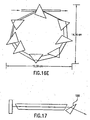
- line selection takes place in LSP 10C using the five-prism line selector shown in FIG. 16 .
- Line selection is preferably downstream of the gain medium of the MO since in these F 2 lasers the gain is very high compared to KrF and ArF lasers.
- the line selected seed beam is reflected upward by mirror 14A and reflected horizontally for one pass through the power amplifier as discussed above.
- the charging voltages preferably are selected on a pulse-to-pulse basis to maintain desired pulse and dose energies.
- F 2 concentration and laser gas pressure can be adjusted in the power amplifier to provide a desired operating range of charging voltage. This desired range can be selected to produce a desired value of dE/dV since the change in energy with voltage is a function of F 2 concentration and laser gas pressure.
- the timing of injections is preferable based on charging voltage.
- the frequency of injections is preferably high to keep laser chamber conditions relatively constant and can be continuous or nearly continuous. Some users of these embodiments may prefer larger durations (such as 2 hours) between F 2 injections.
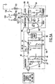
- the basic pulse power circuits are similar to pulse power circuits of prior art excimer laser light sources for lithography. However, separate pulse power circuits downstream of the charging capacitors are provided for each discharge chamber. Preferably a single resonant charger charges two charging capacitor banks connected in parallel to assure that both charging capacitor banks are charged to precisely the same voltage. Important improvements are also provided to regulate the temperature of components of the pulse power circuits. In preferred embodiments the temperatures of the magnetic cores of saturable inductors are monitored and the temperature signals are utilized in a feedback circuit to adjust the relative timing of the discharge in the two chambers. FIGS. 5A and 5B show important elements of a preferred basic pulse power circuit which is used for the MO. The same basic circuit is also used for the PA.
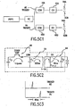
- FIG. 5B A preferred resonant charger system is shown in FIG. 5B .
- the principal circuit elements are:
- This circuit includes switch Q2 and diode D3, together known as a De-Qing switch.
- This switch improves the regulation of the circuit by allowing the control unit to short out the inductor during the resonant charging process. This "de-qing" prevents additional energy stored in the current of the charging inductor, L1, from being transferred to capacitor C 0 .
- Switch Q3 of bleed down circuit 216 will be commanded closed by the control board when current flowing through inductor L1 stops and the voltage on C 0 will be bled down to the desired control voltage; then switch Q3 is opened.
- the time constant of capacitor C o and resistor R3 should be sufficiently fast to bleed down capacitor C o to the command voltage without being an appreciable amount of the total charge cycle.
- the resonant charger can be configured with three levels of regulation control. Somewhat crude regulation is provided by the energy calculator and the opening of switch Q1 during the charging cycle. As the voltage on the CO capacitor banks nears the target value, the de-qing switch is closed, stopping the resonant charging when the voltage on C o is at or slightly above the target value.
- the switch Q1 and the de-qing switch is used to provide regulation with accuracy better than +/- 0.1 %. If additional regulation is required, the third control over the voltage regulation could be utilized. This is the bleed-down circuit of switch Q3 and R3 (shown at 216 in FIG. 5B ) to discharge the CO's down to the precise target value.
- the pulse power system of the MO and the PA of the present invention each utilizes the same basic design ( FIG. 5A ) as was used in the prior art systems.
- FIG. 5A some significant improvements in that basic design were required for the approximate factor of 3 increase in heat load resulting from the greatly increased repetition rate. These improvements are discussed below.
- Solid state switch 46 is an P/N CM 800 HA-34H IGBT switch provided by Powerex, Inc. with offices in Youngwood, Pennsylvania. In a preferred embodiment, two such switches are used in parallel.
- FIG. 6 shows a preferred design of the L o inductor 48.
- four conductors from the two IGBT switches 46B pass through sixteen ferrite toroids 49 to form part 48A an 20,32 cm (8 inch) long hollow cylinder of very high permability material with an ID of about 2.54 cm (1 inch) and an Od of about 3,81 cm (1.5 inch).
- Each of the four conductors are then wrapped twice around an insulating doughnut shaped core to form part 48B.
- the four conductors then connect to a plate which is in turn connected to the high voltage side of the C 1 capacitor bank 52.
- FIG. 8 A preferred sketch of saturable inductor 54 is shown in FIG. 8 .
- the inductor is a single turn geometry where the assembly top and bottom lids 541 and 542 and center mandrel 543, all at high voltage, form the single turn through the inductor magnetic cores.
- the outer housing 545 is at ground potential.
- the magnetic cores are 0,013 mm (0.0005") thick tape wound 50-50% Ni-Fe alloy provided by Magnetics of Butler, Pennsylvania or National Arnold of Adelanto, California. Fins 546 on the inductor housing facilitate transfer of internally dissipated heat to forced air cooling.
- a ceramic disk (not shown) is mounted underneath the reactor bottom lid to help transfer heat from the center section of the assembly to the module chassis base plate.
- FIG. 8 also shows the high voltage connections to one of the capacitors of the C 1 capacitor bank 52 and to a high voltage lead on one of the induction units of the 1:25 step up pulse transformer 56.
- the housing 545 is connected to the ground lead of
- FIGS. 9A and 9B A top and section view of the saturable inductor 64 is shown respectively in FIGS. 9A and 9B .
- flux excluding metal pieces 301, 302, 303 and 304 are added as shown in FIG. 9B in order to reduce the leakage flux in the inductors.
- These flux excluding pieces substantially reduce the area which the magnetic flux can penetrate and therefore help to minimize the saturated inductance of the inductor.
- the current makes five loops through vertical conductor rods in the inductor assembly around magnetic core 307.
- the current enters at 305 travels down a large diameter conductor in the center labeled "1" and up six smaller conductors on the circumference also labeled "1" as shown in FIG. 9A .
- the current then flows down two conductors labeled 2 on the inside, then up the six conductors labeled 2 on the outside then down flux exclusion metal on the inside then up the six conductors labeled 3 on the outside, then down the two conductors labeled 3 on the inside, then up the six conductors labeled 4 on the outside, then down the conductor labeled 4 on the inside.
- the flux exclusion metal components are held at half the full pulsed voltage across the conductor allowing a reduction in the safe hold-off spacing between the flux exclusion metal parts and the metal rods of the other turns.
- the magnetic core 307 is made up of three coils 307A, B and C formed by windings of 0,013 mm (0.0005") thick tape 80-20% Ni-Fe alloy provided by Magnetics, Inc. of Butler, Pennsylvania or National Arnold of Adelanto, California.
- nano-crystoline materials such as VITROPERTM available from VACUUM SCHITELZE GmbH, Germany and FINEMETTTM from Hitachi Metals, Japan could be used for inductors 54 and 64.
- VITROPERTM available from VACUUM SCHITELZE GmbH, Germany
- FINEMETTTM from Hitachi Metals, Japan
- oil leakage from electrical components has been a potential problem.
- oil insulated components are limited to the saturable inductors.
- the saturable inductor 64 as shown in FIG.
- 9B is housed in a pot type oil containing housing in which all seal connections are located above the oil level to substantially eliminate the possibility of oil leakage.
- the lowest seal in inductor 64 is shown at 308 in FIG. 8B . Since the normal oil level is below the top lip of the housing 306, it is almost impossible for oil to leak outside the assembly as long as the housing is maintained in an upright condition.
- Capacitor banks 42, 52, 62 and 82 are all comprised of banks of off-the-shelf capacitors connected in parallel.
- Capacitors 42 and 52 are film type capacitors available from suppliers such as Vishay Roederstein with offices in Statesville, North Carolina or Wima of Germany. Applicants preferred method of connecting the capacitors and inductors is to solder them to positive and negative terminals on special printed circuit board having heavy nickel coated copper leads in a manner similar to that described in U.S. Patent No. 5,448,580 .
- Capacitor bank 62 and 64 is typically composed of a parallel array of high voltage ceramic capacitors from vendors such as Murata or TDK, both of Japan.
- capacitor bank 82 i.e., C p
- C p capacitor bank 82
- C p-1 is comprised of a bank of twenty four 0.40 nF capacitors for a total capacitance of 9.6 nF
- C 1 is a 5.7 ⁇ F capacitor bank
- C o is a 5.3 ⁇ F capacitor bank.
- Pulse transformer 56 is also similar to the pulse transformer described in U.S. Patent Nos. 5,448,580 and 5,313,481 ; however, the pulse transformers of the present embodiment has only a single turn in the secondary winding and 24 induction units equivalent to 1/24 of a single primary turn for an equivalent step-up ratio of 1:24.
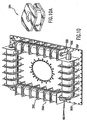
- a drawing of pulse transformer 56 is shown in FIG. 10 .
- Each of the 24 induction units comprise an aluminum spool 56A having two flanges (each with a flat edge with threaded bolt holes) which are bolted to positive and negative terminals on printed circuit board 56B as shown along the bottom edge of FIG. 10 .
- Insulators 56C separates the positive terminal of each spool from the negative terminal of the adjacent spool. Between the flanges of the spool is a hollow cylinder 2,70 cm (1 1/16 inches) long with a 0.875 OD with a wall thickness of about 0,78 mm (1/32 inch). The spool is wrapped with 2,54 cm (one inch) wide, 17,78 ⁇ m (0.7 mil) thick MetglasTM 2605 S3A and a 2,54 ⁇ m (0.1 mil) thick mylar film until the OD of the insulated MetglasTM wrapping is 5,70 cm (2.24 inches). A prospective view of a single wrapped spool forming one primary winding is shown in FIG. 10A .
- the secondary of the transformer is a single OD stainless steel rod mounted within a tight fitting insulating tube of PTFE (Teflon®).
- the winding is in four sections as shown in FIG. 10 .
- the low voltage end of stainless steel secondary shown as 56D in FIG. 10 is tied to the primary HV lead on printed circuit board 56B at 56E, the high voltage terminal is shown at 56F.
- the transformer assumes an auto-transformer configuration and the step-up ratio becomes 1:25 instead of 1:24.
- an approximately -1400 volt pulse between the + and - terminals of the induction units will produce an approximately -35,000 volt pulse at terminal 56F on the secondary side.
- This single turn secondary winding design provides very low leakage inductance permitting extremely fast output rise time.
- the Cp capacitor 82 is comprised of a bank of thirty-three 0.3 nf capacitors mounted on top of the chamber pressure vessel.
- an ArF laser is operated with a lasing gas made up of 3.5% argon, 0.1% fluorine, and the remainder neon.
- the electrodes are about 71,12 cm (28 inches) long which are separated by about 1,27 cm to 2,54 cm (0.5 to 1.0 inch) preferably about 1,60 cm (5/8 inch). Preferred electrodes are described below.
- the top electrode is referred to as the cathode and the bottom electrode is connected to ground as indicated in FIG. 5 and is referred to as the anode.
- ArF, KrF and F 2 electric discharge lasers the electric discharge lasts only about 50 ns (i.e., 50 billionths of a second). This discharge creates a population inversion necessary for lasing action but the inversion only exists during the time of the discharge. Therefore, an important requirement for an injection seeded ArF, KrF or F 2 laser is to assure that the seed beam from the master oscillator passes through discharge region of the power amplifier during the approximately 50 billionth of a second when the population is inverted in the laser gas so that amplification of the seed beam can occur.
- An important obstacle to precise timing of the discharge is the fact that there is a delay of about 5 microseconds between the time switch 42 (as shown in FIG.
- Applicants have developed electrical pulse power circuits that provide timing control of the discharges of the two discharge chambers within a relative accuracy of less than about 2 ns (i.e., 2 billionths of a second).
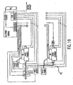
- a block diagram of the two circuits are shown in FIG. 4 .
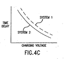
- Applicants' preferred solution to this problem is to charge the charging capacitor of both the MO and the PA in parallel from the single resonant charger 7 as indicated in FIG. 1 and FIG. 4 and as described above. It is also important to design the two pulse compression/amplification circuits for the two systems so that time delay versus charging voltage curves match as shown in FIG. 4A . This is done most easily by using to the extent possible the same components in each circuit.
- Applicants have designed pulse power components for both discharge chambers with similar components and have confirmed that the time delay versus voltage curves do in fact track each other as indicated in FIG. 4A .
- Applicants have confirmed that over the normal operating range of charging voltage, there is a substantial change in time delay with voltage but the change with voltage is virtually the same for both circuits.
- both charging capacitors charged in parallel charging voltages can be varied over a wide operating range without changing the relative timing of the discharges.
- Temperature control of electrical components in the pulse power circuit is also important since temperature variations can affect pulse compression timing (especially temperature changes in the saturable inductors). Therefore, a design goal is to minimize temperature variations and a second approach is to monitor temperature of the temperature sensitive components and using a feedback control adjust the trigger timing to compensate. Controls can be provided with a processor programmed with a learning algorithm to make adjustments based on historical data relating to past timing variations with known operating histories. This historical data is then applied to anticipate timing changes based on the current operation of the laser system.
- the triggering of the discharge for each of the two chambers is accomplished separately utilizing for each circuit a trigger circuit such as one of those described in U.S. Patent No. 6,016,325 .
- These circuits add timing delays to correct for variations in charging voltage and temperature changes in the electrical components of the pulse power so that the time between trigger and discharge is held as constant as feasible.
- the two circuits are basically the same, the variations after correction are almost equal (i.e., within about 2 ns of each other).
- performance of this preferred embodiment is greatly enhanced if the discharge in the power amplifier occurs about 40 to 50 ns after the discharge in the master oscillator. This is because it takes several nanoseconds for the laser pulse to develop in the master oscillator and another several nanoseconds for the front part of the laser beam from the oscillator to reach the amplifier and because the rear end of the laser pulse from the master oscillator is at a much narrower bandwidth than the front part. For this reason, separate trigger signals are provided to trigger switch 46 for each chamber. The actual delay is chosen to achieve desired beam quality based on actual performance curves such as those shown in FIGS. 6C, D and E . The reader should note, for example, that narrower bandwidth and longer pulses can be obtained at the expense of pulse energy by increasing the delay between MO trigger and PA trigger.
- the timing of the discharges can be monitored on a pulse-to-pulse basis and the time difference can be used in a feedback control system to adjust timing of the trigger signals closing switch 42.
- the PA discharge would be monitored using a photocell to observe discharge fluorescence (called ASE) rather than the laser pulse since very poor timing could result if no laser beam being produced in the PA.
- ASE discharge fluorescence
- the MO either the ASE or the seed laser pulse could be used.
- the pulse timing can be increased or decreased by adjusting the bias currents through inductors L B1 L B2 and L B3 which provide bias for inductors 48, 54 and 64 as shown in FIG. 5 .
- Other techniques could be used to increase the time needed to saturate these inductors.
- the core material can be mechanically separated with a very fast responding PZT element which can be feedback controlled based on a feedback signal from a pulse timing monitor.
- An adjustable parasitic load could be added to either or both of the pulse power circuits downstream of the CO's.
- Charging voltage and inductor temperature signals in addition to the pulse timing monitor signals can be used in feedback controls to adjust the bias voltage or core mechanical separation as indicated above in addition to the adjustment of the trigger timing as described above.
- This process may be repeated for many hours, but will be interrupted from time-to-time for periods longer than 1 minute.
- the length of down times will affect the relative timing between the pulse power systems of the MO and the PA and adjustment may be required in the trigger control to assure that the discharge in the PA occurs when the seed beam from the MO is at the desired location.
- the laser operator can adjust the trigger timing (accurate to within about 2 ns) to achieve best performance.
- a laser control processor is programmed to monitor the timing and beam quality and adjust the timing automatically for best performance.
- Timing algorithms which develop sets of bin values applicable to various sets of operating modes are utilized in preferred embodiments of this invention. These algorithms are in preferred embodiments designed to switch to a feedback control during continuous operation where the timing values for the current pulse is set based on feedback data collected for one or more preceding pulse (such as the immediately preceding pulse).
- Timing algorithms such as those discussed above work very well for continuous or regularly repeated operation. However, the accuracy of the timing may not be good in unusual situations such as the first pulse after the laser is off for an unusual period of time such as 5 minutes. In some situations imprecise timing for the first one or two pulses of a burst may not pose a problem.
- a preferred technique is to preprogram the laser so that the discharges of the MO and the PA are intentionally out of sequence for one or two pulses so that amplification of the seed beam from the MO is impossible. For example, laser could be programmed to trigger the discharge of the PA 80 ns prior to the trigger of the MO.
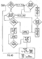
- FIGS. 4D , 4D1, 4E and 4E1 are flow charts showing possible control algorithms using these techniques.
- water cooling of pulse power components is provided in addition to the normal forced air cooling provided by cooling fans inside the laser cabinet in order to support operation pulse rates of 4 KHz or greater.
- FIG. 11 a water cooled saturable inductor 54A is provided as shown in FIG. 11 which is similar to the inductor 54 shown in FIG. 8 except the fins of 54 are replaced with a water cooled jacket 54A1 as shown in FIG. 11 .
- the cooling line 54A2 is routed within the module to wrap around jacket 54A1 and through aluminum base plate where the IGBT switches and Series diodes are mounted. These three components make up the majority of the power dissipation within the module.
- Other items that also dissipate heat are cooled by forced air provided by the two fans in the rear of the module.
- the jacket 54A1 is held at ground potential, there are no voltage isolation issues in directly attaching the cooling tubing to the reactor housing. This is done by press-fitting the tubing into a dovetail groove cut in the outside of the housing as shown at 54A3 and using a thermally conductive compound to aid in making good thermal contact between the cooling tubing and the housing.
- the IGBT switches "float" at high voltage, they are mounted on an aluminum base electrically isolated from the switches by a 1,59 mm (1/16 inch) thick alumina plate.
- the aluminum base plate which functions as a heat sink and operates at ground potential and is much easier to cool since high voltage isolation is not required in the cooling circuit.
- FIG. 7 A drawing of a water cooled aluminum base plate is shown in FIG. 7 .
- the cooling tubing is pressed into a groove in an aluminum base on which the IGBT's are mounted.
- thermally conductive compound is used to improve the overall joint between the tubing and the base plate.
- the series diodes also "float" at high potential during normal operation.
- the diode housing typically used in the design provides no high voltage isolation.
- the diode "hockey puck” package is clamped within a heat sink assembly which is then mounted on top of a ceramic base that is then mounted on top of the water-cooled aluminum base plate.
- the ceramic base is just thick enough to provide the necessary electrical isolation but not too thick to incur more than necessary thermal impedance.
- the ceramic is 1,59 mm (1/16") thick alumina although other more exotic materials, such as beryllia, can also be used to further reduce the thermal impedance between the diode junction and the cooling water.
- a second embodiment of a water cooled commutator utilizes a single cold plate assembly which is attached to the chassis baseplate for the IGBT's and the diodes.
- the cold plate may be fabricated by brazing single piece nickel tubing to two aluminum "top” and “bottom” plates.
- the IGBT's and diodes are designed to transfer their heat into the cold plate by use of the previously mentioned ceramic disks underneath the assembly.
- the cold plate cooling method is also used to cool the IGBT and the diodes in the resonant charger. Thermally conductive rods or a heat pipe can also be used to transfer heat from the outside housing to the chassis plate.
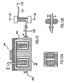
- the water-cooled compression head is similar in the electrical design to a prior art air-cooled version (the same type ceramic capacitors are used and similar material is used in the reactor designs). The primary differences in this case are that the module must run at higher rep-rates and therefore, higher average power. In the case of the compression head module, the majority of the heat is dissipated within the modified saturable inductor 64A. Cooling the subassembly is not a simple matter since the entire housing operates with short pulses of very high voltages. The solution to this issue as shown in FIGS. 12, 12A and 12B is to inductively isolate the housing from ground potential. This inductance is provided by wrapping the cooling tubing around two cylindrical forms that contain a ferrite magnetic core. Both the input and output cooling lines are coiled around cylindrical portions of a ferrite core formed of the two cylindrical portions and the two ferrite blocks as shown in FIGS. 12, 12A and 12B .
- the ferrite pieces are made from CN-20 material manufactured by Ceramic Magnetics, Inc. of Fairfield, New Jersey.
- a single piece of copper tubing (4,75 mm (0.187") diameter) is press fit and wound onto one winding form, around the housing 64A1 of inductor 64A and around the second winding form. Sufficient length is left at the ends to extend through fittings in the compression head sheet metal cover such that no cooling tubing joints exist within the chassis.
- the inductor 64A comprises a dovetail groove as shown at 64A2 similar to that used in the water-cooled commutator first stage reactor housing. This housing is much the same as previous air-cooled versions with the exception of the dovetail groove.
- the copper cooling-water tubing is press fit into this groove in order to make a good thermal connection between the housing and the cooling-water tubing. Thermally conductive compound is also added to minimize the thermal impedance.
- inductor 64A The electrical design of inductor 64A is changed slightly from that of 64 shown in FIGS 9A and 9B .
- Inductor 64A provides only two loops (instead of five loops) around magnetic core 64A3 which is comprised of four coils of tape (instead of three).
- bias current is supplied by a dc-dc converter in the commutator through a cable into the compression head.
- the current passes through the "positive" bias inductor L B2 and is connected to the Cp-1 voltage node.
- the current then splits with a portion returning to the commutator through the HV cable (passing through the transformer secondary to ground and back to the dc-dc converter).
- the other portion passes through the compression head reactor Lp-1 (to bias the magnetic switch) and then through the cooling-water tubing "negative" bias inductor L B3 and back to ground and the dc-dc converter.
- the "positive" bias inductor L B2 is made very similarly to the “negative” bias inductor L B3 .
- the same ferrite bars and blocks are used as a magnetic core.
- two 3,18 mm (0.125") thick plastic spacers are used to create an air gap in the magnetic circuit so that the cores do not saturate with the dc current.
- 18 AWG teflon wire is wound around the forms.
- three of the pulse power electrical modules utilize blind mate electrical connections so that all electrical connections to the portions of the laser system are made merely by sliding the module into its place in the laser cabinet.
- These are the AC distribution module, the power supply module and the resonant charges module.
- a male or female plug on the module mates with the opposite sex plug mounted at the back of the cabinet.
- two approximately 7,62 cm (3-inch) end tapered pins on the module guide the module into its precise position so that the electrical plugs properly mate.
- the blind mate connectors such as AMP Model No. 194242-1 are commercially available from AMP, Inc. with offices in Harrisburg, Pennsylvania.
- connectors are for the various power circuits such as 208 volt AC, 400 volt AC, 1000 Volt DC (power supply out and resonant charges in) and several signal voltages. These blind mate connections permit these modules to be removed for servicing and replacing in a few seconds or minutes. In this embodiment blind mate connections are not used for the commutator module the output voltage of the module is in the range of 20 to 30,000 volts. Instead, a typical high voltage connector is used.
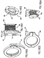
- FIGS. 14 and 15 show details of an improved discharge configuration utilized in preferred embodiments of the present invention.
- This configuration includes an electrode configuration that Applicants call a blade-dielectric electrode.
- the anode 540 comprises a blunt blade shaped electrode 542 with dielectric spacers 544 mounted on both sides of the anode as shown to improve the gas flow in the discharge region.
- the spacers are attached to anode support bar 546 with screws at each end of the spacers beyond the discharge region. The screws allow for thermal expansion slippage between the spacers and the bar.
- the anode is 67,06 cm (26.4 inches) long and 1,12 cm (0.439 inches) high. It is 0,72 cm (0.284 inches) wide at the bottom and 3,58 mm 0.141 inches) wide at the top.
- the anode is comprised of a copper based alloy preferably C36000, C95400, or C19400.
- Cathode 541 has a cross section shape as shown in FIG. 13A .
- a preferred cathode material is C36000. Additional details of this blade dielectric configuration are provided in U.S. Patent Application Serial No. 09/768,753 .
- the current return 548 in this configuration is comprised of a whale bone shaped part with 27 ribs equally spaced along the length of electrode 542, the cross section of which is shown in FIG. 13A (1) .
- the current return is fabricated from sheet metal and the whale-bone ribs (each having cross-section dimensions of about 3,81 mm (0.15 inch) x 2,29 mm (0.09 inch)) are twisted so that the long dimension of each rib is in the direction of current flow.
- FIG. 13A2 An alternative dielectric spacer design for the anode is shown in FIG. 13A2 to improve flow even more.
- the spacers mate more perfectly with the flow shaping anode support bar to provide a better gas flow path. Applicants call this their "fast back" blade dielectric anode design.
- a second preferred pulse power circuit is shown in FIGS. 5C1, 5C2 and 5C3 .
- This circuit is similar to the one described above but utilizes a higher voltage power supply for charging C 0 to a higher value.
- a high voltage pulse power supply unit operating from factory power at 230 or 460 volts AC, is power source for a fast charging resonant charger as described above and designed for precise charging two 2.17 ⁇ F at frequencies of 4000 to 6000 Hz to voltages in the range of about 1100 V to 2250 V.
- the electrical components in the commutator and compression head for the master oscillator are as identical as feasible to the corresponding components in the power amplifier. This is done to keep time responses in the two circuits as identical as feasible.
- Switches 46 are banks of two IGBT switches each rated at 3300 V and arranged in parallel.
- the C 0 capacitor banks 42 is comprised of 128 0.068 ⁇ F 1600 V capacitors arranged in 64 parallel legs to provide the 2.17 ⁇ F C 0 bank.
- the C 1 capacitor banks 52 are comprised of 136 0.068 ⁇ F 1600 V capacitors arranged in 68 parallel legs to provide a bank capacitance of 2.33 ⁇ F.
- the C p-1 and C p capacitor banks are the same as those described above with reference to FIG. 5 .
- the 54 saturable inductors are single turn inductors providing saturated inductance of about 3.3 nH with five cores comprised of 1,27 cm (0.5 inch) thick 50%-50% Ni-Fe with 4.9 inch OD and 9,65 cm (3.8 inch) ID.
- the 64 saturable inductors are two turn inductors providing saturated inductance of about 38 nH each comprised of 5 cores 1,27 cm (0.5 inch) thick made with 80%-20% Ni-Fe with an OD of 12,7 cm (5 inches) and an ID of 5,79 cm (2.28 inches).
- Trigger circuits are provided for closing IGBT's 46 with a timing accuracy of two nanoseconds.
- the master oscillator is typically triggered about 40 ns prior to the triggering of the IGBT 46 for power amplifier. However, the precise timing is preferably determined by feedback signals from sensors which measure the timing of the output of the master oscillator and the power amplifier discharge.
- the output pulse length measured in tests conducted by Applicants on these F 2 lasers is in the range of about 12 ns and is to some extent a function of the relative timing of the two discharges. A longer pulse length (other things being equal) can increase the lifetime of optical components of lithography equipment.
- the relative time between discharges can be optimized for pulse length.
- the pulse power circuits of both the MO and the PA could be optimized for longer pulses using techniques such as those described in U.S. Patent Application Serial No. 09/451,995 .
- An optical pulse multiplier system such as one of those described in U.S. Patent No. 6,067,311 , could be added downstream of the PA to reduce the intensity of individual pulses.
- a preferred pulse multiplier unit also called a pulse stretcher
- This pulse multiplier could be made a part of the beam path to lens components of a lithography tool.
- the chamber could be made longer and the electrodes could be configured to produce traveling wave discharges designed for longer pulse lengths.
- a preferred pulse multiplier unit is shown in FIG. 22A .
- Light beam 20 from laser 50 hits the beam splitter 22.
- Beam splitter has a reflectivity of about 40%. About 40% of the light reflects a first portion of the output beam 30. The rest of the incoming beam transmits through the beam splitter 22 as beam 24. The beam is reflected back at a small angle by a mirror 26, which is a spherical mirror with the focal length equal the distance from beam splitter 22 to the mirror. So, the beam is focused to a point 27 near the beam splitter 22 but missing it slightly. This beam spreads again and is now reflected by mirror 28, which is also a spherical mirror with the focal length equal the distance from this mirror to point 27.
- the mirror 28 reflect the beam back at a small angle and also collimates the reflected beam.
- This reflected beam 32 propagates to the right and is reflected by mirror 29 to beam splitter 22 where about 60% of the beam is transmitted through beam splitter 22 to merge into and become the second portion of output beam 30.
- a portion (about 40%) of beam 34 is reflected by the beam splitter 22 in the direction of beam 24 for a repeat of the trip of beam 32.
- a short input pulse is split into several portions, so that total duration of the beam is increased and its peak intensity is decreased.
- Mirrors 26 and 28 create a relay system which images the portions of the outcoming beam onto each other. Because of that imaging, each portion of the output beam is virtually the same.
- FIG. 22B1 shows the pulse profile of a typical pulse produced by an ArF excimer laser. (These results can be applied to an F 2 laser except the un-multiplied pulse for the F 2 laser is about 12 ns instead of about 18 ns for the ArF laser.)
- FIG. 22B2 shows the simulated output pulse profile of a similar ArF laser pulse after being spread in a pulse stretcher built in accordance with FIG. 22A .
- FIG. 22C shows a layout similar to the FIG. 22A layout but with an additional delay path.
- the first beam splitter 22A is designed for a reflection of 25 percent and the second beam splitter 22B is designed for a reflection of 40 percent.
- the resulting beam shape produced by computer simulation is shown in FIG. 22D .
- the T is for this stretched pulse is about 73.2 ns.
- the portions of the beam is transmitted through beam splitter 22B are flipped in orientation when they return and are joined into exit beam 30. This reduces significantly the spatial coherence of the beam.
- the pulse stretcher unit could be installed in the back of vertical optical table 11 as suggested above or it could be installed on top of the table or even inside of it.
- Pulse energy and dose energy are preferably controlled with a feedback control system and algorithm such as that described above.
- the pulse energy monitor can be at the laser as closer to the wafer in the lithography tool.
- charging voltages are chosen to produce the pulse energy desired.
- both the MO and the PA are provided with the same charging voltage since the CO's are charged in parallel.
- the present invention provides a laser system capable of much greater pulse energy and output power than prior art single chamber high repetition rate gas discharge lasers.
- the master oscillator determines the wavelength and the bandwidth and the power amplifier primarily controls the pulse energy.
- the pulse energy needed for an efficient seeding of the power amplifier is can be as low as a small fraction of a mJ. Since the master oscillator type of laser is easily capable of producing 5 mJ pulses, it has energy to spare. This additional pulse energy provides opportunities for using certain techniques for improving beam quality which are not particularly energy efficient.
- Spatial filtering is effective at reducing the integrated 95% bandwidth.
- all direct spatial filtering techniques previously proposed required at least concentrating the beam and in most cases actually focusing the beam.
- all previous designs required multiple optical elements.
- a simple, compact spatial filter, that does not require a focused beam, would be more readily adaptable for incorporation inside the laser resonator if spatial filtering is desired.
- a preferred filter is a single prism approximately 5,08 cm (2 inches) in length.
- the entrance and exit faces of the prism are parallel to each other and normal to the incident beam. Two other faces would be parallel to each other but orientated at an angle equal to the critical angle with respect to the entrance and exit faces.
- the critical angle in CaF 2 is 39.89 degrees.
- the only coatings required would be normal incidence anti-reflection coatings on the entrance and exit faces of the prism.
- the spatial filter would work in the following manner.
- the beam would enter at normal incidence to the entrance face of the prism.
- the beam would then propagate to the critical angle face of the prism. If the beam was collimated all rays would be incident at the critical angle at this second face. However, if the beam if diverging or converging some of the rays will strike this face at angles greater than and less than the critical angle. All rays striking this face at or greater than the critical angle will be reflected at 100%. Rays striking this face at an angle less than the critical angle will be reflected at values less than 100% and will be attenuated. All rays that are reflected will be incident at the opposite face of the prism at the same angle where they will also be attenuated by the same amount.
- FIG. 23B shows the design of the spatial filter.
- the input and output faces of the prism are 1,27 cm (1 ⁇ 2 inch).
- the critical angle faces are about 5,08 cm (2 inches).
- the input beam width is 2.6 mm and represents the width of the beam in the short axis.
- the prism would have a height of 2,54 cm (1 inch) in the plane of the drawing.
- the figure shows three sets of rays.
- the first set of rays is collimated and strikes the surfaces at the critical angle. These are the green rays.
- a second set of rays is incident at the surface less than the critical angle and is terminated at the first reflection. They are the blue rays.
- These rays are more visible in the magnified section. They represent the rays that are attenuated on the first pass.
- the final set of rays is incident at an angle greater than the critical angle. These rays propagate through the entire first pass but are terminated at the first reflection of the second pass. They represent the ray
- a cylindrical refractive telescope is provided between the output of the master oscillator and the input of the power amplifier. This controls the horizontal size of the beam entering the power amplifier.
- This telescope can also be designed using well known techniques to control the horizontal divergence.
- pulse energy is monitored controlled on a pulse to pulse basis with feedback from a fast photodiode energy monitor.
- pulse-by-pulse monitoring of wavelength and bandwidth are not provided since the natural centerline wavelength and bandwidth of the major F2 line is relatively invariable. If desired, however, both wavelength and bandwidth could be monitored generally in the same manner as in prior art excimer lasers but at the 157 nm wavelength range.
- power monitors should be provided at the output of the master oscillator, after the power amplifies and after the pulse multiplies.
- a p-cell should also be provided for monitoring any back reflections into the master oscillator. Such back reflections could be amplified in the oscillator and damage the master oscillator optical components.
- the back reflection signal from the back reflection monitor is used to shut the laser down if a danger threshold is exceeded.
- the system should be designed to avoid glint in the beam path that might cause any significant back reflection.
- wavelength and bandwidth metrology components are subject to radiation damage so Applicants recommend that these measurements be made periodically rather than on a pulse to pulse basis. For example, wavelength and bandwidth could be monitored for 30 pulses once each 10 minute period.
- the metrology components for the F2 lasers should have lifetimes at least comparable to KrF and ArF lasers. To accomplish this a shutter should be provided for the wavemeter to block the beam access to the wavelength and bandwidth metrology components.
- the optical equipment in these units measure pulse energy, wavelength and bandwidth. These measurements are used with feedback circuits to maintain pulse energy and wavelength within desired limits.
- a small portion of the laser beam is reflected to an energy detector which comprises a very fast photo diode which is able to measure the energy of individual pulses occurring at the rate of 4000 pulses per second.
- the pulse energy is about 10 mJ
- the output of detector 69 is fed to a computer controller which uses a special algorithm to adjust the laser charging voltage to precisely control the pulse energy of future pulses based on stored pulse energy data in order to limit the variation of the energy of individual pulses and the integrated energy of bursts of pulses.
- the pulse energy of subsequent pulses are controlled to maintain desired pulse energies and also desired total integrated dose of a specified number of pulses all as described in U.S. Patent No. 6,005,879 , Pulse Energy Control for Excimer Laser.
- the strongest of the natural F2 resonant lines is selected using a five-prism line selector as shown in FIGS. 16A and B .
- These five prisms 112 A-E are precisely mounted on a single prism plate not shown which is located in LSP 10C as shown in FIG. 1 .
- This LSP is located downstream of the master oscillator a short distance downstream of the master oscillator output coupler.
- Each of the five prisms are 65 degree (apex angle) prisms and are arranged horizontally as shown in FIG. 16A .
- the angle of incidence of the prisms for this particular embodiment are as follows for prisms 112A through E respectively: 79.6°, 61.4°, 47.7°, 71.7° and 42.1°. (Many other prism configurations could provide similar results.)
- Mirror 114B is positioned to reflect the beam upward to mirror 114C which is positioned to reflect the beam through an aperture (not shown) into the discharge region of the power amplifier as shown 12A as shown in FIG. 1 .
- the five-prism line selector produces an angular spread of 10.56 milli-radians between the 157.63nm and the 157.52 nm F 2 lines which produces a spatial separation of about 5.5 mm at a distance of about 0.5 meters downstream at the aperture in front of the power amplifier. This spread is easily sufficient to separate out the 157.52 nm line.
- FIG. 16E An alternate prism line selection unit is shown in FIG. 16E .
- This is a ring configuration. It can be inserted in the beam path without disturbing the beam direction.
- the ring is comprised of four 45° apex angle prisms and four 65° angle prisms.
- a Lyot filter uses the dispersion of the birefringence of a non-isotropic crystalline material, such as MgF 2 , to rotate the polarization of the light depending on the wavelength.
- a non-isotropic crystalline material such as MgF 2
- MgF 2 non-isotropic crystalline material
- Discrimination of these rotated waves can be achieved by polarization dependent optic elements, such as the Brewster windows of the F 2 laser's gas discharge chamber.
- a single Brewster window of CaF 2 material will show a 1:0.7 ratio of intensity transmission between p-polarized and s-polarized waves respectively.
- the losses for the s-polarized waves are due to reflections on the surfaces. Since the chamber has two windows these values have to be taken to the 4 th potency to give the correct full round trip ratio of 1:0.24. Optimum discrimination of one of the lines is achieved if the total polarization rotation angle on a double pass through the crystal is exactly 90 degrees. This will be achieved by adjusting the thickness of the crystal to the characteristic quarter wave plate thickness. However, the wavelength of the other line should not undergo such rotation, in fact the total polarization rotation at this wavelength should be a whole multiple of 180 degree (half wave plate) so that the discriminating elements would not affect the transmission of this wave. Thus, the combination of the dispersive birefringent crystal, the polarizing elements (Brewster windows) and the back mirror (for the second pass back through the crystal) suppresses one of the wavelengths while the other remains unaffected.
- FIG. 16C1 shows schematically a line selected F2 laser system with intra-cavity Lyot filter.
- the resonator is built of high reflective mirror 116A, the birefringent dispersive crystal 116B, the (chamber) Brewster windows 116C and 116D and the output coupling mirror 116E which is partially reflecting.
- the optical gain is generated within the gas discharge in chamber 116F.
- FIG. 16C2 shows another design, which uses one or several additional Brewster elements 116G to increase the discrimination between both p- and s-polarization.
- FIG. 16C3 shows an alternative design for the high reflecting mirror and the crystal. In fact, both elements can be combined applying the dielectric reflective coating 116H directly on the rear side of the crystal 116B, which will reduce the amount of optical elements required.
- FIG. 1 provides for line selection downstream of the master oscillator with no line selection within the resonant cavity of the master oscillator.
- Alternate embodiments could include line selection within the resonant cavity such as at the rear of the laser chamber 10A. This line selector could be in addition to or in lieu of the FIG. 16A . line selector.
- a preferred design of such a line selector comprises five CaF or MgF prisms oriented such that entering and leaving the prisms are at Brewster angle (about 57.3 degrees). This permits use of prisms without anti-reflection coatings.
- FIG. 16D A sketch showing this line selection approach is shown in FIG. 16D . This arrangement includes five prisms 118A with apex angles equal to 2X (90o - ⁇ B ) where ⁇ B is Brewster's angle.
- the reflection optic 118B is a half prism with a maximum reflection coating 118C on the rear side.
- novel features here are to avoid the need for an anti-reflection coating on the incidence face by using Brewster's angle (providing zero reflection coefficient for appropriately polarized laser) and placing the reflective coating directly on the rear surface of the optic.
- the output coupler of gas discharge lasers configured as oscillators is typically a partially reflecting mirror which is usually a wedge shaped optical element with one surface oriented transverse to the beam path and coated to reflect a desired portion of the beam and transmit the remaining portion.
- the other surface is often coated with an anti-reflection coating and may be oriented as an angle other than transverse to the beam path so that any reflections from this surface is not returned to the gain region.
- the output coupler 120 is prism shaped.
- the front surface (closest to the gain region) is oriented for the lowest loss angle (for p-polarization) while the second surface is orthogonal to the refracted laser beam to provide the reflected beam for amplification.
- This design eliminates the need for an AR coating and also provides some additional spectral separation due to dispersions.
- the prism is comprised of CaF 2 with an apex angle of 32.7 degrees and an angle of incidence of 57.2 degrees. In this preferred embodiment, there is no coating on the second surface and the approximately 4.7 percent Fresnel reflection provides sufficient reflection for the master oscillator.
- the beam direction monitor is a split detector, also known as a bi-cell detector or segmented detector. This type of detector has two distinct photosensitive elements separated by a small gap. The ratio of the outputs of the two elements is a measure of the beam direction.
- the beam direction control mechanism can be a pivot mirror preferably in the line selection package 10C in FIG. 1 . Alternatively, one of the prisms in the line selector unit shown in FIG.
- the driver producing the pivot preferably is a piezoelectric driver or it could be a voice coil or a stepper motor drive unit or any of other similar drive units.
- Controls for the direction control mechanism should preferably include a processor programmed with an appropriate feedback algorithm and also additional electronic control and software permitting operator adjustment of the beam direction.
- the beam direction is monitored by a split detector as discussed above and a feedback signal regulates the pressure in the LSP by controlling a purge gas flow valve.
- Another approach is to use a temperature sensor to provide a feedback signal.
- the preferred embodiment of this invention has a gas control module as indicated in FIG. 1 and it is configured to fill each chamber with appropriate quantities of laser gas.
- appropriate controls and processor equipment is provided to maintain continuous flow of gas into each chamber so as to maintain laser gas concentrations constant or approximately constant at desired levels. This may be accomplished using techniques such as those described in U.S. Patent No. 6,028,880 or U.S. Patent No. 6,151,349 or U.S. Patent No. 6,240,117 .
- Another technique for providing continuous flow of laser gas into the chambers which Applicants call its binary fill technique is to provide a number (such as 5) fill lines each successive line orificed to permit double the flow of the previous line with each line having a shut off valve.
- the lowest flow line is orificed to permit minimum equilibrium gas flow.
- Almost any desired flow rate can be achieved by selecting appropriate combinations of valves to be opened.
- a buffer tank is provided between the orificed lines and the laser gas source which is maintained at a pressure at about twice the pressure of the laser chambers.
- the two chambers and the laser optics are mounted on a vertically oriented optical table.
- the table is preferably supported in the laser frame with a three-point kinematic mount.
- FIG. 1C1 One preferred embodiment arrangement is shown in FIG. 1C1 .
- Metal straps are provided on table 11 at locations A, B, and C where the table is mounted to the laser frame 4 (not shown in FIG. 1C1 ).
- a swivel joint is provided at location A which anchors the table but permits it to swivel.
- a ball and V-groove is provided at location B which restricts rotation in the plane of the bottom surface of the table and rotation in the plane of the table front surface.
- a ball and slot groove is provided at location C which restricts rotation around the A-B axis.
- Preferred embodiments are designed to operate at pulse repetition rates of 4000 pulses per second. Clearing the discharge region of discharge affected gas between pulses requires a gas flow between the electrodes 18A and 20A of up to about 67 m/s. To achieve these speeds, the diameter of tangential fan unit has been set at 12,7 cm (5 inches) (the length of the blade structure is 66,04 cm (26 inches)) and the rotational speed has been increased to about 3500 rpm. To achieve this performance the embodiment utilizes two motors which together deliver up to about 4 kw of drive power to the fan blade structure. At a pulse rate of 4000 Hz, the discharge will add about 12 kw of heat energy to the laser gas. To remove the heat produced by the discharge along with the heat added by the fan four separate water cooled finned heat exchanger units 58A are provided. The motors and the heat exchangers are described in detail below.
- a preferred embodiment of the present invention utilizes four firmed water cooled heat exchangers 58A shown generally in FIG. 4 . Each of these heat exchangers is somewhat similar to the single heat exchangers shown at 58 in FIG. 1 having however substantial improvements.
- FIG. 21 A cross sectional drawing of one of the heat exchangers is shown in FIG. 21 .
- the middle section of the heat exchanger is cut out but both ends are shown.
- FIG. 21A shows an enlarged view of the end of the heat exchanger which accommodates thermal expansion and contraction.
- the components of the heat exchanger includes a finned structure 302 which is machined from solid copper (CU 11000) and contains twelve fins 303 per 2,54 cm (inch). Water flow is through an axial passage having a bore diameter of 0,84 cm (0.33 inch).
- a plastic turbulator 306 located in the axial passage prevents stratification of water in the passage and prevents the formation of a hot boundary layer on the inside surface of the passage.
- a flexible flange unit 304 is a welded unit comprised of inner flange 304A, bellows 304B and outer flange 304C.
- the heat exchanger unit includes three c-seals 308 to seal the water flowing in the heat exchanger from the laser gas.
- Bellows 304B permits expansion and contraction of the heat exchanger relative to the chamber.
- a double port nut 400 connects the heat exchanger passage to a standard 7,99 mm (5/16 inch) positional elbow pipe fitting which in turn is connected to a water source.
- O-ring 402 provides a seal between nut 400 and finned structure 302. In preferred embodiments cooling flow direction in two of the units is opposite the other two minimizing axial temperature gradients.
- the turbulator is comprised of four off-the-shelf, long in-line mixing elements which are typically used to mix epoxy components and are available from 3M Corporation (Static Mixer, Part No. 06-D1229-00).
- the in-line mixers are shown at 306 in FIG. 21 and 21A .
- the in-line mixers force the water to flow along a generally helical path which reverses its clockwise direction about every pitch distance (which is 7,62 mm (0.3 inch)).
- the turbulator substantially improves heat exchanger performance. Tests by Applicants have shown that the addition of the turbulator reduces the required water flow by a factor of roughly 5 to maintain comparable gas temperature conditions.
- gas flow into and out of the discharge region has been greatly improved over prior art laser chambers.
- the region upstream of the discharge and adjacent to the exit of the cross flow fan is shaped to form a smooth transition from a large cross section to the small cross section of the discharge.
- the cross section of the region directly downstream of the discharge increases smoothly for the small value of the discharge to a much greater value before the gas is forced to turn 90° into the heat exchangers.
- This arrangement minimizes the pressure drop and associated turbulence caused by high velocity flow over sharp steps.
- Providing this smooth gradually expanding flow path in the direction away from the laser also reduces adverse acoustic effects resulting from acoustic waves from a pulse reflecting back to the discharge region at the time of a subsequent pulse.
- This first preferred embodiment of the present invention provides a large tangential fan driven by dual motors for circulating the laser gas.
- This preferred arrangement as shown in FIG. 24 provides a gas flow between the electrode of 67 m/sec which is enough to clear a space of about 1.7 cm in the discharge region between 4000 Hz pulses.
- a cross section blade structure of the fan is shown as 64A in FIG. 4 .
- a prospective view is shown in FIG. 18A .
- the blade structure has a 12,7 cm (5 inch) diameter and is machined out of a solid aluminum alloy 6061-T6 bar stock.
- the individual blade in each section is slightly offset from the adjacent section as shown in FIG. 18A .
- the offset is preferably made non-uniform so as to avoid any pressure wave front creation.
- the individual blades can be slightly angled with respect to the blade axis (again to avoid creation of pressure wave fronts).
- the blades also have sharp leading edges to reduce acoustic reflections from the edge of the blade facing the discharge region.
- This embodiment as shown in FIG. 18 utilizes two 3 phase brushless DC motors each with a magnetic rotor contained within a metallic pressure cup which separates the stator portion of the motors from the laser gas environment as described in U.S. Patent No. 4,950,840 .
- the pressure cup is thin-walled nickel alloy 400, 0.016 inch thick which functions as the laser gas barrier.
- the two motors 530 and 532 drive the same shaft and are programmed to rotate in opposite directions. Both motors are sensorless motors (i.e., they operate without position sensors).
- Right motor controller 534 which controls right motor 530 functions as a master controller controlling slave motor controller 536 via analog and digital signals to institute start/stop, current command, current feedback, etc. Communication with the laser controller 24A is via a RS-232 serial port into master controller 534.
- This first embodiment of the present invention includes an ultra-pure N 2 purge system which provides greatly improved performance and substantially increases component lifetime.
- FIG. 19 is a block diagram showing important features of a first preferred embodiment the present invention.
- Five excimer laser components which are purged by nitrogen gas in this embodiment of the present system are LNP 2P, high voltage components 4P mounted on laser chamber 6P, high voltage cable 8P connecting the high voltage components 4P with upstream pulse power components 10P, output coupler 12P and wavemeter 14P.
- Each of the components 2P, 4P, 8P, 12P, and 14P are contained in sealed containers or chambers each having only two ports an N 2 inlet port and an N 2 outlet port.
- An N 2 source 16P which typically is a large N 2 tank (typically maintained at liquid nitrogen temperatures) at a integrated circuit fabrication plant but may be a relatively small bottle of N 2 .
- FIG. 19A is a line diagram showing specific components of this preferred embodiment including some additional N 2 features not specifically related to the purge features of the present invention.
- N 2 filter 18 An important feature of the present invention is the inclusion of N 2 filter 18.
- N 2 filter 18 In the past, makers of excimer lasers for integrated circuit lithography have believed that a filter for N 2 purge gas was not necessary since N 2 gas specification for commercially available N 2 is almost always good enough so that gas meeting specifications is clean enough. Applicants have discovered, however, that occasionally the source gas may be out of specification or the N 2 lines leading to the purge system may contain contamination. Also lines can become contaminated during maintenance or operation procedures.
- a preferred N 2 filter is Model 500K Inert Gas Purifier available from Aeronex, Inc. with offices in San Diego, California. This filter removes H 2 O, O 2 , CO, CO 2 , H 2 and non-methane hydrocarbons to sub-parts-per-billion levels. It removes 99.9999999 percent of all particulate 0.003 microns or larger.
- a flow monitor in unit 22 is provided for each of the five purged components. These are commercially available units having an alarm feature for low flow.
- piping is comprised of stainless steel (316SST) with electro polished interior.
- Certain types of plastic tubing comprised of PFA 400 or ultra-high purity Teflon, may be also used.
- a portion or all of the purge gas could be recirculated as shown in FIG. 19B .
- a blower and a water cooled heat exchanger is added to the purge module.
- purge flow from the optical components could be recirculated and purge flow from the electrical components could be exhausted or a portion of the combined flow could be exhausted.
- an ozone clean-up element could be added to remove ozone from the enclosed beam path. This could include a filter made of one of several materials reactive with O 3 .
- the line selection package is purged with helium and the remainder of the beam path is purged with nitrogen.
- Helium has a much lower index of refraction than nitrogen so thermal effects in the LNP are minimized with the use of helium.
- helium is about 1000 times more expensive than nitrogen. Also, control of beam steering by charging purge pressure would be more difficult with helium.
- FIGS. 19F 1, 2, 3, 4 and 5 show easy sealing bellows seal used to provide seals between the laser modules but allowing quick easy decoupling of the modules to permit quick module replacement.
- Applicants have developed an easy sealing bellows seals to permit quick sealing of the beam path to a vacuum compatible seal when reinstalling laser modules in the beam path.
- the reader should note that although the seals provide vacuum quality seals of the respective sealed portions of the beam path, the path is not operated as a vacuum but typically at pressures slightly in excess of atmospheric.
- the easy sealing bellows seal is a four part seal. These four paths are (1) bellows part 93A shown in FIG. 8A , flange part 93B shown in FIGS. 8A and 8B metal c seal ring 93C shown in FIG. 8A and a first compression ring clamp 93D shown in FIG. 8C . An alternate second compression ring clamp is shown in FIG. 8E . An easy seal bellows is shown assembled in FIG. 8D .
- Two additional metal C-seals may be used to seal flange part 93B to a first laser part 93E and to seal bellows portion 93A to a second laser part 93F. These additional seals are placed in slots 102 and 104. Flange part 93B is sealed against the first laser part with screws through counter sunk holes 106 and which are tightened with an allen wrench through holes 108.
- Flange part 93B comprises tapered flange 120. This flange has a 20° taper as shown in FIG. 8A . Flange 114 also has a 20° taper. Compression clamp 93D is then opened up by unscrewing finger bolt 118 and placed around tapered flanges 120 and 114. Compression clamp 93D has hinge section 122 and a bolt section 124. It has a tapered slotted inner circumference matching the type of flanges 114 and 120. The diameter of the slot with bolt 118 fully inserted is slightly smaller than the matching slanted surfaces of flanges 114 and 120 so that as bolt 118 is tightened the two flanges are forced together compressing c seal 93C between them to produce a vacuum compatible seal.
- the seal is made between flange part 93B and 93A with metal c seal 93C sandwiched in between the two parts as indicated in FIG. 8A using compression ring clamp 93D as shown in FIG. 8D .
- the metal seal fits into slot 110.
- the seal in these embodiments are made slightly oval to fit in the circular slot 110.
- the longer diameter of the c seal ring is 4,94 cm (1.946 inches) and the shorter diameter is 4,67 cm (1.84 inches).
- Spring force in the oval shaped c seal ring produces forces against the edge of slot110 which prevents the c seal ring from falling out during assembly.
- Bellows part 93A comprises circular ridge 112 which protects seal ring 93C from being scratched by part 93B while the two parts are slid against each other during assembly.
- FIGS. 19C1, 19C2, 19C3, and 19C4 show baffles in the beam path which encourage transverse purge flow.
- FIG. 19C3 show a fan in the purge line for recirculating the purge gas and in 19C4 the purge flow is directed by purge nozzles transverse to the beam path.
- the purge path had to be broken to insert a small visible light alignment laser.
- a small visible light laser may be included as a permanent part of the beam path which is very useful during maintenance operations.
- the alignment laser is a helium-neon laser or small diode laser mounted on the rear side of high reflectance mirror 10D which for this design should be comprised of a CaF plate having a dielectric reflecting coating designed to reflect a very high portion of 157 nm ultraviolet light but transmit a high portion of visible light.
- the alignment laser can then be used for alignment of the entire beam path through the MO, the PA and the beam stretcher, all without breaking the purge path. (The reader should understand that any line selection optics will alter the direction of the alignment laser. The line selection optics could be removed to align the rest of the system or the direction of the alignment laser beam could be adjusted to take into account the line selection optics.)
- the vacuum quality purge system described herein represents a major improvement in long term excimer laser performance especially for F 2 lasers. Contamination problems are basically eliminated which has resulted in substantial increases in component lifetimes and beam quality. In addition, since leakage has been eliminated except through outlet ports the flow can be controlled to desired values which has the effect of reducing N 2 requirements by about 50 percent.
- This first preferred embodiment includes a sealed shutter unit 500 with a built in power meter as shown in FIGS. 20, 20A and 20B .
- the shutter has two functions, first, as a shutter to block the laser beam and, second, as a full beam power meter for monitoring beam power whenever a measurement is needed.
- FIG. 20 is a top view showing the main components of the shutter unit. These are shutter 502, beam dump 504 and power meter 506.
- the path of the laser output beam with the shutter in the closed position is shown at 510 in FIG. 20 .
- the path with the beam open is shown at 512.
- the shutter active surface of beam stop element 516 is at 45° with the direction of the beam exiting the chamber and when the shutter is closed the beam is both absorbed in the shutter surface and reflected to beam dump 504. Both the beam dump active surface and the shutter active surface is chrome plated for high absorption of the laser beam.
- beam stop element 516 is mounted on flexible spring steel arm 518. The shutter is opened by applying a current to coil 514 as shown in FIG.
- the shutter is closed by stopping the current flow through coil 514 which permits permanent magnets 520 to pull beam stop element 516 and flexible arm 518 back into the close position.
- the current flow is carefully tailored to produce an easy transmit of the element and arm between the open and close positions.
- Power meter 506 is operated in a similar fashion to place pyroelectric photo detector in the path of the output laser beam as shown in FIGS. 20 and 20A .
- coil 520 and magnets 522 pull detector unit 524 and its flexible arm 526 into and out of the beam path for output power measurements.
- This power meter can operate with the shutter open and with the shutter closed. Current to the coil is as with the shutter controlled to provide easy transit of unit 524 into and out of the beam path.
- Prior art chamber windows are often placed at Brewster's angle which results in about 100% transmission of the polarization direction at about 58 percent in the p-polarization direction. In other prior art designs, the windows are placed at bout 45 degrees in which case transmission of the s-polarization is a little less and the p a little more than the above values.
- a preferred technique which can be relatively easily accomplished is to increase the angle of incidence of the chamber windows substantially above the Brewster's angle. For example, at Brewster's angle for a 157 nm F 2 beam about 100% of the p-polarization is transmitted and about 83% of the s-polarization is transmitted. If we increase the angle of incident to 64° the p-polarization transmission is reduced to about 99% but only 76% of the s-polarization is transmitted.
- the percent of s-polarization in the output beam is reduced to about 4% and the remaining 96% of the light is at p-polarization.
- the pulse power circuit could be a common circuit up to the output of pulse transformer 56 as shown in FIG. 5 .
- This approach provides for a further reduction in jitter as explained in U.S. Patent Application Serial No. 09/848,043 .
- FIG. 3B of that patent application showing the input and output to the pulse transformer is included herein as FIG. 13 for the convenience of the reader.
- Other heat exchanger designs should be obvious modifications to the one configuration shown herein. For example, all four units could be combined into a single unit.
- the feedback control on pulse energy does not necessarily have to be fast enough to control the pulse energy of a particular pulse using the immediately preceding pulse.
- control techniques could be provided where measured pulse energy for a particular pulse is used in the control of the second or third following pulse.
- the chambers could be mounted side-by-side or with the PA on the bottom.
- the second laser unit could be configured as a slave oscillator by including an output coupler such as a partially reflecting mirror. Other variations are possible.
- Fans other than the tangential fans could be used. This may be required at repetition rates much greater than 4 kHz.
- the fans and the heat exchanger could be located outside the discharge chambers.
- Pulse timing techniques described in U.S. Patent Application Serial No. 09/837,035 could also be utilized.
- Line selection techniques other than the five-prism design described above could be used. For example, the strong line could be selected using 3, 4 or 6 prisms and applying the design techniques discussed above. Measurement of the bandwidth with precision may be desired. This could be done with the use of an etalon having a smaller free spectral range than the etalons described above. Other techniques well known could be adapted for use to precisely measure the bandwidth. Accordingly, the above disclosure is not intended to be limiting and the scope of the invention should be determined by the appended claims and their legal equivalents.
Landscapes
- Physics & Mathematics (AREA)
- Electromagnetism (AREA)
- Engineering & Computer Science (AREA)
- Plasma & Fusion (AREA)
- Optics & Photonics (AREA)
- General Physics & Mathematics (AREA)
- Spectroscopy & Molecular Physics (AREA)
- Health & Medical Sciences (AREA)
- Epidemiology (AREA)
- Public Health (AREA)
- Life Sciences & Earth Sciences (AREA)
- Atmospheric Sciences (AREA)
- Environmental & Geological Engineering (AREA)
- Lasers (AREA)
Claims (71)
- Extrem schmalbandiges Zweikammer-F2-Gasentladungs-Lasersystem mit hoher Wiederholungsrate, das umfasst:A) eine erste Lasereinheit (10), die umfasst:1) eine erste Entladungskammer (10A), die enthält:a) ein erstes Lasergasb) ein erstes Paar länglicher, beabstandeter Elektroden (10A2, 10A3), die einen ersten Entladungsbereich definieren,2) ein erstes Gebläse (10A10), das ausreichende Gasbewegung des ersten Lasergases in dem ersten Entladungsbereich erzeugt, um aus dem ersten Entladungsbereich nach jeder Gasentladung im Wesentlichen alle durch Entladung erzeugten Ionen vor einer nächsten Gasentladung zu entfernen, wenn bei einer Wiederholungsrate im Bereich von 4.000 Gasentladungen pro Sekunde oder mehr gearbeitet wird,3) ein erstes Wärmetauschersystem (10A-8), das Wärmeenergie aus dem ersten Lasergas entfernt,B) eine Linienauswähleinheit, die so eingerichtet ist, dass sie Energie außerhalb eines einzelnen ausgewählten Linienspektrums minimiert, wobei die Linienauswähleinheit (10C) der ersten Lasereinheit (10) nachgelagert angeordnet ist;C) eine zweite Lasereinheit (12), die umfasst:1) eine zweite Entladungskammer (12A), die enthält:a) ein zweites Lasergas,b) ein zweites Paar länglicher, beabstandeter Elektroden, die einen zweiten Entladungsbereich definieren,2) ein zweites Gebläse, mit dem ausreichende Gasbewegung des zweiten Lasergases in dem zweiten Entladungsbereich erzeugt wird, um aus dem zweiten Entladungsbereich nach jeder Gasentladung im Wesentlichen alle durch Entladung erzeugten Ionen vor einer nächsten Gasentladung zu entfernen, wenn mit einer Wiederholungsrate im Bereich von 4.000 Gasentladungen pro Sekunde oder mehr gearbeitet wird,3) ein zweites Wärmetauschersystem, das Wärmeenergie aus dem zweiten Lasergas entfernt,D) ein Impulsenergiesystem, das so konfiguriert ist, dass es dem ersten Paar Elektroden und dem zweiten Paar Elektroden elektrische Impulse zuführt, die ausreichen, um Laserausgangsimpulse mit Raten von ungefähr 4.000 Laserausgangsimpulsen pro Sekunde mit genau gesteuerten Laserausgangsimpulsenergien über ungefähr 5 mJ zu erzeugen,E) ein Laserstrahl-Mess-und-Steuer-System zum Messen der Laserausgangsimpulsenergie von Laserausgangsimpulsen, die durch das Zweikammer-Lasersystem erzeugt werden, und zum Steuern der Laserausgangsimpulse in einer Regelungsanordnung, wobei Ausgangslaserstrahlen von der ersten Lasereinheit als ein Seed-Strahl für Seeding der zweiten Lasereinheit genutzt werden,
gekennzeichnet durch
eine Strahl-Lenkeinrichtung, die die Richtung von Laserstrahlen steuert, die in der ersten Lasereinheit (10) erzeugt werden, wobei die Strahl-Lenkeinrichtung Mittel zum Regulieren des Spülgasdrucks in der Linienauswähleinheit (10C) umfasst, um Strahlrichtungsänderungen zu kompensieren, die durch eine Strahl-Überwachungseinrichtung erfasst werden. - Lasersystem nach Anspruch 1, wobei die erste Lasereinheit (10) als ein Master-Oszillator konfiguriert ist und die zweite Lasereinheit als ein Leistungsverstärker konfiguriert ist.
- Lasersystem nach Anspruch 2, wobei das erste Lasergas Fluor und Neon umfasst.
- Lasersystem nach Anspruch 2, wobei das erste Lasergas Fluor und Helium umfasst.
- Lasersystem nach Anspruch 3, wobei das erste und das zweite Lasergas Fluor und ein Puffergas umfassen, das aus einer Gruppe ausgewählt wird, die aus Neon, Helium oder einem Gemisch aus Neon und Helium besteht.
- Lasersystem nach Anspruch 3, wobei die zweite Lasereinheit (12) einen einzelnen Strahldurchgang durch den zweiten Entladungsbereich bewirkt.
- Lasersystem nach Anspruch 2, wobei die zweite Lasereinheit eine Vielzahl von Durchgängen durch den zweiten Entladungsbereich bewirkt.
- Laser nach Anspruch 2, wobei die erste Lasereinheit optische Komponenten umfasst, die einen Resonanzweg aufweisen, der den ersten Entladungsbereich zweimal durchläuft.
- Laser nach Anspruch 2, wobei die erste Lasereinheit optische Komponenten umfasst, die einen Resonanzweg bewirken, der den ersten Entladungsbereich zweimal durchläuft, und wobei die zweite Lasereinheit optische Komponenten umfasst, die eine Vielzahl von Strahldurchgängen durch den zweiten Entladungsbereich bewirken.
- Lasersystem nach Anspruch 1, das des Weiteren einen optischen Tisch (11) umfasst, der Resonanzhohlraum-Optik der ersten Lasereinheit (10) unabhängig von der ersten Entladungskammer (10A) trägt.
- Lasersystem nach Anspruch 10, wobei der optische Tisch (11) im Allgemeinen U-förmig ist und einen U-Hohlraum aufweist und wobei die erste Entladungskammer im Inneren des U-Hohlraums angebracht ist.
- Lasersystem nach Anspruch 1, der des Weiteren einen vertikal angebrachten optischen Tisch (11) umfasst, wobei die erste (10A) und die zweite (12A) Entladungskammer an dem vertikalen optischen Tisch (11) angebracht sind.
- Lasersystem nach Anspruch 1, wobei die erste (10A) und die zweite (12A) Laserkammer jeweils einen Gasstromweg mit einem allmählich zunehmenden Querschnitt stromab von den Elektroden (10A2, 10A3) aufweisen, um Rückgewinnung eines großen Prozentsatzes an statischem Druckgefälle zu ermöglichen, das in den Entladungsbereichen auftritt.
- Lasersystem nach Anspruch 2, wobei die erste (10A) und die zweite (12A) Kammer jeweils eine dem Entladungsbereich nachgelagerte Schaufelstruktur umfassen, die Gasgeschwindigkeit hinter dem Entladungsbereich normalisiert.
- Laser nach Anspruch 1, wobei das erste Gebläse und das zweite Gebläse jeweils Tangentialgebläse sind und jeweils eine Welle umfassen, die von zwei bürstenlosen Gleichstrommotoren angetrieben wird.
- Laser nach Anspruch 15, wobei die Motoren wassergekühlte Motoren sind.
- Laser nach Anspruch 15, wobei jeder der Motoren einen Stator umfasst und jeder der Motoren einen Magnetrotor umfasst, der in einer Druckschale aufgenommen ist, die den Stator von dem Lasergas trennt.
- Laser nach Anspruch 1, wobei das erste und das zweite Gebläse jeweils Tangentialgebläse sind und jeweils eine Flügelstruktur umfassen, die aus einem Stück aus Aluminiummaterial hergestellt ist.
- Laser nach Anspruch 18, wobei die Flügelstruktur einen Außendurchmesser von ungefähr 12,7 cm (fünf Inch) hat.
- Laser nach Anspruch 19, wobei die Flügelstruktur Flügelelemente mit scharfen Vorderkanten umfasst.
- Laser nach Anspruch 15, wobei die Motoren sensorlose Motoren sind, und der des Weiteren eine Haupt-Motorsteuereinrichtung zum Steuern eines der Motoren sowie eine Neben-Motorsteuereinrichtung zum Steuern des anderen Motors umfasst.
- Laser nach Anspruch 15, wobei jedes der Tangentialgebläse Flügel umfasst, die in Bezug auf die Welle angewinkelt sind.
- Laser nach Anspruch 1, wobei das Wärmetauschersystem (10A-8) wassergekühlt ist.
- Laser nach Anspruch 23, wobei das Wärmetauschersystem (10A-8) wenigstens vier separate wassergekühlte Wärmetauscher umfasst.
- Laser nach Anspruch 23, wobei jedes Wärmetauschersystem (10A-8) wenigstens einen Wärmetauscher umfasst, der einen röhrenförmigen Wasserstromkanal aufweist, und wobei sich wenigstens ein Turbulator auf dem Weg befindet.
- Laser nach Anspruch 25, wobei jeder der vier Wärmetauscher (10A-8) einen röhrenförmigen Wasserstromkanal umfasst, der einen Turbulator (306) enthält.
- Laser nach Anspruch 1, wobei das Impulsenergiesystem wassergekühlte elektrische Komponenten umfasst.
- Laser nach Anspruch 27, wobei wenigstens eine der wassergekühlten Komponenten eine Komponente ist, die bei hohen Spannungen über 12.000 Volt arbeitet.
- Laser nach Anspruch 28, wobei die Hochspannung unter Verwendung eines Induktors, durch den Kühlwasser strömt, gegenüber Erde isoliert wird.
- Laser nach Anspruch 1, wobei das Impulsenergiesystem eine erste Ladekondensatorbank und eine erste Impulskompressionsschaltung, die dem ersten Paar Elektroden (10A2, 10A3) elektrische Impulse zuführt, sowie eine zweite Ladekondensatorbank und eine zweite Impulskompressionsschaltung, die dem zweiten Paar Elektroden elektrische Impulse zuführt, sowie ein Resonanz-Ladesystem umfasst, das die erste und die zweite Ladekondensatorbank parallel auf eine genau gesteuerte Spannung lädt.
- Laser nach Anspruch 30, wobei das Resonanz-Ladesystem eine De-Qing-Schaltung umfasst.
- Laser nach Anspruch 30 oder 31, wobei das Resonanz-Ladesystem eine Ablassschaltung umfasst.
- Laser nach Anspruch 1, wobei das Impulsenergiesystem ein Ladesystem umfasst, das aus wenigstens drei Stromquellen besteht, die parallel angeordnet sind.
- Laser nach Anspruch 1, wobei die Linienauswähleinheit eine Vielzahl von Prismen (118A) umfasst.
- Laser nach Anspruch 34, wobei die Vielzahl von Prismen (118A) fünf Prismen sind.
- Laser nach Anspruch 34, wobei die Vielzahl von Prismen (118A) in einem Kreis so angeordnet sind, dass sie bewirken, dass Laserstrahlen von der ersten Lasereinheit (10) eine 360°-Wendung durchführen, bevor sie in die zweite Lasereinheit eintreten.
- Laser nach Anspruch 1, der des Weiteren einen Richtlaser für sichtbares Licht umfasst.
- Laser nach Anspruch 1, wobei die Linien-Auswähleinheit ein Lyot-Filter umfasst.
- Laser nach Anspruch 1, wobei die erste Entladungskammer (10A) und die zweite Entladungskammer (12A) Kammerfenster umfassen, die so positioniert sind, dass die Auftreffwinkel von Laserstrahlen auf die Fenster sämtlich größer sind als der Brewster-Winkel.
- Laser nach Anspruch 1, wobei das Lasersystem einen Prismen-Ausgangskoppler umfasst, der teilweise einen Resonanzhohlraum für die erste Lasereinheit bildet und der Prismen-Ausgangskoppler zwei Flächen umfasst, nämlich eine erste Fläche, die in einem verlustarmen Winkel für p-Polarisation ausgerichtet ist, und eine zweite Fläche, die senkrecht zu Laserstrahlen von der ersten Lasereinheit angeordnet ist.
- Laser nach Anspruch 1, der des Weiteren umfasst:A) eine erste Temperaturüberwachungseinrichtung zum Überwachen von Gastemperatur in der ersten Entladungskammer,B) ein erstes Gastemperatur-Steuersystem, wobei das Gastemperatur-Steuersystem einen Steueralgorithmus zum Regulieren von Gastemperatur umfasst, um nachteilige Schalleffekte zu vermeiden, die aus reflektierten Schallwellen resultieren.
- Laser nach Anspruch 1, der des Weiteren umfasst:A) eine zweite Temperaturüberwachungseinrichtung zum Überwachen von Gastemperatur in der zweiten Entladungskammer,B) ein zweites Gastemperatur-Steuersystem, wobei das Gastemperatur-Steuersystem einen Steueralgorithmus zum Regulieren von Gastemperatur umfasst, um nachteilige Schalleffekte zu vermeiden, die aus reflektierten Schallwellen resultieren.
- Laser nach Anspruch 1, der des Weiteren ein Stickstofffilter umfasst.
- Laser nach Anspruch 1, der des Weiteren ein Stickstoff-Spülsystem umfasst, das ein Spülmodul umfasst, das Strömungs-Überwachungseinrichtungen umfasst, wobei der Laser des Weiteren Spül-Ableitrohre zum Transportieren von verbrauchtem Spülgas von dem Laser umfasst.
- Laser nach Anspruch 1, der des Weiteren eine Verschlusseinheit (500) umfasst, die einen elektrisch betätigten Verschluss sowie eine Leistungsmesseinrichtung umfasst, die mit einem Befehlssignal in einem Laserausgangsstrahlweg positioniert werden kann.
- Laser nach Anspruch 1, der des Weiteren ein Strahlengehäusesystem umfasst, das umfasst:A) wenigstens eine Strahlendichtung, wobei die Strahlendichtungen einen Metallbalg (304B) umfassen, undB) eine Spüleinrichtung zum Spülen des Strahlengehäuses mit einem Spülgas.
- Laser nach Anspruch 48, wobei die Strahlengehäuseeinrichtung eine Stromleiteinrichtung zum Erzeugen von Spülstrom quer zu Laserstrahlen umfasst, die in der zweiten Lasereinheit erzeugt werden.
- Laser nach Anspruch 46, wobei die wenigstens eine Strahlendichtung leichten Austausch der Laserkammer ermöglicht.
- Laser nach Anspruch 48, wobei die wenigstens eine Strahlendichtung kein Elastomer enthält, Schwingungsisolierung gegenüber der Kammer bewirkt, Strahlenzugisolierung gegenüber atmosphärischen Gasen bewirkt und uneingeschränkten Austausch der Laserkammer ohne Störung der Linienauswähleinheit zulässt.
- Laser nach Anspruch 46, wobei die wenigstens eine Strahlendichtung vakuumkompatibel ist.
- Laser nach Anspruch 50, wobei die wenigstens eine Strahlendichtung eine Vielzahl von Strahlendichtungen ist und die Vielzahl von Dichtungen leicht dichtende Dichtbalge sind, die von Hand leicht zu entfernen sind.
- Laser nach Anspruch 1, wobei das Mess-und-Steuer-System einen primären Strahlteiler zum Abteilen eines kleinen Prozentsatzes des Laserausgangsstrahls von der zweiten Lasereinheit und eine optische Einrichtung, mit der ein Teil des kleinen Prozentsatzes auf einen Impulsenergie-Detektor gerichtet wird, sowie eine Isoliereinrichtung umfasst, mit der ein Volumen, das wenigstens teilweise durch den primären Strahlteiler und ein Fenster des Impulsenergie-Detektors begrenzt wird, gegenüber anderen Abschnitten des Mess-und-Steuer-Systems isoliert wird, um einen isolierten Bereich auszubilden.
- Laser nach Anspruch 52, der des Weiteren eine Spüleinrichtung zum Spülen des isolierten Bereiches mit einem Spülgas umfasst.
- Lasersystem nach Anspruch 1, wobei im Wesentlichen alle Komponenten in einem Lasergehäuse enthalten sind, das System jedoch ein Gleichstrom/Wechselstrom-Modul (6) umfasst, das physisch von dem Gehäuse getrennt ist.
- Lasersystem nach Anspruch 1, wobei das Impulsenergiesystem eine Ladekondensatorbank des Master-Oszillators und eine Ladekondensatorbank des Leistungsverstärkers sowie eine Resonanz-Ladeeinrichtung umfasst, die so konfiguriert ist, dass sie beide Ladungskondensatorbänke parallel lädt.
- Laser nach Anspruch 55, wobei das Impulsenergiesystem eine Stromzufuhr (6B) umfasst, die so konfiguriert ist, dass sie der Resonanz-Ladeeinrichtung wenigstens eine 2.000-Volt-Quelle bereitstellt.
- Laser nach Anspruch 1, der des Weiteren ein Gassteuersystem umfasst, das F2-Konzentrationen in dem ersten Lasergas steuert, um Strahlenparameter des Master-Oszillators zu steuern.
- Laser nach Anspruch 1, der des Weiteren ein Gassteuersystem umfasst, das Lasergasdruck in dem ersten Lasergas steuert, um Strahlenparameter des Master-Oszillators zu steuern.
- Laser nach Anspruch 2, der des Weiteren eine Entladungs-Zeitsteuereinrichtung umfasst, die Entladungen in dem Leistungsverstärker so auslöst, dass sie zwischen 20 und 60 ns nach Entladungen in dem Master-Oszillator auftreten.
- Laser nach Anspruch 2, der des Weiteren eine Entladungssteuereinrichtung umfasst, die so programmiert ist, dass sie bewirkt, dass unter bestimmten Umständen die Entladungen zeitlich so ablaufen, dass jegliche nennenswerte Ausgangsimpulsenergie vermieden wird.
- Laser nach Anspruch 60, wobei die Steuereinrichtung so programmiert ist, dass sie unter den bestimmten Umständen Entladung in dem Leistungsverstärker wenigstens 20 ns vor Entladung in dem Master-Oszillator bewirkt.
- Laser nach Anspruch 1, der des Weiteren eine Impulsvervielfachungseinheit (B) zum Verlängern der Dauer der Laserausgangsimpulse von der zweiten Lasereinheit umfasst.
- Laser nach Anspruch 62, wobei die Impulsvervielfachungseinheit (13) so eingerichtet ist, dass sie den Laserausgangsimpulsstrahl empfängt und die Anzahl von Impulsen pro Sekunde mit wenigstens einem Faktor 2 vervielfacht, um einen einzelnen vervielfachten Laserausgangsimpulsstrahl zu erzeugen, der aus einer größeren Anzahl von Laserausgangsimpulsen mit, verglichen mit den Laserausgangsimpulsen, im Wesentlichen reduzierten Intensitätswerten besteht, und wobei die Impulsvervielfachungseinheit umfasst:I) einen ersten Strahlteiler (22), der so eingerichtet ist, dass er einen Teil des Laserausgangsimpulsstrahls abtrennt, wobei der abgetrennte Teil einen verzögerten Teil bildet, und der Laserausgangsimpulsstrahl eine Strahlengröße und eine Winkelausbreitung an dem ersten Strahlteiler aufweist;II) einen ersten Verzögerungsweg, der an dem ersten Strahlteiler beginnt und endet, wobei der erste Verzögerungsweg wenigstens zwei Fokussierspiegel (26, 28) umfasst, die Spiegel (26, 28) so eingerichtet sind, dass sie den verzögerten Teil an einem Brennpunkt innerhalb des ersten Verzögerungsweges fokussieren und den verzögerten Teil zu dem ersten Strahlteiler (22) mit einer Strahlengröße und einer Winkelausbreitung zurückführen, die der Strahlengröße und der Winkelausbreitung des Laserausgangsimpulsstrahls an dem ersten Strahlteiler (22) gleich oder annähernd gleich ist.
- Lasersystem nach Anspruch 63, wobei die wenigstens zwei Fokussierspiegel (26, 28) sphärische Spiegel sind.
- Lasersystem nach Anspruch 64, das des Weiteren einen zweiten Verzögerungsweg umfasst, der wenigstens zwei sphärische Spiegel umfasst.
- Lasersystem nach Anspruch 63, wobei der erste Verzögerungsweg vier Fokussierspiegel umfasst.
- Lasersystem nach Anspruch 66, das des Weiteren den zweiten Verzögerungsweg umfasst, der durch einen zweiten Strahlteiler erzeugt wird, der sich auf dem ersten Verzögerungsweg befindet.
- Laser nach Anspruch 63, wobei der erste Verzögerungsweg einen zweiten Strahlteiler umfasst und des Weiteren einen zweiten Verzögerungsweg umfasst, der wenigstens zwei Fokussierspiegel umfasst, wobei die Spiegel so eingerichtet sind, dass sie den verzögerten Teil an einem Brennpunkt innerhalb des ersten Verzögerungsweges fokussieren und den verzögerten Teil zu dem ersten Strahlteiler mit einer Strahlengröße und einer Winkelausbreitung zurückführen, die der Strahlengröße und der Winkelausbreitung des Laserausgangsimpulsstrahls an dem ersten Strahlteiler gleich oder annähernd gleich sind.
- Laser nach Anspruch 63, wobei der erste Strahlteiler (22) so konfiguriert ist, dass er einen Laserstrahl unter Ausnutzung der optischen Eigenschaften verhinderter innerer Reflektion in wenigstens zwei Richtungen leitet.
- Laser nach Anspruch 63, wobei der erste Strahlteiler (22) aus zwei transparenten optischen Elementen besteht, jedes Element eine plane Fläche hat und die optischen Elemente so positioniert sind, dass die planen Flächen parallel zueinander und um weniger als 200 nm voneinander getrennt sind.
- Laser nach Anspruch 63, wobei der erste Strahlteiler (22) ein unvergütetes optisches Element ist, das in einem Winkel zu dem Laserausgangsimpulsstrahl so ausgerichtet ist, dass es ein gewünschtes Reflektions-Transmissions-Verhältnis erreicht.
Applications Claiming Priority (17)
| Application Number | Priority Date | Filing Date | Title |
|---|---|---|---|
| US970503 | 1997-11-14 | ||
| US09/943,343 US6567450B2 (en) | 1999-12-10 | 2001-08-29 | Very narrow band, two chamber, high rep rate gas discharge laser system |
| US943343 | 2001-08-29 | ||
| US09/970,503 US20020071468A1 (en) | 1999-09-27 | 2001-10-03 | Injection seeded F2 laser with pre-injection filter |
| US991 | 2001-11-14 | ||
| US10/000,991 US6795474B2 (en) | 2000-11-17 | 2001-11-14 | Gas discharge laser with improved beam path |
| US6913 | 2001-11-29 | ||
| US10/006,913 US6535531B1 (en) | 2001-11-29 | 2001-11-29 | Gas discharge laser with pulse multiplier |
| US12002 | 2001-11-30 | ||
| US10/012,002 US6625191B2 (en) | 1999-12-10 | 2001-11-30 | Very narrow band, two chamber, high rep rate gas discharge laser system |
| US10/036,676 US6882674B2 (en) | 1999-12-27 | 2001-12-21 | Four KHz gas discharge laser system |
| US36727 | 2001-12-21 | ||
| US36676 | 2001-12-21 | ||
| US10/036,727 US6865210B2 (en) | 2001-05-03 | 2001-12-21 | Timing control for two-chamber gas discharge laser system |
| US10/056,619 US6801560B2 (en) | 1999-05-10 | 2002-01-23 | Line selected F2 two chamber laser system |
| US56619 | 2002-01-23 | ||
| EP02773221A EP1438772A4 (de) | 2001-08-29 | 2002-08-19 | F2-zweikammerlasersystem mit linienauswahl |
Related Parent Applications (1)
| Application Number | Title | Priority Date | Filing Date |
|---|---|---|---|
| EP02773221A Division EP1438772A4 (de) | 2001-08-29 | 2002-08-19 | F2-zweikammerlasersystem mit linienauswahl |
Publications (3)
| Publication Number | Publication Date |
|---|---|
| EP1458066A2 EP1458066A2 (de) | 2004-09-15 |
| EP1458066A3 EP1458066A3 (de) | 2006-04-19 |
| EP1458066B1 true EP1458066B1 (de) | 2009-01-21 |
Family
ID=27573861
Family Applications (2)
| Application Number | Title | Priority Date | Filing Date |
|---|---|---|---|
| EP04011567A Expired - Lifetime EP1458066B1 (de) | 2001-08-29 | 2002-08-19 | F2-Zweikammerlasersystem mit Linienauswahl |
| EP02773221A Withdrawn EP1438772A4 (de) | 2001-08-29 | 2002-08-19 | F2-zweikammerlasersystem mit linienauswahl |
Family Applications After (1)
| Application Number | Title | Priority Date | Filing Date |
|---|---|---|---|
| EP02773221A Withdrawn EP1438772A4 (de) | 2001-08-29 | 2002-08-19 | F2-zweikammerlasersystem mit linienauswahl |
Country Status (9)
| Country | Link |
|---|---|
| US (3) | US6801560B2 (de) |
| EP (2) | EP1458066B1 (de) |
| JP (1) | JP2005502208A (de) |
| KR (1) | KR20040032988A (de) |
| AU (1) | AU2002336374A1 (de) |
| CA (1) | CA2458619A1 (de) |
| IL (1) | IL160584A0 (de) |
| MY (1) | MY130568A (de) |
| WO (1) | WO2003021727A2 (de) |
Cited By (1)
| Publication number | Priority date | Publication date | Assignee | Title |
|---|---|---|---|---|
| CN101924490A (zh) * | 2010-08-24 | 2010-12-22 | 合肥华耀电子工业有限公司 | 电感储能微秒级高功率脉冲电流源 |
Families Citing this family (53)
| Publication number | Priority date | Publication date | Assignee | Title |
|---|---|---|---|---|
| US6801560B2 (en) * | 1999-05-10 | 2004-10-05 | Cymer, Inc. | Line selected F2 two chamber laser system |
| US6865210B2 (en) * | 2001-05-03 | 2005-03-08 | Cymer, Inc. | Timing control for two-chamber gas discharge laser system |
| US6914919B2 (en) * | 2000-06-19 | 2005-07-05 | Cymer, Inc. | Six to ten KHz, or greater gas discharge laser system |
| US6912052B2 (en) * | 2000-11-17 | 2005-06-28 | Cymer, Inc. | Gas discharge MOPA laser spectral analysis module |
| US6801562B2 (en) * | 2001-03-02 | 2004-10-05 | Corning Incorporated | High repetition rate excimer laser system |
| JP4877692B2 (ja) * | 2001-03-21 | 2012-02-15 | 株式会社小松製作所 | 注入同期式又はmopa方式のレーザ装置 |
| US20050259709A1 (en) | 2002-05-07 | 2005-11-24 | Cymer, Inc. | Systems and methods for implementing an interaction between a laser shaped as a line beam and a film deposited on a substrate |
| JP2003008119A (ja) * | 2001-06-26 | 2003-01-10 | Komatsu Ltd | 注入同期式又はmopa方式のレーザ装置 |
| US6963595B2 (en) | 2001-08-29 | 2005-11-08 | Cymer, Inc. | Automatic gas control system for a gas discharge laser |
| US7830934B2 (en) * | 2001-08-29 | 2010-11-09 | Cymer, Inc. | Multi-chamber gas discharge laser bandwidth control through discharge timing |
| JP4653360B2 (ja) * | 2001-09-12 | 2011-03-16 | ギガフォトン株式会社 | パルス発振型ガスレーザ装置 |
| WO2003069739A1 (en) * | 2002-02-13 | 2003-08-21 | Corning Incorporated | High repetition rate excimer laser system |
| US20040202220A1 (en) * | 2002-11-05 | 2004-10-14 | Gongxue Hua | Master oscillator-power amplifier excimer laser system |
| US7308013B2 (en) | 2002-11-05 | 2007-12-11 | Lambda Physik Ag | Excimer or molecular fluorine laser system with precision timing |
| US7741639B2 (en) * | 2003-01-31 | 2010-06-22 | Cymer, Inc. | Multi-chambered excimer or molecular fluorine gas discharge laser fluorine injection control |
| US7158553B2 (en) * | 2003-02-14 | 2007-01-02 | Lambda Physik Ag | Master oscillator/power amplifier excimer laser system with pulse energy and pointing control |
| US7088450B2 (en) * | 2003-04-03 | 2006-08-08 | Coherent, Inc. | Method and apparatus for measuring amplified stimulated emission in the output of a master oscillator power amplifier system |
| US7277188B2 (en) | 2003-04-29 | 2007-10-02 | Cymer, Inc. | Systems and methods for implementing an interaction between a laser shaped as a line beam and a film deposited on a substrate |
| JP2007515774A (ja) * | 2003-07-30 | 2007-06-14 | ティーシーゼット ピーティーイー リミテッド | 超高エネルギ高安定性ガス放電レーザ表面処理システム |
| US6873418B1 (en) | 2003-09-30 | 2005-03-29 | Cymer, Inc. | Optical mountings for gas discharge MOPA laser spectral analysis module |
| US6894785B2 (en) * | 2003-09-30 | 2005-05-17 | Cymer, Inc. | Gas discharge MOPA laser spectral analysis module |
| US7564888B2 (en) * | 2004-05-18 | 2009-07-21 | Cymer, Inc. | High power excimer laser with a pulse stretcher |
| JP5011111B2 (ja) | 2004-09-17 | 2012-08-29 | エアバス オペレーションズ ゲーエムベーハー | カウンター電子運動力に基づいた、電気モータの機能状態検出 |
| US7317536B2 (en) | 2005-06-27 | 2008-01-08 | Cymer, Inc. | Spectral bandwidth metrology for high repetition rate gas discharge lasers |
| US7653095B2 (en) * | 2005-06-30 | 2010-01-26 | Cymer, Inc. | Active bandwidth control for a laser |
| US7679029B2 (en) | 2005-10-28 | 2010-03-16 | Cymer, Inc. | Systems and methods to shape laser light as a line beam for interaction with a substrate having surface variations |
| US7317179B2 (en) | 2005-10-28 | 2008-01-08 | Cymer, Inc. | Systems and methods to shape laser light as a homogeneous line beam for interaction with a film deposited on a substrate |
| US7852889B2 (en) | 2006-02-17 | 2010-12-14 | Cymer, Inc. | Active spectral control of DUV light source |
| US8803027B2 (en) * | 2006-06-05 | 2014-08-12 | Cymer, Llc | Device and method to create a low divergence, high power laser beam for material processing applications |
| JP4947367B2 (ja) * | 2007-07-18 | 2012-06-06 | 横河電機株式会社 | 外部共振器型の波長可変光源 |
| US8604709B2 (en) | 2007-07-31 | 2013-12-10 | Lsi Industries, Inc. | Methods and systems for controlling electrical power to DC loads |
| US8903577B2 (en) | 2009-10-30 | 2014-12-02 | Lsi Industries, Inc. | Traction system for electrically powered vehicles |
| US7598683B1 (en) | 2007-07-31 | 2009-10-06 | Lsi Industries, Inc. | Control of light intensity using pulses of a fixed duration and frequency |
| NL1036222A1 (nl) | 2007-12-13 | 2009-06-16 | Asml Netherlands Bv | Pulse Modifier, Lithographic Apparatus and Device Manufacturing Method. |
| JP5185727B2 (ja) * | 2008-08-22 | 2013-04-17 | ギガフォトン株式会社 | 偏光純度制御装置及びそれを備えたガスレーザ装置 |
| FI122694B (fi) | 2008-12-18 | 2012-05-31 | Kemira Oyj | Menetelmä vesipitoisen pigmenttilietteen reologisten ominaisuuksien parantamiseksi ja dispergointiaine |
| CN102025101A (zh) * | 2009-09-14 | 2011-04-20 | 联华电子股份有限公司 | 准分子激光系统的操作方法 |
| WO2014022681A1 (en) | 2012-08-01 | 2014-02-06 | Gentex Corporation | Assembly with laser induced channel edge and method thereof |
| CN102969645B (zh) * | 2012-11-21 | 2015-07-15 | 中国科学院光电研究院 | 双电极放电腔的导流装置及应用其的放电腔、准分子激光器 |
| JP2016500482A (ja) * | 2012-12-20 | 2016-01-12 | アカデミー オブ オプト−エレクトロニクス,チャイニーズ アカデミー オブ サイエンシズ | エキシマーレーザーの複合キャビティー |
| US9130337B1 (en) * | 2014-09-10 | 2015-09-08 | Cymer, Llc | System and method for automatic gas optimization in a two-chamber gas discharge laser system |
| US9634455B1 (en) * | 2016-02-16 | 2017-04-25 | Cymer, Llc | Gas optimization in a gas discharge light source |
| CN107315343B (zh) * | 2017-02-21 | 2020-02-07 | 中国人民解放军海军工程大学 | 一种机械主动隔振的多振源多参考窄带自适应方法 |
| WO2019160548A1 (en) * | 2018-02-15 | 2019-08-22 | Cymer, Llc | Gas management system |
| CN112397986B (zh) * | 2019-08-15 | 2021-09-21 | 中国科学院大连化学物理研究所 | 一种轮转式拉曼池的拉曼激光器 |
| CN112397987B (zh) * | 2019-08-15 | 2022-01-18 | 中国科学院大连化学物理研究所 | 一种多气室气体池 |
| KR102691181B1 (ko) * | 2019-12-23 | 2024-08-05 | 사이머 엘엘씨 | Duv 레이저 정렬을 개선하기 위한 계측법 |
| JP7411089B2 (ja) * | 2019-12-31 | 2024-01-10 | サイマー リミテッド ライアビリティ カンパニー | 独立した電圧及びタイミング制御並びに電力消費削減を伴う、デュアルパルスパワーシステム |
| US20240283210A1 (en) * | 2021-07-15 | 2024-08-22 | Cymer, Llc | Pulsed power systems with controlled reactor reset |
| CN114122871A (zh) * | 2021-10-11 | 2022-03-01 | 沈阳东镭光电技术有限公司 | 一种激光器系统 |
| CN116247978A (zh) * | 2021-12-08 | 2023-06-09 | 北京科益虹源光电技术有限公司 | 电机的同步控制方法、控制设备及激光器 |
| CN114512297B (zh) * | 2022-01-17 | 2022-12-02 | 华中科技大学 | 一种基于平顶脉冲磁场的磁增益开关及方法 |
| CN119154078B (zh) * | 2024-11-15 | 2025-02-07 | 厦门纽立特电子科技有限公司 | 一种多通激光放大器 |
Family Cites Families (61)
| Publication number | Priority date | Publication date | Assignee | Title |
|---|---|---|---|---|
| GB1197123A (en) * | 1967-05-29 | 1970-07-01 | Laser Sciences Inc | Gas Coherent Radiation Generator and Discharge Tube Therefor |
| US3686592A (en) * | 1970-10-08 | 1972-08-22 | Us Army | Monolithic coupled crystal resonator filter having cross impedance adjusting means |
| US4223279A (en) | 1977-07-18 | 1980-09-16 | Mathematical Sciences Northwest, Inc. | Pulsed electric discharge laser utilizing water dielectric blumlein transmission line |
| US4455658A (en) | 1982-04-20 | 1984-06-19 | Sutter Jr Leroy V | Coupling circuit for use with a transversely excited gas laser |
| US5315611A (en) | 1986-09-25 | 1994-05-24 | The United States Of America As Represented By The United States Department Of Energy | High average power magnetic modulator for metal vapor lasers |
| US5189678A (en) | 1986-09-29 | 1993-02-23 | The United States Of America As Represented By The United States Department Of Energy | Coupling apparatus for a metal vapor laser |
| US4959840A (en) | 1988-01-15 | 1990-09-25 | Cymer Laser Technologies | Compact excimer laser including an electrode mounted in insulating relationship to wall of the laser |
| US5023884A (en) | 1988-01-15 | 1991-06-11 | Cymer Laser Technologies | Compact excimer laser |
| US5025446A (en) | 1988-04-01 | 1991-06-18 | Laserscope | Intra-cavity beam relay for optical harmonic generation |
| US5025445A (en) | 1989-11-22 | 1991-06-18 | Cymer Laser Technologies | System for, and method of, regulating the wavelength of a light beam |
| JPH0437181A (ja) * | 1990-06-01 | 1992-02-07 | Mitsui Petrochem Ind Ltd | 狭帯域化エキシマレーザ装置 |
| US5471965A (en) | 1990-12-24 | 1995-12-05 | Kapich; Davorin D. | Very high speed radial inflow hydraulic turbine |
| JP3307665B2 (ja) * | 1991-12-16 | 2002-07-24 | 株式会社小松製作所 | 光学素子筺体及び光学素子ホルダ |
| US5329620A (en) * | 1992-03-25 | 1994-07-12 | One Touch Systems, Inc. | Daisy chainable voice-data terminal |
| US5359620A (en) | 1992-11-12 | 1994-10-25 | Cymer Laser Technologies | Apparatus for, and method of, maintaining a clean window in a laser |
| US5377215A (en) * | 1992-11-13 | 1994-12-27 | Cymer Laser Technologies | Excimer laser |
| US5313481A (en) | 1993-09-29 | 1994-05-17 | The United States Of America As Represented By The United States Department Of Energy | Copper laser modulator driving assembly including a magnetic compression laser |
| US5448580A (en) | 1994-07-05 | 1995-09-05 | The United States Of America As Represented By The United States Department Of Energy | Air and water cooled modulator |
| US6109574A (en) | 1996-01-05 | 2000-08-29 | Cymer, Inc. | Gas laser chamber/optics support structure |
| US5863017A (en) | 1996-01-05 | 1999-01-26 | Cymer, Inc. | Stabilized laser platform and module interface |
| US6067331A (en) | 1996-12-05 | 2000-05-23 | Texas Instruments Incorporated | System and method for binary correlation |
| US5982800A (en) | 1997-04-23 | 1999-11-09 | Cymer, Inc. | Narrow band excimer laser |
| US6128323A (en) | 1997-04-23 | 2000-10-03 | Cymer, Inc. | Reliable modular production quality narrow-band high REP rate excimer laser |
| US5991324A (en) | 1998-03-11 | 1999-11-23 | Cymer, Inc. | Reliable. modular, production quality narrow-band KRF excimer laser |
| US6192064B1 (en) | 1997-07-01 | 2001-02-20 | Cymer, Inc. | Narrow band laser with fine wavelength control |
| US6094448A (en) | 1997-07-01 | 2000-07-25 | Cymer, Inc. | Grating assembly with bi-directional bandwidth control |
| US6018537A (en) | 1997-07-18 | 2000-01-25 | Cymer, Inc. | Reliable, modular, production quality narrow-band high rep rate F2 laser |
| US6330261B1 (en) * | 1997-07-18 | 2001-12-11 | Cymer, Inc. | Reliable, modular, production quality narrow-band high rep rate ArF excimer laser |
| US5852621A (en) | 1997-07-21 | 1998-12-22 | Cymer, Inc. | Pulse laser with pulse energy trimmer |
| US6317447B1 (en) | 2000-01-25 | 2001-11-13 | Cymer, Inc. | Electric discharge laser with acoustic chirp correction |
| US5953360A (en) | 1997-10-24 | 1999-09-14 | Synrad, Inc. | All metal electrode sealed gas laser |
| US6151346A (en) * | 1997-12-15 | 2000-11-21 | Cymer, Inc. | High pulse rate pulse power system with fast rise time and low current |
| US5978406A (en) | 1998-01-30 | 1999-11-02 | Cymer, Inc. | Fluorine control system for excimer lasers |
| US6240117B1 (en) | 1998-01-30 | 2001-05-29 | Cymer, Inc. | Fluorine control system with fluorine monitor |
| US6151349A (en) | 1998-03-04 | 2000-11-21 | Cymer, Inc. | Automatic fluorine control system |
| US6016325A (en) | 1998-04-27 | 2000-01-18 | Cymer, Inc. | Magnetic modulator voltage and temperature timing compensation circuit |
| JP2000058944A (ja) * | 1998-05-20 | 2000-02-25 | Cymer Inc | 高信頼性・モジュラ製造高品質狭帯域高繰り返しレ―トf2レ―ザ |
| JP2000012946A (ja) * | 1998-06-04 | 2000-01-14 | Lambda Physik G Zur Herstellung Von Lasern Mbh | スペクトル線の選択が可能なf2レ―ザ―装置及びスペクトル線の選択方法 |
| US6345065B1 (en) * | 1998-06-04 | 2002-02-05 | Lambda Physik Ag | F2-laser with line selection |
| US6477193B2 (en) | 1998-07-18 | 2002-11-05 | Cymer, Inc. | Extreme repetition rate gas discharge laser with improved blower motor |
| US6618421B2 (en) | 1998-07-18 | 2003-09-09 | Cymer, Inc. | High repetition rate gas discharge laser with precise pulse timing control |
| US6208675B1 (en) | 1998-08-27 | 2001-03-27 | Cymer, Inc. | Blower assembly for a pulsed laser system incorporating ceramic bearings |
| US6067311A (en) * | 1998-09-04 | 2000-05-23 | Cymer, Inc. | Excimer laser with pulse multiplier |
| US6567450B2 (en) * | 1999-12-10 | 2003-05-20 | Cymer, Inc. | Very narrow band, two chamber, high rep rate gas discharge laser system |
| US6493374B1 (en) * | 1999-09-03 | 2002-12-10 | Cymer, Inc. | Smart laser with fast deformable grating |
| US6208674B1 (en) | 1998-09-18 | 2001-03-27 | Cymer, Inc. | Laser chamber with fully integrated electrode feedthrough main insulator |
| US6212211B1 (en) | 1998-10-09 | 2001-04-03 | Cymer, Inc. | Shock wave dissipating laser chamber |
| EP1147582A4 (de) * | 1998-12-15 | 2006-03-15 | Cymer Inc | ArF-LASER WITH NIEDRIGER PULSENERGIE UND HOHER WIEDERHOLRATE |
| JP2000223408A (ja) * | 1999-02-03 | 2000-08-11 | Hitachi Ltd | 半導体製造装置および半導体装置の製造方法 |
| US6219368B1 (en) | 1999-02-12 | 2001-04-17 | Lambda Physik Gmbh | Beam delivery system for molecular fluorine (F2) laser |
| US6782031B1 (en) * | 1999-03-19 | 2004-08-24 | Cymer, Inc. | Long-pulse pulse power system for gas discharge laser |
| US6104735A (en) | 1999-04-13 | 2000-08-15 | Cymer, Inc. | Gas discharge laser with magnetic bearings and magnetic reluctance centering for fan drive assembly |
| US6164116A (en) | 1999-05-06 | 2000-12-26 | Cymer, Inc. | Gas module valve automated test fixture |
| US6625191B2 (en) * | 1999-12-10 | 2003-09-23 | Cymer, Inc. | Very narrow band, two chamber, high rep rate gas discharge laser system |
| US6556612B2 (en) * | 1999-05-10 | 2003-04-29 | Cymer, Inc. | Line narrowed laser with spatial filter |
| US6381257B1 (en) * | 1999-09-27 | 2002-04-30 | Cymer, Inc. | Very narrow band injection seeded F2 lithography laser |
| US6414979B2 (en) | 2000-06-09 | 2002-07-02 | Cymer, Inc. | Gas discharge laser with blade-dielectric electrode |
| US6801560B2 (en) * | 1999-05-10 | 2004-10-05 | Cymer, Inc. | Line selected F2 two chamber laser system |
| US6865210B2 (en) * | 2001-05-03 | 2005-03-08 | Cymer, Inc. | Timing control for two-chamber gas discharge laser system |
| US6034978A (en) * | 1999-05-12 | 2000-03-07 | Cymer, Inc. | Gas discharge laser with gas temperature control |
| DE10102143A1 (de) * | 2001-01-18 | 2002-07-25 | Lambda Physik Ag | Laser mit hoher Leistung |
-
2002
- 2002-01-23 US US10/056,619 patent/US6801560B2/en not_active Expired - Fee Related
- 2002-08-19 WO PCT/US2002/026394 patent/WO2003021727A2/en not_active Ceased
- 2002-08-19 KR KR10-2004-7003032A patent/KR20040032988A/ko not_active Ceased
- 2002-08-19 CA CA002458619A patent/CA2458619A1/en not_active Abandoned
- 2002-08-19 IL IL16058402A patent/IL160584A0/xx unknown
- 2002-08-19 AU AU2002336374A patent/AU2002336374A1/en not_active Abandoned
- 2002-08-19 JP JP2003525953A patent/JP2005502208A/ja active Pending
- 2002-08-19 EP EP04011567A patent/EP1458066B1/de not_active Expired - Lifetime
- 2002-08-19 EP EP02773221A patent/EP1438772A4/de not_active Withdrawn
- 2002-08-29 MY MYPI20023235A patent/MY130568A/en unknown
-
2004
- 2004-03-18 US US10/804,281 patent/US7058107B2/en not_active Expired - Fee Related
- 2004-05-25 US US10/854,614 patent/US7218661B2/en not_active Expired - Fee Related
Cited By (2)
| Publication number | Priority date | Publication date | Assignee | Title |
|---|---|---|---|---|
| CN101924490A (zh) * | 2010-08-24 | 2010-12-22 | 合肥华耀电子工业有限公司 | 电感储能微秒级高功率脉冲电流源 |
| CN101924490B (zh) * | 2010-08-24 | 2013-06-26 | 合肥华耀电子工业有限公司 | 电感储能微秒级高功率脉冲电流源 |
Also Published As
| Publication number | Publication date |
|---|---|
| US7058107B2 (en) | 2006-06-06 |
| KR20040032988A (ko) | 2004-04-17 |
| EP1438772A2 (de) | 2004-07-21 |
| IL160584A0 (en) | 2004-07-25 |
| US7218661B2 (en) | 2007-05-15 |
| WO2003021727A2 (en) | 2003-03-13 |
| EP1458066A2 (de) | 2004-09-15 |
| WO2003021727A3 (en) | 2003-11-06 |
| AU2002336374A1 (en) | 2003-03-18 |
| US6801560B2 (en) | 2004-10-05 |
| US20020154671A1 (en) | 2002-10-24 |
| US20040174919A1 (en) | 2004-09-09 |
| JP2005502208A (ja) | 2005-01-20 |
| EP1438772A4 (de) | 2006-03-29 |
| US20040258122A1 (en) | 2004-12-23 |
| MY130568A (en) | 2007-06-29 |
| CA2458619A1 (en) | 2003-03-13 |
| EP1458066A3 (de) | 2006-04-19 |
Similar Documents
| Publication | Publication Date | Title |
|---|---|---|
| EP1458066B1 (de) | F2-Zweikammerlasersystem mit Linienauswahl | |
| US6798812B2 (en) | Two chamber F2 laser system with F2 pressure based line selection | |
| EP1438774B1 (de) | Sehr schmalbandiges gasentladungslasersystem mit zwei kammern und hoher wiederholungsrate | |
| US6567450B2 (en) | Very narrow band, two chamber, high rep rate gas discharge laser system | |
| US6882674B2 (en) | Four KHz gas discharge laser system | |
| EP1339519A2 (de) | Vier khz gasentladungslaser | |
| JP2008294477A (ja) | 超狭帯域2室式高繰返し率放電ガスレーザシステム | |
| RU2298271C2 (ru) | Система двухкамерного f2 лазера с выбором линии | |
| TW564585B (en) | Line selected F2 two chamber laser system |
Legal Events
| Date | Code | Title | Description |
|---|---|---|---|
| PUAI | Public reference made under article 153(3) epc to a published international application that has entered the european phase |
Free format text: ORIGINAL CODE: 0009012 |
|
| 17P | Request for examination filed |
Effective date: 20040514 |
|
| AC | Divisional application: reference to earlier application |
Ref document number: 1438772 Country of ref document: EP Kind code of ref document: P |
|
| AK | Designated contracting states |
Kind code of ref document: A2 Designated state(s): AT BE BG CH CY CZ DE DK EE ES FI FR GB GR IE IT LI LU MC NL PT SE SK TR |
|
| AX | Request for extension of the european patent |
Extension state: AL LT LV MK RO SI |
|
| RIN1 | Information on inventor provided before grant (corrected) |
Inventor name: HULBURD, WILLIAM, G. Inventor name: SMITH, SCOT, T. Inventor name: ERSHOV, ALEXANDER, I. Inventor name: NESS, RICHARD, M. Inventor name: RYLOV, GERMAN E. Inventor name: MYERS, DAVID, W. Inventor name: BESAUCELE, HERVE A. Inventor name: ONKELS, ECKEHARD, D. Inventor name: KNOWLES, DAVID S. Inventor name: BROWN, DANIEL J.,W. Inventor name: UJAZDOWSKI, RICHARD, C. Inventor name: SANDSTROM, RICHARD, L. Inventor name: FOMENKOV, IGOR, V. Inventor name: PARTLO, WILLIAM N. |
|
| RIC1 | Information provided on ipc code assigned before grant |
Ipc: H01S 3/225 19900101ALI20051117BHEP Ipc: H01S 3/036 19900101ALI20051117BHEP Ipc: H01S 3/23 19740701ALI20051117BHEP Ipc: H01S 3/223 19740701ALI20051117BHEP Ipc: H01S 3/038 19900101AFI20051117BHEP |
|
| PUAL | Search report despatched |
Free format text: ORIGINAL CODE: 0009013 |
|
| AK | Designated contracting states |
Kind code of ref document: A3 Designated state(s): AT BE BG CH CY CZ DE DK EE ES FI FR GB GR IE IT LI LU MC NL PT SE SK TR |
|
| AX | Request for extension of the european patent |
Extension state: AL LT LV MK RO SI |
|
| RIC1 | Information provided on ipc code assigned before grant |
Ipc: H01S 3/225 20060101AFI20060302BHEP Ipc: H01S 3/23 20060101ALI20060302BHEP |
|
| AKX | Designation fees paid |
Designated state(s): AT BE BG CH CY CZ DE DK EE ES FI FR GB GR IE IT LI LU MC NL PT SE SK TR |
|
| 17Q | First examination report despatched |
Effective date: 20060609 |
|
| GRAP | Despatch of communication of intention to grant a patent |
Free format text: ORIGINAL CODE: EPIDOSNIGR1 |
|
| GRAS | Grant fee paid |
Free format text: ORIGINAL CODE: EPIDOSNIGR3 |
|
| GRAA | (expected) grant |
Free format text: ORIGINAL CODE: 0009210 |
|
| AC | Divisional application: reference to earlier application |
Ref document number: 1438772 Country of ref document: EP Kind code of ref document: P |
|
| AK | Designated contracting states |
Kind code of ref document: B1 Designated state(s): AT BE BG CH CY CZ DE DK EE ES FI FR GB GR IE IT LI LU MC NL PT SE SK TR |
|
| REG | Reference to a national code |
Ref country code: GB Ref legal event code: FG4D |
|
| REG | Reference to a national code |
Ref country code: CH Ref legal event code: EP |
|
| REG | Reference to a national code |
Ref country code: IE Ref legal event code: FG4D |
|
| REF | Corresponds to: |
Ref document number: 60230999 Country of ref document: DE Date of ref document: 20090312 Kind code of ref document: P |
|
| PG25 | Lapsed in a contracting state [announced via postgrant information from national office to epo] |
Ref country code: ES Free format text: LAPSE BECAUSE OF FAILURE TO SUBMIT A TRANSLATION OF THE DESCRIPTION OR TO PAY THE FEE WITHIN THE PRESCRIBED TIME-LIMIT Effective date: 20090502 |
|
| PG25 | Lapsed in a contracting state [announced via postgrant information from national office to epo] |
Ref country code: AT Free format text: LAPSE BECAUSE OF FAILURE TO SUBMIT A TRANSLATION OF THE DESCRIPTION OR TO PAY THE FEE WITHIN THE PRESCRIBED TIME-LIMIT Effective date: 20090121 Ref country code: SE Free format text: LAPSE BECAUSE OF FAILURE TO SUBMIT A TRANSLATION OF THE DESCRIPTION OR TO PAY THE FEE WITHIN THE PRESCRIBED TIME-LIMIT Effective date: 20090421 Ref country code: PT Free format text: LAPSE BECAUSE OF FAILURE TO SUBMIT A TRANSLATION OF THE DESCRIPTION OR TO PAY THE FEE WITHIN THE PRESCRIBED TIME-LIMIT Effective date: 20090622 |
|
| PG25 | Lapsed in a contracting state [announced via postgrant information from national office to epo] |
Ref country code: BE Free format text: LAPSE BECAUSE OF FAILURE TO SUBMIT A TRANSLATION OF THE DESCRIPTION OR TO PAY THE FEE WITHIN THE PRESCRIBED TIME-LIMIT Effective date: 20090121 |
|
| PG25 | Lapsed in a contracting state [announced via postgrant information from national office to epo] |
Ref country code: EE Free format text: LAPSE BECAUSE OF FAILURE TO SUBMIT A TRANSLATION OF THE DESCRIPTION OR TO PAY THE FEE WITHIN THE PRESCRIBED TIME-LIMIT Effective date: 20090121 Ref country code: DK Free format text: LAPSE BECAUSE OF FAILURE TO SUBMIT A TRANSLATION OF THE DESCRIPTION OR TO PAY THE FEE WITHIN THE PRESCRIBED TIME-LIMIT Effective date: 20090121 Ref country code: CZ Free format text: LAPSE BECAUSE OF FAILURE TO SUBMIT A TRANSLATION OF THE DESCRIPTION OR TO PAY THE FEE WITHIN THE PRESCRIBED TIME-LIMIT Effective date: 20090121 |
|
| PLBE | No opposition filed within time limit |
Free format text: ORIGINAL CODE: 0009261 |
|
| STAA | Information on the status of an ep patent application or granted ep patent |
Free format text: STATUS: NO OPPOSITION FILED WITHIN TIME LIMIT |
|
| PG25 | Lapsed in a contracting state [announced via postgrant information from national office to epo] |
Ref country code: SK Free format text: LAPSE BECAUSE OF FAILURE TO SUBMIT A TRANSLATION OF THE DESCRIPTION OR TO PAY THE FEE WITHIN THE PRESCRIBED TIME-LIMIT Effective date: 20090121 |
|
| 26N | No opposition filed |
Effective date: 20091022 |
|
| PG25 | Lapsed in a contracting state [announced via postgrant information from national office to epo] |
Ref country code: BG Free format text: LAPSE BECAUSE OF FAILURE TO SUBMIT A TRANSLATION OF THE DESCRIPTION OR TO PAY THE FEE WITHIN THE PRESCRIBED TIME-LIMIT Effective date: 20090421 |
|
| PG25 | Lapsed in a contracting state [announced via postgrant information from national office to epo] |
Ref country code: MC Free format text: LAPSE BECAUSE OF NON-PAYMENT OF DUE FEES Effective date: 20090831 |
|
| REG | Reference to a national code |
Ref country code: CH Ref legal event code: PL Ref country code: NL Ref legal event code: V1 Effective date: 20100301 |
|
| GBPC | Gb: european patent ceased through non-payment of renewal fee |
Effective date: 20090819 |
|
| PG25 | Lapsed in a contracting state [announced via postgrant information from national office to epo] |
Ref country code: CH Free format text: LAPSE BECAUSE OF NON-PAYMENT OF DUE FEES Effective date: 20090831 Ref country code: LI Free format text: LAPSE BECAUSE OF NON-PAYMENT OF DUE FEES Effective date: 20090831 |
|
| REG | Reference to a national code |
Ref country code: FR Ref legal event code: ST Effective date: 20100430 |
|
| REG | Reference to a national code |
Ref country code: IE Ref legal event code: MM4A |
|
| PG25 | Lapsed in a contracting state [announced via postgrant information from national office to epo] |
Ref country code: IE Free format text: LAPSE BECAUSE OF NON-PAYMENT OF DUE FEES Effective date: 20090819 Ref country code: NL Free format text: LAPSE BECAUSE OF NON-PAYMENT OF DUE FEES Effective date: 20100301 Ref country code: FR Free format text: LAPSE BECAUSE OF NON-PAYMENT OF DUE FEES Effective date: 20090831 Ref country code: DE Free format text: LAPSE BECAUSE OF NON-PAYMENT OF DUE FEES Effective date: 20100302 |
|
| PG25 | Lapsed in a contracting state [announced via postgrant information from national office to epo] |
Ref country code: GR Free format text: LAPSE BECAUSE OF FAILURE TO SUBMIT A TRANSLATION OF THE DESCRIPTION OR TO PAY THE FEE WITHIN THE PRESCRIBED TIME-LIMIT Effective date: 20090422 |
|
| PG25 | Lapsed in a contracting state [announced via postgrant information from national office to epo] |
Ref country code: GB Free format text: LAPSE BECAUSE OF NON-PAYMENT OF DUE FEES Effective date: 20090819 |
|
| PG25 | Lapsed in a contracting state [announced via postgrant information from national office to epo] |
Ref country code: FI Free format text: LAPSE BECAUSE OF FAILURE TO SUBMIT A TRANSLATION OF THE DESCRIPTION OR TO PAY THE FEE WITHIN THE PRESCRIBED TIME-LIMIT Effective date: 20090121 |
|
| PG25 | Lapsed in a contracting state [announced via postgrant information from national office to epo] |
Ref country code: IT Free format text: LAPSE BECAUSE OF FAILURE TO SUBMIT A TRANSLATION OF THE DESCRIPTION OR TO PAY THE FEE WITHIN THE PRESCRIBED TIME-LIMIT Effective date: 20090121 |
|
| PG25 | Lapsed in a contracting state [announced via postgrant information from national office to epo] |
Ref country code: LU Free format text: LAPSE BECAUSE OF NON-PAYMENT OF DUE FEES Effective date: 20090819 |
|
| PG25 | Lapsed in a contracting state [announced via postgrant information from national office to epo] |
Ref country code: TR Free format text: LAPSE BECAUSE OF FAILURE TO SUBMIT A TRANSLATION OF THE DESCRIPTION OR TO PAY THE FEE WITHIN THE PRESCRIBED TIME-LIMIT Effective date: 20090121 |
|
| PG25 | Lapsed in a contracting state [announced via postgrant information from national office to epo] |
Ref country code: CY Free format text: LAPSE BECAUSE OF FAILURE TO SUBMIT A TRANSLATION OF THE DESCRIPTION OR TO PAY THE FEE WITHIN THE PRESCRIBED TIME-LIMIT Effective date: 20090121 |