EP1457584A1 - Revetement en alliage recrni pour barriere de diffusion - Google Patents
Revetement en alliage recrni pour barriere de diffusion Download PDFInfo
- Publication number
- EP1457584A1 EP1457584A1 EP20020765560 EP02765560A EP1457584A1 EP 1457584 A1 EP1457584 A1 EP 1457584A1 EP 20020765560 EP20020765560 EP 20020765560 EP 02765560 A EP02765560 A EP 02765560A EP 1457584 A1 EP1457584 A1 EP 1457584A1
- Authority
- EP
- European Patent Office
- Prior art keywords
- alloy
- coating
- diffusion
- substrate
- diffusion barrier
- Prior art date
- Legal status (The legal status is an assumption and is not a legal conclusion. Google has not performed a legal analysis and makes no representation as to the accuracy of the status listed.)
- Withdrawn
Links
- 229910045601 alloy Inorganic materials 0.000 title claims abstract description 133
- 239000000956 alloy Substances 0.000 title claims abstract description 133
- 238000000576 coating method Methods 0.000 title claims abstract description 121
- 239000011248 coating agent Substances 0.000 title claims abstract description 115
- 238000009792 diffusion process Methods 0.000 title claims abstract description 99
- 230000004888 barrier function Effects 0.000 title claims abstract description 51
- 239000000758 substrate Substances 0.000 claims abstract description 63
- 239000000203 mixture Substances 0.000 claims abstract description 57
- 229910052804 chromium Inorganic materials 0.000 claims abstract description 28
- 229910052782 aluminium Inorganic materials 0.000 claims abstract description 21
- 238000010438 heat treatment Methods 0.000 claims abstract description 7
- 229910002058 ternary alloy Inorganic materials 0.000 claims abstract description 6
- 239000012535 impurity Substances 0.000 claims abstract description 5
- 239000000919 ceramic Substances 0.000 claims description 12
- 239000010410 layer Substances 0.000 abstract description 64
- 229910052759 nickel Inorganic materials 0.000 abstract description 17
- 229910052702 rhenium Inorganic materials 0.000 abstract description 16
- 239000011247 coating layer Substances 0.000 abstract description 9
- 230000006866 deterioration Effects 0.000 abstract description 6
- 238000006243 chemical reaction Methods 0.000 abstract description 2
- PXHVJJICTQNCMI-UHFFFAOYSA-N nickel Substances [Ni] PXHVJJICTQNCMI-UHFFFAOYSA-N 0.000 description 82
- 230000000052 comparative effect Effects 0.000 description 32
- 229910000691 Re alloy Inorganic materials 0.000 description 20
- 230000003647 oxidation Effects 0.000 description 19
- 238000007254 oxidation reaction Methods 0.000 description 19
- 238000000034 method Methods 0.000 description 15
- 229910000599 Cr alloy Inorganic materials 0.000 description 14
- 230000008569 process Effects 0.000 description 13
- 229910003310 Ni-Al Inorganic materials 0.000 description 12
- 238000004458 analytical method Methods 0.000 description 12
- 229910052719 titanium Inorganic materials 0.000 description 11
- 230000007797 corrosion Effects 0.000 description 10
- 238000005260 corrosion Methods 0.000 description 10
- 239000012720 thermal barrier coating Substances 0.000 description 9
- 238000007747 plating Methods 0.000 description 8
- PNEYBMLMFCGWSK-UHFFFAOYSA-N aluminium oxide Inorganic materials [O-2].[O-2].[O-2].[Al+3].[Al+3] PNEYBMLMFCGWSK-UHFFFAOYSA-N 0.000 description 7
- 229910052593 corundum Inorganic materials 0.000 description 7
- 229910052758 niobium Inorganic materials 0.000 description 7
- 238000012360 testing method Methods 0.000 description 7
- 229910001845 yogo sapphire Inorganic materials 0.000 description 7
- 229910000990 Ni alloy Inorganic materials 0.000 description 6
- 238000010586 diagram Methods 0.000 description 6
- 239000002184 metal Substances 0.000 description 6
- 229910052751 metal Inorganic materials 0.000 description 6
- 229910001026 inconel Inorganic materials 0.000 description 5
- 238000010587 phase diagram Methods 0.000 description 5
- 229910001069 Ti alloy Inorganic materials 0.000 description 4
- 238000001755 magnetron sputter deposition Methods 0.000 description 4
- 239000000843 powder Substances 0.000 description 4
- 230000001681 protective effect Effects 0.000 description 4
- 229910000601 superalloy Inorganic materials 0.000 description 4
- 229910000838 Al alloy Inorganic materials 0.000 description 3
- ODINCKMPIJJUCX-UHFFFAOYSA-N Calcium oxide Chemical compound [Ca]=O ODINCKMPIJJUCX-UHFFFAOYSA-N 0.000 description 2
- CPLXHLVBOLITMK-UHFFFAOYSA-N Magnesium oxide Chemical compound [Mg]=O CPLXHLVBOLITMK-UHFFFAOYSA-N 0.000 description 2
- 229910021586 Nickel(II) chloride Inorganic materials 0.000 description 2
- VYPSYNLAJGMNEJ-UHFFFAOYSA-N Silicium dioxide Chemical compound O=[Si]=O VYPSYNLAJGMNEJ-UHFFFAOYSA-N 0.000 description 2
- MCMNRKCIXSYSNV-UHFFFAOYSA-N Zirconium dioxide Chemical compound O=[Zr]=O MCMNRKCIXSYSNV-UHFFFAOYSA-N 0.000 description 2
- KGBXLFKZBHKPEV-UHFFFAOYSA-N boric acid Chemical compound OB(O)O KGBXLFKZBHKPEV-UHFFFAOYSA-N 0.000 description 2
- 230000008859 change Effects 0.000 description 2
- 238000005516 engineering process Methods 0.000 description 2
- 238000004519 manufacturing process Methods 0.000 description 2
- 239000011812 mixed powder Substances 0.000 description 2
- QMMRZOWCJAIUJA-UHFFFAOYSA-L nickel dichloride Chemical compound Cl[Ni]Cl QMMRZOWCJAIUJA-UHFFFAOYSA-L 0.000 description 2
- LGQLOGILCSXPEA-UHFFFAOYSA-L nickel sulfate Chemical compound [Ni+2].[O-]S([O-])(=O)=O LGQLOGILCSXPEA-UHFFFAOYSA-L 0.000 description 2
- 229910000363 nickel(II) sulfate Inorganic materials 0.000 description 2
- 238000011160 research Methods 0.000 description 2
- WUAPFZMCVAUBPE-UHFFFAOYSA-N rhenium atom Chemical compound [Re] WUAPFZMCVAUBPE-UHFFFAOYSA-N 0.000 description 2
- 239000000523 sample Substances 0.000 description 2
- 230000035939 shock Effects 0.000 description 2
- 238000007751 thermal spraying Methods 0.000 description 2
- 229910001182 Mo alloy Inorganic materials 0.000 description 1
- 229910018487 Ni—Cr Inorganic materials 0.000 description 1
- 229910001080 W alloy Inorganic materials 0.000 description 1
- 229910000905 alloy phase Inorganic materials 0.000 description 1
- 229910002056 binary alloy Inorganic materials 0.000 description 1
- 238000005234 chemical deposition Methods 0.000 description 1
- 229910052681 coesite Inorganic materials 0.000 description 1
- 239000012141 concentrate Substances 0.000 description 1
- 238000007796 conventional method Methods 0.000 description 1
- 229910052906 cristobalite Inorganic materials 0.000 description 1
- 238000011161 development Methods 0.000 description 1
- 230000000694 effects Effects 0.000 description 1
- 239000003779 heat-resistant material Substances 0.000 description 1
- 230000006872 improvement Effects 0.000 description 1
- 229910000816 inconels 718 Inorganic materials 0.000 description 1
- 229910052742 iron Inorganic materials 0.000 description 1
- 238000010030 laminating Methods 0.000 description 1
- 239000000463 material Substances 0.000 description 1
- 230000001590 oxidative effect Effects 0.000 description 1
- 238000005289 physical deposition Methods 0.000 description 1
- 239000011241 protective layer Substances 0.000 description 1
- 230000009257 reactivity Effects 0.000 description 1
- 230000009467 reduction Effects 0.000 description 1
- 239000000377 silicon dioxide Substances 0.000 description 1
- 229910052682 stishovite Inorganic materials 0.000 description 1
- 229910052715 tantalum Inorganic materials 0.000 description 1
- 229910052905 tridymite Inorganic materials 0.000 description 1
Images

Classifications
-
- C—CHEMISTRY; METALLURGY
- C23—COATING METALLIC MATERIAL; COATING MATERIAL WITH METALLIC MATERIAL; CHEMICAL SURFACE TREATMENT; DIFFUSION TREATMENT OF METALLIC MATERIAL; COATING BY VACUUM EVAPORATION, BY SPUTTERING, BY ION IMPLANTATION OR BY CHEMICAL VAPOUR DEPOSITION, IN GENERAL; INHIBITING CORROSION OF METALLIC MATERIAL OR INCRUSTATION IN GENERAL
- C23C—COATING METALLIC MATERIAL; COATING MATERIAL WITH METALLIC MATERIAL; SURFACE TREATMENT OF METALLIC MATERIAL BY DIFFUSION INTO THE SURFACE, BY CHEMICAL CONVERSION OR SUBSTITUTION; COATING BY VACUUM EVAPORATION, BY SPUTTERING, BY ION IMPLANTATION OR BY CHEMICAL VAPOUR DEPOSITION, IN GENERAL
- C23C28/00—Coating for obtaining at least two superposed coatings either by methods not provided for in a single one of groups C23C2/00 - C23C26/00 or by combinations of methods provided for in subclasses C23C and C25C or C25D
- C23C28/30—Coatings combining at least one metallic layer and at least one inorganic non-metallic layer
- C23C28/32—Coatings combining at least one metallic layer and at least one inorganic non-metallic layer including at least one pure metallic layer
- C23C28/321—Coatings combining at least one metallic layer and at least one inorganic non-metallic layer including at least one pure metallic layer with at least one metal alloy layer
-
- C—CHEMISTRY; METALLURGY
- C23—COATING METALLIC MATERIAL; COATING MATERIAL WITH METALLIC MATERIAL; CHEMICAL SURFACE TREATMENT; DIFFUSION TREATMENT OF METALLIC MATERIAL; COATING BY VACUUM EVAPORATION, BY SPUTTERING, BY ION IMPLANTATION OR BY CHEMICAL VAPOUR DEPOSITION, IN GENERAL; INHIBITING CORROSION OF METALLIC MATERIAL OR INCRUSTATION IN GENERAL
- C23C—COATING METALLIC MATERIAL; COATING MATERIAL WITH METALLIC MATERIAL; SURFACE TREATMENT OF METALLIC MATERIAL BY DIFFUSION INTO THE SURFACE, BY CHEMICAL CONVERSION OR SUBSTITUTION; COATING BY VACUUM EVAPORATION, BY SPUTTERING, BY ION IMPLANTATION OR BY CHEMICAL VAPOUR DEPOSITION, IN GENERAL
- C23C28/00—Coating for obtaining at least two superposed coatings either by methods not provided for in a single one of groups C23C2/00 - C23C26/00 or by combinations of methods provided for in subclasses C23C and C25C or C25D
- C23C28/30—Coatings combining at least one metallic layer and at least one inorganic non-metallic layer
- C23C28/32—Coatings combining at least one metallic layer and at least one inorganic non-metallic layer including at least one pure metallic layer
- C23C28/325—Coatings combining at least one metallic layer and at least one inorganic non-metallic layer including at least one pure metallic layer with layers graded in composition or in physical properties
-
- C—CHEMISTRY; METALLURGY
- C23—COATING METALLIC MATERIAL; COATING MATERIAL WITH METALLIC MATERIAL; CHEMICAL SURFACE TREATMENT; DIFFUSION TREATMENT OF METALLIC MATERIAL; COATING BY VACUUM EVAPORATION, BY SPUTTERING, BY ION IMPLANTATION OR BY CHEMICAL VAPOUR DEPOSITION, IN GENERAL; INHIBITING CORROSION OF METALLIC MATERIAL OR INCRUSTATION IN GENERAL
- C23C—COATING METALLIC MATERIAL; COATING MATERIAL WITH METALLIC MATERIAL; SURFACE TREATMENT OF METALLIC MATERIAL BY DIFFUSION INTO THE SURFACE, BY CHEMICAL CONVERSION OR SUBSTITUTION; COATING BY VACUUM EVAPORATION, BY SPUTTERING, BY ION IMPLANTATION OR BY CHEMICAL VAPOUR DEPOSITION, IN GENERAL
- C23C28/00—Coating for obtaining at least two superposed coatings either by methods not provided for in a single one of groups C23C2/00 - C23C26/00 or by combinations of methods provided for in subclasses C23C and C25C or C25D
- C23C28/30—Coatings combining at least one metallic layer and at least one inorganic non-metallic layer
- C23C28/34—Coatings combining at least one metallic layer and at least one inorganic non-metallic layer including at least one inorganic non-metallic material layer, e.g. metal carbide, nitride, boride, silicide layer and their mixtures, enamels, phosphates and sulphates
- C23C28/345—Coatings combining at least one metallic layer and at least one inorganic non-metallic layer including at least one inorganic non-metallic material layer, e.g. metal carbide, nitride, boride, silicide layer and their mixtures, enamels, phosphates and sulphates with at least one oxide layer
-
- C—CHEMISTRY; METALLURGY
- C23—COATING METALLIC MATERIAL; COATING MATERIAL WITH METALLIC MATERIAL; CHEMICAL SURFACE TREATMENT; DIFFUSION TREATMENT OF METALLIC MATERIAL; COATING BY VACUUM EVAPORATION, BY SPUTTERING, BY ION IMPLANTATION OR BY CHEMICAL VAPOUR DEPOSITION, IN GENERAL; INHIBITING CORROSION OF METALLIC MATERIAL OR INCRUSTATION IN GENERAL
- C23C—COATING METALLIC MATERIAL; COATING MATERIAL WITH METALLIC MATERIAL; SURFACE TREATMENT OF METALLIC MATERIAL BY DIFFUSION INTO THE SURFACE, BY CHEMICAL CONVERSION OR SUBSTITUTION; COATING BY VACUUM EVAPORATION, BY SPUTTERING, BY ION IMPLANTATION OR BY CHEMICAL VAPOUR DEPOSITION, IN GENERAL
- C23C30/00—Coating with metallic material characterised only by the composition of the metallic material, i.e. not characterised by the coating process
-
- Y—GENERAL TAGGING OF NEW TECHNOLOGICAL DEVELOPMENTS; GENERAL TAGGING OF CROSS-SECTIONAL TECHNOLOGIES SPANNING OVER SEVERAL SECTIONS OF THE IPC; TECHNICAL SUBJECTS COVERED BY FORMER USPC CROSS-REFERENCE ART COLLECTIONS [XRACs] AND DIGESTS
- Y02—TECHNOLOGIES OR APPLICATIONS FOR MITIGATION OR ADAPTATION AGAINST CLIMATE CHANGE
- Y02T—CLIMATE CHANGE MITIGATION TECHNOLOGIES RELATED TO TRANSPORTATION
- Y02T50/00—Aeronautics or air transport
- Y02T50/60—Efficient propulsion technologies, e.g. for aircraft
-
- Y—GENERAL TAGGING OF NEW TECHNOLOGICAL DEVELOPMENTS; GENERAL TAGGING OF CROSS-SECTIONAL TECHNOLOGIES SPANNING OVER SEVERAL SECTIONS OF THE IPC; TECHNICAL SUBJECTS COVERED BY FORMER USPC CROSS-REFERENCE ART COLLECTIONS [XRACs] AND DIGESTS
- Y10—TECHNICAL SUBJECTS COVERED BY FORMER USPC
- Y10T—TECHNICAL SUBJECTS COVERED BY FORMER US CLASSIFICATION
- Y10T428/00—Stock material or miscellaneous articles
- Y10T428/12—All metal or with adjacent metals
- Y10T428/12493—Composite; i.e., plural, adjacent, spatially distinct metal components [e.g., layers, joint, etc.]
- Y10T428/12771—Transition metal-base component
- Y10T428/12806—Refractory [Group IVB, VB, or VIB] metal-base component
- Y10T428/12826—Group VIB metal-base component
- Y10T428/12847—Cr-base component
- Y10T428/12854—Next to Co-, Fe-, or Ni-base component
-
- Y—GENERAL TAGGING OF NEW TECHNOLOGICAL DEVELOPMENTS; GENERAL TAGGING OF CROSS-SECTIONAL TECHNOLOGIES SPANNING OVER SEVERAL SECTIONS OF THE IPC; TECHNICAL SUBJECTS COVERED BY FORMER USPC CROSS-REFERENCE ART COLLECTIONS [XRACs] AND DIGESTS
- Y10—TECHNICAL SUBJECTS COVERED BY FORMER USPC
- Y10T—TECHNICAL SUBJECTS COVERED BY FORMER US CLASSIFICATION
- Y10T428/00—Stock material or miscellaneous articles
- Y10T428/12—All metal or with adjacent metals
- Y10T428/12493—Composite; i.e., plural, adjacent, spatially distinct metal components [e.g., layers, joint, etc.]
- Y10T428/12771—Transition metal-base component
- Y10T428/12861—Group VIII or IB metal-base component
- Y10T428/12937—Co- or Ni-base component next to Fe-base component
Definitions
- the present invention relates to a technology for extending the life span of a member for use in high-temperature equipment, such as a gas turbine blade, a turbine blade for a jet engine or a boiler tube.
- TBC Thermal Barrier Coating
- a high-temperature equipment member such as an industrial gas turbine blade or a boiler tube, has a coated surface to obtain enhanced heat resistance and corrosion resistance, in many cases.
- a ceramics coating so-called thermal barrier coating (TBC) is typically applied to the equipment member.
- undercoat or bondcoat
- a ceramics layer and a metal substrate to assure adhesion therebetween, because the relatively large difference in thermal expansion coefficient between ceramics and substrate metal is likely to cause peeling of the ceramics layer at the TBC/substrate interface.
- the undercoat will be deteriorated due to reaction with the substrate, or the peeling of the ceramics layer will occur due to an oxide layer thickly grown on the surface of the undercoat. This leads to a serious problem that the equipment member has a short life span of several months.
- the equipment member is typically subjected to an Al (or Cr, Si) diffusion coating process.
- a protective film cannot be stably maintained for a long time-period due to significantly high diffusion rate and high reactivity of a metal element contributing to corrosion resistance.
- an metal element, such as Cr or Al, constituting the protective film will be quickly consumed even in a temperature range of 500 to 800°C, which leads to difficulties in maintaining the protective film stably for a long time-period, and a serious problem of significantly shortened life span in the equipment member.
- a high Ni-high Cr alloy thermal sprayed coating is applied to the equipment member, in some cases.
- this case involves the same problem as that in the above (2).
- Japanese Patent Laid-Open Publication No. 11-61439 discloses a TBC system including an undercoat with Re (Rhenium) added thereto at 12 weight% or more (several % by atomic composition).
- Japanese Patent Laid-Open Publication No. 2000-511236 titled "Structural Component including Superalloy Substrate and Layer Structure formed thereon, and Production Method thereof" discloses an undercoat for a TBC, containing Re in the range of 35 to 60 weight% (about 15 to 30% by atomic composition).
- These publications discloses neither the function of Re nor the effect of the Re addition.
- U.S. Patent No. 6,299,986 discloses a superalloy article in which a barrier coating containing 4 wt% or less of Re is formed on a Ni-based superalloy substrate containing 5.0 to 7.0 wt% of Re.
- Japanese Patent Laid-Open Publication No. 03-120327 discloses a protective film containing 1 to 20 wt% of Re and 22 to 50 wt% of Cr.
- Japanese Patent Laid-Open Publication No. 09-143665 discloses a production method of a high-temperature member comprising pure Re, Re-Mo alloy or Re-W alloy. The method disclosed in this publication is intended to produce a Re or Re alloy structural member which is used independently in the form of a thin plate.
- the present invention is directed to suppress the problem of the anti-corrosion coating formed through the conventional TBC system, Al (or Cr, Si) diffusion coating process or thermal splaying, or the deterioration of a substrate and a coating layer due to the reaction therebetween, so as to provide intended life span of a high-temperature equipment member.
- a Re (or Ir, Rh, Pt, W) alloy layer can be coated on the surface of a substrate, or inserted between a substrate and a TBC layer to provide an excellent diffusion barrier layer.
- Re in the Re alloy coating is contained at a low concentration, or a specific alloy, such as Re-Ni binary alloy, incapable of forming a stable alloy phase with Re under high temperature is used, a Re-Ni alloy phase will be separated into a Re-rich phase and a counter-element (e.g. Ni)-rich phase, resulting in deteriorated diffusion barrier function.
- a counter-element e.g. Ni
- a ReCrNi alloy coating particularly has a high diffusion barrier function and a wide range of the ⁇ phase serving as a diffusion barrier layer, and exhibits a sufficient diffusion barrier performance even at a relatively low concentrate of Re.
- a pure Re alloy or a Re alloy has the risk of cracks to be introduced therein in connection with the use under heat cycle because it essentially has a thermal expansion coefficient significantly different from that of a Ni-based (or Fe-based, Co-based) alloy used in a substrate.
- the diffusion barrier layer in the present invention is arranged to have a relatively low Re concentration to assure sufficient adhesion with the substrate.
- the present invention provides an excellent diffusion barrier layer in consideration of actual operating environments based on the above knowledge.
- the present invention provides a ReCrNi alloy coating for diffusion barrier, consisting essentially of a ternary alloy and having, except for inevitable impurities, an atomic composition of 20 % to 80 % Re, an atomic composition of 20 % to 600 % Cr, and an atomic composition of 5 % to 40 % Ni.
- the ReCrNi alloy coating allows the substrate to maintain an excellent heat resistance and corrosion resistance for a long time-period.
- the alloy coating for diffusion barrier may include a stress relief layer inserted between the substrate and the alloy coating. This structure can suppress a crack of the alloy coating caused by the difference in thermal expansion between the substrate and alloy coating and the substrate to maintain the alloy coating as a continuous layer, so as to more effectively utilize the heat resistance and corrosion resistance of the alloy coating.
- the alloy coating for diffusion barrier may further include a diffusion layer laminated on the ReCrNi alloy coating.
- the diffusion layer contains at least one selected from the group consisting of Al, Si and Cr.
- the ReCrNi alloy coating can prevent the diffusion of an element causing the deterioration of corrosion resistance (e.g. Ti, Nb, Ta) from the substrate to the diffusion layer, and the diffusion of an element causing the deterioration of phase stability (e.g. Al, Si, Cr) from the diffusion layer to the substrate.
- an excellent oxidation resistance and the strength of the substrate can be maintained for a long time-period.
- the alloy coating for diffusion barrier may further include a heat barrier ceramics laminated on the ReCrNi alloy coating.
- the heat barrier ceramics allows the above materials to be used under high temperature.
- the present invention relates to a ReCrNi alloy coating for diffusion barrier, consisting essentially of a ternary alloy.
- the Re alloy coating except for inevitable impurities, has an atomic composition of 20 % to 80 % Re, an atomic composition of 20 % to 600 % Cr, and an atomic composition of 5 % to 40 % Ni.
- Re is required to be alloyed with Cr and Ni.
- an atomic composition of the alloy coating is required to have 20% to 80 of Re, 20 % to 600 % of Cr, and 5% to 40% of Ni.
- the rate of (the element other than Re)-rich phase will be increased to cause the deterioration in diffusion barrier function of the alloy coating.
- the ⁇ phase serving as the diffusion barrier layer will become thermodynamically unstable, and separated into a Re single-phase and a Ni-rich phase. Differently from a Re alloy phase, the Re single-phase is apt to allow cracks to be introduced therein due to thermal shock. Further, due to poor adhesion between the Re single-phase and the substrate, the alloy coating cannot stably exist as a diffusion layer on the surface of the substrate for a long time-period.
- the concentration of Re is limited in the range of 20 % to 80 % by atomic composition.
- the concentration of Re is in the range of 35 % to 75 % by atomic composition.
- Cr can be alloyed with Re to form a stable phase so-called ⁇ phase.
- This ⁇ phase allows the alloy coating to bring out an excellent diffusion barrier function. If Cr is less than 20%, a Re single-phase will be created, or no ⁇ phase will be formed. If Cr is greater than 60%, a Cr-rich phase will be created in larger rate than that of the ⁇ phase to cause the deterioration in diffusion barrier function of the alloy coating.
- Cr is limited in the range of 20 % to 60 %.
- the concentration of Cr is in the range of 25 % to 50 % by atomic composition.
- Ni can be alloyed with a Re-Cr alloy to effectively extend the stable region of the ⁇ phase.
- a stable ⁇ phase in the Re-Cr alloy can be obtained at a Re concentration of about 50 to 70 atomic%.
- the stable region of the ⁇ phase will be extended in the range of about 20 to 80 atomic% Re.
- FIG. 1 shows a phase diagram of a calculated phase diagram of a ReCrNi alloy at 1150°C. According to the latest inventor's research, it has been verified that the stable region of the ⁇ phase is actually wider on the side of the high Ni and the high Re.
- an alloy composition range effective to a diffusion barrier layer is shown in FIG. 1 together with the calculated phase diagram of the ReCrNi alloy.
- respective alloy composition ranges of conventional examples are also shown in FIG. 1.
- the composition ranges of the alloy coatings disclosed in the Japanese Patent Laid-Open Publication Nos. 2000-511236 and No. 11-61439 as the conventional examples are a Cr-rich phase and a Ni-rich phase, respectively. Thus, these alloy coating cannot act as a diffusion barrier layer.
- the film disclosed in the Japanese Patent Laid-Open Publication No. 09-143667 contains none of Ni and Cr. Thus, the film is apt to be cracked due to thermal shock, and poor in adhesion with a substrate. As described in the specification of the Japanese Patent Laid-Open Publication No. 09-143667, this film is used by itself without being coated on a substrate. If this film is used after coated on a substrate, the film will be readily cracked to cause the deterioration in heat resistance and corrosion resistance.
- the alloy coating of the present invention has a composition centered on an ⁇ phase region serving as an excellent diffusion barrier layer so as to bring out an excellent diffusion barrier function.
- the alloy coating consisting essentially of a ReCrNi ternary alloy can contain a larger amount of Ni which is a primary component of the heat-resistant alloy used in the substrate.
- the alloy coating has excellent adhesion with the substrate, so that the alloy coating coated on the substrate can be used while adequately maintaining the coated state for a long time-period.
- the ReCrNi alloy coating can be preferably formed through a magnetron sputtering process, a physical deposition process, a chemical deposition process or thermal spraying process may be used to form the same alloy coating.
- a process for forming the Re alloy coating with the desired composition is not limited to these processes, but the desired Re alloy coating may be formed by diffusing alloy components of the substrate to the film through a heat treatment. In either case, the alloy coating is preferably subjected to a heat treatment at a high temperature in vacuum under a non-oxidation atmosphere, such as an inert atmosphere, to homogenize the composition and structure of the Re layer or Re alloy layer coated on the substrate.
- the alloy coating for diffusion barrier of the present invention includes a diffusion layer containing at least one selected from the group consisting of Al, Si and Cr, the components of the substrate can be diffused while substantially preventing the elements of Al, Si and Cr from being diffused.
- the stress relief layer is preferably a ReCrNi alloy layer, for example, wherein the Re concentration is reduced by about 5 to 20 atomic%, and the concentration of Ni is increased by about 5 to 20 atomic%, as compared to those of the diffusion barrier layer.
- This structure can suppress cracks in the alloy coating due to the difference in thermal expansion coefficient between the substrate and the alloy coating so as to maintain the alloy coating as a continuous layer to more effectively bring out the heat resistance and corrosion resistance of the alloy coating.
- a conventional process such as a pack process or a CVD process, may be appropriately used.
- a receptor layer for Al, Si or Cr to be diffused may be formed by plating a metal layer containing at least one selected from the group consisting of Ni, Fe and Co, on a ReCrNi alloy coating, and subjecting the alloy coating with the metal layer to a diffusion treatment at a high temperature to form an alloy layer containing these elements.
- the alloy coating for diffusion barrier of the present invention further includes a heat barrier ceramics laminated on the diffusion-barrier alloy coating
- the ceramics preferably includes at least one selected from the group consisting of ZrO 2 , CaO, MgO, SiO 2 and Al 2 O 3 .
- the heat barrier ceramics can provide a lower temperature of the internal alloy layer to suppress the growth of oxide on the surface of the alloy coating and the diffusion between the alloy coating and the substrate so as to maintain the structural stability of the alloy coating and the substrate for an extended time-period.
- the Ni-based alloy was Ni-plated, and then subjected to an Al diffusion coating.
- the alloy coating was formed by coating a 45 atomic% Re-55 atomic% Cr alloy on the surface of the substrate through a magnetron sputtering process using the Re-Cr alloy as a target, and then subjecting the substrate with the alloy layer to a homogenizing heat treatment in vacuum at 1100°C for 5 hours.
- a Watts bath was used for the Ni plating.
- the Al diffusion coating was performed under the condition that the substrate with coated Re alloy and plated-Ni was heated at 1000°C in vacuum for 5 hours while being immersed in a mixed powder of a Ni-50 atomic% Al alloy powder and an Al 2 O 3 powder.
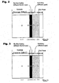
- FIG. 2 shows the sectional structure of the Ni-based alloy after the treatment. Further, Table 1 shows the analysis result of the composition of each point in FIG. 2 using an electron probe microanalyzer (EPMA). The data (1) to (5) in Table 1 correspond to the points (1) to (5) in FIG 2, respectively.
- EPMA electron probe microanalyzer
- the 45 atomic% Re-55 atomic% Cr alloy coating is formed as an alloy coating having an atomic composition of 38.1% Re, 48.2% Cr and 9.2% Ni. That is, the alloy coating has a composition of the ⁇ phase (see FIG 1).
- the other alloy element other than Re, Cr and Ni is less than 2% by atomic component, and has no significant function as a diffusion barrier.
- Ni-based alloy After an 40 atomic% Re-50 atomic% Cr-10 atomic% Ni alloy coating was coated on a Ni-based alloy of Inconel 738LC (Ni-16% Cr-8.5% Co-0.9% Nb-1.7% Mo-2.6%W-3.4 Ti-3.4% Al (weight %)) for use in a rotor blade or stationary blade of a gas turbine, the Ni-based alloy was Ni-plated, and then subjected to an Al diffusion coating.
- the alloy coating was formed by coating a 40 atomic% Re-50 atomic% Cr-10 atomic% Ni alloy on the surface of the substrate through a magnetron sputtering process using the Re-Cr alloy as a target, and then subjecting the substrate with the alloy layer to a homogenizing heat treatment in vacuum at 1100°C for 5 hours.
- a Watts bath was used for the Ni plating.
- the Al diffusion coating was performed under the condition that the substrate with coated Re alloy and plated-Ni was heated at 1000°C in vacuum for 5 hours while being immersed in a mixed powder of a Ni-50 atcimic% Al alloy powder and an Al 2 O 3 powder.
- FIG. 3 shows the sectional structure of the Ni-based alloy after the treatment. Further, Table 2 shows the analysis result of the composition of each point in FIG. 3 using an electron probe microanalyzer (EPMA).
- EPMA electron probe microanalyzer
- the 40 atomic% Re-50 atomic% Cr-10 atomic Ni alloy coating is formed as an alloy coating having an atomic composition of 24.2% Re, 39.5% Cr, and 31.8% Ni.
- This composition corresponds to a point slightly sifted from the stable region of the ⁇ phase toward high Ni side in the calculated phase diagram of FIG. 1.
- the other alloy element other than Re, Cr and Ni is less than 2% by atomic component, and has no significant function as a diffusion barrier.
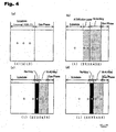
- FIGS. 4(a), 4(b), 4(c) and 4(d) show the sectional structures of a pure Ni-based alloy (Inconel 738LC) as Comparative Example 1, a Ni-based alloy (Inconel 738LC) subjected only to an Al diffusion coating as Comparative Example 2, a Ni-based alloy (Inconel 718) subjected to a Ni-plating and an Al diffusion coating after coating a 20 atomic% Re-60 atomic% Ni-20 atomic% Cr alloy coating thereon, as Comparative Example 3, and a Ni-based alloy (Inconel 738LC) subjected to a Ni-plating and an Al diffusion coating after coating a 20 atomic% Re-80 atomic% Cr alloy coating thereon, as Comparative Example 4, respectively.
- the Re alloy coating was formed by coating a 20 atomic% Re-60 atomic% Ni-20 atomic% Cr alloy in Comparative Example 3, or a 20 atomic% Re-80 atomic% Cr alloy in Comparative Example 4, on the substrate through a magnetron sputtering process, and subjecting the substrate with the alloy to a heat treatment at 1100°C in vacuum for 5 hours.
- the respective conditions of the Ni plating and the Al diffusion coating process were the same as those in Inventive example 1.
- Table 3 shows the analysis result of the composition of each point of the section of the Ni-based alloy in Comparative Example 1 according to EPMA.
- the data (1) to (3) in Table 3 correspond to the points (1) to (3) in FIG 4(a), respectively.
- Table 4 shows the analysis result of the composition of each point of the section of the Ni-based alloy in Comparative Example 2 according to EPMA.
- the data (1) to (5) in Table 4 correspond to the points (1) to (5) in FIG. 4(b), respectively.
- Table 5 shows the analysis result of the composition of each point of the section of the Ni-based alloy in Comparative Example 3 according to EPMA.
- the data (1) to (5) in Table 5 correspond to the points (1) to (5) in FIG 4(c), respectively.
- Table 6 shows the analysis result of the composition of each point of the section of the Ni-based alloy in Comparative Example 4.
- the data (1) to (5) in Table 6 correspond to the points (1) to (5) in FIG. 4(d), respectively. (atomic%) (1) (2) (3) (4) (5) Re 0.0 2.1 8.9 1.3 0.0 Ni 59.4 51.3 7.9 44.1 46.9 Cr 18.1 22.8 56.2 12.3 6.0 Co 8.2 7.1 3.9 2.7 2.2 W 0.8 0.7 0.5 0.2 0.0 Mo 1.2 0.9 0.9 0.3 0.0 Ta 0.5 0.4 0.2 0.1 0.0 Nb 0.6 0.4 0.3 0.2 0.1 Al 7.2 11.3 19.2 37.8 43.9 Ti 4.0 3.0 2.0 1.0 0.9
- the Al concentration in the vicinity of the surface of the coating layer composed of the Re alloy coating and the Ni-Al alloy diffusion layer is about 40 atomic%, which is a sufficient amount of Al to form Al 2 O 3 serving as a dense protective layer.
- Al and Ti/Nb are clearly diffused to the substrate and the coating layer, respectively.
- the 20 atomic% Re-60 atomic% Ni-20 atomic% Cr alloy coating is formed as an alloy coating having an atomic composition of 9.2% Re, 47.9% Ni, 19.4% Cr, 4.3% Co, 16.5% Al and 1.4% Ti. Leaving Al and Ti out of consideration, the composition corresponds to the Ni-rich region in FIG. 1, which is close to the composition of the alloy disclosed in the Japanese Patent Laid-Open Publication No. 11-61439 as one of the conventional examples.
- the 20 atomic% Re-80 atomic% Cr alloy coating is formed as an alloy coating having an atomic composition of 8.9% Re, 7.9% Ni, 56.2% Cr, 3.9% Co, 19.2% Al and 2.0% Ti. Leaving Al and Ti out of consideration, the composition corresponds to the Cr-rich phase in FIG 1, which is close to the composition of the alloy disclosed in the Japanese Patent Laid-Open Publication No. 2000-511236 as one of the conventional examples.
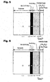
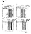
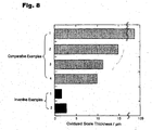
- FIGS. 5 and 6, and FIGS. 7(a) to 7(d) show the sectional structures of Inventive Examples 1 and 2, and Comparative Examples 1 to 4 after oxidized in the atmosphere at 1100°C for one month.
- FIGS. 2 and 3 correspond to FIGS. 5 and 6, respectively, and FIGS. 4(a) to 4(d) correspond to FIGS. 7(a) to 7(d), respectively.
- Table 7 shows the analysis result of the composition of each point of the section of an oxidized test piece of the Ni-based alloy in Inventive Example 1.
- the data (1) to (6) in Table 7 correspond to the points (1) to (6) in FIG 5, respectively. (atomic%) (1) (2) (3) (4) (5) (6) Re 0.0 0.0 52.5 0.0 0.0 0.0 Ni 60.1 58.0 1.8 48.0 50.2 0.0 Cr 18.4 21.5 42.1 1.9 0.4 0.0 Co 8.0 7.7 1.3 0.3 0.1 0.0 W 1.0 0.7 1.0 0.0 0.0 0.0 Mo 0.8 0.6 0.7 0.0 0.0 0.0 Ta 0.4 0.4 0.2 0.0 0.0 0.0 Nb 0.4 0.5 0.1 0.0 0.0 0.0 Al 7.0 0.3 49.8 49.3 39.8 Ti 3.9 3.6 0.0 0.0 0.0 0.0 O 0.0 0.0 0.0 0.0 0.0 60.2
- Table 8 shows the analysis result of the composition of each point of the section of an oxidized test piece of the Ni-based alloy in Inventive Example 2.
- the data (1) to (6) in Table 8 correspond to the points (1) to (6) in FIG 6, respectively.
- Table 9 shows the analysis result of the composition of each point of the section of an oxidized test piece of the Ni-based alloy in Comparative Example 1.
- the data (1) to (6) in Table 9 correspond to the points (1) to (6) in FIG 7(a), respectively.
- Table 10 shows the analysis result of the composition of each point of the section of an oxidized test piece of the Ni-based alloy in Comparative Example 2.
- the data (1) to (6) in Table 10 correspond to the points (1) to (6) in FIG. 7(b), respectively. (atomic%) (1) (2) (3) (4) (5) (6) Re 0.0 0.0 0.0 0.0 0.0 0.0 0.0 0.0 Ni 59.6 56.4 58.9 61.8 64.2 12.9 Cr 17.9 16.4 13.2 8.0 5.5 3.8 Co 8.0 8.5 6.6 5.1 3.7 7.2 Co 8.0 8.5 6.6 5.1 3.7 7.2 W 1.0 1.2 1.0 0.3 0.1 0.1 Mo 1.0 1.3 1.2 0.0 0.0 0.0 Ta 0.5 0.3 0.3 0.1 0.2 0.1 Nb 0.6 0.5 0.4 0.2 0.1 0.1 Al 7.3 12.9 16.3 23.9 25.7 23.6 Ti 4.1 2.5 2.1 0.6 0.5 0.7 O 0.0 0.0 0.0 0.0 0.0 51.5
- Table 11 shows the analysis result of the composition of each point of the section of an oxidized test piece of the Ni-based alloy in Comparative Example 3.
- the data (1) to (6) in Table 11 correspond to the points (1) to (6) in FIG 7(c), respectively.
- Table 12 shows the analysis result of the composition of each point of the section of an oxidized test piece of the Ni-based alloy in Comparative Example 4.
- the data (1) to (6) in Table 12 correspond to the points (1) to (6) in FIG 7(d), respectively.
- FIG 8 shows the thickness of each oxidized scale created these surfaces.
- Inventive Example 1 a dense oxidized scale with a thin thickness of about 2 ⁇ m containing Al 2 O 3 almost without other elements was formed on the surface of the coating layer, and no peeling of the film was observed.
- the diffusion of the elements (e.g. Ti and Nb) of the substrate to the Ni-Al alloy diffusion layer nor the diffusion of Al of the Ni-Al alloy diffusion layer to the substrate were practically observed.
- the concentration Al in the Ni-Al alloy diffusion layer was maintained at about 50% approximately equal to that before oxidation, and no significant change was observed in the composition of the substrate.
- the Re alloy diffusion barrier layer also exhibited substantially the same composition as that before oxidation.
- Inventive Example 2 a dense oxidized scale with a thin thickness of about 3 ⁇ m containing Al 2 O 3 almost without other elements was formed on the surface of the coating layer, and no peeling of the film was observed.
- the elements e.g. Ti and Nb
- the concentration Al in the Ni-Al alloy diffusion layer was maintained at about 50% approximately equal to that before oxidation, and no significant change was observed in the composition of the substrate.
- the Re alloy diffusion barrier layer also exhibited substantially the same composition as that before oxidation.
- the Al concentration of the Ni-Al diffusion layer was close to 50% before oxidation, it was reduced at about 27% after oxidation.
- the Al concentration in the vicinity of the surface of the substrate was also increased up to about 15%. Therefore, it can be proved that even if the 9.2% Re-47.9% Ni-19.4 Cr-4.3% Co-16.5% Al-1.4% Ti alloy coating having a low Re concentration is coated, Ti and Nb will be diffused from the substrate from the coating layer, and Al will be diffused from the Ni-Al diffusion layer to the substrate, during oxidation at 1100°C.
- the diffusion-barrier ReCrNi alloy coating consisting essentially of a ternary alloy and, having, except for inevitable impurities, an atomic composition of 20 % to 80 % Re, an atomic composition of 20 % to 600 % Cr, and an atomic composition of 5 % to 40 % Ni can be coated on the surface of a high-temperature equipment member (or inserted between the substrate and the TBC layer) to provide excellent heat/corrosion resistances, and an extended life span as compared to conventional techniques.
Landscapes
- Chemical & Material Sciences (AREA)
- Inorganic Chemistry (AREA)
- Chemical Kinetics & Catalysis (AREA)
- Engineering & Computer Science (AREA)
- Materials Engineering (AREA)
- Mechanical Engineering (AREA)
- Metallurgy (AREA)
- Organic Chemistry (AREA)
- Other Surface Treatments For Metallic Materials (AREA)
- Turbine Rotor Nozzle Sealing (AREA)
Applications Claiming Priority (3)
| Application Number | Priority Date | Filing Date | Title |
|---|---|---|---|
| JP2001335915 | 2001-10-31 | ||
| JP2001335915 | 2001-10-31 | ||
| PCT/JP2002/009478 WO2003038151A1 (fr) | 2001-10-31 | 2002-09-13 | Revetement en alliage recrni pour barriere de diffusion |
Publications (2)
| Publication Number | Publication Date |
|---|---|
| EP1457584A1 true EP1457584A1 (fr) | 2004-09-15 |
| EP1457584A4 EP1457584A4 (fr) | 2004-11-24 |
Family
ID=19150838
Family Applications (1)
| Application Number | Title | Priority Date | Filing Date |
|---|---|---|---|
| EP02765560A Withdrawn EP1457584A4 (fr) | 2001-10-31 | 2002-09-13 | Revetement en alliage recrni pour barriere de diffusion |
Country Status (4)
| Country | Link |
|---|---|
| US (1) | US7192655B2 (fr) |
| EP (1) | EP1457584A4 (fr) |
| JP (1) | JP3857689B2 (fr) |
| WO (1) | WO2003038151A1 (fr) |
Cited By (1)
| Publication number | Priority date | Publication date | Assignee | Title |
|---|---|---|---|---|
| CN101914774A (zh) * | 2010-08-19 | 2010-12-15 | 上海应用技术学院 | 具有Re-Ni-Cr合金扩散障碍层的粘结层材料及其制备方法 |
Families Citing this family (7)
| Publication number | Priority date | Publication date | Assignee | Title |
|---|---|---|---|---|
| US20050110142A1 (en) * | 2003-11-26 | 2005-05-26 | Lane Michael W. | Diffusion barriers formed by low temperature deposition |
| US8133595B2 (en) | 2006-11-16 | 2012-03-13 | National University Corporation Hokkaido University | Multilayer alloy coating film, heat-resistant metal member having the same, and method for producing multilayer alloy coating film |
| JP4896702B2 (ja) * | 2006-12-22 | 2012-03-14 | 株式会社ディ・ビー・シー・システム研究所 | 合金皮膜、合金皮膜の製造方法および耐熱性金属部材 |
| RU2008111820A (ru) | 2007-03-29 | 2009-10-10 | Ибара Корпорейшн (JP) | Электролит для нанесения гальванических покрытий методом химического восстановления и способ получения элемента высокотемпературного устройства с применением такого электролита |
| JP5794537B2 (ja) * | 2012-05-11 | 2015-10-14 | 株式会社ディ・ビー・シー・システム研究所 | 耐熱合金部材およびその製造方法ならびに合金皮膜およびその製造方法 |
| WO2018039198A1 (fr) * | 2016-08-22 | 2018-03-01 | Gvm, Inc. | Équilibrage pour essieu réglable |
| CN116103617A (zh) * | 2022-12-30 | 2023-05-12 | 中国科学院金属研究所 | 一种含有ReCr基扩散障的MCrAlY涂层及其制备方法 |
Citations (4)
| Publication number | Priority date | Publication date | Assignee | Title |
|---|---|---|---|---|
| US5154885A (en) * | 1989-08-10 | 1992-10-13 | Siemens Aktiengesellschaft | Highly corrosion and/or oxidation-resistant protective coating containing rhenium |
| JPH0813069A (ja) * | 1994-07-05 | 1996-01-16 | Hitachi Ltd | 耐熱構造材用Ni基合金及びそれを用いたガスタービン |
| JPH1161439A (ja) * | 1997-08-15 | 1999-03-05 | Mitsubishi Heavy Ind Ltd | ガスタービン翼への耐食性表面処理方法及びその動・静翼 |
| EP0921209A2 (fr) * | 1997-11-26 | 1999-06-09 | Rolls-Royce Plc | Pièce en superalliage revêtue et méthode pour appliquer un revêtement sur un article en superalliage |
Family Cites Families (5)
| Publication number | Priority date | Publication date | Assignee | Title |
|---|---|---|---|---|
| JPS60243242A (ja) * | 1984-05-16 | 1985-12-03 | Pilot Pen Co Ltd:The | 耐摩耗性Re合金の焼結体およびその製造方法 |
| DE59505454D1 (de) * | 1994-10-14 | 1999-04-29 | Siemens Ag | Schutzschicht zum schutz eines bauteils gegen korrosion, oxidation und thermische überbeanspruchung sowie verfahren zu ihrer herstellung |
| JPH09143667A (ja) | 1995-11-21 | 1997-06-03 | Mitsubishi Heavy Ind Ltd | Re製高温部材の製造方法 |
| DE19621763A1 (de) | 1996-05-30 | 1997-12-04 | Siemens Ag | Erzeugnis mit einem Grundkörper aus einer Superlegierung und einem darauf befindlichen Schichtsystem sowie Verfahren zu seiner Herstellung |
| US6746782B2 (en) * | 2001-06-11 | 2004-06-08 | General Electric Company | Diffusion barrier coatings, and related articles and processes |
-
2002
- 2002-09-13 JP JP2003540412A patent/JP3857689B2/ja not_active Expired - Fee Related
- 2002-09-13 EP EP02765560A patent/EP1457584A4/fr not_active Withdrawn
- 2002-09-13 WO PCT/JP2002/009478 patent/WO2003038151A1/fr active Application Filing
- 2002-09-13 US US10/494,022 patent/US7192655B2/en not_active Expired - Fee Related
Patent Citations (4)
| Publication number | Priority date | Publication date | Assignee | Title |
|---|---|---|---|---|
| US5154885A (en) * | 1989-08-10 | 1992-10-13 | Siemens Aktiengesellschaft | Highly corrosion and/or oxidation-resistant protective coating containing rhenium |
| JPH0813069A (ja) * | 1994-07-05 | 1996-01-16 | Hitachi Ltd | 耐熱構造材用Ni基合金及びそれを用いたガスタービン |
| JPH1161439A (ja) * | 1997-08-15 | 1999-03-05 | Mitsubishi Heavy Ind Ltd | ガスタービン翼への耐食性表面処理方法及びその動・静翼 |
| EP0921209A2 (fr) * | 1997-11-26 | 1999-06-09 | Rolls-Royce Plc | Pièce en superalliage revêtue et méthode pour appliquer un revêtement sur un article en superalliage |
Non-Patent Citations (3)
| Title |
|---|
| PATENT ABSTRACTS OF JAPAN vol. 1996, no. 05, 31 May 1996 (1996-05-31) -& JP 08 013069 A (HITACHI LTD), 16 January 1996 (1996-01-16) * |
| PATENT ABSTRACTS OF JAPAN vol. 1999, no. 08, 30 June 1999 (1999-06-30) -& JP 11 061439 A (MITSUBISHI HEAVY IND LTD), 5 March 1999 (1999-03-05) * |
| See also references of WO03038151A1 * |
Cited By (2)
| Publication number | Priority date | Publication date | Assignee | Title |
|---|---|---|---|---|
| CN101914774A (zh) * | 2010-08-19 | 2010-12-15 | 上海应用技术学院 | 具有Re-Ni-Cr合金扩散障碍层的粘结层材料及其制备方法 |
| CN101914774B (zh) * | 2010-08-19 | 2012-07-25 | 上海应用技术学院 | 具有Re-Ni-Cr合金扩散障碍层的粘结层材料的制备方法 |
Also Published As
| Publication number | Publication date |
|---|---|
| EP1457584A4 (fr) | 2004-11-24 |
| US20050037222A1 (en) | 2005-02-17 |
| JPWO2003038151A1 (ja) | 2005-02-24 |
| US7192655B2 (en) | 2007-03-20 |
| WO2003038151A1 (fr) | 2003-05-08 |
| JP3857689B2 (ja) | 2006-12-13 |
Similar Documents
| Publication | Publication Date | Title |
|---|---|---|
| EP2083097B1 (fr) | Film de revêtement en alliage multicouche, élément métallique résistant à la chaleur muni de ce film de revêtement et procédé de fabrication d'un film de revêtement en alliage multicouche | |
| EP1652959B1 (fr) | Procédé de fabrication des revêtements d'aluminide de nickel de phase gamma prime | |
| EP1806433A2 (fr) | Couche de diffusion et procédé de fabrication | |
| EP2193225B1 (fr) | Couche de liaison bimétallique pour un revêtement barrière thermique sur un superalliage | |
| JP4753720B2 (ja) | 拡散バリヤ用合金皮膜及びその製造方法、並びに高温装置部材 | |
| EP1254967A1 (fr) | Système amélioré de revêtement de barrière thermique de projection par plasma | |
| EP1522608A2 (fr) | Revêtement formant barrière de diffusion pour composant de moteur à turbine et méthode de formation | |
| EP0979881A1 (fr) | Systeme de revêtement a barrière thermique comportant un revêtement de liaison à base d'un composite d'un métal et un oxyde de métal | |
| EP1132499A2 (fr) | Revêtement d'alliage, procédé de sa fabrication, et élément pour des appareils haute température | |
| EP2697408B1 (fr) | Couche d'arrêt de diffusion contenant de l'iridium sur un article métallique | |
| US20090317658A1 (en) | Alloy coating film, method for production of alloy coating film, and heat-resistant metal member | |
| EP2690197B1 (fr) | Aube de turbine pour turbine à gaz industrielle et turbine à gaz industrielle | |
| US20100330295A1 (en) | Method for providing ductile environmental coating having fatigue and corrosion resistance | |
| JP2013127117A (ja) | ニッケル−コバルト基合金及びボンドコート並びに該合金を含むボンドコート物品 | |
| US7138189B2 (en) | Heat-resistant Ti alloy material excellent in resistance to corrosion at high temperature and to oxidation | |
| US7205053B2 (en) | Re alloy coating for diffusion barrier | |
| US7192655B2 (en) | ReCrNi alloy coating for diffusion barrier | |
| JP3708909B2 (ja) | レニウム含有合金皮膜を被着してなる耐高温酸化性耐熱合金部材の製造方法 | |
| US7060368B2 (en) | ReCr alloy coating for diffusion barrier | |
| US20100330393A1 (en) | Ductile environmental coating and coated article having fatigue and corrosion resistance |
Legal Events
| Date | Code | Title | Description |
|---|---|---|---|
| PUAI | Public reference made under article 153(3) epc to a published international application that has entered the european phase |
Free format text: ORIGINAL CODE: 0009012 |
|
| 17P | Request for examination filed |
Effective date: 20040428 |
|
| AK | Designated contracting states |
Kind code of ref document: A1 Designated state(s): AT BE BG CH CY CZ DE DK EE ES FI FR GB GR IE IT LI LU MC NL PT SE SK TR |
|
| AX | Request for extension of the european patent |
Extension state: AL LT LV MK RO SI |
|
| A4 | Supplementary search report drawn up and despatched |
Effective date: 20041012 |
|
| RAP1 | Party data changed (applicant data changed or rights of an application transferred) |
Owner name: EBARA CORPORATION Owner name: NARITA, TOSHIO |
|
| 17Q | First examination report despatched |
Effective date: 20100608 |
|
| STAA | Information on the status of an ep patent application or granted ep patent |
Free format text: STATUS: THE APPLICATION IS DEEMED TO BE WITHDRAWN |
|
| 18D | Application deemed to be withdrawn |
Effective date: 20101019 |