EP1457330A2 - Unabhängiger Antrieb des zweiten Falzmesserzylinders - Google Patents
Unabhängiger Antrieb des zweiten Falzmesserzylinders Download PDFInfo
- Publication number
- EP1457330A2 EP1457330A2 EP04102165A EP04102165A EP1457330A2 EP 1457330 A2 EP1457330 A2 EP 1457330A2 EP 04102165 A EP04102165 A EP 04102165A EP 04102165 A EP04102165 A EP 04102165A EP 1457330 A2 EP1457330 A2 EP 1457330A2
- Authority
- EP
- European Patent Office
- Prior art keywords
- folding
- cylinder
- folding knife
- jaw
- folder
- Prior art date
- Legal status (The legal status is an assumption and is not a legal conclusion. Google has not performed a legal analysis and makes no representation as to the accuracy of the status listed.)
- Granted
Links
Images


Classifications
-
- B—PERFORMING OPERATIONS; TRANSPORTING
- B65—CONVEYING; PACKING; STORING; HANDLING THIN OR FILAMENTARY MATERIAL
- B65H—HANDLING THIN OR FILAMENTARY MATERIAL, e.g. SHEETS, WEBS, CABLES
- B65H45/00—Folding thin material
- B65H45/12—Folding articles or webs with application of pressure to define or form crease lines
- B65H45/28—Folding in combination with cutting
-
- B—PERFORMING OPERATIONS; TRANSPORTING
- B65—CONVEYING; PACKING; STORING; HANDLING THIN OR FILAMENTARY MATERIAL
- B65H—HANDLING THIN OR FILAMENTARY MATERIAL, e.g. SHEETS, WEBS, CABLES
- B65H45/00—Folding thin material
- B65H45/12—Folding articles or webs with application of pressure to define or form crease lines
- B65H45/16—Rotary folders
- B65H45/162—Rotary folders with folding jaw cylinders
-
- B—PERFORMING OPERATIONS; TRANSPORTING
- B41—PRINTING; LINING MACHINES; TYPEWRITERS; STAMPS
- B41P—INDEXING SCHEME RELATING TO PRINTING, LINING MACHINES, TYPEWRITERS, AND TO STAMPS
- B41P2213/00—Arrangements for actuating or driving printing presses; Auxiliary devices or processes
- B41P2213/70—Driving devices associated with particular installations or situations
- B41P2213/73—Driving devices for multicolour presses
- B41P2213/734—Driving devices for multicolour presses each printing unit being driven by its own electric motor, i.e. electric shaft
-
- B—PERFORMING OPERATIONS; TRANSPORTING
- B65—CONVEYING; PACKING; STORING; HANDLING THIN OR FILAMENTARY MATERIAL
- B65H—HANDLING THIN OR FILAMENTARY MATERIAL, e.g. SHEETS, WEBS, CABLES
- B65H2404/00—Parts for transporting or guiding the handled material
- B65H2404/40—Shafts, cylinders, drums, spindles
- B65H2404/42—Arrangement of pairs of drums
- B65H2404/421—Bed arrangement, i.e. involving parallel and spaced drums, e.g. arranged horizontally for supporting a roll to be wound or unwound
- B65H2404/4211—Bed arrangement, i.e. involving parallel and spaced drums, e.g. arranged horizontally for supporting a roll to be wound or unwound with means for changing space between the drums
-
- B—PERFORMING OPERATIONS; TRANSPORTING
- B65—CONVEYING; PACKING; STORING; HANDLING THIN OR FILAMENTARY MATERIAL
- B65H—HANDLING THIN OR FILAMENTARY MATERIAL, e.g. SHEETS, WEBS, CABLES
- B65H2601/00—Problem to be solved or advantage achieved
- B65H2601/10—Ensuring correct operation
- B65H2601/11—Clearing faulty handling, e.g. jams
Definitions
- the invention relates to a folder of a rotary printing press according to the Preamble of claim 1.
- DE 36 36 244 C2 discloses a folder with a pivotable stapling cylinder, which optionally interacts with a first or second jaw cylinder.
- DE 44 07 375 A1 discloses a folder with at least one Jaw cylinder and one in a working position with the jaw cylinder interacting first folding knife cylinder and a second folding knife cylinder, the second folding knife cylinder from the working position to a rest position is movable.
- EP 0 729 910 A2 and DE 42 08 353 A1 have folders with one Folding jaw cylinder and a first and second folding knife cylinder are known, wherein the first folding knife cylinder and the folding jaw cylinder together by one Electric motor are driven.
- the invention has for its object to provide a folder.
- displaceable folding cylinder is mounted between two side parts that counter Side frames of the folder are pivoted, a modular design of the Folders enabled.
- the use of a dedicated motor for Driving the displaceable folding cylinder enables decoupling from it Movement of vibrations in the folder by variably loaded others rotating parts such as a cutting or puncturing roller.
- Another advantage of using the dedicated motor is that, different than with a common drive of the folding cylinder and folding jaw cylinder Tooth mesh, by appropriate control of this motor, the phase position of the Folding cylinder relative to the jaw cylinder cooperating with it is easy to change.
- a coupling of the rotation of the Motor to the width of the jaw gap are provided so that a Folding knife of the folding cylinder in the middle of each width of the folding jaw gap intervenes. This makes the folder very easy and quick to process Customizable signatures of different thicknesses.
- Another advantage is that there is no second cross fold d. has a significant influence on the design of the basic unit of the folder. H., that the usual bearing holes and the oil space required for the gear drive are eliminated and do not require an increase in the frames of the folder.
- the folder also has a stationary stored folding cylinder.
- the stationary folding cylinder can then be used for production serve a first cross fold on the product, whereas the displaceable folding cylinder can be used to produce a second cross fold.
- B Usually a large part of the circulation of daily newspapers, which is to be published in Subscription or for street sale, made with a simple cross fold for the part of the edition that is intended for mailing second cross fold needed to get the newspaper to a usable for mailing To bring format.
- the folder according to the invention allows the production of Newspaper with or without a second cross fold, whereby for the support part without a second cross fold the displaceable folding cylinder is pivoted into the rest position and its drive at running folder can be switched off.
- the Folding jaw cylinder has pairs of folding jaws, the second folding jaw one Couple each cooperates with a different folding cylinder.
- the finished folded product can therefore immediately are transferred from the jaw cylinder to a belt guidance system or the like, and product promotion is simplified.
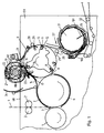
- Fig. 1 shows a schematic section of a folder one Rotary printing press.
- One in the folder from one (not shown) Folding former coming in web 1 or one of several webs existing strand first passes through a pair of draw rollers 2 and reaches then a gap 3 between a cutting cylinder 4 and a stationary stored first folding knife cylinder 7.
- the cutting cylinder 4 carries on its circumference Knives which cooperate with knife grooves of the first folding knife cylinder 7 and which Cut web 1 into individual signatures.
- the individual signatures are from a Holding device of the first folding knife cylinder 7 such as a gripper or Puncture needles are captured and the signature is thus counterclockwise between the figure the first folding knife cylinder 7 and the lower region of the first Folding knife cylinder 7 guided first guide plate 6.
- the first baffle 6 ends near a gap 8 between the first Folding knife cylinder 7 and a folding jaw cylinder 9.
- This folding jaw cylinder 9 has on its circumference a number of first jaws 11, which are in the circumferential direction are evenly spaced from each other.
- the Folding jaw cylinder 9 three first folding jaws 11 at an angular distance of 120 °.
- the Removal of two first jaws 11, measured on the circumference of the Folding jaw cylinder 9, corresponds to the length of an unfolded signature
- the first Folding jaws 11 each have a strip-like, fixed to the folding jaw cylinder 9 Jaws 12 and one coupled with the rotary movement of the jaw cylinder 9 pivotable jaws 13.
- a second baffle 14 closes the opening gap of the second gap 8. It serves for this purpose, the one released by the holding device of the first folding knife cylinder 7 fold over the front half of the signature so that the signature is folded in front of the jaw cylinder 9 is further promoted.
- 1 shows a signature with 16 referred to at this stage of processing, the former leading part 17 of the Signature 16 strokes along the second guide plate 14.
- a second guide plate or pressure element 18 connects to the second guide plate 14 Structure is shown in more detail in Fig. 5 and will be described later.
- This guide or pressure element 18 is in the reception gusset of a third Gap 10 that between the jaw cylinder 9 and a second Folding knife cylinder 19 is defined.
- This second folding knife cylinder 19 carries on his Two diametrically opposed holding devices, here in the form of grippers 21. Since the number of grippers 21 or folding blades 22 is smaller than that of the first Folding jaws 11, is also the diameter of the second folding blade cylinder 19 in Ratio smaller than that of the jaw cylinder 9. This facilitates the arrangement of the two folding knife cylinders 7; 19 and one described later Belt guide system 27 on the circumference of the jaw cylinder 9.
- the second folding knife cylinder 19 also carries two Folding knife 22.
- the distance between the gripper 21 and the following folding knife 22 the second folding knife cylinder 19 is adjustable and is expediently set to one Quarter of the length of the signature 16 set to a second with the folding knife 22 Cross fold in the signature 16, which has already been folded once, in the middle.
- This second folding knife cylinder 19 can have several in its circumference Have spaced holding devices, here in the form of grippers 21 and with the number 2. In the same way as that of the holding devices are also Folding knife placed, according to the format length equally far from the Holding devices removed. The smaller the number of holding devices or Folding knife, the smaller the design of the second folding knife cylinder can be become. In the smallest case, a holding device and 1 folding knife can also be present his.
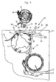
- the phase of the generation of the second transverse fold is shown in FIG. 2 on the basis of a partial section of the folder.
- the first transverse fold of the signature 16 is through the gripper 21 is lifted from the surface of the jaw cylinder 9; the first Folding flap 11 is empty and open.
- a second jaw 23 is on the circumference of the Folding jaw cylinder 9 arranged at a distance from the first folding jaw 11, the the distance between the gripper 21 and the folding knife 22 on the second folding knife cylinder 19 equivalent.
- the distance between the first and second folding jaws 11 and 23 is also adjustable.
- the folding knife 22 presses the signature 16 into the open gap of the folding flap 23 and Signature 16 is clamped in the gap. At the same time, the gripper 21 gives the first Cross fold of signature 16 free.
- Guide brushes 24 are in the exit gusset of the gap between the second folding knife cylinder 19 and jaw cylinder 9 arranged. As can be seen in FIG. 3, they serve to the two legs of the signature 16, now folded twice, against the surface of the To pivot jaw cylinder 9 and thus to complete the folding process Passage through the gap between the guide brushes 24 and the jaw cylinder 9 finished folded product 26 can be seen in Fig. 2
- Belts 29 accept the product 26, which is approximately in its position shown in FIG. 2 is released by the second jaw 23 and feeds it to a paddle wheel 31, which flakes the product 26 in a conventional manner on a belt delivery 32 deposits, the guide tongues 100 at a distance from the stop 101 are pivoted, which corresponds approximately to the length of the product 26.
- the second folding knife cylinder 19 forms together with the guide or pressure element 18 and the guide brushes 24 are a modular unit, which is shown in FIGS. 1 to 3
- Working position of the second folding knife cylinder 19 in an idle position is shiftable, which is shown in Fig. 4.
- In this idle position is the second Folding knife cylinder 19 against an angle of approximately 105 ° about an axis 33
- Work position pivoted, instead a third baffle 34 on the Folding jaw cylinder 9 swung open and thus forms a continuous guide gap 36 for the signature 16, which is essentially without interruption from the second Baffle 14 to a guide body 37 and further to the first roller 28 of the Belt control system 27 extends.
- the third baffle 34 prevents the freshly folded signature 16 itself on its way from the end of the second baffle 14 to unfolded to the tip of the guide body 37 when the second folding knife cylinder 19 is inactive.
- the guide tongues 100 are at a distance from each other the stop 101 pivoted, which corresponds approximately to the length of the product 26.
- the second Folding knife cylinder 19 and guide brushes 24 formed unit between production with single and double cross fold can be switched. Because the second Folding knife cylinder 19 in production with a simple cross fold no transport function has more, its drive can be switched off in the idle position, even if the folder is working.
- Fig. 5 shows in detail the structure of the guide or pressure element 18. It comprises one Carrier 38, which is fixedly connected to a (not shown) side part (74, see Fig. 7) that is at the same time a holder for the axis 33 of the second folding knife cylinder 19th forms and carries the guide brushes 24.
- a pivot arm 39 hinged to the carrier 38 carries a rotatable roller 41 at one end and two bores for at the other end a screw 42 and a set screw 43.
- the set screw 43 is axially adjustable and has a tip 44 opposite the carrier 38. This tip 44 forms one Stop that pivots the roller 41 counterclockwise in FIG. 5 limited.
- the screw 42 extends through a bore of the carrier 38 and carries at its distal end two knurled nuts 46; 47, of which a knurled nut 46 for Adjust the pivoting freedom of movement of the roller 41 and the other knurled nut 47 serves to counter the first knurled nut 46.
- a spring 48 e.g. B. a coil spring 48 exerts a clockwise torque on the swivel arm 39.
- the setting of the threaded pin 43 specifies the maximum distance by which the Roller 41 when a signature 16 passes between it and the jaw cylinder 9 can remove from the latter by pivoting the swivel arm 39.
- This maximum The distance is expediently set to a value with slight play corresponds to the expected thickness of the signature 16, which is simply folded transversely. If in the case of a paper stopper the thickness of the signature 16 is greater, and the roller 41 over that of the set screw 43 predetermined amount is pushed up, the entire assembly pivoted upwards from the working position, and one Damage to the sensitive moving parts of jaw cylinder 9 and second folding knife cylinder 19 is avoided.
- a servo mechanism can also be provided that removes the roll 41 measures the force transmitted to the carrier 38 and when a limit value is exceeded an actuator drives to the second folder cylinder 19 from its working position swing out.
- the on and off can also be done via the electric motor 73, which acts on the axis 33 Swiveling the folding knife cylinder 19 causes and with an electric Standstill moment against the gas pressure spring 75 the folding knife cylinder 19 in Holds down working position, due to torque limitation in the event of overloading one Paper jam will trigger the swivel.
- the gas pressure spring 75 takes over the function of the Take off to keep a safe distance between them even at the time of coasting To reach jaw cylinder 9 and folder cylinder 19, the gripper 21 and Folding knife 22 protects. Until the time of coasting, the synchronous Braking is fed from the DC link via the voltage that is still present.
- a second task of the guiding or pressing element 18 is a low-friction guidance to ensure the signature 16.
- the roller 41 exercises due to its rotatability much less friction on a continuous signature 16 than with one immovable baffle as the baffle 14 would be the case. Therefore work at the moment the transfer of the first transverse fold to the gripper 21 of the second folding knife cylinder 19 at most low braking friction forces on the signature 16, what the handover simplified and their accuracy improved
- Fig. 6 shows a schematic Section of a structure of a rotatable suspension through which such adjustment is controllable.
- the construction is here with reference to the jaw cylinder 9 described, but is transferable to the second folding knife cylinder 19.
- the Suspension includes a flange 50 on one of its end faces, here the inner one End face 49 is attached to a side frame 51 of the folder.
- a cylindrical one Extension 52 engages through an opening in the side frame 51 into the interior of the folder on;
- a spindle 53 is guided in an axial bore of the extension 52.
- the spindle 53 carries a thread 54 at its end pointing inside the folder, on which a nut 56 rides an anti-rotation pin 57 rigidly connected to the nut 56 engages in a blind hole 58 of the extension 52.
- the nut 56 is thereby non-rotatable held, but is back and forth by rotating the spindle 53 in the axial direction displaceable.
- the mother 56 carries on its outer circumference a bearing 59, for. B. a deep groove ball bearing 59. Via the deep groove ball bearing 59, axial adjusting forces from the nut 56 are rotatable Adjusting drum 61; 77 transferable.
- the adjusting drum 61; 77 is also about an axial sliding bearing 62, such as a needle bearing, on the outer periphery of the extension 52 supported.
- the adjusting drum 61; 77 has two on its outer circumference Helical gears 63; 64; 82; 83 with different helix angles.
- the two helical gears 63; 64; 82; 83 engage in two sprockets 66; 67; 84; 86 a, of which a ring gear 67; 86 the outer surface of the jaw cylinder 9 and the carries first jaws 11 firmly connected to the lateral surface; the other ring gear 66; 84 is connected to the adjustable second folding jaws 23.
- a rotation of the spindle 53 causes an axial displacement of the adjusting drum 61; 77 and so that depending on the helix angle of the helical gears 63; 64, 82; 83 different rotation of the two ring gears 66, 67; 84; 86 relative to each other.
- the twist stroke depends on the difference in the helix angle as well Diameter of the jaw cylinder 9 from. A stroke of a few centimeters on the circumference of the jaw cylinder 9 is for most practical applications completely sufficient.
- An adjustable stop 78 is located at two points away from the axis 33 Side frame 51 attached. During the contact of the side part 74 with the stop 78 activated the working position of the second folding blade cylinder 19, the contact of the Side part 74 with the stop 80 the rest position of the second folding knife cylinder 19th out.
- the position of the second folding knife cylinder 19 is relative to the jaw cylinder 9 in the working position regardless of the accuracy of the Electric motor 73 or the reduction gear adjustable.
- the stops 78 and 80 also include an initiator or switch that is in contact with the side part 74 on the electric motor 73 triggers a stop and other drive motors on Releases the folder to run, including the second electric motor 76.
- the electric motor 73 exercises in the working position of the second folding knife cylinder 19 over a predetermined standstill moment a pressure on the stop 78 and on the gas pressure spring 75, which is thus pressed and a Represents opposing force. Then, due to a paper jam, the pressure between the both cylinders 9 and 19 are too large and there is a risk of machine damage, If the standstill torque on the electric motor 73 is overcome, the electric motor 73 enters Action and lifts the second over the gearbox and with the help of gas pressure spring 75 Folding knife cylinder 19 from the work area upwards. All motors on the folder including the second electric motor 76 are stopped.
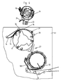
- Fig. 7 shows a schematic side view of part of the folder.
- the cutting cylinder 4 Between the side frame 51 and an opposite side frame, not shown, are the cutting cylinder 4, the first folder cylinder 7, the jaw cylinder 9, the belt guide system 27 and the paddle wheel 31 is arranged.
- the scope of the in Fig. 7 itself from that Side frame 51 concealed jaw cylinder 9 is by a dashed line 71 indicated.
- a housing 72 with an electric motor 73 is mounted on the upper edge 68.
- the housing 72 contains e.g. B. a reduction gear for transmitting the Driving force of the electric motor 73 on the axis 33, around which, as already explained, the second folding knife cylinder 19 from its working position to the idle position is pivotable.
- the second folding knife cylinder 19 is between two side parts 74 rotatably mounted, one of which can be seen in the Fig., The side part is in the working position by a solid outline and in the idle position represented by a dashed outline; the axis 33 is with both side parts 74 firmly connected.
- On the side of the side part 74 facing away from the viewer is a through a dashed outline indicated second electric motor 76 mounted by a Pinion 81, via a control drum 61, also indicated by dashed lines; 77 the second Folding knife cylinder 19 drives.
- Between the two side parts 74 are also Guide or pressure element 18 and the guide brushes 24 mounted.
- the elements 74, 76, 77, 78, 18, 19 and 24 mentioned form together with the Housing 72 and the electric motor 73 an independent module that when not in use can be removed from the folder
- This modular construction enables it also to build simple and inexpensive folders that lack the module, but which are equipped for the subsequent installation of such a module. This enables a print shop to reduce the investment for a folder hold as long as there is no need for double cross fold products; If If the need arises, the folder can be purchased by purchasing the module at a lower cost and simple and space-saving way for the production with double cross fold be made fit.
- a control circuit (not shown) controls the rotational movement of the second Electric motor 76 and thus that of the second folding knife cylinder 19 exactly in sync with Rotary movement of the jaw cylinder 9. It regulates the relative phase position of the Folding jaw cylinder 9 and the second folding blade cylinder 19 taking into account the one set on the second folding flaps 23 for receiving the signature 16 Gap width, so that it is ensured that a folding knife 22 of the second Folding knife cylinder 19 always meets in the center in an assigned folding jaw gap.
- FIG. 8 shows the drive of the second folding knife cylinder 19 in a highly schematic manner second electric motor 76 drives a pinion 81 via a clutch 79, which is used for shielding of the second electric motor 76 against irregularities in the rotational movement of the subordinate gear serves.
- This gearbox includes the pinion 81 already mentioned with reference to FIG. 7, actuated by this actuating drum 61; 77. How can be seen in Fig. 8, this adjusting drum 61; 77 two helical gears 63; 64; 82; 83, of which only one helical toothing 82 meshes with the pinion 81.
- the Structure of the adjusting drum 61; 77 corresponds to that described with reference to FIG.
- the toothing 82; 83 are helical gears with different Helix angle as the helical teeth 63; 64, and they are through one with help a rotating spindle driven mechanism axially displaceable.
- axial Displacement is an angular offset between two of the helical gears 82, 83 driven gears 84; 86 adjustable.
- the gear 84 drives via a hollow shaft 87 and two arms 88 which can be seen more precisely in FIG Direction connected to each other, the rotational movement of the folding knife 22 on; the Gear 86 drives the shaft 89 through a shaft 89 which is guided through the hollow shaft Rotation of the jacket of the second folding knife cylinder 19 and the gripper 21.
- the figure also schematically shows swivel arms 69, each with one of the Folding knife 22 or gripper 21 are connected and fixed to one of the side parts 74 unroll connected cam 70 and so each to the rotational position of the second folding knife cylinder 19 coupled opening and closing movement of the gripper Ensure 21 or pivoting movement of the folding knife 21.
- each coupled electric motors can be provided are, whereby the coupling ensures that the distances between the first and second jaws 11; 23 on the one hand and between grippers 21 and Folding knives 22, on the other hand, are always varied to the same extent.
- FIG. 9 shows a further development of the folder in a partial Section analogous to that of FIG. 4. Components that are already with reference to FIGS. 1 to 8 have been described, have the same reference numerals here and are not described again.
- the second folding knife cylinder 19 is located in FIG Idle position in which a wider between him and the jaw cylinder 9 Interspace 95 lies.
- a belt guide system 91 has two movable rollers 92; 93 on, which, when the second folding blade cylinder 19 is in the working position, in an inactive position (not shown) behind the guide brushes 24, and the are coupled to the position of the second folding knife cylinder 19 such that they are at Swiveling the second folding knife cylinder 19 against its idle position the transport direction of the signature 16 on the jaw cylinder 9 into that in FIG. 9 Advance positions shown in the direction of arrow 94.
- Another role 96 of the Belt guide system 91 is transverse to the general orientation of the Belt guide system 91 in the direction of arrow 97 against a spring force displaceable to by the rollers 92; 93 guided band 98 regardless of position the rollers 92; 93 to keep it taut.
- the belt guide system 91 touches this belt 98 on the circumference of the jaw cylinder 9 on that part of its circumference where the first jaws 11 open to the to release signature 16 promoted from the inside.
- the guide body 37 is pivotable suspended and touches the surface of the Folding jaw cylinder 9.
- the signature 16 released by the first folding jaw 11 becomes so lifted by the guide body 37 from the jaw cylinder 9 and between the guide body 37 and the belt 98 further promoted.
- To one in the direction of transport rear end of the guide body 37 closes a second band 99 of the Tape guide system 91. Between the two bands 98; 99 becomes the signature 16 for input of a folding device (not shown) for producing a second one Longitudinal fold promoted.
- the design of FIG. 9 thus allows, depending on Position of the second folding knife cylinder 19, the generation of a second cross fold or a second longitudinal fold on the product 26.
- a development not shown in a separate figure includes both pivotable third guide plate 34 from FIG. 4 as well as the belt guide system 91 from FIG. 9.
- This coupling causes that when the second Folding knife cylinder 19 is in its idle position, either the baffle 34 can be folded against the jaw cylinder 9, as shown in Fig. 4, or that Belt guide system 91 engages in the space 95.
Abstract
Description
- Fig. 1
- einen schematischen Schnitt durch einen Falzapparat gemäß der Erfindung in einer ersten Phase des Falzvorgangs;
- Fig. 2
- einen partiellen Schnitt entsprechend dem aus Fig. 1 in einer zweiten Phase des Falzvorgangs;
- Fig. 3
- einen Teilschnitt entspricht Fig. 2 in einer dritten Phase des Falzvorgangs;
- Fig. 4
- einen Teilabschnitt des Falzapparats mit in eine Untätigkeitsstellung verlagertem Falzzylinder;
- Fig. 5
- ein Leit- oder Andrückelement;
- Fig. 6
- eine Greiferregulierung bzw. Falzklappenregulierung im axialen Schnitt;
- Fig. 7
- eine partielle Seitenansicht des Falzapparats;
- Fig. 8
- eine schematisierte Darstellung des Antriebs des verlagerbaren Falzzylinders;
- Fig. 9
- eine Weiterentwicklung des Falzapparats in einem partiellen Schnitt entsprechend der Fig. 4.
- 1
- Bahn
- 2
- Zugwalzen
- 3
- Spalt
- 4
- Schneidzylinder
- 5
- -
- 6
- Leitblech, erstes
- 7
- Falzmesserzylinder, erster
- 8
- Spalt
- 9
- Falzklappenzylinder
- 10
- Spalt
- 11
- Falzklappe, erste
- 12
- Backe
- 13
- Backe
- 14
- Leitblech, zweites
- 15
- -
- 16
- Signatur
- 17
- Teil (16)
- 18
- Leit- oder Andrückelement
- 19
- Falzmesserzylinder, zweiter
- 20
- -
- 21
- Greifer
- 22
- Falzmesser
- 23
- Falzklappe, zweite
- 24
- Leitbürsten
- 25
- -
- 26
- Produkt
- 27
- Bandleitsystem
- 28
- Rolle
- 29
- Band
- 30
- -
- 31
- Schaufelrad
- 32
- Bandausleger
- 33
- Achse
- 34
- Leitblech, drittes
- 35
- -
- 36
- Führungsspalt
- 37
- Führungskörper
- 38
- Träger
- 39
- Schwenkarm
- 40
- -
- 41
- Rolle
- 42
- Schraube
- 43
- Gewindestift
- 44
- Spitze
- 45
- -
- 46
- Rändelmutter
- 47
- Rändelmutter
- 48
- Feder, Spiralfeder
- 49
- Stirnflächen
- 50
- Flansch
- 51
- Seitengestell
- 52
- Fortsatz
- 53
- Spindel
- 54
- Gewinde
- 55
- -
- 56
- Mutter
- 57
- Verdrehsicherungsstift
- 58
- Sackloch
- 59
- Lager, Rillenkugellager
- 60
- -
- 61
- Stelltrommel
- 62
- Lager
- 63
- Schrägverzahnung
- 64
- Schrägverzahnung
- 65
- -
- 66
- Zahnkranz
- 67
- Zahnkranz
- 68
- Oberkante
- 69
- Schwenkarm
- 70
- Nockenscheibe
- 71
- Linie, gestrichelt
- 72
- Gehäuse
- 73
- Elektromotor, erster
- 74
- Seitenteilen
- 75
- Gasdruckfeder
- 76
- Elektromotor, zweiter
- 77
- Stelltrommel
- 78
- Anschlag
- 79
- Kupplung
- 80
- Anschlag
- 81
- Ritzel
- 82
- Schrägverzahnung
- 83
- Schrägverzahnung
- 84
- Zahnrad
- 85
- -
- 86
- Zahnrad
- 87
- Hohlwelle
- 88
- Arm
- 89
- Welle
- 90
- -
- 91
- Bandführungssystem
- 92
- Rolle
- 93
- Rolle
- 94
- Pfeil
- 95
- Zwischenraum
- 96
- Rolle
- 97
- Pfeil
- 98
- Band
- 99
- Band
- 100
- Führungszunge
- 101
- Anschlag
Claims (4)
- Falzapparat mit wenigstens einem Falzklappenzylinder (09) und einem ersten Falzmesserzylinder (07) und einem zweiten Falzmesserzylinder (19), dadurch gekennzeichnet, dass der erste Falzmesserzylinder (07) und der Falzklappenzylinder (09) gemeinsam formschlüssig gekoppelt von einem ersten Elektromotor (73) angetrieben sind und der zweite Falzmesserzylinder (07) unabhängig vom zweiten Elektromotor (76) angetrieben ist.
- Falzapparat nach Anspruch 1, dadurch gekennzeichnet, dass beide Falzmesserzylinder (07; 19) mit dem Falzklappenzylinder (09) zusammenarbeitend angeordnet sind.
- Falzapparat nach Anspruch 1, dadurch gekennzeichnet, dass der Falzklappenzylinder (09) Falzklappen (11; 23) mit verstellbarer Spaltbreite aufweist, und dass die Drehung des Elektromotors (76) des Falzmesserzylinders (19) an die Breite des Spalts der Falzklappen (23) derart gekoppelt ist, dass ein Falzmesser (22) des Falzmesserzylinders (19) bei jeder Breite des Spaltes mittig in diesen eingreift.
- Falzapparat nach Anspruch 1, dadurch gekennzeichnet, dass der Falzmesserzylinder (19) aus einer Arbeitsstellung in eine Ruhestellung bewegbar ist.
Applications Claiming Priority (5)
| Application Number | Priority Date | Filing Date | Title |
|---|---|---|---|
| DE10024328 | 2000-05-17 | ||
| DE10024328 | 2000-05-17 | ||
| DE10045372A DE10045372C2 (de) | 2000-05-17 | 2000-09-14 | Falzapparat einer Rotationsdruckmaschine |
| DE10045372 | 2000-09-14 | ||
| EP01943080A EP1282516B1 (de) | 2000-05-17 | 2001-05-16 | Falzapparat |
Related Parent Applications (1)
| Application Number | Title | Priority Date | Filing Date |
|---|---|---|---|
| EP01943080A Division EP1282516B1 (de) | 2000-05-17 | 2001-05-16 | Falzapparat |
Publications (3)
| Publication Number | Publication Date |
|---|---|
| EP1457330A2 true EP1457330A2 (de) | 2004-09-15 |
| EP1457330A3 EP1457330A3 (de) | 2007-06-13 |
| EP1457330B1 EP1457330B1 (de) | 2008-11-12 |
Family
ID=7642494
Family Applications (5)
| Application Number | Title | Priority Date | Filing Date |
|---|---|---|---|
| EP04102164A Expired - Lifetime EP1457329B1 (de) | 2000-05-17 | 2001-05-16 | Verlagerbarer Falzmesserzylinder |
| EP04102165A Expired - Lifetime EP1457330B1 (de) | 2000-05-17 | 2001-05-16 | Unabhängiger Antrieb des zweiten Falzmesserzylinders |
| EP04102162A Withdrawn EP1457327A3 (de) | 2000-05-17 | 2001-05-16 | Verlagerbarer Falzmesserzylinder und Bandführungssystem |
| EP04102160A Withdrawn EP1457326A3 (de) | 2000-05-17 | 2001-05-16 | Verlagerbarer Falzmesserzylinder |
| EP04102163A Withdrawn EP1457328A3 (de) | 2000-05-17 | 2001-05-16 | Verlagerbarer Falzmesserzylinder |
Family Applications Before (1)
| Application Number | Title | Priority Date | Filing Date |
|---|---|---|---|
| EP04102164A Expired - Lifetime EP1457329B1 (de) | 2000-05-17 | 2001-05-16 | Verlagerbarer Falzmesserzylinder |
Family Applications After (3)
| Application Number | Title | Priority Date | Filing Date |
|---|---|---|---|
| EP04102162A Withdrawn EP1457327A3 (de) | 2000-05-17 | 2001-05-16 | Verlagerbarer Falzmesserzylinder und Bandführungssystem |
| EP04102160A Withdrawn EP1457326A3 (de) | 2000-05-17 | 2001-05-16 | Verlagerbarer Falzmesserzylinder |
| EP04102163A Withdrawn EP1457328A3 (de) | 2000-05-17 | 2001-05-16 | Verlagerbarer Falzmesserzylinder |
Country Status (3)
| Country | Link |
|---|---|
| EP (5) | EP1457329B1 (de) |
| AT (2) | ATE413967T1 (de) |
| DE (3) | DE10045372C2 (de) |
Families Citing this family (1)
| Publication number | Priority date | Publication date | Assignee | Title |
|---|---|---|---|---|
| DE102006006976A1 (de) * | 2006-02-14 | 2007-08-23 | Man Roland Druckmaschinen Ag | Querfalzeinheit eines Falzapparats einer Druckmaschine |
Citations (7)
| Publication number | Priority date | Publication date | Assignee | Title |
|---|---|---|---|---|
| DE2537920A1 (de) * | 1975-08-26 | 1977-03-03 | Maschf Augsburg Nuernberg Ag | Falzzylinder |
| DE7606107U1 (de) * | 1976-02-07 | 1977-08-04 | Stahl Gmbh & Co Maschinenfabrik, 7140 Ludwigsburg | Bogenfalzautomat |
| DE4208353A1 (de) * | 1992-03-16 | 1993-09-23 | Heidelberger Druckmasch Ag | Rotationsfalzapparat mit spezieller zylinderanordnung fuer rollenrotationsdruckmaschinen |
| EP0644048A2 (de) * | 1993-12-29 | 1995-03-22 | Maschinenfabrik Wifag | Rotationsdruckmaschine mit paarweise zu Zylindergruppen zusammengefassten Gummituch- und Platten- bzw. Formzylinder |
| DE4407375A1 (de) * | 1994-03-05 | 1995-09-07 | Bielomatik Leuze & Co | Falteinrichtung für Blattlagen |
| EP0710558A1 (de) * | 1994-10-04 | 1996-05-08 | Maschinenfabrik Wifag | Rollenrotationsdruckmaschine |
| EP0729910A2 (de) * | 1995-03-03 | 1996-09-04 | Winkler & Dünnebier Maschinenfabrik und Eisengiesserei KG | Läufer für eine Falteinrichtung sowie Falteinrichtung |
Family Cites Families (9)
| Publication number | Priority date | Publication date | Assignee | Title |
|---|---|---|---|---|
| US2222279A (en) * | 1939-10-26 | 1940-11-19 | Cottrell C B & Sons Co | Associating and folding mechanism |
| GB750749A (en) * | 1953-06-15 | 1956-06-20 | Goss Printing Press Co Ltd | Improvements in or relating to sheet folding mechanisms for printing presses |
| DE1960565B2 (de) * | 1969-12-03 | 1974-11-21 | Koenig & Bauer Ag, 8700 Wuerzburg | Austauschbares Falzwerk für Rollenrotationsdruckmaschinen |
| DE3126279C2 (de) * | 1981-07-03 | 1986-01-16 | Gruner + Jahr Ag & Co, 2210 Itzehoe | Falzapparat für Rollen-Rotations-Druckmaschinen mit Planobogenauslage |
| DE3411740A1 (de) * | 1984-03-30 | 1985-10-10 | Meteor-Siegen Apparatebau Paul Schmeck Gmbh, 5900 Siegen | Vorrichtung zum maschinellen herstellen einer schraegfalte am anfang einer fortlaufenden papierbahn |
| DE3636244A1 (de) * | 1986-10-24 | 1988-05-05 | Roland Man Druckmasch | Falzapparat zur erzeugung von zweimal quergefalzten produkten mit einer hefteinrichtung |
| FR2692875B1 (fr) * | 1992-06-25 | 1994-10-07 | Heidelberger Druckmasch Ag | Appareil de pliage pour la réalisation d'exemplaires pliés à partir d'une bande de papier imprimée. |
| DE19525169C2 (de) * | 1995-03-18 | 2000-02-03 | Koenig & Bauer Ag | Verfahren zum Antreiben eines Falzapparates |
| DE19509947C2 (de) * | 1995-03-18 | 2002-12-05 | Koenig & Bauer Ag | Falzapparat für eine Rotationsdruckmaschine |
-
2000
- 2000-09-14 DE DE10045372A patent/DE10045372C2/de not_active Expired - Fee Related
-
2001
- 2001-05-16 AT AT04102164T patent/ATE413967T1/de not_active IP Right Cessation
- 2001-05-16 DE DE50114490T patent/DE50114490D1/de not_active Expired - Lifetime
- 2001-05-16 AT AT04102165T patent/ATE413968T1/de not_active IP Right Cessation
- 2001-05-16 DE DE50114489T patent/DE50114489D1/de not_active Expired - Lifetime
- 2001-05-16 EP EP04102164A patent/EP1457329B1/de not_active Expired - Lifetime
- 2001-05-16 EP EP04102165A patent/EP1457330B1/de not_active Expired - Lifetime
- 2001-05-16 EP EP04102162A patent/EP1457327A3/de not_active Withdrawn
- 2001-05-16 EP EP04102160A patent/EP1457326A3/de not_active Withdrawn
- 2001-05-16 EP EP04102163A patent/EP1457328A3/de not_active Withdrawn
Patent Citations (7)
| Publication number | Priority date | Publication date | Assignee | Title |
|---|---|---|---|---|
| DE2537920A1 (de) * | 1975-08-26 | 1977-03-03 | Maschf Augsburg Nuernberg Ag | Falzzylinder |
| DE7606107U1 (de) * | 1976-02-07 | 1977-08-04 | Stahl Gmbh & Co Maschinenfabrik, 7140 Ludwigsburg | Bogenfalzautomat |
| DE4208353A1 (de) * | 1992-03-16 | 1993-09-23 | Heidelberger Druckmasch Ag | Rotationsfalzapparat mit spezieller zylinderanordnung fuer rollenrotationsdruckmaschinen |
| EP0644048A2 (de) * | 1993-12-29 | 1995-03-22 | Maschinenfabrik Wifag | Rotationsdruckmaschine mit paarweise zu Zylindergruppen zusammengefassten Gummituch- und Platten- bzw. Formzylinder |
| DE4407375A1 (de) * | 1994-03-05 | 1995-09-07 | Bielomatik Leuze & Co | Falteinrichtung für Blattlagen |
| EP0710558A1 (de) * | 1994-10-04 | 1996-05-08 | Maschinenfabrik Wifag | Rollenrotationsdruckmaschine |
| EP0729910A2 (de) * | 1995-03-03 | 1996-09-04 | Winkler & Dünnebier Maschinenfabrik und Eisengiesserei KG | Läufer für eine Falteinrichtung sowie Falteinrichtung |
Also Published As
| Publication number | Publication date |
|---|---|
| EP1457326A2 (de) | 2004-09-15 |
| EP1457329A3 (de) | 2007-06-13 |
| EP1457327A3 (de) | 2007-06-13 |
| DE50114489D1 (de) | 2008-12-24 |
| EP1457326A3 (de) | 2007-06-13 |
| EP1457328A2 (de) | 2004-09-15 |
| ATE413968T1 (de) | 2008-11-15 |
| EP1457327A2 (de) | 2004-09-15 |
| EP1457329B1 (de) | 2008-11-12 |
| DE10045372A1 (de) | 2002-01-03 |
| EP1457330A3 (de) | 2007-06-13 |
| EP1457328A3 (de) | 2007-06-13 |
| EP1457330B1 (de) | 2008-11-12 |
| DE50114490D1 (de) | 2008-12-24 |
| EP1457329A2 (de) | 2004-09-15 |
| ATE413967T1 (de) | 2008-11-15 |
| DE10045372C2 (de) | 2002-04-18 |
Similar Documents
| Publication | Publication Date | Title |
|---|---|---|
| EP1282516B1 (de) | Falzapparat | |
| EP0656307B1 (de) | Zylinder zum Transportieren von Signaturen | |
| EP1074500B1 (de) | Exemplarführender Zylinder eines Falzapparates | |
| CH648264A5 (de) | Falzvorrichtung fuer rotationsdruckmaschinen. | |
| EP1760022B1 (de) | Zylinder für die Bearbeitung von Flachmaterial | |
| EP1360135B1 (de) | Falzmesserzylinder eines falzapparates und ein verfahren zum verstellen eines falzmessers | |
| EP1437319B1 (de) | Falzapparat mit umfangsverstellbarem Zylinder | |
| DE10045372C2 (de) | Falzapparat einer Rotationsdruckmaschine | |
| WO2009138067A1 (de) | Falzvorrichtung mit vor- oder nachgelagerten messer- oder vergleichbaren werkzeugwellen | |
| DE102006042592B4 (de) | Falzapparat | |
| EP1700803A1 (de) | Vorrichtung zum Oeffnen und Ablegen eines gefalzten Bogens | |
| EP1351872A1 (de) | Vorrichtung zur abgabe oder entgegennahme von einzelblättern | |
| CH696538A5 (de) | Signaturenübergabevorrichtung. | |
| EP1013590B1 (de) | Vorrichtung zum Falzen und zum Transport flacher Druckprodukte in einer Rotationsdruckmaschine | |
| EP1849730B1 (de) | Falzapparat | |
| DE10139240B4 (de) | Falzzylinder | |
| CH694123A5 (de) | Vorrichtung zum Versetzen von Schneidmessern. | |
| DE102007055866A1 (de) | Variabler Falzapparat und Druckmaschinen mit einem Falzapparat | |
| DE2549761C2 (de) | Einrichtung zum Steuern der Greifer und Falzmesser an Falzapparaten | |
| EP2030931B1 (de) | Variabler Falzapparat und Druckmaschinen mit einem Falzapparat | |
| DE102010001173B3 (de) | Vorrichtung für die Bearbeitung von Flachmaterial | |
| WO2005068335A1 (de) | Falzapparate | |
| DE7535238U (de) | Einrichtung zum steuern der greifer und falzmesser an falzapparaten | |
| DE202006020181U1 (de) | Maschine zur Herstellung von Beuteln | |
| DE2609656A1 (de) | Einrichtung zum steuern der greifer und falzmesser an falzapparaten |
Legal Events
| Date | Code | Title | Description |
|---|---|---|---|
| PUAI | Public reference made under article 153(3) epc to a published international application that has entered the european phase |
Free format text: ORIGINAL CODE: 0009012 |
|
| AC | Divisional application: reference to earlier application |
Ref document number: 1282516 Country of ref document: EP Kind code of ref document: P |
|
| AK | Designated contracting states |
Kind code of ref document: A2 Designated state(s): AT BE CH CY DE DK ES FI FR GB GR IE IT LI LU MC NL PT SE TR |
|
| PUAL | Search report despatched |
Free format text: ORIGINAL CODE: 0009013 |
|
| AK | Designated contracting states |
Kind code of ref document: A3 Designated state(s): AT BE CH CY DE DK ES FI FR GB GR IE IT LI LU MC NL PT SE TR |
|
| 17P | Request for examination filed |
Effective date: 20070526 |
|
| AKX | Designation fees paid |
Designated state(s): AT BE CH CY DE DK ES FI FR GB GR IE IT LI LU MC NL PT SE TR |
|
| GRAP | Despatch of communication of intention to grant a patent |
Free format text: ORIGINAL CODE: EPIDOSNIGR1 |
|
| RIN1 | Information on inventor provided before grant (corrected) |
Inventor name: STAEB, RUDOLF Inventor name: OECHSNER, RUDOLF |
|
| GRAS | Grant fee paid |
Free format text: ORIGINAL CODE: EPIDOSNIGR3 |
|
| GRAA | (expected) grant |
Free format text: ORIGINAL CODE: 0009210 |
|
| AC | Divisional application: reference to earlier application |
Ref document number: 1282516 Country of ref document: EP Kind code of ref document: P |
|
| AK | Designated contracting states |
Kind code of ref document: B1 Designated state(s): AT BE CH CY DE DK ES FI FR GB GR IE IT LI LU MC NL PT SE TR |
|
| REG | Reference to a national code |
Ref country code: GB Ref legal event code: FG4D Free format text: NOT ENGLISH |
|
| REG | Reference to a national code |
Ref country code: CH Ref legal event code: EP |
|
| REG | Reference to a national code |
Ref country code: IE Ref legal event code: FG4D Free format text: LANGUAGE OF EP DOCUMENT: GERMAN |
|
| REF | Corresponds to: |
Ref document number: 50114490 Country of ref document: DE Date of ref document: 20081224 Kind code of ref document: P |
|
| REG | Reference to a national code |
Ref country code: SE Ref legal event code: TRGR |
|
| PG25 | Lapsed in a contracting state [announced via postgrant information from national office to epo] |
Ref country code: ES Free format text: LAPSE BECAUSE OF FAILURE TO SUBMIT A TRANSLATION OF THE DESCRIPTION OR TO PAY THE FEE WITHIN THE PRESCRIBED TIME-LIMIT Effective date: 20090223 |
|
| NLV1 | Nl: lapsed or annulled due to failure to fulfill the requirements of art. 29p and 29m of the patents act | ||
| PG25 | Lapsed in a contracting state [announced via postgrant information from national office to epo] |
Ref country code: NL Free format text: LAPSE BECAUSE OF FAILURE TO SUBMIT A TRANSLATION OF THE DESCRIPTION OR TO PAY THE FEE WITHIN THE PRESCRIBED TIME-LIMIT Effective date: 20081112 Ref country code: FI Free format text: LAPSE BECAUSE OF FAILURE TO SUBMIT A TRANSLATION OF THE DESCRIPTION OR TO PAY THE FEE WITHIN THE PRESCRIBED TIME-LIMIT Effective date: 20081112 |
|
| REG | Reference to a national code |
Ref country code: IE Ref legal event code: FD4D |
|
| PG25 | Lapsed in a contracting state [announced via postgrant information from national office to epo] |
Ref country code: DK Free format text: LAPSE BECAUSE OF FAILURE TO SUBMIT A TRANSLATION OF THE DESCRIPTION OR TO PAY THE FEE WITHIN THE PRESCRIBED TIME-LIMIT Effective date: 20081112 Ref country code: IE Free format text: LAPSE BECAUSE OF FAILURE TO SUBMIT A TRANSLATION OF THE DESCRIPTION OR TO PAY THE FEE WITHIN THE PRESCRIBED TIME-LIMIT Effective date: 20081112 |
|
| PG25 | Lapsed in a contracting state [announced via postgrant information from national office to epo] |
Ref country code: PT Free format text: LAPSE BECAUSE OF FAILURE TO SUBMIT A TRANSLATION OF THE DESCRIPTION OR TO PAY THE FEE WITHIN THE PRESCRIBED TIME-LIMIT Effective date: 20090413 |
|
| PLBE | No opposition filed within time limit |
Free format text: ORIGINAL CODE: 0009261 |
|
| STAA | Information on the status of an ep patent application or granted ep patent |
Free format text: STATUS: NO OPPOSITION FILED WITHIN TIME LIMIT |
|
| 26N | No opposition filed |
Effective date: 20090813 |
|
| BERE | Be: lapsed |
Owner name: KOENIG & BAUER A.G. Effective date: 20090531 |
|
| PG25 | Lapsed in a contracting state [announced via postgrant information from national office to epo] |
Ref country code: MC Free format text: LAPSE BECAUSE OF NON-PAYMENT OF DUE FEES Effective date: 20090531 |
|
| PG25 | Lapsed in a contracting state [announced via postgrant information from national office to epo] |
Ref country code: BE Free format text: LAPSE BECAUSE OF NON-PAYMENT OF DUE FEES Effective date: 20090531 |
|
| PG25 | Lapsed in a contracting state [announced via postgrant information from national office to epo] |
Ref country code: AT Free format text: LAPSE BECAUSE OF NON-PAYMENT OF DUE FEES Effective date: 20090516 |
|
| PG25 | Lapsed in a contracting state [announced via postgrant information from national office to epo] |
Ref country code: GR Free format text: LAPSE BECAUSE OF FAILURE TO SUBMIT A TRANSLATION OF THE DESCRIPTION OR TO PAY THE FEE WITHIN THE PRESCRIBED TIME-LIMIT Effective date: 20090213 |
|
| PG25 | Lapsed in a contracting state [announced via postgrant information from national office to epo] |
Ref country code: LU Free format text: LAPSE BECAUSE OF NON-PAYMENT OF DUE FEES Effective date: 20090516 |
|
| PGFP | Annual fee paid to national office [announced via postgrant information from national office to epo] |
Ref country code: CH Payment date: 20110531 Year of fee payment: 11 |
|
| PG25 | Lapsed in a contracting state [announced via postgrant information from national office to epo] |
Ref country code: TR Free format text: LAPSE BECAUSE OF FAILURE TO SUBMIT A TRANSLATION OF THE DESCRIPTION OR TO PAY THE FEE WITHIN THE PRESCRIBED TIME-LIMIT Effective date: 20081112 |
|
| PG25 | Lapsed in a contracting state [announced via postgrant information from national office to epo] |
Ref country code: CY Free format text: LAPSE BECAUSE OF FAILURE TO SUBMIT A TRANSLATION OF THE DESCRIPTION OR TO PAY THE FEE WITHIN THE PRESCRIBED TIME-LIMIT Effective date: 20081112 |
|
| PGFP | Annual fee paid to national office [announced via postgrant information from national office to epo] |
Ref country code: SE Payment date: 20120523 Year of fee payment: 12 Ref country code: FR Payment date: 20120614 Year of fee payment: 12 Ref country code: GB Payment date: 20120523 Year of fee payment: 12 |
|
| PGFP | Annual fee paid to national office [announced via postgrant information from national office to epo] |
Ref country code: IT Payment date: 20120518 Year of fee payment: 12 |
|
| REG | Reference to a national code |
Ref country code: CH Ref legal event code: PL |
|
| PG25 | Lapsed in a contracting state [announced via postgrant information from national office to epo] |
Ref country code: CH Free format text: LAPSE BECAUSE OF NON-PAYMENT OF DUE FEES Effective date: 20120531 Ref country code: LI Free format text: LAPSE BECAUSE OF NON-PAYMENT OF DUE FEES Effective date: 20120531 |
|
| REG | Reference to a national code |
Ref country code: SE Ref legal event code: EUG |
|
| GBPC | Gb: european patent ceased through non-payment of renewal fee |
Effective date: 20130516 |
|
| PG25 | Lapsed in a contracting state [announced via postgrant information from national office to epo] |
Ref country code: SE Free format text: LAPSE BECAUSE OF NON-PAYMENT OF DUE FEES Effective date: 20130517 |
|
| PG25 | Lapsed in a contracting state [announced via postgrant information from national office to epo] |
Ref country code: IT Free format text: LAPSE BECAUSE OF NON-PAYMENT OF DUE FEES Effective date: 20130516 |
|
| REG | Reference to a national code |
Ref country code: FR Ref legal event code: ST Effective date: 20140131 |
|
| PG25 | Lapsed in a contracting state [announced via postgrant information from national office to epo] |
Ref country code: GB Free format text: LAPSE BECAUSE OF NON-PAYMENT OF DUE FEES Effective date: 20130516 |
|
| PG25 | Lapsed in a contracting state [announced via postgrant information from national office to epo] |
Ref country code: FR Free format text: LAPSE BECAUSE OF NON-PAYMENT OF DUE FEES Effective date: 20130531 |
|
| PGFP | Annual fee paid to national office [announced via postgrant information from national office to epo] |
Ref country code: DE Payment date: 20180612 Year of fee payment: 18 |
|
| REG | Reference to a national code |
Ref country code: DE Ref legal event code: R119 Ref document number: 50114490 Country of ref document: DE |
|
| PG25 | Lapsed in a contracting state [announced via postgrant information from national office to epo] |
Ref country code: DE Free format text: LAPSE BECAUSE OF NON-PAYMENT OF DUE FEES Effective date: 20191203 |