EP1457243B1 - Verfahren zur Filtration - Google Patents
Verfahren zur Filtration Download PDFInfo
- Publication number
- EP1457243B1 EP1457243B1 EP04251350A EP04251350A EP1457243B1 EP 1457243 B1 EP1457243 B1 EP 1457243B1 EP 04251350 A EP04251350 A EP 04251350A EP 04251350 A EP04251350 A EP 04251350A EP 1457243 B1 EP1457243 B1 EP 1457243B1
- Authority
- EP
- European Patent Office
- Prior art keywords
- cell structure
- water
- cells
- raw water
- partition walls
- Prior art date
- Legal status (The legal status is an assumption and is not a legal conclusion. Google has not performed a legal analysis and makes no representation as to the accuracy of the status listed.)
- Expired - Lifetime
Links
- 238000001914 filtration Methods 0.000 title claims description 77
- 238000000034 method Methods 0.000 title claims description 31
- XLYOFNOQVPJJNP-UHFFFAOYSA-N water Substances O XLYOFNOQVPJJNP-UHFFFAOYSA-N 0.000 claims description 251
- 238000005192 partition Methods 0.000 claims description 89
- 230000035699 permeability Effects 0.000 claims description 52
- 239000000126 substance Substances 0.000 claims description 35
- 239000000706 filtrate Substances 0.000 claims description 26
- 230000002093 peripheral effect Effects 0.000 claims description 25
- 239000012466 permeate Substances 0.000 claims description 24
- 239000000919 ceramic Substances 0.000 claims description 14
- 239000000463 material Substances 0.000 claims description 14
- 238000011001 backwashing Methods 0.000 claims description 7
- 230000000149 penetrating effect Effects 0.000 claims description 3
- 239000012528 membrane Substances 0.000 description 45
- 239000011148 porous material Substances 0.000 description 15
- 239000002245 particle Substances 0.000 description 11
- 230000000052 comparative effect Effects 0.000 description 8
- 239000010410 layer Substances 0.000 description 7
- 239000007788 liquid Substances 0.000 description 6
- 238000007789 sealing Methods 0.000 description 5
- 230000003247 decreasing effect Effects 0.000 description 4
- 239000000758 substrate Substances 0.000 description 4
- 239000002352 surface water Substances 0.000 description 4
- 230000015572 biosynthetic process Effects 0.000 description 3
- 238000005345 coagulation Methods 0.000 description 3
- 230000015271 coagulation Effects 0.000 description 3
- 238000000746 purification Methods 0.000 description 3
- 238000005245 sintering Methods 0.000 description 3
- 239000002351 wastewater Substances 0.000 description 3
- VYPSYNLAJGMNEJ-UHFFFAOYSA-N Silicium dioxide Chemical compound O=[Si]=O VYPSYNLAJGMNEJ-UHFFFAOYSA-N 0.000 description 2
- MCMNRKCIXSYSNV-UHFFFAOYSA-N Zirconium dioxide Chemical compound O=[Zr]=O MCMNRKCIXSYSNV-UHFFFAOYSA-N 0.000 description 2
- VSCWAEJMTAWNJL-UHFFFAOYSA-K aluminium trichloride Chemical compound Cl[Al](Cl)Cl VSCWAEJMTAWNJL-UHFFFAOYSA-K 0.000 description 2
- 230000004323 axial length Effects 0.000 description 2
- 238000005374 membrane filtration Methods 0.000 description 2
- 238000012856 packing Methods 0.000 description 2
- 238000012545 processing Methods 0.000 description 2
- 238000012360 testing method Methods 0.000 description 2
- ZAMOUSCENKQFHK-UHFFFAOYSA-N Chlorine atom Chemical compound [Cl] ZAMOUSCENKQFHK-UHFFFAOYSA-N 0.000 description 1
- 238000009825 accumulation Methods 0.000 description 1
- 239000011230 binding agent Substances 0.000 description 1
- 229910010293 ceramic material Inorganic materials 0.000 description 1
- 229910052801 chlorine Inorganic materials 0.000 description 1
- 239000000460 chlorine Substances 0.000 description 1
- 238000004140 cleaning Methods 0.000 description 1
- 230000001112 coagulating effect Effects 0.000 description 1
- 238000009833 condensation Methods 0.000 description 1
- 230000005494 condensation Effects 0.000 description 1
- 238000005260 corrosion Methods 0.000 description 1
- 230000007797 corrosion Effects 0.000 description 1
- 230000007613 environmental effect Effects 0.000 description 1
- 239000012530 fluid Substances 0.000 description 1
- 238000009434 installation Methods 0.000 description 1
- 238000005259 measurement Methods 0.000 description 1
- 229920000609 methyl cellulose Polymers 0.000 description 1
- 239000001923 methylcellulose Substances 0.000 description 1
- 235000010981 methylcellulose Nutrition 0.000 description 1
- 238000009928 pasteurization Methods 0.000 description 1
- 239000008213 purified water Substances 0.000 description 1
- 230000001105 regulatory effect Effects 0.000 description 1
- 238000004062 sedimentation Methods 0.000 description 1
- 238000000926 separation method Methods 0.000 description 1
- 239000000377 silicon dioxide Substances 0.000 description 1
- 239000002356 single layer Substances 0.000 description 1
- 239000002002 slurry Substances 0.000 description 1
- 238000000638 solvent extraction Methods 0.000 description 1
- 230000001954 sterilising effect Effects 0.000 description 1
- 238000004659 sterilization and disinfection Methods 0.000 description 1
- 239000008399 tap water Substances 0.000 description 1
- 235000020679 tap water Nutrition 0.000 description 1
- 235000020681 well water Nutrition 0.000 description 1
- 239000002349 well water Substances 0.000 description 1
Images


Classifications
-
- C—CHEMISTRY; METALLURGY
- C02—TREATMENT OF WATER, WASTE WATER, SEWAGE, OR SLUDGE
- C02F—TREATMENT OF WATER, WASTE WATER, SEWAGE, OR SLUDGE
- C02F1/00—Treatment of water, waste water, or sewage
- C02F1/44—Treatment of water, waste water, or sewage by dialysis, osmosis or reverse osmosis
- C02F1/444—Treatment of water, waste water, or sewage by dialysis, osmosis or reverse osmosis by ultrafiltration or microfiltration
-
- B—PERFORMING OPERATIONS; TRANSPORTING
- B05—SPRAYING OR ATOMISING IN GENERAL; APPLYING FLUENT MATERIALS TO SURFACES, IN GENERAL
- B05B—SPRAYING APPARATUS; ATOMISING APPARATUS; NOZZLES
- B05B9/00—Spraying apparatus for discharge of liquids or other fluent material, without essentially mixing with gas or vapour
- B05B9/03—Spraying apparatus for discharge of liquids or other fluent material, without essentially mixing with gas or vapour characterised by means for supplying liquid or other fluent material
- B05B9/04—Spraying apparatus for discharge of liquids or other fluent material, without essentially mixing with gas or vapour characterised by means for supplying liquid or other fluent material with pressurised or compressible container; with pump
- B05B9/0403—Spraying apparatus for discharge of liquids or other fluent material, without essentially mixing with gas or vapour characterised by means for supplying liquid or other fluent material with pressurised or compressible container; with pump with pumps for liquids or other fluent material
-
- B—PERFORMING OPERATIONS; TRANSPORTING
- B01—PHYSICAL OR CHEMICAL PROCESSES OR APPARATUS IN GENERAL
- B01D—SEPARATION
- B01D61/00—Processes of separation using semi-permeable membranes, e.g. dialysis, osmosis or ultrafiltration; Apparatus, accessories or auxiliary operations specially adapted therefor
- B01D61/14—Ultrafiltration; Microfiltration
-
- B—PERFORMING OPERATIONS; TRANSPORTING
- B01—PHYSICAL OR CHEMICAL PROCESSES OR APPARATUS IN GENERAL
- B01D—SEPARATION
- B01D63/00—Apparatus in general for separation processes using semi-permeable membranes
- B01D63/06—Tubular membrane modules
- B01D63/066—Tubular membrane modules with a porous block having membrane coated passages
-
- B—PERFORMING OPERATIONS; TRANSPORTING
- B01—PHYSICAL OR CHEMICAL PROCESSES OR APPARATUS IN GENERAL
- B01D—SEPARATION
- B01D65/00—Accessories or auxiliary operations, in general, for separation processes or apparatus using semi-permeable membranes
- B01D65/02—Membrane cleaning or sterilisation ; Membrane regeneration
-
- B—PERFORMING OPERATIONS; TRANSPORTING
- B05—SPRAYING OR ATOMISING IN GENERAL; APPLYING FLUENT MATERIALS TO SURFACES, IN GENERAL
- B05B—SPRAYING APPARATUS; ATOMISING APPARATUS; NOZZLES
- B05B9/00—Spraying apparatus for discharge of liquids or other fluent material, without essentially mixing with gas or vapour
- B05B9/005—Spraying apparatus for discharge of liquids or other fluent material, without essentially mixing with gas or vapour the liquid or other fluent material being a fluid close to a change of phase
-
- B—PERFORMING OPERATIONS; TRANSPORTING
- B05—SPRAYING OR ATOMISING IN GENERAL; APPLYING FLUENT MATERIALS TO SURFACES, IN GENERAL
- B05B—SPRAYING APPARATUS; ATOMISING APPARATUS; NOZZLES
- B05B9/00—Spraying apparatus for discharge of liquids or other fluent material, without essentially mixing with gas or vapour
- B05B9/03—Spraying apparatus for discharge of liquids or other fluent material, without essentially mixing with gas or vapour characterised by means for supplying liquid or other fluent material
- B05B9/04—Spraying apparatus for discharge of liquids or other fluent material, without essentially mixing with gas or vapour characterised by means for supplying liquid or other fluent material with pressurised or compressible container; with pump
- B05B9/08—Apparatus to be carried on or by a person, e.g. of knapsack type
- B05B9/0805—Apparatus to be carried on or by a person, e.g. of knapsack type comprising a pressurised or compressible container for liquid or other fluent material
-
- B—PERFORMING OPERATIONS; TRANSPORTING
- B01—PHYSICAL OR CHEMICAL PROCESSES OR APPARATUS IN GENERAL
- B01D—SEPARATION
- B01D2321/00—Details relating to membrane cleaning, regeneration, sterilization or to the prevention of fouling
- B01D2321/04—Backflushing
-
- B—PERFORMING OPERATIONS; TRANSPORTING
- B01—PHYSICAL OR CHEMICAL PROCESSES OR APPARATUS IN GENERAL
- B01D—SEPARATION
- B01D2321/00—Details relating to membrane cleaning, regeneration, sterilization or to the prevention of fouling
- B01D2321/18—Use of gases
-
- Y—GENERAL TAGGING OF NEW TECHNOLOGICAL DEVELOPMENTS; GENERAL TAGGING OF CROSS-SECTIONAL TECHNOLOGIES SPANNING OVER SEVERAL SECTIONS OF THE IPC; TECHNICAL SUBJECTS COVERED BY FORMER USPC CROSS-REFERENCE ART COLLECTIONS [XRACs] AND DIGESTS
- Y10—TECHNICAL SUBJECTS COVERED BY FORMER USPC
- Y10S—TECHNICAL SUBJECTS COVERED BY FORMER USPC CROSS-REFERENCE ART COLLECTIONS [XRACs] AND DIGESTS
- Y10S55/00—Gas separation
- Y10S55/30—Exhaust treatment
Definitions
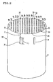
- FIG. 2 is a perspective view exemplarily showing a cell structure usable for another embodiment of the filtering method of the present invention.
- a coagulation membrane filtration test of river surface water was conducted using the above-mentioned cell structures prepared for Examples 1 and 2, and Comparative Example 1, respectively.
Landscapes
- Chemical & Material Sciences (AREA)
- Chemical Kinetics & Catalysis (AREA)
- Engineering & Computer Science (AREA)
- Water Supply & Treatment (AREA)
- Life Sciences & Earth Sciences (AREA)
- Hydrology & Water Resources (AREA)
- Environmental & Geological Engineering (AREA)
- Organic Chemistry (AREA)
- Separation Using Semi-Permeable Membranes (AREA)
Claims (5)
- Filtrationsverfahren, umfassend
die Herstellung einer Wasserreinigungsvorrichtung, umfassend eine Zellenstruktur und einen Deckelabschnitt, wobei die Zellenstruktur so konstruiert ist, dass sie in einer zu den Zellen senkrecht stehenden Richtung eine oder mehrere Einheiten zum Bilden einer Zellenstruktur kombiniert, von denen jede eine Vielzahl von Zellen umfasst, die durch aus einem porösen Körper gebildete Trennwände definiert sind, um Strömungskanäle für Rohwasser zu bilden, und der Deckelabschnitt mit einem an einem anderen Ende ausgebildeten, vorbestimmten Raum angeordnet ist, damit das von einem Ende der Zellenstruktur in die Zellen fließende Rohwasser nicht durch die Zellen hindurchtritt und am anderen Ende ausfließt, wobei das Rohwasser von dem einen Ende der Zellenstruktur der Wasserreinigungsvorrichtung aus in die Zellen einströmen gelassen wird,
das Einströmenlassen von Rohwasser vom einen Ende der Zellenstruktur aus, damit das in die Zellen fließende Rohwasser durch die Trennwände hindurchdringt, um zur Filtration des Rohwassers im Rohwasser enthaltene Fremdstoffe mithilfe der Trennwände zu entfernen, und
die Entnahme von filtriertem Rohwasser als filtriertes Wasser an der Seite einer äußeren Umfangswand der Zellenstruktur,
dadurch gekennzeichnet, dass die Trennwände der Zellenstruktur so konstruiert sind, dass das Verhältnis der Wasserpermeabilität zwischen Trennwänden mit maximaler Wasserpermeabilität und von Trennwänden mit minimaler Wasserpermeabilität der Trennwände als Prozentsatz ausgedrückt innerhalb eines Bereichs von 110 bis 300 % liegt, und worin die am Außenumfang angeordneten Zellen der Zellenstruktur eine höhere Wasserpermeabilität aufweisen, wodurch das von den Zellen mit niedriger Wasserpermeabilität aus in den vorbestimmten Raum des Deckelabschnitts fließende Rohwasser veranlasst wird, in umgekehrter Richtung von dem dem Deckelabschnitt gegenüberliegenden Ende in die Zellen mit höherer Wasserpermeabilität der Zellenstruktur zu strömen und das in umgekehrter Richtung strömende Wasser zur Filtration veranlasst wird, durch die Trennwand hindurchzudringen wonach das filtrierte Rohwasser als Filtratwasser an der Seite der äußeren Umfangsoberfläche der Zellenstruktur entnommen wird. - Filtrationsverfahren nach Anspruch 1, worin die Zellenstruktur eine Zellenstruktur mit zumindest einem schlitzförmig ausgebildeten Wasserkanal mit vorbestimmter Länge ist, der die Trennwände zwischen vorbestimmten Zellen durchdringt; wobei die vorbestimmten Zellen in einem Querschnitt, der die Zellen in einer senkrecht zu den Zellen stehenden Ebene durchschneidet, in etwa linear angeordnet sind; wobei der zumindest eine Wasserkanal so ausgebildet ist, dass er die vorbestimmten Zellen an einem vorbestimmten Abstand zu einer Endfläche der Zellenstruktur zum Zweck der Kommunikation miteinander verbindet; wobei beide Enden der so verbundenen vorbestimmten Zellen der Einheiten zum Bilden der Zellenstruktur mit einem undurchlässigen Material abgedichtet sind; und wobei die Einheiten zum Bilden der Zellenstruktur in Bezug auf die so abgedichteten, vorbestimmten Zellen symmetrisch konfiguriert sind, sodass das Rohwasser zum Zweck der Filtration des Rohwassers veranlasst wird, durch die Zellen, die die Einheiten zum Bilden der Zellenstruktur bilden, zu durchdringen und danach das filtrierte Rohwasser in den Wasserkanal oder in die in Kommunikation mit dem Wasserkanal stehenden vorbestimmten Zellen einströmen gelassen wird, durch den Wasserkanal hindurchtritt und als filtriertes Wasser an einer Seite der äußeren Umfangsoberfläche der Zellenstruktur entnommen wird.
- Filtrationsverfahren nach Anspruch 2, worin die Zellenstruktur eine Zellenstruktur mit drei oder mehr Reihen der Zellen ist, die in etwa parallel zum schlitzartigen Wasserkanal angeordnet sind.
- Filtrationsverfahren nach einem der Ansprüche 1 bis 3, worin die Zellenstruktur aus Keramik gefertigt ist.
- Filtrationsverfahren nach einem der Ansprüche 1 bis 4, worin eine Rückspülung der Einheiten zum Bilden einer Zellenstruktur vorgenommen wird, nachdem das filtrierte Rohwasser an der Seite der äußeren Umfangsoberfläche der Zellenstruktur entnommen wurde, indem das filtrierte Wasser, das bei einem Druck von 200 bis 1000 kPa unter Druck gesetzt ist, von der Seite der äußeren Umfangsoberfläche aus zugeführt wird und die Trennwände durchdringt, wobei die von Trennwänden festgehaltenen Fremdstoffe hinausgedrückt werden und ein unter einem Druck von 100 bis 500 kPa stehendes Gas vom anderen Ende der Zellenstruktur aus einströmen gelassen wird, sodass das filtrierte Wasser gemeinsam mit den Fremdsubstanzen in die Zellen strömt und das Filtratwasser und die Fremdsubstanzen, die in die Zellen einströmen, durch die Zellen hindurchtreten und am Ende der Zellenstruktur an der Seite, von der aus das Rohwasser eingebracht wird, wieder ausfließt.
Applications Claiming Priority (2)
| Application Number | Priority Date | Filing Date | Title |
|---|---|---|---|
| JP2003063414 | 2003-03-10 | ||
| JP2003063414A JP4195824B2 (ja) | 2003-03-10 | 2003-03-10 | ろ過方法 |
Publications (2)
| Publication Number | Publication Date |
|---|---|
| EP1457243A1 EP1457243A1 (de) | 2004-09-15 |
| EP1457243B1 true EP1457243B1 (de) | 2005-08-24 |
Family
ID=32767893
Family Applications (1)
| Application Number | Title | Priority Date | Filing Date |
|---|---|---|---|
| EP04251350A Expired - Lifetime EP1457243B1 (de) | 2003-03-10 | 2004-03-09 | Verfahren zur Filtration |
Country Status (10)
| Country | Link |
|---|---|
| US (1) | US6991737B2 (de) |
| EP (1) | EP1457243B1 (de) |
| JP (1) | JP4195824B2 (de) |
| KR (1) | KR100566362B1 (de) |
| CN (1) | CN1270800C (de) |
| AU (1) | AU2004200982B2 (de) |
| CA (1) | CA2459665C (de) |
| DE (1) | DE602004000058T2 (de) |
| ES (1) | ES2247576T3 (de) |
| TW (1) | TWI259103B (de) |
Families Citing this family (17)
| Publication number | Priority date | Publication date | Assignee | Title |
|---|---|---|---|---|
| JP4195824B2 (ja) * | 2003-03-10 | 2008-12-17 | メタウォーター株式会社 | ろ過方法 |
| JP2004275907A (ja) * | 2003-03-17 | 2004-10-07 | Ngk Insulators Ltd | セラミックフィルタ |
| EP1745837B1 (de) * | 2004-05-13 | 2014-07-09 | Metawater Co., Ltd. | Rückwaschverfahren für filtermembran |
| JP4607634B2 (ja) * | 2005-03-22 | 2011-01-05 | 日本碍子株式会社 | セラミックフィルタ |
| WO2007004263A1 (ja) * | 2005-06-30 | 2007-01-11 | Ngk Insulators, Ltd. | 濾過器 |
| JP2007237053A (ja) * | 2006-03-07 | 2007-09-20 | Ngk Insulators Ltd | 濾過器及び濾過器の逆洗方法 |
| DE102009040110A1 (de) * | 2009-09-04 | 2011-03-10 | Vws Deutschland Gmbh | Kondensatreinigungsanlage |
| CN103068472B (zh) * | 2010-10-26 | 2015-04-29 | 陶氏环球技术有限责任公司 | 包括具不同渗透率区域的膜片的螺旋卷组件 |
| JP6060074B2 (ja) * | 2011-04-25 | 2017-01-11 | 日本碍子株式会社 | セラミックフィルターの洗浄方法 |
| US9932648B2 (en) | 2011-10-31 | 2018-04-03 | Ut-Battelle, Llc | Flow-through pretreatment of lignocellulosic biomass with inorganic nanoporous membranes |
| WO2013066841A1 (en) * | 2011-10-31 | 2013-05-10 | Ut-Battelle Llc | Inorganic nanoporous membranes for high temperature pretreatment of lignocellulosic biomass |
| CN106103384A (zh) | 2014-03-28 | 2016-11-09 | 日本碍子株式会社 | 整体型基材、整体型分离膜结构体及整体型基材的制造方法 |
| CN108348860A (zh) * | 2015-08-10 | 2018-07-31 | 纳诺斯通水务公司 | 具有凹膜的陶瓷膜组件及相关方法 |
| WO2018092342A1 (ja) * | 2016-11-15 | 2018-05-24 | 住友電気工業株式会社 | 濾過モジュール及び濾過装置 |
| FR3074060B1 (fr) | 2017-11-30 | 2023-04-28 | Saint Gobain Ct Recherches | Structure filtrante membranaire monolithique |
| CN111054213B (zh) * | 2019-12-23 | 2024-11-15 | 上海世浦泰膜科技有限公司 | 一种自清洗滤布过滤器 |
| CN113198233B (zh) * | 2021-05-07 | 2022-07-12 | 中节能兆盛环保有限公司 | 一种过滤管网板格栅 |
Family Cites Families (14)
| Publication number | Priority date | Publication date | Assignee | Title |
|---|---|---|---|---|
| US4781831A (en) * | 1986-12-19 | 1988-11-01 | Goldsmith Robert L | Cross-flow filtration device with filtrate flow conduits and method of forming same |
| US5009781A (en) * | 1987-04-02 | 1991-04-23 | Ceramem Corporation | Cross-flow filtration device with filtrate network and method of forming same |
| US5108601A (en) * | 1987-04-02 | 1992-04-28 | Ceramem Corporation | Cross-flow filtration device with filtrate chambers and internal filtrate collection volume |
| JPH0688918A (ja) | 1991-11-07 | 1994-03-29 | Nec Corp | 光導波路デバイスおよびその製造方法 |
| JPH0616819A (ja) | 1992-07-02 | 1994-01-25 | Teijin Chem Ltd | ポリカーボネート粉粒体の製造法 |
| JPH0699039A (ja) | 1992-09-21 | 1994-04-12 | Noritake Co Ltd | モノリス型セラミックフィルター |
| DE4324347A1 (de) | 1992-07-23 | 1994-01-27 | Noritake Co Ltd | Monolithischer Keramikfilter |
| US6077436A (en) | 1997-01-06 | 2000-06-20 | Corning Incorporated | Device for altering a feed stock and method for using same |
| JP3671108B2 (ja) | 1997-12-17 | 2005-07-13 | 日本碍子株式会社 | モノリス形セラミックフィルタ装置 |
| JPH11169679A (ja) | 1997-12-17 | 1999-06-29 | Ngk Insulators Ltd | モノリス形セラミックフィルタ |
| US6126833A (en) * | 1999-02-22 | 2000-10-03 | Ceramem Corporation | Cross-flow filtration device with filtrate conduit network and method of making same |
| GB2368807B (en) * | 2000-11-07 | 2003-08-27 | E R E Filtration Ltd | Filter system |
| GB2388807A (en) | 2002-05-24 | 2003-11-26 | Automated System Services | Weld gun protective cover |
| JP4195824B2 (ja) * | 2003-03-10 | 2008-12-17 | メタウォーター株式会社 | ろ過方法 |
-
2003
- 2003-03-10 JP JP2003063414A patent/JP4195824B2/ja not_active Expired - Fee Related
-
2004
- 2004-03-05 US US10/792,913 patent/US6991737B2/en not_active Expired - Lifetime
- 2004-03-05 CA CA002459665A patent/CA2459665C/en not_active Expired - Lifetime
- 2004-03-05 TW TW093105954A patent/TWI259103B/zh not_active IP Right Cessation
- 2004-03-08 KR KR1020040015398A patent/KR100566362B1/ko not_active Expired - Lifetime
- 2004-03-09 EP EP04251350A patent/EP1457243B1/de not_active Expired - Lifetime
- 2004-03-09 ES ES04251350T patent/ES2247576T3/es not_active Expired - Lifetime
- 2004-03-09 DE DE602004000058T patent/DE602004000058T2/de not_active Expired - Lifetime
- 2004-03-10 CN CNB2004100084198A patent/CN1270800C/zh not_active Expired - Lifetime
- 2004-03-10 AU AU2004200982A patent/AU2004200982B2/en not_active Expired
Also Published As
| Publication number | Publication date |
|---|---|
| CA2459665A1 (en) | 2004-09-10 |
| CN1270800C (zh) | 2006-08-23 |
| US20040200785A1 (en) | 2004-10-14 |
| AU2004200982A1 (en) | 2004-09-30 |
| CN1530163A (zh) | 2004-09-22 |
| ES2247576T3 (es) | 2006-03-01 |
| TWI259103B (en) | 2006-08-01 |
| US6991737B2 (en) | 2006-01-31 |
| CA2459665C (en) | 2008-07-29 |
| KR20040081035A (ko) | 2004-09-20 |
| EP1457243A1 (de) | 2004-09-15 |
| DE602004000058D1 (de) | 2005-09-29 |
| KR100566362B1 (ko) | 2006-03-31 |
| JP4195824B2 (ja) | 2008-12-17 |
| DE602004000058T2 (de) | 2006-06-08 |
| TW200424004A (en) | 2004-11-16 |
| JP2004267932A (ja) | 2004-09-30 |
| AU2004200982B2 (en) | 2008-11-06 |
Similar Documents
| Publication | Publication Date | Title |
|---|---|---|
| CA2459665C (en) | Filtering method | |
| KR100240857B1 (ko) | 무효 체적이 적은 1회용 박막 모듈 | |
| EP0310632B1 (de) | Kreuzstrom-filtrationsapparat und verfahren zu dessen herstellung | |
| US20110100910A1 (en) | Ceramic dead-end filter, a filter system, a method of filtering and a method of producing a ceramic dead-end filter | |
| JPWO2012147534A1 (ja) | セラミックフィルターの洗浄方法 | |
| WO2006080482A1 (ja) | 選択透過性膜モジュールの製造方法および選択透過性膜モジュール | |
| WO2007004262A1 (ja) | 濾過装置 | |
| JP4437527B2 (ja) | 膜ろ過モジュール | |
| JP4358538B2 (ja) | セラミックフィルタ | |
| JP4433276B2 (ja) | 中空糸膜ろ過モジュールおよびその洗浄方法 | |
| CN100563781C (zh) | 陶瓷过滤器 | |
| JP2004524140A5 (de) | ||
| KR20070092129A (ko) | 여과기 및 여과기의 역세척 방법 | |
| JP2000079329A (ja) | ろ過膜モジュ―ル | |
| JP4264017B2 (ja) | 濾過器 | |
| JP2005270810A (ja) | 濾過装置 | |
| KR102508296B1 (ko) | 고투수성 친수형 셀룰로오스계 중공사 정밀여과막을 이용한 수처리장치 | |
| JP2005270811A (ja) | 濾過器 | |
| JP4271066B2 (ja) | 濾過装置及び濾過装置用ヘッダ | |
| WO2023112977A1 (ja) | 膜エレメント | |
| KR20040072018A (ko) | 고유량 절곡필터 | |
| WO2007004264A1 (ja) | 濾過装置及び濾過装置用ヘッダ |
Legal Events
| Date | Code | Title | Description |
|---|---|---|---|
| PUAI | Public reference made under article 153(3) epc to a published international application that has entered the european phase |
Free format text: ORIGINAL CODE: 0009012 |
|
| AK | Designated contracting states |
Kind code of ref document: A1 Designated state(s): AT BE BG CH CY CZ DE DK EE ES FI FR GB GR HU IE IT LI LU MC NL PL PT RO SE SI SK TR |
|
| AX | Request for extension of the european patent |
Extension state: AL HR LT LV MK |
|
| 17P | Request for examination filed |
Effective date: 20040805 |
|
| GRAP | Despatch of communication of intention to grant a patent |
Free format text: ORIGINAL CODE: EPIDOSNIGR1 |
|
| GRAS | Grant fee paid |
Free format text: ORIGINAL CODE: EPIDOSNIGR3 |
|
| AKX | Designation fees paid |
Designated state(s): CH DE ES FR GB LI NL |
|
| GRAA | (expected) grant |
Free format text: ORIGINAL CODE: 0009210 |
|
| AK | Designated contracting states |
Kind code of ref document: B1 Designated state(s): CH DE ES FR GB LI NL |
|
| REG | Reference to a national code |
Ref country code: GB Ref legal event code: FG4D |
|
| REG | Reference to a national code |
Ref country code: CH Ref legal event code: EP |
|
| REF | Corresponds to: |
Ref document number: 602004000058 Country of ref document: DE Date of ref document: 20050929 Kind code of ref document: P |
|
| REG | Reference to a national code |
Ref country code: ES Ref legal event code: FG2A Ref document number: 2247576 Country of ref document: ES Kind code of ref document: T3 |
|
| ET | Fr: translation filed | ||
| PLBE | No opposition filed within time limit |
Free format text: ORIGINAL CODE: 0009261 |
|
| STAA | Information on the status of an ep patent application or granted ep patent |
Free format text: STATUS: NO OPPOSITION FILED WITHIN TIME LIMIT |
|
| 26N | No opposition filed |
Effective date: 20060526 |
|
| PGFP | Annual fee paid to national office [announced via postgrant information from national office to epo] |
Ref country code: FR Payment date: 20120319 Year of fee payment: 9 |
|
| PGFP | Annual fee paid to national office [announced via postgrant information from national office to epo] |
Ref country code: GB Payment date: 20120307 Year of fee payment: 9 |
|
| PGFP | Annual fee paid to national office [announced via postgrant information from national office to epo] |
Ref country code: NL Payment date: 20120322 Year of fee payment: 9 |
|
| PGFP | Annual fee paid to national office [announced via postgrant information from national office to epo] |
Ref country code: ES Payment date: 20120327 Year of fee payment: 9 |
|
| REG | Reference to a national code |
Ref country code: NL Ref legal event code: V1 Effective date: 20131001 |
|
| GBPC | Gb: european patent ceased through non-payment of renewal fee |
Effective date: 20130309 |
|
| REG | Reference to a national code |
Ref country code: FR Ref legal event code: ST Effective date: 20131129 |
|
| PG25 | Lapsed in a contracting state [announced via postgrant information from national office to epo] |
Ref country code: GB Free format text: LAPSE BECAUSE OF NON-PAYMENT OF DUE FEES Effective date: 20130309 Ref country code: FR Free format text: LAPSE BECAUSE OF NON-PAYMENT OF DUE FEES Effective date: 20130402 |
|
| PG25 | Lapsed in a contracting state [announced via postgrant information from national office to epo] |
Ref country code: NL Free format text: LAPSE BECAUSE OF NON-PAYMENT OF DUE FEES Effective date: 20131001 |
|
| REG | Reference to a national code |
Ref country code: ES Ref legal event code: FD2A Effective date: 20140606 |
|
| PG25 | Lapsed in a contracting state [announced via postgrant information from national office to epo] |
Ref country code: ES Free format text: LAPSE BECAUSE OF NON-PAYMENT OF DUE FEES Effective date: 20130310 |
|
| PGFP | Annual fee paid to national office [announced via postgrant information from national office to epo] |
Ref country code: DE Payment date: 20230131 Year of fee payment: 20 |
|
| PGFP | Annual fee paid to national office [announced via postgrant information from national office to epo] |
Ref country code: CH Payment date: 20230402 Year of fee payment: 20 |
|
| REG | Reference to a national code |
Ref country code: DE Ref legal event code: R071 Ref document number: 602004000058 Country of ref document: DE |
|
| REG | Reference to a national code |
Ref country code: CH Ref legal event code: PL |