EP1455108A1 - Verfahren zur Steuerung einer Kupplung - Google Patents
Verfahren zur Steuerung einer Kupplung Download PDFInfo
- Publication number
- EP1455108A1 EP1455108A1 EP04004632A EP04004632A EP1455108A1 EP 1455108 A1 EP1455108 A1 EP 1455108A1 EP 04004632 A EP04004632 A EP 04004632A EP 04004632 A EP04004632 A EP 04004632A EP 1455108 A1 EP1455108 A1 EP 1455108A1
- Authority
- EP
- European Patent Office
- Prior art keywords
- clutch
- function
- freewheeling
- opened
- speed
- Prior art date
- Legal status (The legal status is an assumption and is not a legal conclusion. Google has not performed a legal analysis and makes no representation as to the accuracy of the status listed.)
- Granted
Links
Images



Classifications
-
- F—MECHANICAL ENGINEERING; LIGHTING; HEATING; WEAPONS; BLASTING
- F16—ENGINEERING ELEMENTS AND UNITS; GENERAL MEASURES FOR PRODUCING AND MAINTAINING EFFECTIVE FUNCTIONING OF MACHINES OR INSTALLATIONS; THERMAL INSULATION IN GENERAL
- F16D—COUPLINGS FOR TRANSMITTING ROTATION; CLUTCHES; BRAKES
- F16D48/00—External control of clutches
- F16D48/06—Control by electric or electronic means, e.g. of fluid pressure
-
- E—FIXED CONSTRUCTIONS
- E01—CONSTRUCTION OF ROADS, RAILWAYS, OR BRIDGES
- E01D—CONSTRUCTION OF BRIDGES, ELEVATED ROADWAYS OR VIADUCTS; ASSEMBLY OF BRIDGES
- E01D22/00—Methods or apparatus for repairing or strengthening existing bridges ; Methods or apparatus for dismantling bridges
-
- E—FIXED CONSTRUCTIONS
- E05—LOCKS; KEYS; WINDOW OR DOOR FITTINGS; SAFES
- E05B—LOCKS; ACCESSORIES THEREFOR; HANDCUFFS
- E05B65/00—Locks or fastenings for special use
-
- E—FIXED CONSTRUCTIONS
- E06—DOORS, WINDOWS, SHUTTERS, OR ROLLER BLINDS IN GENERAL; LADDERS
- E06C—LADDERS
- E06C7/00—Component parts, supporting parts, or accessories
- E06C7/006—Devices for preventing access
-
- E—FIXED CONSTRUCTIONS
- E06—DOORS, WINDOWS, SHUTTERS, OR ROLLER BLINDS IN GENERAL; LADDERS
- E06C—LADDERS
- E06C7/00—Component parts, supporting parts, or accessories
- E06C7/08—Special construction of longitudinal members, or rungs or other treads
-
- E—FIXED CONSTRUCTIONS
- E06—DOORS, WINDOWS, SHUTTERS, OR ROLLER BLINDS IN GENERAL; LADDERS
- E06C—LADDERS
- E06C9/00—Ladders characterised by being permanently attached to fixed structures, e.g. fire escapes
- E06C9/02—Ladders characterised by being permanently attached to fixed structures, e.g. fire escapes rigidly mounted
-
- F—MECHANICAL ENGINEERING; LIGHTING; HEATING; WEAPONS; BLASTING
- F16—ENGINEERING ELEMENTS AND UNITS; GENERAL MEASURES FOR PRODUCING AND MAINTAINING EFFECTIVE FUNCTIONING OF MACHINES OR INSTALLATIONS; THERMAL INSULATION IN GENERAL
- F16D—COUPLINGS FOR TRANSMITTING ROTATION; CLUTCHES; BRAKES
- F16D2500/00—External control of clutches by electric or electronic means
- F16D2500/10—System to be controlled
- F16D2500/108—Gear
- F16D2500/1081—Actuation type
- F16D2500/1085—Automatic transmission
-
- F—MECHANICAL ENGINEERING; LIGHTING; HEATING; WEAPONS; BLASTING
- F16—ENGINEERING ELEMENTS AND UNITS; GENERAL MEASURES FOR PRODUCING AND MAINTAINING EFFECTIVE FUNCTIONING OF MACHINES OR INSTALLATIONS; THERMAL INSULATION IN GENERAL
- F16D—COUPLINGS FOR TRANSMITTING ROTATION; CLUTCHES; BRAKES
- F16D2500/00—External control of clutches by electric or electronic means
- F16D2500/30—Signal inputs
- F16D2500/308—Signal inputs from the transmission
- F16D2500/30806—Engaged transmission ratio
-
- F—MECHANICAL ENGINEERING; LIGHTING; HEATING; WEAPONS; BLASTING
- F16—ENGINEERING ELEMENTS AND UNITS; GENERAL MEASURES FOR PRODUCING AND MAINTAINING EFFECTIVE FUNCTIONING OF MACHINES OR INSTALLATIONS; THERMAL INSULATION IN GENERAL
- F16D—COUPLINGS FOR TRANSMITTING ROTATION; CLUTCHES; BRAKES
- F16D2500/00—External control of clutches by electric or electronic means
- F16D2500/30—Signal inputs
- F16D2500/31—Signal inputs from the vehicle
- F16D2500/3108—Vehicle speed
-
- F—MECHANICAL ENGINEERING; LIGHTING; HEATING; WEAPONS; BLASTING
- F16—ENGINEERING ELEMENTS AND UNITS; GENERAL MEASURES FOR PRODUCING AND MAINTAINING EFFECTIVE FUNCTIONING OF MACHINES OR INSTALLATIONS; THERMAL INSULATION IN GENERAL
- F16D—COUPLINGS FOR TRANSMITTING ROTATION; CLUTCHES; BRAKES
- F16D2500/00—External control of clutches by electric or electronic means
- F16D2500/30—Signal inputs
- F16D2500/312—External to the vehicle
- F16D2500/3124—Driving conditions, e.g. climbing hills, cornering, traffic
-
- F—MECHANICAL ENGINEERING; LIGHTING; HEATING; WEAPONS; BLASTING
- F16—ENGINEERING ELEMENTS AND UNITS; GENERAL MEASURES FOR PRODUCING AND MAINTAINING EFFECTIVE FUNCTIONING OF MACHINES OR INSTALLATIONS; THERMAL INSULATION IN GENERAL
- F16D—COUPLINGS FOR TRANSMITTING ROTATION; CLUTCHES; BRAKES
- F16D2500/00—External control of clutches by electric or electronic means
- F16D2500/30—Signal inputs
- F16D2500/312—External to the vehicle
- F16D2500/3125—Driving resistance, i.e. external factors having an influence in the traction force, e.g. road friction, air resistance, road slope
- F16D2500/3127—Road slope
-
- F—MECHANICAL ENGINEERING; LIGHTING; HEATING; WEAPONS; BLASTING
- F16—ENGINEERING ELEMENTS AND UNITS; GENERAL MEASURES FOR PRODUCING AND MAINTAINING EFFECTIVE FUNCTIONING OF MACHINES OR INSTALLATIONS; THERMAL INSULATION IN GENERAL
- F16D—COUPLINGS FOR TRANSMITTING ROTATION; CLUTCHES; BRAKES
- F16D2500/00—External control of clutches by electric or electronic means
- F16D2500/30—Signal inputs
- F16D2500/314—Signal inputs from the user
- F16D2500/31406—Signal inputs from the user input from pedals
- F16D2500/3144—Accelerator pedal position
-
- F—MECHANICAL ENGINEERING; LIGHTING; HEATING; WEAPONS; BLASTING
- F16—ENGINEERING ELEMENTS AND UNITS; GENERAL MEASURES FOR PRODUCING AND MAINTAINING EFFECTIVE FUNCTIONING OF MACHINES OR INSTALLATIONS; THERMAL INSULATION IN GENERAL
- F16D—COUPLINGS FOR TRANSMITTING ROTATION; CLUTCHES; BRAKES
- F16D2500/00—External control of clutches by electric or electronic means
- F16D2500/30—Signal inputs
- F16D2500/314—Signal inputs from the user
- F16D2500/31493—Switches on the dashboard
-
- F—MECHANICAL ENGINEERING; LIGHTING; HEATING; WEAPONS; BLASTING
- F16—ENGINEERING ELEMENTS AND UNITS; GENERAL MEASURES FOR PRODUCING AND MAINTAINING EFFECTIVE FUNCTIONING OF MACHINES OR INSTALLATIONS; THERMAL INSULATION IN GENERAL
- F16D—COUPLINGS FOR TRANSMITTING ROTATION; CLUTCHES; BRAKES
- F16D2500/00—External control of clutches by electric or electronic means
- F16D2500/70—Details about the implementation of the control system
- F16D2500/704—Output parameters from the control unit; Target parameters to be controlled
- F16D2500/70402—Actuator parameters
- F16D2500/7041—Position
Definitions
- the present invention relates to a method for controlling a clutch, the between a drive motor and an automatic manual transmission Drive train is arranged.
- Drive trains for motor vehicles are known from the prior art, in which a manual transmission is connected to the drive motor via a clutch, wherein both manual transmission and clutch are operated automatically.
- Gearboxes or drivetrains are generally called automated manual transmissions designated.
- Vehicles in which the engine and output are connected via a friction clutch can cause vibrations between the engine and the drive train when the load changes stimulate towards the vehicle. Especially with large translations, this is generally the case at low speeds, these vibrations on the output noticeable. While this effect is accepted by the driver in manual transmissions, is the demand for comfort in automated systems is significantly higher.
- the object of the present invention is therefore to reduce vibrations during load changes to decrease.
- the clutch is preferably opened to implement the freewheel function. Entry conditions for the freewheel function may be that the gear is smaller or is equal to a maximum gear and / or that the clutch for implementation the freewheeling function is opened when the accelerator pedal is not operated, and / or that an idle switch is activated and / or that the driver's desired torque is less than zero and / or that in addition the speed is lower than the maximum Freewheeling speed is and / or if there is no downhill driving through a Control device or the like is recognized and / or that the transmission in one Automatic driving program is switched and / or that a crawl function is not activated and / or that the freewheel function is not blocked.
- the freewheeling function is activated with or blocked several of the following conditions: when the driving speed is greater than the maximum freewheeling speed if there is no automatic driving program is activated or if a mountain program is activated. More can also be found here Conditions.
- the lock remains active until at least one of the following conditions is fulfilled: when the accelerator pedal is operated or the driver's desired torque is greater than It is zero if there is a change from a manual to an automatic driving program or if a gear change with a gear less than or equal to the maximum Free emergence occurs. Other conditions can also be used here.
- the problem mentioned at the outset is also a drive train in particular for a motor vehicle comprising a drive motor, a manual transmission and one of these connecting clutch released, in which the drive train is a control system, according to one of the previous methods may include.
- Figures 1 to 6 are schematic representations of the Course of the speed n and the engine torque M over the time t of the engine.
- Fig. 1 Shown in Fig. 1 is the idle speed 1 and the engine speed 2 over time t.
- the freewheeling phase 3 which is shown as a vertical line in FIG. 1, becomes the vehicle clutch, the known one not shown here Drive motor with an automated manual transmission, not shown here connects, open.
- the clutch is controlled automatically by a for example electrical actuator.
- the gearbox is also shifted by, for example, electrically driven actuators.
- Such a drive train or the associated transmission and its circuit is generally considered automated Designated manual transmission.
- the engine speed n drops Start of freewheeling phase 3 to idle speed 1.
- the associated torque curve M over time t can be seen from FIG.
- the engine torque M M and the clutch torque M K are shown .
- the clutch torque decreases with the start of the freewheeling phase 3, which is represented by a vertical line in FIG. 1, to a clutch torque M K from zero, while the engine torque M M increases to a freewheel torque 5 after the clutch is finally open.
- the torque curve M M is shown in regular coasting operation, in this case a negative drag torque 4 is transmitted to the engine via the clutch.
- Fig. 3 shows the re-engagement without engine intervention, the speed of the engine being adjusted to the speed of the transmission input shaft before engagement. The aim is to ensure that the clutch is practically imperceptible to the driver.
- 3 shows the speed n over time t.
- the gear speed N G is drawn in as a horizontal line. According to the representation of FIG. 1 as a horizontal line, the idling speed 1 of the engine is also shown.
- the freewheeling phase 6, the run-up phase 7 and the engagement phase 8 are shown over time.
- the engine speed n M is increased so that it is above the transmission speed during the engagement phase.
- the gearbox speed is measured on the clutch. When the clutch is continuously closed from a clutch closing time 9, the speed drops to the transmission speed N G until the clutch is fully closed.
- the associated engine torque M M and the associated clutch torque M K are shown in FIG. 4.
- the clutch torque M K is controlled during the run-up phase of the engine to a comparatively low value for tensioning the drive train and then during the clutch-in phase to the engine torque M M and even briefly beyond. When engaged, the clutch torque M K corresponds to the engine torque M M.
- FIGS. 5 and 6 show speed n as well as the previous representations Moment M over time t.
- the speed curve shown in FIG. 5, roughly follows that shown in FIG. 3 Speed curve.
- the torque curve shown in FIG. 6 is too recognize that the engine torque is not regulated to a constant value then to enter the coupling phase 8, but first to a relatively high one regulated value, which then returns to a value after the start of the engagement phase comparatively low value is reduced.
- the driving gear should be less than or equal to a maximum Be free range.
- the maximum clearance is a predetermined highest gear, in which the drivetrain may be converted into the freewheel function.
- the accelerator pedal is not operated, an idle switch is actively closed by the driver switch or the driver's desired torque should be less than zero.
- An additional The condition is that the driving speed is less than a maximum Freewheeling speed is. Above the maximum freewheel speed, this will be Vehicle also not transferred to the freewheel function. The freewheel function will also not switched on if a downhill trip was detected. The The freewheel function is only switched on if an automatic drive program is selected and no crawl function is activated.
- the freewheel function is blocked when various conditions occur.
- a ban occurs when the driving speed is greater than the maximum freewheeling speed is.
- Locking also takes place if no automatic drive program has been selected and when a mountain program is activated. The lock remains active until the Accelerator pedal is pressed or the driver's desired torque is greater than zero until a change from a manual drive program to an automatic drive program or up to Changing gears with a gear less than or equal to the maximum open space he follows. As soon as one of the entry conditions is no longer met, will be back engaged. A distinction must be made between push and pull operations. in the Overrun, the clutch is closed slowly or a creep torque built up.
- the clutch only closes then when the engine speed is above the transmission input speed.
- the clutch engagement function in train operation is critical to comfort, since the driver during the Turning the engine up does not receive the desired output torque and then must be engaged relatively quickly to prevent the engine from turning away.
- the clutch has proven to be beneficial for the clutch to be slightly just a few Newton meters. On the one hand, the dead time for Bridging the airway of the clutch can be reduced and secondly the Clearance run of the input shaft defined to be run through at a small moment.
- the clutch must be so fast that the engine cannot be overturned can be. With a reduced torque requirement for the engine control Rough coupling processes or excessive engine overspeed can be dragged become.
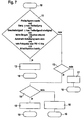
- FIG. 7 shows a flow chart for the sequence of the freewheeling function
- 8 shows a flowchart for determining the freewheel lock.
- a second test step 13 checked whether the accelerator pedal is depressed or the driver's desired torque is greater than zero Newton meter is. If this is the case, it is checked in a third test step 14 whether the Engine speed is greater than the gearbox speed. If this is the case, there is one Coupling phase with coupling in train 15 before, whereupon the entire test run with one end 16 is ended. If the second test step 13 was answered in the negative, there is one Engaging phase with engaging in overrun or with a creeping moment in body 17 before, in turn, the end 16 is driven. Was the third test step 14 no, there is a start-up phase in which a small clutch torque is applied should be 18, before, in turn, the end 16 is driven.
- step 8 shows a flowchart for determining the freewheel lock.
- start 19 is first checked in a step 20 whether a continuous driving program is inactive or the Speed is greater than the maximum freewheeling speed or a downhill situation is activated. If this is the case, the freewheel lock is activated in a step 21 activated. If the test in step 20 was answered in the negative, the first step is step 22 checked whether the accelerator pedal is depressed and is therefore greater than zero or the target gear is smaller or equal to the maximum open space or a switch between manual Shift and automatic shift is present. If this is the case, then in a step 23 the drive lock is deactivated. If the test in step 22 was answered in the negative, it will Program ended directly in step 24.
Landscapes
- Engineering & Computer Science (AREA)
- Mechanical Engineering (AREA)
- General Engineering & Computer Science (AREA)
- Physics & Mathematics (AREA)
- Fluid Mechanics (AREA)
- Architecture (AREA)
- Civil Engineering (AREA)
- Structural Engineering (AREA)
- Hydraulic Clutches, Magnetic Clutches, Fluid Clutches, And Fluid Joints (AREA)
- Control Of Driving Devices And Active Controlling Of Vehicle (AREA)
- Control Of Transmission Device (AREA)
Abstract
Description
- Fig. 1
- einen Drehzahlverlauf über der Zeit beim Übergang in den Freilauf;
- Fig. 2
- einen Momentenverlauf über der Zeit beim Übergang in den Freilauf;
- Fig. 3
- einen Drehzahlverlauf beim Wiedereinkuppeln ohne Motor-Momenteneingriff;
- Fig. 4
- einen Drehmomentenverlauf beim Wiedereinkuppeln ohne Motor-Momenteneingriff;
- Fig. 5
- einen Drehzahlverlauf über der Zeit beim Wiedereinkuppeln mit Motor-Momenteneingriff;
- Fig. 6
- einen Momentenverlauf beim Wiedereinkuppeln mit Motor-Momenteneingriff;
- Fig. 7
- ein Flussdiagramm zum Ablauf der Freilauffunktion;
- Fig. 8
- ein Flussdiagramm zur Bestimmung der Freilaufsperre.
- n
- Drehzahl
- nM
- Motordrehzahl
- M
- Moment
- MM
- Motormoment
- MK
- Kupplung
- nG
- Getriebedrehzahl
- t
- Zeit
- 1
- Leerlaufdrehzahl
- 2
- Motordrehzahl
- 3
- Beginn Freilaufphase
- 4
- Schleppmoment
- 5
- Freilaufmoment
- 6
- Freilaufphase
- 7
- Hochlaufphase
- 8
- Einkuppelphase
- 9
- Kupplungsschließzeitpunkt
- 10
- Startpunkt
- 11
- Erster Prüfschritt
- 12
- Freilaufphase
- 13
- Zweiter Prüfschritt
- 14
- Dritter Prüfschritt
- 15
- Einkuppelphase
- 16
- Ende
- 17
- Einkuppeln im Schub / Kriechmomentenaufbau
- 18
- Hochlaufphase mit kleinem Kupplungsmoment
- 19
- Start
- 20
- Prüfung Dauerfahrprogramm, Geschwindigkeit, etc.
- 21
- Aktivierung Freilaufsperre
- 22
- Fahrpedal betätigt?
- 23
- Deaktivierung Freilaufsperre
- 24
- Ende
Claims (18)
- Verfahren zur Steuerung einer Kupplung, die zwischen einem Antriebsmotor und einem automatischen Schaltgetriebe eines Antriebsstranges angeordnet ist, dadurch gekennzeichnet, dass die Kupplung derart gesteuert wird, dass im Schubbetrieb eine Freilauffunktion realisiert wird.
- Verfahren nach Anspruch 1, dadurch gekennzeichnet, dass die Kupplung zur Realisierung der Freilauffunktion geöffnet wird.
- Verfahren nach einem der vorhergehenden Ansprüche, dadurch gekennzeichnet, dass die Kupplung zur Realisierung der Freilauffunktion geöffnet wird, wenn der Fahrgang kleiner oder gleich einem maximalen Freilaufgang ist.
- Verfahren nach einem der vorhergehenden Ansprüche, dadurch gekennzeichnet, dass die Kupplung zur Realisierung der Freilauffunktion geöffnet wird, wenn das Fahrpedal nicht betätigt wird.
- Verfahren nach einem der vorhergehenden Ansprüche, dadurch gekennzeichnet, dass die Kupplung zur Realisierung der Freilauffunktion geöffnet wird, wenn ein Leerlaufschalter aktiviert ist.
- Verfahren nach einem der vorhergehenden Ansprüche, dadurch gekennzeichnet, dass die Kupplung zur Realisierung der Freilauffunktion geöffnet wird, wenn das Fahrerwunschmoment kleiner als Null ist.
- Verfahren nach einem der vorhergehenden Ansprüche, dadurch gekennzeichnet, dass die Kupplung zur Realisierung der Freilauffunktion geöffnet wird, wenn die Fahrgeschwindigkeit kleiner als die maximale Freilaufgeschwindigkeit ist.
- Verfahren nach einem der vorhergehenden Ansprüche, dadurch gekennzeichnet, dass die Kupplung zur Realisierung der Freilauffunktion geöffnet wird, wenn keine Bergab-Fahrt erkannt wird.
- Verfahren nach einem der vorhergehenden Ansprüche, dadurch gekennzeichnet, dass die Kupplung zur Realisierung der Freilauffunktion geöffnet wird, wenn das Getriebe in ein Automatik-Fahrprogramm geschaltet ist.
- Verfahren nach einem der vorhergehenden Ansprüche, dadurch gekennzeichnet, dass die Kupplung zur Realisierung der Freilauffunktion geöffnet wird, wenn eine Kriechfunktion nicht aktiviert ist.
- Verfahren nach einem der vorhergehenden Ansprüche, dadurch gekennzeichnet, dass die Kupplung zur Realisierung der Freilauffunktion geöffnet wird, wenn keine Sperrung der Freilauffunktion vorliegt.
- Verfahren nach einem der vorhergehenden Ansprüche, dadurch gekennzeichnet, dass die Freilauffunktion gesperrt wird, wenn die Fahrgeschwindigkeit größer als die maximale Freilaufgeschwindigkeit ist.
- Verfahren nach einem der vorhergehenden Ansprüche, dadurch gekennzeichnet, dass die Freilauffunktion gesperrt wird, wenn kein Automatik-Fahrprogramm aktiviert ist.
- Verfahren nach einem der vorhergehenden Ansprüche, dadurch gekennzeichnet, dass die Freilauffunktion gesperrt wird, wenn ein Bergprogramm aktiviert ist.
- Verfahren nach einem der vorhergehenden Ansprüche, dadurch gekennzeichnet, dass die Sperrung der Freilauffunktion deaktiviert wird, wenn das Fahrpedal betätigt wird oder das Fahrerwunschmoment größer als Null ist.
- Verfahren nach einem der vorhergehenden Ansprüche, dadurch gekennzeichnet, dass die Sperrung der Freilauffunktion deaktiviert wird, wenn ein Wechsel von einem manuellen in ein Automatik-Fahrprogramm erfolgt.
- Verfahren nach einem der vorhergehenden Ansprüche, dadurch gekennzeichnet, dass die Sperrung der Freilauffunktion deaktiviert wird, wenn ein Gangwechsel mit einem Fahrgang kleiner oder gleich dem maximalen Freilaufgang erfolgt.
- Antriebsstrang insbesondere für ein Kraftfahrzeug, umfassend einen Antriebsmotor, ein Schaltgetriebe, eine diese verbindende Kupplung, dadurch gekennzeichnet, dass der Antriebsstrang eine Steuerung, die nach einem der vorhergehenden Verfahren arbeiten kann, umfasst
Applications Claiming Priority (2)
| Application Number | Priority Date | Filing Date | Title |
|---|---|---|---|
| DE10309723 | 2003-03-06 | ||
| DE10309723 | 2003-03-06 |
Publications (2)
| Publication Number | Publication Date |
|---|---|
| EP1455108A1 true EP1455108A1 (de) | 2004-09-08 |
| EP1455108B1 EP1455108B1 (de) | 2006-08-30 |
Family
ID=32797836
Family Applications (1)
| Application Number | Title | Priority Date | Filing Date |
|---|---|---|---|
| EP04004632A Expired - Lifetime EP1455108B1 (de) | 2003-03-06 | 2004-03-01 | Verfahren zur Steuerung einer Kupplung |
Country Status (7)
| Country | Link |
|---|---|
| US (1) | US8057356B2 (de) |
| EP (1) | EP1455108B1 (de) |
| JP (1) | JP2004270944A (de) |
| KR (1) | KR20040078916A (de) |
| AT (1) | ATE338222T1 (de) |
| BR (1) | BRPI0400701A (de) |
| DE (2) | DE102004009833B4 (de) |
Cited By (4)
| Publication number | Priority date | Publication date | Assignee | Title |
|---|---|---|---|---|
| WO2010149126A1 (de) * | 2009-06-25 | 2010-12-29 | Schaeffler Technologies Gmbh & Co. Kg | Antriebsstrang mit kupplungsansteuerung zur überwindung seines verdrehspiels vor dem anfahren |
| FR2995857A1 (fr) * | 2012-09-26 | 2014-03-28 | Renault Sa | "procede de commande en roue libre d'une chaine de traction de vehicule a propulsion electrique" |
| EP2894316A4 (de) * | 2012-09-03 | 2016-05-11 | Toyota Motor Co Ltd | Fahrzeugfahrtsteuerungsvorrichtung |
| FR3047955A1 (fr) * | 2016-02-19 | 2017-08-25 | Renault Sas | Systeme complementaire de commande d’un embrayage de vehicule |
Families Citing this family (12)
| Publication number | Priority date | Publication date | Assignee | Title |
|---|---|---|---|---|
| DE102005003608A1 (de) * | 2005-01-26 | 2006-08-03 | Zf Friedrichshafen Ag | Verfahren zum Betreiben des Antriebsstranges eines Fahrzeuges |
| CN101263036A (zh) * | 2005-09-08 | 2008-09-10 | 沃尔沃拉斯特瓦格纳公司 | 用于激活车辆的惯性滑行功能的方法 |
| EP2071213B1 (de) * | 2007-12-11 | 2014-12-03 | General Electric Company | Getrieberauschunterdrückung durch elektrische Antriebssteuerung |
| JP5169910B2 (ja) * | 2009-03-04 | 2013-03-27 | いすゞ自動車株式会社 | 惰行制御装置 |
| JP5169932B2 (ja) * | 2009-03-24 | 2013-03-27 | いすゞ自動車株式会社 | 惰行制御装置 |
| US8187149B2 (en) | 2009-07-16 | 2012-05-29 | GM Global Technology Operations LLC | Coasting control systems and methods for automatic transmission |
| JP5403368B2 (ja) * | 2010-02-26 | 2014-01-29 | アイシン・エィ・ダブリュ株式会社 | 車両用駆動装置 |
| JP5778396B2 (ja) * | 2010-07-30 | 2015-09-16 | いすゞ自動車株式会社 | 惰行制御装置 |
| WO2012111062A1 (ja) * | 2011-02-14 | 2012-08-23 | トヨタ自動車株式会社 | 車両制御装置 |
| WO2015041044A1 (ja) * | 2013-09-20 | 2015-03-26 | トヨタ自動車株式会社 | 車両の制御装置 |
| JP2015068387A (ja) * | 2013-09-27 | 2015-04-13 | トヨタ自動車株式会社 | 車両の制御装置 |
| DE102015208236A1 (de) * | 2015-05-05 | 2016-11-10 | Schaeffler Technologies AG & Co. KG | Verfahren zur Steuerung einer Kupplung eines Fahrzeuges nach Beendigung eines Segelbetriebes des Fahrzeuges |
Citations (6)
| Publication number | Priority date | Publication date | Assignee | Title |
|---|---|---|---|---|
| DE3041501A1 (de) * | 1980-11-04 | 1982-06-09 | Volkswagenwerk Ag | Fahrzeug, insbesondere personenkraftfahrzeug |
| DE4011850A1 (de) * | 1989-04-17 | 1990-10-18 | Luk Lamellen & Kupplungsbau | Verfahren zum steuern einer zwischen einer antriebsmaschine und einem getriebe wirksamen automatisierten reibungskupplung und einrichtung zur durchfuehrung des verfahrens sowie regelung fuer eine reibungskupplung |
| DE19532946A1 (de) * | 1995-09-07 | 1997-03-13 | Volkswagen Ag | Steuerungseinrichtung zur Steuerung des Motorbremsbetriebes eines Kraftfahrzeuges |
| EP0937904A2 (de) * | 1998-02-23 | 1999-08-25 | Isuzu Motors Limited | Fahrzeug mit automatisch gesteuerter Kupplung |
| DE10221701A1 (de) * | 2001-05-21 | 2002-11-28 | Luk Lamellen & Kupplungsbau | Steuerverfahren für Kraftfahrzeuge mit automatisierter Kupplungsvorrichtung |
| WO2003076227A1 (en) * | 2002-03-13 | 2003-09-18 | Volvo Lastvagnar Ab | Transmission device for motor vehicle |
Family Cites Families (11)
| Publication number | Priority date | Publication date | Assignee | Title |
|---|---|---|---|---|
| JPS5842050B2 (ja) * | 1973-12-18 | 1983-09-16 | 日産自動車株式会社 | ジドウシヤ ノ ダセイソウコウソウチ |
| JPS6011770A (ja) * | 1983-06-29 | 1985-01-22 | Isuzu Motors Ltd | 自動クラツチ付自動変速機のクラツチ制御法 |
| JPS60229830A (ja) * | 1984-04-27 | 1985-11-15 | Mitsubishi Heavy Ind Ltd | 自動車 |
| FR2645805B1 (fr) * | 1989-04-17 | 1995-07-13 | Luk Lamellen & Kupplungsbau | Procede de commande d'un embrayage a friction automatise agissant entre un moteur d'entrainement et une transmission, appareillage pour la mise en oeuvre du procede, et regulation associee d'un embrayage a friction |
| US5425689A (en) * | 1992-07-06 | 1995-06-20 | Eaton Corporation | Engine brake enhanced upshift control method/system |
| GB9219101D0 (en) * | 1992-09-09 | 1992-10-21 | Automotive Products Plc | A clutch control system |
| JP2927153B2 (ja) * | 1993-09-10 | 1999-07-28 | トヨタ自動車株式会社 | 車両用ロックアップクラッチの制御装置 |
| GB9505174D0 (en) * | 1995-03-15 | 1995-05-03 | Automotive Products Plc | Vehicle transmissions |
| JP2004512472A (ja) * | 2000-04-03 | 2004-04-22 | ルーク ラメレン ウント クツプルングスバウ ベタイリグングス コマンディートゲゼルシャフト | 変速機 |
| JP2001304305A (ja) * | 2000-04-18 | 2001-10-31 | Mitsubishi Motors Corp | 機械式自動変速機の変速制御装置 |
| JP3659212B2 (ja) * | 2001-10-22 | 2005-06-15 | 日産自動車株式会社 | 歯車変速機の自動クラッチ制御装置 |
-
2004
- 2004-02-28 DE DE102004009833.6A patent/DE102004009833B4/de not_active Expired - Fee Related
- 2004-03-01 AT AT04004632T patent/ATE338222T1/de not_active IP Right Cessation
- 2004-03-01 EP EP04004632A patent/EP1455108B1/de not_active Expired - Lifetime
- 2004-03-01 DE DE502004001296T patent/DE502004001296D1/de not_active Expired - Lifetime
- 2004-03-02 US US10/791,432 patent/US8057356B2/en not_active Expired - Fee Related
- 2004-03-05 JP JP2004062767A patent/JP2004270944A/ja not_active Withdrawn
- 2004-03-05 KR KR1020040014969A patent/KR20040078916A/ko not_active Withdrawn
- 2004-03-05 BR BR0400701-8A patent/BRPI0400701A/pt not_active IP Right Cessation
Patent Citations (6)
| Publication number | Priority date | Publication date | Assignee | Title |
|---|---|---|---|---|
| DE3041501A1 (de) * | 1980-11-04 | 1982-06-09 | Volkswagenwerk Ag | Fahrzeug, insbesondere personenkraftfahrzeug |
| DE4011850A1 (de) * | 1989-04-17 | 1990-10-18 | Luk Lamellen & Kupplungsbau | Verfahren zum steuern einer zwischen einer antriebsmaschine und einem getriebe wirksamen automatisierten reibungskupplung und einrichtung zur durchfuehrung des verfahrens sowie regelung fuer eine reibungskupplung |
| DE19532946A1 (de) * | 1995-09-07 | 1997-03-13 | Volkswagen Ag | Steuerungseinrichtung zur Steuerung des Motorbremsbetriebes eines Kraftfahrzeuges |
| EP0937904A2 (de) * | 1998-02-23 | 1999-08-25 | Isuzu Motors Limited | Fahrzeug mit automatisch gesteuerter Kupplung |
| DE10221701A1 (de) * | 2001-05-21 | 2002-11-28 | Luk Lamellen & Kupplungsbau | Steuerverfahren für Kraftfahrzeuge mit automatisierter Kupplungsvorrichtung |
| WO2003076227A1 (en) * | 2002-03-13 | 2003-09-18 | Volvo Lastvagnar Ab | Transmission device for motor vehicle |
Cited By (6)
| Publication number | Priority date | Publication date | Assignee | Title |
|---|---|---|---|---|
| WO2010149126A1 (de) * | 2009-06-25 | 2010-12-29 | Schaeffler Technologies Gmbh & Co. Kg | Antriebsstrang mit kupplungsansteuerung zur überwindung seines verdrehspiels vor dem anfahren |
| US8584545B2 (en) | 2009-06-25 | 2013-11-19 | Schaeffler Technologies AG & Co. KG | Drive train having clutch activation for overcoming the backlash of the drive train before start-up |
| EP2894316A4 (de) * | 2012-09-03 | 2016-05-11 | Toyota Motor Co Ltd | Fahrzeugfahrtsteuerungsvorrichtung |
| US9656655B2 (en) | 2012-09-03 | 2017-05-23 | Toyota Jidosha Kabushiki Kaisha | Running control system for vehicle |
| FR2995857A1 (fr) * | 2012-09-26 | 2014-03-28 | Renault Sa | "procede de commande en roue libre d'une chaine de traction de vehicule a propulsion electrique" |
| FR3047955A1 (fr) * | 2016-02-19 | 2017-08-25 | Renault Sas | Systeme complementaire de commande d’un embrayage de vehicule |
Also Published As
| Publication number | Publication date |
|---|---|
| US20040176213A1 (en) | 2004-09-09 |
| BRPI0400701A (pt) | 2005-01-11 |
| KR20040078916A (ko) | 2004-09-13 |
| ATE338222T1 (de) | 2006-09-15 |
| DE102004009833A1 (de) | 2004-09-16 |
| JP2004270944A (ja) | 2004-09-30 |
| US8057356B2 (en) | 2011-11-15 |
| EP1455108B1 (de) | 2006-08-30 |
| DE502004001296D1 (de) | 2006-10-12 |
| DE102004009833B4 (de) | 2019-12-19 |
Similar Documents
| Publication | Publication Date | Title |
|---|---|---|
| EP2417378B1 (de) | Verfahren zum betreiben eines fahrzeugantriebsstranges | |
| DE10080639B4 (de) | Kupplungssteuervorrichtung zur automatischen Betätigung einer Kupplung während des Anfahrens | |
| DE10230612B4 (de) | Verfahren zum Betrieb eines Kraftfahrzeuges, insbesondere zum Verbessern eines Anfahrvorganges | |
| EP2342112B1 (de) | Verfahren zur steuerung eines automatisierten stufenschaltgetriebes | |
| EP0589916B1 (de) | Verfahren zur steuerung eines stufenlosen getriebes eines kraftfahrzeugs | |
| DE102004009833B4 (de) | Verfahren zur Steuerung einer Kupplung und Antriebsstrang | |
| WO1993000535A1 (de) | Verfahren zur steuerung eines automatisch betätigten getriebes eines kraftfahrzeugs | |
| DE112014004582B4 (de) | Verfahren zur Steuerung eines Antriebsstrangs mit einem Doppelkupplungsgetriebe | |
| EP1899190A1 (de) | Verfahren zum steuern eines antriebsstranges eines fahrzeugs mit einer antriebsmaschine und mit einem getriebe | |
| EP1855021B1 (de) | Verfahren zum Anfahren bei Brennkraftmaschinen mit Doppelkupplungsgetriebe | |
| DE102019110766A1 (de) | Bewertung einer drehmomentwandlerkupplungsposition basierend auf dem angesammelten schlupf | |
| DE102007003726A1 (de) | Verfahren zum Betreiben eines Fahrzeugantriebsstranges | |
| WO2005065982A1 (de) | Schaltverfahren bei einem sensorausfall für ein automatisiertes schaltklauengetriebe | |
| EP1716349B1 (de) | Verfahren zur verhinderung von lastwechselschlägen bei einem kraftfahrzeug | |
| EP3277552B1 (de) | Verfahren zum betreiben einer antriebseinrichtung für ein kraftfahrzeug sowie entsprechende antriebseinrichtung | |
| DE4411940A1 (de) | Steuerverfahren und Steuereinrichtung für ein stufenloses Getriebe | |
| EP1382479B1 (de) | Verfahren zur Durchführung eines Anfahrvorgangs bei einem eine Doppel- oder Mehrfach-Kupplungseinrichtung aufweisenden Kraftfahrzeug-Antriebssystem | |
| DE10231817A1 (de) | Verfahren zur Steuerung eines Gangwechsels in einem Kraftfahrzeug-Automatgetriebe | |
| DE102016200989B4 (de) | Leistungsverzweigte Getriebeeinrichtung und Verfahren zum Betreiben derselben | |
| DE112009000232T5 (de) | Algorithmus zur Feststellung von Fahrerabsichten für eine Getriebesteuerung | |
| DE19922694B4 (de) | Verfahren zur Steuerung eines Automatgetriebes eines Kraftfahrzeuges mit einer elektonischen Getriebesteuerung mit einer Funktion zur Standabkopplung eines Antriebstranges | |
| DE102019201711A1 (de) | Verfahren zur Steuerung eines Antriebsstranges eines Fahrzeuges, insbesondere eines Kraftfahrzeuges | |
| DE102009045507A1 (de) | Verfahren zum Betätigen einer Getriebevorrichtung eines Fahrzeugantriebsstranges | |
| DE10332668B4 (de) | Schaltbares Antriebssystem, Komponenten und Betriebsverfahren dafür | |
| DE102004038520A1 (de) | Verfahren zum Steuern und Regeln einer Rückschaltung eines Automatgetriebes |
Legal Events
| Date | Code | Title | Description |
|---|---|---|---|
| PUAI | Public reference made under article 153(3) epc to a published international application that has entered the european phase |
Free format text: ORIGINAL CODE: 0009012 |
|
| AK | Designated contracting states |
Kind code of ref document: A1 Designated state(s): AT BE BG CH CY CZ DE DK EE ES FI FR GB GR HU IE IT LI LU MC NL PL PT RO SE SI SK TR |
|
| AX | Request for extension of the european patent |
Extension state: AL LT LV MK |
|
| RIN1 | Information on inventor provided before grant (corrected) |
Inventor name: BENZ, JUERGEN Inventor name: BERGER, REINHARD, DR. |
|
| 17P | Request for examination filed |
Effective date: 20050308 |
|
| AKX | Designation fees paid |
Designated state(s): AT BE BG CH CY CZ DE DK EE ES FI FR GB GR HU IE IT LI LU MC NL PL PT RO SE SI SK TR |
|
| 17Q | First examination report despatched |
Effective date: 20050706 |
|
| GRAP | Despatch of communication of intention to grant a patent |
Free format text: ORIGINAL CODE: EPIDOSNIGR1 |
|
| GRAS | Grant fee paid |
Free format text: ORIGINAL CODE: EPIDOSNIGR3 |
|
| GRAA | (expected) grant |
Free format text: ORIGINAL CODE: 0009210 |
|
| AK | Designated contracting states |
Kind code of ref document: B1 Designated state(s): AT BE BG CH CY CZ DE DK EE ES FI FR GB GR HU IE IT LI LU MC NL PL PT RO SE SI SK TR |
|
| PG25 | Lapsed in a contracting state [announced via postgrant information from national office to epo] |
Ref country code: SK Free format text: LAPSE BECAUSE OF FAILURE TO SUBMIT A TRANSLATION OF THE DESCRIPTION OR TO PAY THE FEE WITHIN THE PRESCRIBED TIME-LIMIT Effective date: 20060830 Ref country code: SI Free format text: LAPSE BECAUSE OF FAILURE TO SUBMIT A TRANSLATION OF THE DESCRIPTION OR TO PAY THE FEE WITHIN THE PRESCRIBED TIME-LIMIT Effective date: 20060830 Ref country code: NL Free format text: LAPSE BECAUSE OF FAILURE TO SUBMIT A TRANSLATION OF THE DESCRIPTION OR TO PAY THE FEE WITHIN THE PRESCRIBED TIME-LIMIT Effective date: 20060830 Ref country code: IE Free format text: LAPSE BECAUSE OF FAILURE TO SUBMIT A TRANSLATION OF THE DESCRIPTION OR TO PAY THE FEE WITHIN THE PRESCRIBED TIME-LIMIT Effective date: 20060830 Ref country code: IT Free format text: LAPSE BECAUSE OF FAILURE TO SUBMIT A TRANSLATION OF THE DESCRIPTION OR TO PAY THE FEE WITHIN THE PRESCRIBED TIME-LIMIT;WARNING: LAPSES OF ITALIAN PATENTS WITH EFFECTIVE DATE BEFORE 2007 MAY HAVE OCCURRED AT ANY TIME BEFORE 2007. THE CORRECT EFFECTIVE DATE MAY BE DIFFERENT FROM THE ONE RECORDED. Effective date: 20060830 Ref country code: FI Free format text: LAPSE BECAUSE OF FAILURE TO SUBMIT A TRANSLATION OF THE DESCRIPTION OR TO PAY THE FEE WITHIN THE PRESCRIBED TIME-LIMIT Effective date: 20060830 Ref country code: PL Free format text: LAPSE BECAUSE OF FAILURE TO SUBMIT A TRANSLATION OF THE DESCRIPTION OR TO PAY THE FEE WITHIN THE PRESCRIBED TIME-LIMIT Effective date: 20060830 Ref country code: CZ Free format text: LAPSE BECAUSE OF FAILURE TO SUBMIT A TRANSLATION OF THE DESCRIPTION OR TO PAY THE FEE WITHIN THE PRESCRIBED TIME-LIMIT Effective date: 20060830 Ref country code: RO Free format text: LAPSE BECAUSE OF FAILURE TO SUBMIT A TRANSLATION OF THE DESCRIPTION OR TO PAY THE FEE WITHIN THE PRESCRIBED TIME-LIMIT Effective date: 20060830 Ref country code: GB Free format text: LAPSE BECAUSE OF FAILURE TO SUBMIT A TRANSLATION OF THE DESCRIPTION OR TO PAY THE FEE WITHIN THE PRESCRIBED TIME-LIMIT Effective date: 20060830 |
|
| REG | Reference to a national code |
Ref country code: GB Ref legal event code: FG4D Free format text: NOT ENGLISH |
|
| REG | Reference to a national code |
Ref country code: CH Ref legal event code: EP |
|
| REG | Reference to a national code |
Ref country code: IE Ref legal event code: FG4D Free format text: LANGUAGE OF EP DOCUMENT: GERMAN |
|
| REF | Corresponds to: |
Ref document number: 502004001296 Country of ref document: DE Date of ref document: 20061012 Kind code of ref document: P |
|
| PG25 | Lapsed in a contracting state [announced via postgrant information from national office to epo] |
Ref country code: SE Free format text: LAPSE BECAUSE OF FAILURE TO SUBMIT A TRANSLATION OF THE DESCRIPTION OR TO PAY THE FEE WITHIN THE PRESCRIBED TIME-LIMIT Effective date: 20061130 Ref country code: DK Free format text: LAPSE BECAUSE OF FAILURE TO SUBMIT A TRANSLATION OF THE DESCRIPTION OR TO PAY THE FEE WITHIN THE PRESCRIBED TIME-LIMIT Effective date: 20061130 Ref country code: BG Free format text: LAPSE BECAUSE OF FAILURE TO SUBMIT A TRANSLATION OF THE DESCRIPTION OR TO PAY THE FEE WITHIN THE PRESCRIBED TIME-LIMIT Effective date: 20061130 |
|
| PG25 | Lapsed in a contracting state [announced via postgrant information from national office to epo] |
Ref country code: ES Free format text: LAPSE BECAUSE OF FAILURE TO SUBMIT A TRANSLATION OF THE DESCRIPTION OR TO PAY THE FEE WITHIN THE PRESCRIBED TIME-LIMIT Effective date: 20061211 |
|
| PG25 | Lapsed in a contracting state [announced via postgrant information from national office to epo] |
Ref country code: PT Free format text: LAPSE BECAUSE OF FAILURE TO SUBMIT A TRANSLATION OF THE DESCRIPTION OR TO PAY THE FEE WITHIN THE PRESCRIBED TIME-LIMIT Effective date: 20070212 |
|
| NLV1 | Nl: lapsed or annulled due to failure to fulfill the requirements of art. 29p and 29m of the patents act | ||
| ET | Fr: translation filed | ||
| GBV | Gb: ep patent (uk) treated as always having been void in accordance with gb section 77(7)/1977 [no translation filed] |
Effective date: 20060830 |
|
| REG | Reference to a national code |
Ref country code: IE Ref legal event code: FD4D |
|
| PLBE | No opposition filed within time limit |
Free format text: ORIGINAL CODE: 0009261 |
|
| STAA | Information on the status of an ep patent application or granted ep patent |
Free format text: STATUS: NO OPPOSITION FILED WITHIN TIME LIMIT |
|
| 26N | No opposition filed |
Effective date: 20070531 |
|
| BERE | Be: lapsed |
Owner name: LUK LAMELLEN UND KUPPLUNGSBAU BETEILIGUNGS K.G. Effective date: 20070331 |
|
| PG25 | Lapsed in a contracting state [announced via postgrant information from national office to epo] |
Ref country code: BE Free format text: LAPSE BECAUSE OF NON-PAYMENT OF DUE FEES Effective date: 20070331 |
|
| PG25 | Lapsed in a contracting state [announced via postgrant information from national office to epo] |
Ref country code: MC Free format text: LAPSE BECAUSE OF NON-PAYMENT OF DUE FEES Effective date: 20070331 |
|
| PG25 | Lapsed in a contracting state [announced via postgrant information from national office to epo] |
Ref country code: GR Free format text: LAPSE BECAUSE OF FAILURE TO SUBMIT A TRANSLATION OF THE DESCRIPTION OR TO PAY THE FEE WITHIN THE PRESCRIBED TIME-LIMIT Effective date: 20061201 |
|
| PG25 | Lapsed in a contracting state [announced via postgrant information from national office to epo] |
Ref country code: AT Free format text: LAPSE BECAUSE OF NON-PAYMENT OF DUE FEES Effective date: 20070301 |
|
| PG25 | Lapsed in a contracting state [announced via postgrant information from national office to epo] |
Ref country code: EE Free format text: LAPSE BECAUSE OF FAILURE TO SUBMIT A TRANSLATION OF THE DESCRIPTION OR TO PAY THE FEE WITHIN THE PRESCRIBED TIME-LIMIT Effective date: 20060830 |
|
| REG | Reference to a national code |
Ref country code: CH Ref legal event code: PL |
|
| PGFP | Annual fee paid to national office [announced via postgrant information from national office to epo] |
Ref country code: FR Payment date: 20080319 Year of fee payment: 5 |
|
| PG25 | Lapsed in a contracting state [announced via postgrant information from national office to epo] |
Ref country code: LI Free format text: LAPSE BECAUSE OF NON-PAYMENT OF DUE FEES Effective date: 20080331 Ref country code: CH Free format text: LAPSE BECAUSE OF NON-PAYMENT OF DUE FEES Effective date: 20080331 |
|
| PG25 | Lapsed in a contracting state [announced via postgrant information from national office to epo] |
Ref country code: LU Free format text: LAPSE BECAUSE OF NON-PAYMENT OF DUE FEES Effective date: 20070301 Ref country code: CY Free format text: LAPSE BECAUSE OF FAILURE TO SUBMIT A TRANSLATION OF THE DESCRIPTION OR TO PAY THE FEE WITHIN THE PRESCRIBED TIME-LIMIT Effective date: 20060830 |
|
| PG25 | Lapsed in a contracting state [announced via postgrant information from national office to epo] |
Ref country code: TR Free format text: LAPSE BECAUSE OF FAILURE TO SUBMIT A TRANSLATION OF THE DESCRIPTION OR TO PAY THE FEE WITHIN THE PRESCRIBED TIME-LIMIT Effective date: 20060830 Ref country code: HU Free format text: LAPSE BECAUSE OF FAILURE TO SUBMIT A TRANSLATION OF THE DESCRIPTION OR TO PAY THE FEE WITHIN THE PRESCRIBED TIME-LIMIT Effective date: 20070301 |
|
| REG | Reference to a national code |
Ref country code: FR Ref legal event code: ST Effective date: 20091130 |
|
| PG25 | Lapsed in a contracting state [announced via postgrant information from national office to epo] |
Ref country code: FR Free format text: LAPSE BECAUSE OF NON-PAYMENT OF DUE FEES Effective date: 20091123 |
|
| REG | Reference to a national code |
Ref country code: DE Ref legal event code: R081 Ref document number: 502004001296 Country of ref document: DE Owner name: SCHAEFFLER TECHNOLOGIES AG & CO. KG, DE Free format text: FORMER OWNER: SCHAEFFLER TECHNOLOGIES GMBH & CO. KG, 91074 HERZOGENAURACH, DE Effective date: 20120828 Ref country code: DE Ref legal event code: R081 Ref document number: 502004001296 Country of ref document: DE Owner name: SCHAEFFLER TECHNOLOGIES GMBH & CO. KG, DE Free format text: FORMER OWNER: SCHAEFFLER TECHNOLOGIES GMBH & CO. KG, 91074 HERZOGENAURACH, DE Effective date: 20120828 |
|
| REG | Reference to a national code |
Ref country code: DE Ref legal event code: R081 Ref document number: 502004001296 Country of ref document: DE Owner name: SCHAEFFLER TECHNOLOGIES GMBH & CO. KG, DE Free format text: FORMER OWNER: SCHAEFFLER TECHNOLOGIES AG & CO. KG, 91074 HERZOGENAURACH, DE Effective date: 20140213 Ref country code: DE Ref legal event code: R081 Ref document number: 502004001296 Country of ref document: DE Owner name: SCHAEFFLER TECHNOLOGIES AG & CO. KG, DE Free format text: FORMER OWNER: SCHAEFFLER TECHNOLOGIES AG & CO. KG, 91074 HERZOGENAURACH, DE Effective date: 20140213 |
|
| REG | Reference to a national code |
Ref country code: DE Ref legal event code: R081 Ref document number: 502004001296 Country of ref document: DE Owner name: SCHAEFFLER TECHNOLOGIES AG & CO. KG, DE Free format text: FORMER OWNER: SCHAEFFLER TECHNOLOGIES GMBH & CO. KG, 91074 HERZOGENAURACH, DE Effective date: 20150126 |
|
| PGFP | Annual fee paid to national office [announced via postgrant information from national office to epo] |
Ref country code: DE Payment date: 20200528 Year of fee payment: 17 |
|
| REG | Reference to a national code |
Ref country code: DE Ref legal event code: R119 Ref document number: 502004001296 Country of ref document: DE |
|
| PG25 | Lapsed in a contracting state [announced via postgrant information from national office to epo] |
Ref country code: DE Free format text: LAPSE BECAUSE OF NON-PAYMENT OF DUE FEES Effective date: 20211001 |
|
| P01 | Opt-out of the competence of the unified patent court (upc) registered |
Effective date: 20230524 |