EP1455083B1 - Structure de refroidissement pour injecteur de carburant - Google Patents
Structure de refroidissement pour injecteur de carburant Download PDFInfo
- Publication number
- EP1455083B1 EP1455083B1 EP20040003676 EP04003676A EP1455083B1 EP 1455083 B1 EP1455083 B1 EP 1455083B1 EP 20040003676 EP20040003676 EP 20040003676 EP 04003676 A EP04003676 A EP 04003676A EP 1455083 B1 EP1455083 B1 EP 1455083B1
- Authority
- EP
- European Patent Office
- Prior art keywords
- cylinder head
- nozzle portion
- fuel injection
- installation hole
- heat conducting
- Prior art date
- Legal status (The legal status is an assumption and is not a legal conclusion. Google has not performed a legal analysis and makes no representation as to the accuracy of the status listed.)
- Expired - Lifetime
Links
- 238000002347 injection Methods 0.000 title claims description 67
- 239000007924 injection Substances 0.000 title claims description 67
- 239000000446 fuel Substances 0.000 title claims description 56
- 238000001816 cooling Methods 0.000 title claims description 22
- 238000009434 installation Methods 0.000 claims description 41
- 230000002093 peripheral effect Effects 0.000 claims description 31
- 238000007789 sealing Methods 0.000 claims description 26
- 239000000567 combustion gas Substances 0.000 claims description 17
- 238000002485 combustion reaction Methods 0.000 claims description 17
- RYGMFSIKBFXOCR-UHFFFAOYSA-N Copper Chemical compound [Cu] RYGMFSIKBFXOCR-UHFFFAOYSA-N 0.000 claims description 16
- 239000000498 cooling water Substances 0.000 claims description 14
- 239000000463 material Substances 0.000 claims description 10
- 229910052802 copper Inorganic materials 0.000 claims description 4
- 239000010949 copper Substances 0.000 claims description 4
- 229910052799 carbon Inorganic materials 0.000 description 7
- OKTJSMMVPCPJKN-UHFFFAOYSA-N Carbon Chemical compound [C] OKTJSMMVPCPJKN-UHFFFAOYSA-N 0.000 description 6
- 238000009825 accumulation Methods 0.000 description 1
- 230000002411 adverse Effects 0.000 description 1
- 150000001721 carbon Chemical class 0.000 description 1
- 230000000052 comparative effect Effects 0.000 description 1
- 230000008602 contraction Effects 0.000 description 1
- 230000007423 decrease Effects 0.000 description 1
- 230000001419 dependent effect Effects 0.000 description 1
- 238000007599 discharging Methods 0.000 description 1
- 230000000694 effects Effects 0.000 description 1
- 239000010763 heavy fuel oil Substances 0.000 description 1
- 238000003780 insertion Methods 0.000 description 1
- 230000037431 insertion Effects 0.000 description 1
- 229910001285 shape-memory alloy Inorganic materials 0.000 description 1
Images


Classifications
-
- F—MECHANICAL ENGINEERING; LIGHTING; HEATING; WEAPONS; BLASTING
- F02—COMBUSTION ENGINES; HOT-GAS OR COMBUSTION-PRODUCT ENGINE PLANTS
- F02M—SUPPLYING COMBUSTION ENGINES IN GENERAL WITH COMBUSTIBLE MIXTURES OR CONSTITUENTS THEREOF
- F02M61/00—Fuel-injectors not provided for in groups F02M39/00 - F02M57/00 or F02M67/00
- F02M61/14—Arrangements of injectors with respect to engines; Mounting of injectors
-
- F—MECHANICAL ENGINEERING; LIGHTING; HEATING; WEAPONS; BLASTING
- F02—COMBUSTION ENGINES; HOT-GAS OR COMBUSTION-PRODUCT ENGINE PLANTS
- F02M—SUPPLYING COMBUSTION ENGINES IN GENERAL WITH COMBUSTIBLE MIXTURES OR CONSTITUENTS THEREOF
- F02M53/00—Fuel-injection apparatus characterised by having heating, cooling or thermally-insulating means
- F02M53/04—Injectors with heating, cooling, or thermally-insulating means
Definitions
- the present invention relates to a cylinder head having a cooling structure for a fuel injection valve according to the preamble part of independent claim 1.
- a fuel injection valve for injecting fuel directly into a combustion chamber is installed through insertion into a valve installation hole in a cylinder head, and is sealed by a sealing member provided on the outer peripheral portion thereof such that combustion gas from the combustion chamber does not leak outside.
- heat from the combustion chamber causes the temperature of a nozzle portion positioned on the tip end side of the fuel injection valve and facing the combustion chamber to rise, whereby the small amount of residual fuel attached to an injection hole at the tip end of the nozzle portion is carbonized to produce a carbon deposit. Accumulation of this carbon deposit in the vicinity of the injection hole has an adverse effect on the injection characteristic and the injection amount.
- the aforementioned sealing member typically has a low thermal conductivity, and since the sealing member is installed in the valve installation hole between the fuel injection valve and cylinder head with a predetermined pressing force, a problem arises in that the heat of the nozzle portion on the fuel injection valve cannot easily be conducted outside of the cylinder head through the sealing member.
- JP 2001-132582 and JP-2002-138924 disclose conventional fuel injection valve structures.
- the present invention has been designed in consideration of the problems described above, and it is an objective thereof to improve a cylinder head having a cooling structure according to the preamble portion of independent claim 1 so as to enable an exact positioning of the fuel injection valve within the valve installation hole and a secure and exact heat conduction from the fuel injection valve to the cylinder head.
- a cylinder head comprising a cooling structure for a fuel injection valve being installed in a valve installation hole via a sealing member and injecting fuel into a combustion chamber, wherein a heat conducting member is provided on an outer peripheral portion of said fuel injection valve for performing thermal conduction between a nozzle portion of said fuel injection valve and said cylinder head, and said heat conducting member and a cooling water passage provided in said cylinder head are arranged adjacent to each other and separated from each other by a low temperature portion of said cylinder head, wherein said heat conducting member is a substantially cylindrical member having a larger diameter on one end side than on the other end side, whereby an outer peripheral surface of said larger diameter part contacts an inner wall surface of said valve installation hole, and an inner peripheral surface of said small diameter part contacts said outer peripheral surface of said nozzle portion, wherein an inner peripheral surface of said larger diameter part is contactless to said outer peripheral surface of said nozzle portion and an outer peripheral surface of said small diameter part is contactless to said inner wall surface of said valve installation hole.
- the aforementioned low temperature portion may be a cooling water passage provided in the cylinder head.
- said sealing member is provided for sealing a combustion gas from said combustion chamber
- said nozzle portion of said fuel injection valve and said valve installation hole of said cylinder head are cylindrical
- said fuel injection valve is fixed in position by inserting said nozzle portion and said sealing member into said valve installation hole to inject fuel into said combustion chamber from an injection hole provided on a tip end of said nozzle portion
- said heat conducting member is installed in an annular space formed between said inner wall surface of said valve installation hole and said outer peripheral surface of said nozzle portion so as to contact both said inner wall surface and said outer peripheral surface.
- the heat conducting member may have a greater thermal conductivity than the sealing member.
- the heat conducting member may be constituted by a copper material.
- the heat conducting member is a substantially cylindrical member having a larger diameter on one end side than on the other end side.
- An outer peripheral surface of the large diameter part is capable of contacting the inner wall surface of the valve installation hole, and an inner peripheral surface of the small diameter part is capable of contacting the outer peripheral surface of the nozzle portion.
- the sealing member is provided between the valve installation hole and nozzle portion, and the heat conducting member may be positioned on the side that is further from the tip end of the nozzle portion than the sealing member.
- the sealing member is provided between the valve installation hole and the nozzle portion, and the heat conducting member may be positioned on the side that is closer to the tip end of the nozzle portion than the sealing member.
- the heat conducting member is provided for performing thermal conduction between a high temperature portion in the vicinity of the injection hole in the nozzle portion, which is the tip end portion of the fuel injection valve, and a low temperature portion in the cylinder head, and hence even when the sealing member is interposed between the fuel injection valve and the cylinder head, the high temperature of the nozzle portion of the fuel injection valve can be actively released to the low temperature portion of the cylinder head.
- the temperature of the nozzle portion particularly in the vicinity of the injection hole, decreases such that carbon deposits can be reduced.
- Cooling efficiency can be raised particularly when the heat conducting member is provided in the vicinity of the cooling water passage in the cylinder head.
- the heat conducting member is constituted by a material having a greater thermal conductivity than the sealing member, for example a copper material or the like, an even more efficient thermal conduction performance can be ensured.
- a cooling structure for a fuel injection valve according to a first embodiment will now be described on the basis of Figs. 1 and 2 .
- Fig. 1 is a sectional view of a fuel injection valve 3 part installed in a valve installation hole 2 of a cylinder head 1.
- the fuel injection valve 3 comprises a main body portion 3A, and a cylindrical nozzle portion 3B which is the tip end portion of the main body portion 3A and has a smaller diameter than the main body portion 3A.
- a cooling structure 4 for the fuel injection valve 3 according to the present teaching is provided on the nozzle portion 3B part.
- Fig. 2 is a partially cut-away enlarged sectional view of the nozzle portion 3B part of the fuel injection valve 3, and shows the cooling structure 4 of the fuel injection valve 3.
- a combustion gas seal 6 (sealing member) of an arbitrary constitution is provided on a combustion chamber 5 side between the valve installation hole 2 and the nozzle portion 3B of the fuel injection valve 3.
- the fuel injection valve 3 injects fuel into the combustion chamber 5 from an injection hole 7 in a tip end 3C of the nozzle portion 3B.
- the cooling structure 4 comprises an annular copper ring 8 (heat conducting member), a cooling water passage 9, and cooling water 10 inside the cooling water passage 9.
- the copper ring 8 is positioned in the cylindrical valve installation hole 2 outside of the combustion gas seal 6 on the opposite side to the combustion chamber 5, and contacts both an outer peripheral surface of the fuel injection valve 3 (nozzle portion 3B) and an inner wall surface of the valve installation hole 2.
- the copper ring 8 is a substantially cylindrical member in which the diameter of the end side thereof (large diameter part 8A) that is furthest from the tip end 3C of the nozzle portion 3B is larger than the diameter of the other end side thereof (small diameter part 8B) that is near to the tip end 3C of the nozzle portion 3B.
- the outer peripheral surface of the large diameter part 8A contacts the inner wall surface of the valve installation hole 2
- the inner peripheral surface of the small diameter part 8B contacts the outer peripheral surface of the nozzle portion 3B.
- the combustion gas seal 6 seals in combustion gas from the combustion chamber 5, and the copper ring 8 conducts high temperatures from the vicinity of the injection hole 7 in the nozzle portion 3B of the fuel injection valve 3 to the cylinder head 1 and the cooling water 10 inside the cooling water passage 9.
- the copper ring 8 and cooling water passage 9 are positioned adjacent to each other via the wall surface of the cylinder head 1, heat from the vicinity of the injection hole 7 can be actively conducted to the cylinder head 1 from the fuel injection valve 3 and discharged efficiently even though the combustion gas seal 6 is positioned therebetween. In particular, by cooling the vicinity of the injection valve 7, the generation of carbon deposits can be suppressed.
- the heat conducting path from the nozzle portion 3B to the cylinder head 1 can be formed in the vicinity of the tip end 3C of the nozzle portion 3B, and thus the heat that is transmitted to the fuel injection valve 3 can be released to the cylinder head 1 efficiently.
- the combustion gas seal 6 also contacts both the inner wall surface of the valve installation hole 2 and the outer peripheral surface of the nozzle portion 3B, and although thermal conduction is also possible through the combustion gas seal 6, the constitution and material of the combustion gas seal 6 should be determined such that a good sealing property can be ensured. As a result, it is difficult to generate a high degree of thermal conductivity in the combustion gas seal 6.
- the material for the copper ring 8 may be selected with a comparative amount of freedom, and hence the copper ring 8 may be constituted by a material (a copper material, for example) having a higher degree of thermal conductivity than the material constituting the combustion gas seal 6, thereby ensuring a more efficient thermal conduction performance.
- a desired structure other than the copper ring 8 may be employed as the heat conducting member of the present invention.
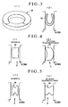
- Fig. 3 shows an annular metallic spring 12 which is a heat conducting member not forming part of the present invention
- Fig. 3(1) being a perspective view thereof and Fig. 3(2) being a sectional view thereof.
- the metallic spring 12 is capable of thermal contact at a predetermined pressing force with both the fuel injection valve 3 and the valve installation hole 2 (cylinder head 1), and is also easy to remove and install.
- Fig. 4 shows a temperature-sensing ring 13 which is a heat conducting member not forming part of the present invention
- Fig. 4(1) being a sectional view thereof in a normal condition (at low temperature)
- Fig. 4(2) being a sectional view thereof at high temperature.
- the temperature-sensing ring 13 is constituted by a bimetal, a shape memory alloy, or similar. At times such as the installation or removal of the fuel injection valve 3 and temperature-sensing ring 13 to or from the valve installation hole 2, the temperature-sensing ring 13 does not contact either the fuel injection valve 3 (nozzle portion 3B) or the valve installation hole 2, as shown in Fig. 4(1) , and thus can be easily installed in and removed from the annular space 11 therebetween.
- the temperature-sensing ring 13 changes shape as shown in Fig. 4(2) , thus enabling thermal conduction and heat discharge.
- thermal conduction efficiency can be further improved by ensuring that the temperature-sensing ring 13 changes shape such that the number of contact points and contact surfaces with the valve installation hole 2 and fuel injection valve 3 increases.
- Fig. 5 shows an expanding ring 14 Which is a heat conducting member not forming part of the present invention
- Fig. 5(1) being a sectional view thereof in a normal condition (at low temperature)
- Fig. 5(2) being a sectional view thereof at high temperature.
- the expanding ring 14 uses a material having a high coefficient of thermal expansion in order to utilize the expansion and contraction of the medium.
- the expanding ring 14 contracts at times such as the installation or removal of the fuel injection valve 3 and expanding ring 14 to or from the valve installation hole 2, and therefore does not contact either the fuel injection valve 3 or valve installation hole 2.
- the expanding ring 14 i can be easily installed in and removed from the annular space 11 therebetween.
- the expanding ring 14 expands so as to contact the valve installation hole 2 and fuel injection valve 3, thus enabling heat transfer.
- the combustion gas seal 6 is provided between the valve installation hole 2 and nozzle portion 3B, and the copper ring 8 is positioned on the side that is further from the tip end 3C (injection hole 7) of the nozzle portion 3B than the combustion gas seal 6.
- the copper ring 8 may be positioned on the side that is closer to the tip end 3C of the nozzle portion 3B than the combustion gas seal 6.
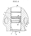
- Fig. 6 is a partially cut-away enlarged sectional view of a cooling structure 20 according to a second embodiment.
- the cooling structure 20 contrary to the cooling structure 4 ( Figs. 1 , 2 ) according to the first embodiment, the copper ring 8 and cooling water passage 9 are positioned further toward the combustion chamber 5 side than the combustion gas seal 6.
- the heat of the nozzle portion 3B (injection hole 7) of the fuel injection valve 3 is transmitted efficiently to the cooling water 10 inside the cooling water passage 9 of the cylinder head 1, and thus the generation of carbon deposits in the vicinity of the injection hole 7 can be suppressed.
- the nozzle portion of the fuel injection valve can be cooled efficiently, and the generation of carbon deposits in the vicinity of the injection hole can be suppressed.
Landscapes
- Engineering & Computer Science (AREA)
- Chemical & Material Sciences (AREA)
- Combustion & Propulsion (AREA)
- Mechanical Engineering (AREA)
- General Engineering & Computer Science (AREA)
- Fuel-Injection Apparatus (AREA)
Claims (8)
- Culasse de cylindre (1) comprenant une structure de refroidissement (4, 20) et une soupape d'injection de carburant (3) installée dans un orifice d'installation de soupape (2) par l'intermédiaire d'un élément d'étanchéité (6) et injectant du carburant dans une chambre de combustion (5), dans laquelle un élément de conduction thermique (8) est prévu sur une partie périphérique extérieure de ladite soupape d'injection de carburant (3) pour réaliser une conduction thermique entre une partie d'injecteur (3B) de ladite soupape d'injection de carburant (3) et ladite culasse de cylindre (1), et
ledit élément de conduction thermique (8) et un passage d'eau de refroidissement (9) prévus dans ladite culasse de cylindre (1) sont agencés l'un à côté de l'autre et séparés l'un de l'autre par une partie à basse température de ladite culasse de cylindre (1), moyennant quoi
ledit élément de conduction thermique (8) est un élément sensiblement cylindrique possédant un diamètre plus important sur un côté d'extrémité que sur l'autre côté d'extrémité, caractérisée en ce qu'une surface périphérique extérieure de ladite partie de diamètre plus important (8A) entre en contact avec une surface de paroi intérieure dudit orifice d'installation de soupape (2), et une surface périphérique intérieure de ladite partie de faible diamètre (8B) entre en contact avec ladite surface périphérique extérieure de ladite partie d'injecteur (3B), dans laquelle une surface périphérique intérieure de ladite partie de diamètre plus important (8A) est sans contact par rapport à ladite surface périphérique extérieure de ladite partie d'injecteur (3B) et une surface périphérique extérieure de ladite partie de faible diamètre (8B) est sans contact par rapport à ladite surface de paroi intérieure dudit orifice d'installation de soupape (2). - Culasse de cylindre (1) selon la revendication 1, caractérisée en ce que ladite partie à basse température de ladite culasse de cylindre (1) est une partie de paroi de celle-ci étant en contact direct avec ledit passage d'eau de refroidissement (9).
- Culasse de cylindre (1) selon la revendication 1 ou 2, caractérisée en ce que ledit élément de conduction thermique (8) est espacé de ladite partie périphérique extérieure de ladite soupape d'injection de carburant (3) et ladite surface de paroi intérieure dudit orifice d'installation de soupape (2) à basses températures, et configuré pour entrer en contact avec ladite partie périphérique extérieure et ladite surface de paroi intérieure à hautes températures.
- Culasse de cylindre (1) selon la revendication 1 ou 2, caractérisée en ce que ledit élément d'étanchéité (6) est prévu pour étanchéifier un gaz de combustion par rapport à ladite chambre de combustion (5),
ladite partie d'injecteur (38) de ladite soupape d'injection de carburant (3) et ledit orifice d'installation de soupape (2) de ladite culasse de cylindre (1) sont cylindriques, et
ladite soupape d'injection de carburant (3) est fixée en position en insérant ladite partie d'injecteur (3B) et ledit élément d'étanchéité (6) dans ledit orifice d'installation de soupape (2) pour injecter du carburant dans ladite chambre de combustion (5) à partir d'un orifice d'injection (7) prévu sur une extrémité de pointe (3C) de ladite partie d'injecteur (3B),
dans laquelle ledit élément de conduction thermique (8) est installé dans un espace annulaire (11) formé entre ladite surface de paroi intérieure dudit orifice d'installation de soupape (2) et ladite surface périphérique extérieure de ladite partie d'injecteur (3B) afin d'entrer en contact avec ladite surface de paroi intérieure et ladite surface périphérique extérieure. - Culasse de cylindre (1) selon la revendication 4, caractérisée en ce que ledit élément de conduction thermique (8) comprend une conductivité thermique supérieure à celle dudit élément d'étanchéité (6).
- Culasse de cylindre (1) selon la revendication 5, caractérisée en ce que ledit élément de conduction thermique (8) est constitué par un matériau de cuivre.
- Culasse de cylindre (1) selon les revendications 4 à 6, caractérisée en ce que ledit élément d'étanchéité (6) est prévu entre ledit orifice d'installation de soupape (2) et ladite partie d'injecteur (3B), et ledit élément de conduction thermique (8) est positionné sur le côté qui est plus éloigné d'une extrémité de pointe de ladite partie d'injecteur (3B) que ledit élément d'étanchéité (6).
- Culasse de cylindre (1) selon les revendications 4 à 6, caractérisée en ce que ledit élément d'étanchéité (6) est prévu entre ledit orifice d'installation de soupape (2) et ladite partie d'injecteur (38), et ledit élément de conduction thermique (8) est positionné sur le côté qui est plus près d'une extrémité de pointe de ladite partie d'injecteur (3B) que ledit élément d'étanchéité (6).
Applications Claiming Priority (2)
| Application Number | Priority Date | Filing Date | Title |
|---|---|---|---|
| JP2003061856 | 2003-03-07 | ||
| JP2003061856A JP4081716B2 (ja) | 2003-03-07 | 2003-03-07 | 燃料噴射弁の冷却構造 |
Publications (3)
| Publication Number | Publication Date |
|---|---|
| EP1455083A2 EP1455083A2 (fr) | 2004-09-08 |
| EP1455083A3 EP1455083A3 (fr) | 2005-10-19 |
| EP1455083B1 true EP1455083B1 (fr) | 2008-09-03 |
Family
ID=32821241
Family Applications (1)
| Application Number | Title | Priority Date | Filing Date |
|---|---|---|---|
| EP20040003676 Expired - Lifetime EP1455083B1 (fr) | 2003-03-07 | 2004-02-18 | Structure de refroidissement pour injecteur de carburant |
Country Status (3)
| Country | Link |
|---|---|
| EP (1) | EP1455083B1 (fr) |
| JP (1) | JP4081716B2 (fr) |
| DE (1) | DE602004016235D1 (fr) |
Families Citing this family (5)
| Publication number | Priority date | Publication date | Assignee | Title |
|---|---|---|---|---|
| DE102004048395B4 (de) * | 2004-10-05 | 2015-12-10 | Continental Automotive Gmbh | Piezo-Einspritzventil mit Kontaktelementen zur Wärmeableitung |
| DE102005006641A1 (de) * | 2005-02-14 | 2006-08-24 | Siemens Ag | Einspritzventil zum Einspritzen von Kraftstoff und Zylinderkopf |
| JP2010138778A (ja) * | 2008-12-11 | 2010-06-24 | Mitsubishi Heavy Ind Ltd | 燃料噴射弁の冷却構造 |
| JP2011064124A (ja) * | 2009-09-17 | 2011-03-31 | Hitachi Automotive Systems Ltd | 燃料噴射弁 |
| GB2619536B (en) * | 2022-06-09 | 2024-07-17 | Phinia Delphi Luxembourg Sarl | Fuel injector for direct injection of gaseous fuel |
Family Cites Families (4)
| Publication number | Priority date | Publication date | Assignee | Title |
|---|---|---|---|---|
| US2175450A (en) * | 1935-08-28 | 1939-10-10 | Atlas Diesel Ab | Internal combustion engine |
| JPH1089192A (ja) * | 1996-09-10 | 1998-04-07 | Toyota Central Res & Dev Lab Inc | デポジット低減式燃料噴射弁 |
| DE19808068A1 (de) * | 1998-02-26 | 1999-09-02 | Bosch Gmbh Robert | Brennstoffeinspritzventil |
| JP2001221123A (ja) * | 2000-02-07 | 2001-08-17 | Nissan Diesel Motor Co Ltd | 燃料噴射ノズルの冷却構造 |
-
2003
- 2003-03-07 JP JP2003061856A patent/JP4081716B2/ja not_active Expired - Fee Related
-
2004
- 2004-02-18 DE DE200460016235 patent/DE602004016235D1/de not_active Expired - Lifetime
- 2004-02-18 EP EP20040003676 patent/EP1455083B1/fr not_active Expired - Lifetime
Also Published As
| Publication number | Publication date |
|---|---|
| DE602004016235D1 (de) | 2008-10-16 |
| EP1455083A3 (fr) | 2005-10-19 |
| JP4081716B2 (ja) | 2008-04-30 |
| JP2004270529A (ja) | 2004-09-30 |
| EP1455083A2 (fr) | 2004-09-08 |
Similar Documents
| Publication | Publication Date | Title |
|---|---|---|
| JP4308923B2 (ja) | 燃料噴射弁 | |
| JP2005256661A (ja) | シリンダブロックの冷却構造 | |
| JPH05164482A (ja) | 液化天然ガスの気化装置 | |
| JP6756299B2 (ja) | スパークプラグスリーブ | |
| JP2006220409A (ja) | 熱遮蔽 | |
| EP1455083B1 (fr) | Structure de refroidissement pour injecteur de carburant | |
| US7556011B2 (en) | Valve structure for internal combustion | |
| JP4841619B2 (ja) | 開口するチャンバを備えたマルチスパークプラグ | |
| JP5717990B2 (ja) | 分解ガスの冷却のための熱交換器 | |
| US1727621A (en) | Exhaust valve | |
| WO2001033066A1 (fr) | Structure d'orifice d'echappement d'un moteur a combustion interne | |
| CN100412423C (zh) | 垫片 | |
| JP4710944B2 (ja) | 燃料噴射弁 | |
| JP4616962B2 (ja) | シール装置 | |
| JPH0486368A (ja) | ディーゼルエンジンの燃料噴射ノズルのノズル先端部防熱装置 | |
| CN101779034B (zh) | 燃料喷射阀装置 | |
| US6990805B2 (en) | Waste heat recovery device for internal combustion engine | |
| CN214046103U (zh) | 等离子体发生器阴极 | |
| KR200388114Y1 (ko) | 핀-휜이 설치된 충돌제트/유출냉각장치 | |
| JP7126475B2 (ja) | サーモアクチュエータ | |
| CN111623233B (zh) | 固体氢存储装置 | |
| JP6250366B2 (ja) | 内燃機関の燃料噴射弁温度抑制機構およびこれを備えた内燃機関 | |
| JP4285621B2 (ja) | 燃料噴射弁の取付部構造 | |
| JP5207309B2 (ja) | スパークプラグ | |
| JP3837583B2 (ja) | 流動層ボイラの伝熱管カバー構造 |
Legal Events
| Date | Code | Title | Description |
|---|---|---|---|
| PUAI | Public reference made under article 153(3) epc to a published international application that has entered the european phase |
Free format text: ORIGINAL CODE: 0009012 |
|
| 17P | Request for examination filed |
Effective date: 20040218 |
|
| AK | Designated contracting states |
Kind code of ref document: A2 Designated state(s): AT BE BG CH CY CZ DE DK EE ES FI FR GB GR HU IE IT LI LU MC NL PT RO SE SI SK TR |
|
| AX | Request for extension of the european patent |
Extension state: AL LT LV MK |
|
| PUAL | Search report despatched |
Free format text: ORIGINAL CODE: 0009013 |
|
| AK | Designated contracting states |
Kind code of ref document: A3 Designated state(s): AT BE BG CH CY CZ DE DK EE ES FI FR GB GR HU IE IT LI LU MC NL PT RO SE SI SK TR |
|
| AX | Request for extension of the european patent |
Extension state: AL LT LV MK |
|
| RAP1 | Party data changed (applicant data changed or rights of an application transferred) |
Owner name: BOSCH CORPORATION Owner name: NISSAN MOTOR COMPANY, LIMITED |
|
| AKX | Designation fees paid |
Designated state(s): DE FR GB |
|
| 17Q | First examination report despatched |
Effective date: 20060220 |
|
| 17Q | First examination report despatched |
Effective date: 20060220 |
|
| GRAP | Despatch of communication of intention to grant a patent |
Free format text: ORIGINAL CODE: EPIDOSNIGR1 |
|
| GRAS | Grant fee paid |
Free format text: ORIGINAL CODE: EPIDOSNIGR3 |
|
| GRAA | (expected) grant |
Free format text: ORIGINAL CODE: 0009210 |
|
| AK | Designated contracting states |
Kind code of ref document: B1 Designated state(s): DE FR GB |
|
| REG | Reference to a national code |
Ref country code: GB Ref legal event code: FG4D |
|
| REF | Corresponds to: |
Ref document number: 602004016235 Country of ref document: DE Date of ref document: 20081016 Kind code of ref document: P |
|
| PLBE | No opposition filed within time limit |
Free format text: ORIGINAL CODE: 0009261 |
|
| STAA | Information on the status of an ep patent application or granted ep patent |
Free format text: STATUS: NO OPPOSITION FILED WITHIN TIME LIMIT |
|
| 26N | No opposition filed |
Effective date: 20090604 |
|
| PGFP | Annual fee paid to national office [announced via postgrant information from national office to epo] |
Ref country code: DE Payment date: 20130426 Year of fee payment: 10 |
|
| PGFP | Annual fee paid to national office [announced via postgrant information from national office to epo] |
Ref country code: FR Payment date: 20140218 Year of fee payment: 11 |
|
| PGFP | Annual fee paid to national office [announced via postgrant information from national office to epo] |
Ref country code: GB Payment date: 20140220 Year of fee payment: 11 |
|
| REG | Reference to a national code |
Ref country code: DE Ref legal event code: R119 Ref document number: 602004016235 Country of ref document: DE |
|
| REG | Reference to a national code |
Ref country code: DE Ref legal event code: R119 Ref document number: 602004016235 Country of ref document: DE Effective date: 20140902 |
|
| PG25 | Lapsed in a contracting state [announced via postgrant information from national office to epo] |
Ref country code: DE Free format text: LAPSE BECAUSE OF NON-PAYMENT OF DUE FEES Effective date: 20140902 |
|
| GBPC | Gb: european patent ceased through non-payment of renewal fee |
Effective date: 20150218 |
|
| REG | Reference to a national code |
Ref country code: FR Ref legal event code: ST Effective date: 20151030 |
|
| PG25 | Lapsed in a contracting state [announced via postgrant information from national office to epo] |
Ref country code: GB Free format text: LAPSE BECAUSE OF NON-PAYMENT OF DUE FEES Effective date: 20150218 |
|
| PG25 | Lapsed in a contracting state [announced via postgrant information from national office to epo] |
Ref country code: FR Free format text: LAPSE BECAUSE OF NON-PAYMENT OF DUE FEES Effective date: 20150302 |