EP1455083B1 - Cooling structure for fuel injection valve - Google Patents
Cooling structure for fuel injection valve Download PDFInfo
- Publication number
- EP1455083B1 EP1455083B1 EP20040003676 EP04003676A EP1455083B1 EP 1455083 B1 EP1455083 B1 EP 1455083B1 EP 20040003676 EP20040003676 EP 20040003676 EP 04003676 A EP04003676 A EP 04003676A EP 1455083 B1 EP1455083 B1 EP 1455083B1
- Authority
- EP
- European Patent Office
- Prior art keywords
- cylinder head
- nozzle portion
- fuel injection
- installation hole
- heat conducting
- Prior art date
- Legal status (The legal status is an assumption and is not a legal conclusion. Google has not performed a legal analysis and makes no representation as to the accuracy of the status listed.)
- Expired - Fee Related
Links
Images


Classifications
-
- F—MECHANICAL ENGINEERING; LIGHTING; HEATING; WEAPONS; BLASTING
- F02—COMBUSTION ENGINES; HOT-GAS OR COMBUSTION-PRODUCT ENGINE PLANTS
- F02M—SUPPLYING COMBUSTION ENGINES IN GENERAL WITH COMBUSTIBLE MIXTURES OR CONSTITUENTS THEREOF
- F02M61/00—Fuel-injectors not provided for in groups F02M39/00 - F02M57/00 or F02M67/00
- F02M61/14—Arrangements of injectors with respect to engines; Mounting of injectors
-
- F—MECHANICAL ENGINEERING; LIGHTING; HEATING; WEAPONS; BLASTING
- F02—COMBUSTION ENGINES; HOT-GAS OR COMBUSTION-PRODUCT ENGINE PLANTS
- F02M—SUPPLYING COMBUSTION ENGINES IN GENERAL WITH COMBUSTIBLE MIXTURES OR CONSTITUENTS THEREOF
- F02M53/00—Fuel-injection apparatus characterised by having heating, cooling or thermally-insulating means
- F02M53/04—Injectors with heating, cooling, or thermally-insulating means
Description
- The present invention relates to a cylinder head having a cooling structure for a fuel injection valve according to the preamble part of
independent claim 1. - From
JP 2001 221123A - Conventionally, a fuel injection valve for injecting fuel directly into a combustion chamber is installed through insertion into a valve installation hole in a cylinder head, and is sealed by a sealing member provided on the outer peripheral portion thereof such that combustion gas from the combustion chamber does not leak outside.
- Meanwhile, heat from the combustion chamber causes the temperature of a nozzle portion positioned on the tip end side of the fuel injection valve and facing the combustion chamber to rise, whereby the small amount of residual fuel attached to an injection hole at the tip end of the nozzle portion is carbonized to produce a carbon deposit. Accumulation of this carbon deposit in the vicinity of the injection hole has an adverse effect on the injection characteristic and the injection amount.
- However, the aforementioned sealing member typically has a low thermal conductivity, and since the sealing member is installed in the valve installation hole between the fuel injection valve and cylinder head with a predetermined pressing force, a problem arises in that the heat of the nozzle portion on the fuel injection valve cannot easily be conducted outside of the cylinder head through the sealing member.
- In other words, to prevent the generation of carbon deposits on the injection hole, the heat of the nozzle portion of the fuel injection valve, which is caused to increase in temperature by combustion heat from the combustion chamber, must be discharged outside efficiently, but at present, a cooling structure with an adequate heat-discharging function has not yet been developed.
-
JP 2001-132582 JP-2002-138924 - The present invention has been designed in consideration of the problems described above, and it is an objective thereof to improve a cylinder head having a cooling structure according to the preamble portion of
independent claim 1 so as to enable an exact positioning of the fuel injection valve within the valve installation hole and a secure and exact heat conduction from the fuel injection valve to the cylinder head. - The objective is solved according to the present invention by a cylinder head comprising a cooling structure for a fuel injection valve being installed in a valve installation hole via a sealing member and injecting fuel into a combustion chamber, wherein a heat conducting member is provided on an outer peripheral portion of said fuel injection valve for performing thermal conduction between a nozzle portion of said fuel injection valve and said cylinder head, and said heat conducting member and a cooling water passage provided in said cylinder head are arranged adjacent to each other and separated from each other by a low temperature portion of said cylinder head, wherein said heat conducting member is a substantially cylindrical member having a larger diameter on one end side than on the other end side, whereby an outer peripheral surface of said larger diameter part contacts an inner wall surface of said valve installation hole, and an inner peripheral surface of said small diameter part contacts said outer peripheral surface of said nozzle portion, wherein an inner peripheral surface of said larger diameter part is contactless to said outer peripheral surface of said nozzle portion and an outer peripheral surface of said small diameter part is contactless to said inner wall surface of said valve installation hole.
- It is an advantage that an actively releasing the heat of the nozzle portion of the fuel injection valve to a low temperature portion of the cylinder head could be obtained.
- The aforementioned low temperature portion may be a cooling water passage provided in the cylinder head.
- Preferably, said sealing member is provided for sealing a combustion gas from said combustion chamber , said nozzle portion of said fuel injection valve and said valve installation hole of said cylinder head are cylindrical, and said fuel injection valve is fixed in position by inserting said nozzle portion and said sealing member into said valve installation hole to inject fuel into said combustion chamber from an injection hole provided on a tip end of said nozzle portion, wherein said heat conducting member is installed in an annular space formed between said inner wall surface of said valve installation hole and said outer peripheral surface of said nozzle portion so as to contact both said inner wall surface and said outer peripheral surface.
- The heat conducting member may have a greater thermal conductivity than the sealing member.
- The heat conducting member may be constituted by a copper material.
- The heat conducting member is a substantially cylindrical member having a larger diameter on one end side than on the other end side. An outer peripheral surface of the large diameter part is capable of contacting the inner wall surface of the valve installation hole, and an inner peripheral surface of the small diameter part is capable of contacting the outer peripheral surface of the nozzle portion.
- The sealing member is provided between the valve installation hole and nozzle portion, and the heat conducting member may be positioned on the side that is further from the tip end of the nozzle portion than the sealing member.
- The sealing member is provided between the valve installation hole and the nozzle portion, and the heat conducting member may be positioned on the side that is closer to the tip end of the nozzle portion than the sealing member.
- Furthermore, the heat conducting member is provided for performing thermal conduction between a high temperature portion in the vicinity of the injection hole in the nozzle portion, which is the tip end portion of the fuel injection valve, and a low temperature portion in the cylinder head, and hence even when the sealing member is interposed between the fuel injection valve and the cylinder head, the high temperature of the nozzle portion of the fuel injection valve can be actively released to the low temperature portion of the cylinder head. Thus the temperature of the nozzle portion, particularly in the vicinity of the injection hole, decreases such that carbon deposits can be reduced.
- Cooling efficiency can be raised particularly when the heat conducting member is provided in the vicinity of the cooling water passage in the cylinder head.
- Further, when the heat conducting member is constituted by a material having a greater thermal conductivity than the sealing member, for example a copper material or the like, an even more efficient thermal conduction performance can be ensured.
- Further preferred embodiments are subject of further dependent claims.
- In the following, the present invention is explained in greater detail by means of several embodiments thereof in conjunction with the accompanying drawings, wherein:
-
Fig. 1 is a sectional view of afuel injection valve 3 part comprising acooling structure 4 according to a first embodiment and installed in avalve installation hole 2 of acylinder head 1; -
Fig. 2 is a partially cut-away enlarged sectional view showing thecooling structure 4 in anozzle portion 3B part of same; -
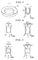
Fig. 3 shows an annularmetallic spring 12 which is a heat conducting member not forming part of the present invention, -
Fig. 3(1) being a perspective view thereof, andFig. 3(2) being a sectional view thereof; -
Fig. 4 shows a temperature-sensingring 13 which is a heat conducting member not forming part of the present invention, -
Fig. 4(1) being a sectional view thereof in a normal condition (at low temperature), andFig. 4(2) being a sectional view thereof at high temperature; -
Fig. 5 shows an expandingring 14 which is a heat conducting member not forming part of the present invention, -
Fig. 5(1) being a sectional view thereof in a normal condition (at low temperature), andFig. 5(2) being a sectional view thereof at high temperature; and -
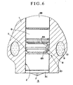
Fig. 6 is a partially cut-away enlarged sectional view of acooling structure 20 for a fuel injection valve according to a second embodiment. - A cooling structure for a fuel injection valve according to a first embodiment will now be described on the basis of
Figs. 1 and2 . -
Fig. 1 is a sectional view of afuel injection valve 3 part installed in avalve installation hole 2 of acylinder head 1. Thefuel injection valve 3 comprises amain body portion 3A, and acylindrical nozzle portion 3B which is the tip end portion of themain body portion 3A and has a smaller diameter than themain body portion 3A. - A
cooling structure 4 for thefuel injection valve 3 according to the present teaching is provided on thenozzle portion 3B part. -
Fig. 2 is a partially cut-away enlarged sectional view of thenozzle portion 3B part of thefuel injection valve 3, and shows thecooling structure 4 of thefuel injection valve 3. - A combustion gas seal 6 (sealing member) of an arbitrary constitution is provided on a
combustion chamber 5 side between thevalve installation hole 2 and thenozzle portion 3B of thefuel injection valve 3. - The
fuel injection valve 3 injects fuel into thecombustion chamber 5 from aninjection hole 7 in atip end 3C of thenozzle portion 3B. - The
cooling structure 4 comprises an annular copper ring 8 (heat conducting member), acooling water passage 9, and coolingwater 10 inside thecooling water passage 9. - The
copper ring 8 is positioned in the cylindricalvalve installation hole 2 outside of thecombustion gas seal 6 on the opposite side to thecombustion chamber 5, and contacts both an outer peripheral surface of the fuel injection valve 3 (nozzle portion 3B) and an inner wall surface of thevalve installation hole 2. - More specifically, the
copper ring 8 is a substantially cylindrical member in which the diameter of the end side thereof (large diameter part 8A) that is furthest from thetip end 3C of thenozzle portion 3B is larger than the diameter of the other end side thereof (small diameter part 8B) that is near to thetip end 3C of thenozzle portion 3B. In anannular space 11 formed between the inner wall surface of thevalve installation hole 2 and the outer peripheral surface of thenozzle portion 3B, the outer peripheral surface of thelarge diameter part 8A contacts the inner wall surface of thevalve installation hole 2, and the inner peripheral surface of thesmall diameter part 8B contacts the outer peripheral surface of thenozzle portion 3B. - In the
cooling structure 4 constituted in this manner, thecombustion gas seal 6 seals in combustion gas from thecombustion chamber 5, and thecopper ring 8 conducts high temperatures from the vicinity of theinjection hole 7 in thenozzle portion 3B of thefuel injection valve 3 to thecylinder head 1 and thecooling water 10 inside thecooling water passage 9. - Since the
copper ring 8 andcooling water passage 9 are positioned adjacent to each other via the wall surface of thecylinder head 1, heat from the vicinity of theinjection hole 7 can be actively conducted to thecylinder head 1 from thefuel injection valve 3 and discharged efficiently even though thecombustion gas seal 6 is positioned therebetween. In particular, by cooling the vicinity of theinjection valve 7, the generation of carbon deposits can be suppressed. - In particular, by providing a constitution in which the
small diameter part 8B of thecopper ring 8 is disposed in theannular space 11 formed between the inner wall surface of thevalve installation hole 2 and the outer peripheral surface of thenozzle portion 3B facing thetip end 3C of thenozzle portion 3B, the heat conducting path from thenozzle portion 3B to thecylinder head 1 can be formed in the vicinity of thetip end 3C of thenozzle portion 3B, and thus the heat that is transmitted to thefuel injection valve 3 can be released to thecylinder head 1 efficiently. - The
combustion gas seal 6 also contacts both the inner wall surface of thevalve installation hole 2 and the outer peripheral surface of thenozzle portion 3B, and although thermal conduction is also possible through thecombustion gas seal 6, the constitution and material of thecombustion gas seal 6 should be determined such that a good sealing property can be ensured. As a result, it is difficult to generate a high degree of thermal conductivity in thecombustion gas seal 6. On the other hand, the material for thecopper ring 8 may be selected with a comparative amount of freedom, and hence thecopper ring 8 may be constituted by a material (a copper material, for example) having a higher degree of thermal conductivity than the material constituting thecombustion gas seal 6, thereby ensuring a more efficient thermal conduction performance. - A desired structure other than the
copper ring 8 may be employed as the heat conducting member of the present invention. - For example,
Fig. 3 shows an annularmetallic spring 12 which is a heat conducting member not forming part of the present invention, -
Fig. 3(1) being a perspective view thereof andFig. 3(2) being a sectional view thereof. - Due to its resilience, the
metallic spring 12 is capable of thermal contact at a predetermined pressing force with both thefuel injection valve 3 and the valve installation hole 2 (cylinder head 1), and is also easy to remove and install. -
Fig. 4 shows a temperature-sensingring 13 which is a heat conducting member not forming part of the present invention, -
Fig. 4(1) being a sectional view thereof in a normal condition (at low temperature) , andFig. 4(2) being a sectional view thereof at high temperature. - The temperature-
sensing ring 13 is constituted by a bimetal, a shape memory alloy, or similar. At times such as the installation or removal of thefuel injection valve 3 and temperature-sensing ring 13 to or from thevalve installation hole 2, the temperature-sensing ring 13 does not contact either the fuel injection valve 3 (nozzle portion 3B) or thevalve installation hole 2, as shown inFig. 4(1) , and thus can be easily installed in and removed from theannular space 11 therebetween. - Further, only at high temperatures when the temperature of the
fuel injection valve 3 must be reduced, the temperature-sensingring 13 changes shape as shown inFig. 4(2) , thus enabling thermal conduction and heat discharge. - As shown in
Fig. 4(2) in particular, when the temperature-sensing ring 13 changes shape at high temperatures, thermal conduction efficiency can be further improved by ensuring that the temperature-sensingring 13 changes shape such that the number of contact points and contact surfaces with thevalve installation hole 2 andfuel injection valve 3 increases. -
Fig. 5 shows an expandingring 14 Which is a heat conducting member not forming part of the present invention, -
Fig. 5(1) being a sectional view thereof in a normal condition (at low temperature), andFig. 5(2) being a sectional view thereof at high temperature. - The expanding
ring 14 uses a material having a high coefficient of thermal expansion in order to utilize the expansion and contraction of the medium. - As shown in
Fig. 5(1) , the expandingring 14 contracts at times such as the installation or removal of thefuel injection valve 3 and expandingring 14 to or from thevalve installation hole 2, and therefore does not contact either thefuel injection valve 3 orvalve installation hole 2. Hence the expandingring 14i can be easily installed in and removed from theannular space 11 therebetween. - As shown in
Fig. 5(2) , at high temperatures, the expandingring 14 expands so as to contact thevalve installation hole 2 andfuel injection valve 3, thus enabling heat transfer. - Note that in the first embodiment shown in
Figs. 1 and2 , thecombustion gas seal 6 is provided between thevalve installation hole 2 andnozzle portion 3B, and thecopper ring 8 is positioned on the side that is further from the tip end 3C (injection hole 7) of thenozzle portion 3B than thecombustion gas seal 6. However, thecopper ring 8 may be positioned on the side that is closer to thetip end 3C of thenozzle portion 3B than thecombustion gas seal 6. - More specifically,
Fig. 6 is a partially cut-away enlarged sectional view of acooling structure 20 according to a second embodiment. In thecooling structure 20, contrary to the cooling structure 4 (Figs. 1 ,2 ) according to the first embodiment, thecopper ring 8 andcooling water passage 9 are positioned further toward thecombustion chamber 5 side than thecombustion gas seal 6. - Similarly to the
cooling structure 4 inFigs. 1 and2 , in thecooling structure 20 constituted in this manner, the heat of thenozzle portion 3B (injection hole 7) of thefuel injection valve 3 is transmitted efficiently to the coolingwater 10 inside the coolingwater passage 9 of thecylinder head 1, and thus the generation of carbon deposits in the vicinity of theinjection hole 7 can be suppressed. - According to the present teaching as described above, by providing a heat conducting member between the valve installation hole of a cylinder head and the nozzle portion of a fuel injection valve such that heat is actively discharged to the cylinder head side, the nozzle portion of the fuel injection valve can be cooled efficiently, and the generation of carbon deposits in the vicinity of the injection hole can be suppressed.
Claims (8)
- A cylinder head (1) comprising a cooling structure (4, 20) and a fuel injection valve (3) installed in a valve installation hole (2) via a sealing member (6) and injecting fuel into a combustion chamber (5), wherein a heat conducting member (8) is provided on an outer peripheral portion of said fuel injection valve (3) for performing thermal conduction between a nozzle portion (38) of said fuel injection valve(3) and said cylinder head (1), and
said heat conducting member (8) and a cooling water passage (9) provided in said cylinder head (1) are arranged adjacent to each other and separated from each other by a low temperature portion of said cylinder head (1), whereby
said heat conducting member (8) is a substantially cylindrical member having a larger diameter on one end side than on the other end side, characterized in that an outer peripheral surface of said larger diameter part (8A) contacts an inner wall surface of said valve installation hole (2), and an inner peripheral surface of said small diameter part (8B) contacts said outer peripheral surface of said nozzle portion (3B), wherein an inner peripheral surface of said larger diameter part (8A) is contactless to said outer peripheral surface of said nozzle portion (38) and an outer peripheral surface of said small diameter part (8B) is contactless to said inner wall surface of said valve installation hole (2). - A cylinder head (1) according claim 1, characterized in that said low temperature portion of said cylinder head (1) is a wall portion thereof being direct in contact with said cooling water passage (9).
- A cylinder head (1) according claim 1 or 2, characterized in that said heat conducting member (8) is spaced from said outer peripheral portion of said fuel injection valve (3) and said inner wall surface of said valve installation hole(2) at low temperatures, and configured to contact said outer peripheral portion and said inner wall surface at high temperatures.
- A cylinder head (1) according to claim 1 or 2, characterized in that said sealing member (6) is provided for sealing a combustion gas from said combustion chamber (5),
said nozzle portion (3B) of said fuel injection valve (3) and said valve installation hole (2) of said cylinder head (1) are cylindrical, and
said fuel injection valve (3) is fixed in position by inserting said nozzle portion (3B) and
said sealing member (6) into said valve installation hole (2) to inject fuel into said combustion chamber (5) from an injection hole (7) provided on a tip end (3C) of said nozzle portion (3B),
wherein said heat conducting member (8) is installed in an annular space (11) formed between said inner wall surface of said valve installation hole (2) and said outer peripheral surface of said nozzle portion (3B) so as to contact both said inner wall surface and said outer peripheral surface. - A cylinder head (1) according to claim 4, characterized in that said heat conducting member (8) comprises a greater thermal conductivity than said sealing member (6).
- A cylinder head (1) according to claim 5, characterized in that said heat conducting member (8) is constituted by a copper material.
- A cylinder head (1) according to claims 4 to 6, characterized in that said sealing member (6) is provided between said valve installation hole (2) and said nozzle portion (3B), and said heat conducting member (8) is positioned on the side that is farther from a tip end of said nozzle portion (3B) than said sealing member (6).
- A cylinder head (1) according to claims 4 to 6, characterized in that said sealing member (6) is provided between said valve installation hole (2) and said nozzle portion (38), and said heat conducting member (8) is positioned on the side that is closer to a tip end of said nozzle portion (3B) than said sealing member (6).
Applications Claiming Priority (2)
| Application Number | Priority Date | Filing Date | Title |
|---|---|---|---|
| JP2003061856A JP4081716B2 (en) | 2003-03-07 | 2003-03-07 | Fuel injection valve cooling structure |
| JP2003061856 | 2003-03-07 |
Publications (3)
| Publication Number | Publication Date |
|---|---|
| EP1455083A2 EP1455083A2 (en) | 2004-09-08 |
| EP1455083A3 EP1455083A3 (en) | 2005-10-19 |
| EP1455083B1 true EP1455083B1 (en) | 2008-09-03 |
Family
ID=32821241
Family Applications (1)
| Application Number | Title | Priority Date | Filing Date |
|---|---|---|---|
| EP20040003676 Expired - Fee Related EP1455083B1 (en) | 2003-03-07 | 2004-02-18 | Cooling structure for fuel injection valve |
Country Status (3)
| Country | Link |
|---|---|
| EP (1) | EP1455083B1 (en) |
| JP (1) | JP4081716B2 (en) |
| DE (1) | DE602004016235D1 (en) |
Families Citing this family (5)
| Publication number | Priority date | Publication date | Assignee | Title |
|---|---|---|---|---|
| DE102004048395B4 (en) * | 2004-10-05 | 2015-12-10 | Continental Automotive Gmbh | Piezo injector with contact elements for heat dissipation |
| DE102005006641A1 (en) * | 2005-02-14 | 2006-08-24 | Siemens Ag | Injection valve for injecting fuel and cylinder head |
| JP2010138778A (en) * | 2008-12-11 | 2010-06-24 | Mitsubishi Heavy Ind Ltd | Cooling structure of fuel injection valve |
| JP2011064124A (en) * | 2009-09-17 | 2011-03-31 | Hitachi Automotive Systems Ltd | Fuel injection valve |
| GB2619536A (en) * | 2022-06-09 | 2023-12-13 | Borgwarner Luxembourg Automotive Systems S A | Fuel injector for direct injection of gaseous fuel |
Family Cites Families (4)
| Publication number | Priority date | Publication date | Assignee | Title |
|---|---|---|---|---|
| US2175450A (en) * | 1935-08-28 | 1939-10-10 | Atlas Diesel Ab | Internal combustion engine |
| JPH1089192A (en) * | 1996-09-10 | 1998-04-07 | Toyota Central Res & Dev Lab Inc | Deposit reducing-type fuel injection valve |
| DE19808068A1 (en) * | 1998-02-26 | 1999-09-02 | Bosch Gmbh Robert | Fuel injector |
| JP2001221123A (en) * | 2000-02-07 | 2001-08-17 | Nissan Diesel Motor Co Ltd | Strut for cooling fuel injection nozzle |
-
2003
- 2003-03-07 JP JP2003061856A patent/JP4081716B2/en not_active Expired - Fee Related
-
2004
- 2004-02-18 DE DE200460016235 patent/DE602004016235D1/en not_active Expired - Lifetime
- 2004-02-18 EP EP20040003676 patent/EP1455083B1/en not_active Expired - Fee Related
Also Published As
| Publication number | Publication date |
|---|---|
| JP2004270529A (en) | 2004-09-30 |
| JP4081716B2 (en) | 2008-04-30 |
| EP1455083A3 (en) | 2005-10-19 |
| DE602004016235D1 (en) | 2008-10-16 |
| EP1455083A2 (en) | 2004-09-08 |
Similar Documents
| Publication | Publication Date | Title |
|---|---|---|
| JP4308923B2 (en) | Fuel injection valve | |
| JP4841619B2 (en) | Multi-spark plug with open chamber | |
| JP2005256661A (en) | Cooling structure of cylinder block | |
| JP6756299B2 (en) | Spark plug sleeve | |
| JP2006220409A (en) | Heat shielding | |
| EP1455083B1 (en) | Cooling structure for fuel injection valve | |
| US7556011B2 (en) | Valve structure for internal combustion | |
| JP2006037960A (en) | Fuel injection system | |
| US1727621A (en) | Exhaust valve | |
| JP5717990B2 (en) | Heat exchanger for cooling of cracked gas | |
| WO2001033066A1 (en) | Exhaust port structure of internal combustion engine | |
| CN102953863A (en) | Manifold gasket assembly | |
| JP4616962B2 (en) | Sealing device | |
| US6990805B2 (en) | Waste heat recovery device for internal combustion engine | |
| JP2009191672A (en) | Fuel injection valve device | |
| JP2001124890A (en) | Main steam relief safety valve | |
| KR200388114Y1 (en) | Apparatus for impingement/effusion cooling with pin-fin | |
| JP4021405B2 (en) | Fuel injection valve | |
| CN111623233B (en) | Solid hydrogen storage device | |
| JP6250366B2 (en) | Fuel injection valve temperature suppression mechanism for internal combustion engine and internal combustion engine provided with the same | |
| JP2007107456A (en) | Heat insulating sleeve for fuel injection valve | |
| JP5207309B2 (en) | Spark plug | |
| CN214046103U (en) | Plasma generator cathode | |
| JP3837583B2 (en) | Heat transfer tube cover structure of fluidized bed boiler | |
| JP4285621B2 (en) | Mounting structure of fuel injection valve |
Legal Events
| Date | Code | Title | Description |
|---|---|---|---|
| PUAI | Public reference made under article 153(3) epc to a published international application that has entered the european phase |
Free format text: ORIGINAL CODE: 0009012 |
|
| 17P | Request for examination filed |
Effective date: 20040218 |
|
| AK | Designated contracting states |
Kind code of ref document: A2 Designated state(s): AT BE BG CH CY CZ DE DK EE ES FI FR GB GR HU IE IT LI LU MC NL PT RO SE SI SK TR |
|
| AX | Request for extension of the european patent |
Extension state: AL LT LV MK |
|
| PUAL | Search report despatched |
Free format text: ORIGINAL CODE: 0009013 |
|
| AK | Designated contracting states |
Kind code of ref document: A3 Designated state(s): AT BE BG CH CY CZ DE DK EE ES FI FR GB GR HU IE IT LI LU MC NL PT RO SE SI SK TR |
|
| AX | Request for extension of the european patent |
Extension state: AL LT LV MK |
|
| RAP1 | Party data changed (applicant data changed or rights of an application transferred) |
Owner name: BOSCH CORPORATION Owner name: NISSAN MOTOR COMPANY, LIMITED |
|
| AKX | Designation fees paid |
Designated state(s): DE FR GB |
|
| 17Q | First examination report despatched |
Effective date: 20060220 |
|
| 17Q | First examination report despatched |
Effective date: 20060220 |
|
| GRAP | Despatch of communication of intention to grant a patent |
Free format text: ORIGINAL CODE: EPIDOSNIGR1 |
|
| GRAS | Grant fee paid |
Free format text: ORIGINAL CODE: EPIDOSNIGR3 |
|
| GRAA | (expected) grant |
Free format text: ORIGINAL CODE: 0009210 |
|
| AK | Designated contracting states |
Kind code of ref document: B1 Designated state(s): DE FR GB |
|
| REG | Reference to a national code |
Ref country code: GB Ref legal event code: FG4D |
|
| REF | Corresponds to: |
Ref document number: 602004016235 Country of ref document: DE Date of ref document: 20081016 Kind code of ref document: P |
|
| PLBE | No opposition filed within time limit |
Free format text: ORIGINAL CODE: 0009261 |
|
| STAA | Information on the status of an ep patent application or granted ep patent |
Free format text: STATUS: NO OPPOSITION FILED WITHIN TIME LIMIT |
|
| 26N | No opposition filed |
Effective date: 20090604 |
|
| PGFP | Annual fee paid to national office [announced via postgrant information from national office to epo] |
Ref country code: DE Payment date: 20130426 Year of fee payment: 10 |
|
| PGFP | Annual fee paid to national office [announced via postgrant information from national office to epo] |
Ref country code: FR Payment date: 20140218 Year of fee payment: 11 |
|
| PGFP | Annual fee paid to national office [announced via postgrant information from national office to epo] |
Ref country code: GB Payment date: 20140220 Year of fee payment: 11 |
|
| REG | Reference to a national code |
Ref country code: DE Ref legal event code: R119 Ref document number: 602004016235 Country of ref document: DE |
|
| REG | Reference to a national code |
Ref country code: DE Ref legal event code: R119 Ref document number: 602004016235 Country of ref document: DE Effective date: 20140902 |
|
| PG25 | Lapsed in a contracting state [announced via postgrant information from national office to epo] |
Ref country code: DE Free format text: LAPSE BECAUSE OF NON-PAYMENT OF DUE FEES Effective date: 20140902 |
|
| GBPC | Gb: european patent ceased through non-payment of renewal fee |
Effective date: 20150218 |
|
| REG | Reference to a national code |
Ref country code: FR Ref legal event code: ST Effective date: 20151030 |
|
| PG25 | Lapsed in a contracting state [announced via postgrant information from national office to epo] |
Ref country code: GB Free format text: LAPSE BECAUSE OF NON-PAYMENT OF DUE FEES Effective date: 20150218 |
|
| PG25 | Lapsed in a contracting state [announced via postgrant information from national office to epo] |
Ref country code: FR Free format text: LAPSE BECAUSE OF NON-PAYMENT OF DUE FEES Effective date: 20150302 |