EP1454057B1 - Soupape permettant de commander le passage de liquides - Google Patents
Soupape permettant de commander le passage de liquides Download PDFInfo
- Publication number
- EP1454057B1 EP1454057B1 EP02781154A EP02781154A EP1454057B1 EP 1454057 B1 EP1454057 B1 EP 1454057B1 EP 02781154 A EP02781154 A EP 02781154A EP 02781154 A EP02781154 A EP 02781154A EP 1454057 B1 EP1454057 B1 EP 1454057B1
- Authority
- EP
- European Patent Office
- Prior art keywords
- valve
- plastic ring
- thread
- nut
- components
- Prior art date
- Legal status (The legal status is an assumption and is not a legal conclusion. Google has not performed a legal analysis and makes no representation as to the accuracy of the status listed.)
- Expired - Lifetime
Links
- 239000012530 fluid Substances 0.000 title description 2
- 238000007789 sealing Methods 0.000 claims description 25
- 239000007788 liquid Substances 0.000 claims description 3
- 239000000446 fuel Substances 0.000 description 12
- 238000002347 injection Methods 0.000 description 9
- 239000007924 injection Substances 0.000 description 9
- 239000011248 coating agent Substances 0.000 description 6
- 238000000576 coating method Methods 0.000 description 6
- 238000002485 combustion reaction Methods 0.000 description 4
- 210000004243 sweat Anatomy 0.000 description 2
- 230000015572 biosynthetic process Effects 0.000 description 1
- 230000000694 effects Effects 0.000 description 1
- 238000012986 modification Methods 0.000 description 1
- 230000004048 modification Effects 0.000 description 1
- 230000002093 peripheral effect Effects 0.000 description 1
- 239000000243 solution Substances 0.000 description 1
- 230000003313 weakening effect Effects 0.000 description 1
Images

Classifications
-
- F—MECHANICAL ENGINEERING; LIGHTING; HEATING; WEAPONS; BLASTING
- F02—COMBUSTION ENGINES; HOT-GAS OR COMBUSTION-PRODUCT ENGINE PLANTS
- F02M—SUPPLYING COMBUSTION ENGINES IN GENERAL WITH COMBUSTIBLE MIXTURES OR CONSTITUENTS THEREOF
- F02M61/00—Fuel-injectors not provided for in groups F02M39/00 - F02M57/00 or F02M67/00
- F02M61/16—Details not provided for in, or of interest apart from, the apparatus of groups F02M61/02 - F02M61/14
- F02M61/168—Assembling; Disassembling; Manufacturing; Adjusting
-
- F—MECHANICAL ENGINEERING; LIGHTING; HEATING; WEAPONS; BLASTING
- F02—COMBUSTION ENGINES; HOT-GAS OR COMBUSTION-PRODUCT ENGINE PLANTS
- F02M—SUPPLYING COMBUSTION ENGINES IN GENERAL WITH COMBUSTIBLE MIXTURES OR CONSTITUENTS THEREOF
- F02M2200/00—Details of fuel-injection apparatus, not otherwise provided for
- F02M2200/16—Sealing of fuel injection apparatus not otherwise provided for
-
- F—MECHANICAL ENGINEERING; LIGHTING; HEATING; WEAPONS; BLASTING
- F02—COMBUSTION ENGINES; HOT-GAS OR COMBUSTION-PRODUCT ENGINE PLANTS
- F02M—SUPPLYING COMBUSTION ENGINES IN GENERAL WITH COMBUSTIBLE MIXTURES OR CONSTITUENTS THEREOF
- F02M2200/00—Details of fuel-injection apparatus, not otherwise provided for
- F02M2200/80—Fuel injection apparatus manufacture, repair or assembly
- F02M2200/8076—Fuel injection apparatus manufacture, repair or assembly involving threaded members
-
- F—MECHANICAL ENGINEERING; LIGHTING; HEATING; WEAPONS; BLASTING
- F02—COMBUSTION ENGINES; HOT-GAS OR COMBUSTION-PRODUCT ENGINE PLANTS
- F02M—SUPPLYING COMBUSTION ENGINES IN GENERAL WITH COMBUSTIBLE MIXTURES OR CONSTITUENTS THEREOF
- F02M47/00—Fuel-injection apparatus operated cyclically with fuel-injection valves actuated by fluid pressure
- F02M47/02—Fuel-injection apparatus operated cyclically with fuel-injection valves actuated by fluid pressure of accumulator-injector type, i.e. having fuel pressure of accumulator tending to open, and fuel pressure in other chamber tending to close, injection valves and having means for periodically releasing that closing pressure
- F02M47/027—Electrically actuated valves draining the chamber to release the closing pressure
-
- F—MECHANICAL ENGINEERING; LIGHTING; HEATING; WEAPONS; BLASTING
- F02—COMBUSTION ENGINES; HOT-GAS OR COMBUSTION-PRODUCT ENGINE PLANTS
- F02M—SUPPLYING COMBUSTION ENGINES IN GENERAL WITH COMBUSTIBLE MIXTURES OR CONSTITUENTS THEREOF
- F02M63/00—Other fuel-injection apparatus having pertinent characteristics not provided for in groups F02M39/00 - F02M57/00 or F02M67/00; Details, component parts, or accessories of fuel-injection apparatus, not provided for in, or of interest apart from, the apparatus of groups F02M39/00 - F02M61/00 or F02M67/00; Combination of fuel pump with other devices, e.g. lubricating oil pump
- F02M63/0012—Valves
- F02M63/0014—Valves characterised by the valve actuating means
- F02M63/0015—Valves characterised by the valve actuating means electrical, e.g. using solenoid
- F02M63/0026—Valves characterised by the valve actuating means electrical, e.g. using solenoid using piezoelectric or magnetostrictive actuators
Definitions
- the present invention relates to a valve for controlling of liquids according to the preamble of the claim 1.
- the present invention relates to a Injection valve for injecting fuel into a Combustion chamber of an internal combustion engine.
- Injectors for injecting fuel into one Combustion chamber of an internal combustion engine are in different configurations known. Such Injectors, for example, in conjunction with Used in storage fuel injection systems where fuel is stored in a memory space high pressure to a pressure-constant injection of the fuel enable.
- Such injectors are made several components, e.g. a holding body, a Valve plate, a throttle plate and a nozzle body, which in the axial direction of the valve in succession are arranged. The individual components of the valve are doing so by means of a nozzle lock nut against each other braced.
- storage injection systems result Leakage problems leading to leakage of fuel at Can lead valve.
- the valve according to the invention for controlling fluids has the advantage that it is a safe and easy sealing allows, taking special is inexpensive to provide.
- no geometric weakening on the components of the valve which an additional could cause notch effect on the valve.
- the sealing element is a plastic ring educated.
- a recess on the Clamping nut designed to accommodate the plastic ring.
- this recess at the upper end of provided clamping nut.
- the plastic ring In order to secure the position of the plastic ring on the To allow clamping nut, has the plastic ring preferably at least one protruding area, which in an appropriately formed additional Recess engages the clamping nut. You can do this the clamping nut, for example, one or more holes or one or more grooves are provided. Farther can at the extreme end of the clamping nut after be provided inside directed flanging.
- a groove is provided between two components, about which the leakage in a low pressure region of Valve can be removed.
- the present invention is particularly useful in Fuel injection valves for accumulator injection systems, such as. Common rail injection systems, used. there is due to the seal between the clamping nut and the Components of the valve, a low pressure region of the valve sealed against the outside.
- the invention Sealing elements are designed such that after a successful disassembly of the valve a simple re-assembly together with sealing element is possible.
- valve 1 with a sealing element according to a non-invention Example of the present invention.
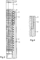
- FIG. 1 shows a fuel injection valve 1, which essentially consists of several, in the axial direction X-X the valve consists of successively arranged components.
- the components of the valve 1 are a holding body 2, a valve plate 3, a throttle plate 4 and a Nozzle body 5. These components of the valve are by means of a nozzle retaining nut 6 braced against each other. For this has the nozzle retaining nut 6 at its upper end portion Internal thread 10 (see Figure 2), with which they on a External thread 9 of the holder body 2 is screwed.
- a sealing element in the form of a Coating 8 arranged between the Internal thread 10 of the nozzle lock nut 6 and the external thread 9 of the holding body 2, a sealing element in the form of a Coating 8 arranged.
- the coating 8 can either on the internal thread 10 or the external thread 9 or on be applied to both threads.
- the coating 8 runs around the entire circumference of the thread. Through this coating 8 according to the invention becomes a safe Sealing a low pressure region of the valve 1 against the external environment is reached.
- the coating 8 is in the Essentially at the upper end region of the nozzle retaining nut 6 formed and has a height H, which is between 1/3 and 1/2 the height of the thread in the axial direction of the Valve is enough.
- the coating 8 can easily before Mounting on one or both threads are applied, so that the seal after unscrewing the Nozzle lock nut 6 is present on the holding body 2.
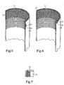
- the second embodiment as a sealing element Plastic ring 11 used.
- the Plastic ring in mounted condition i. at screwed nozzle retaining nut 6 on the holder body. 2 shown, and in Figure 4, the plastic ring 11 is present the assembly shown.
- the plastic ring 11 in the Mounting deformed so that it is close to the External thread 9 on the holding body 2 applies. This will be a adequate sealing between the low pressure area of the Valve and the outside reached.
- the plastic ring 11 has such a height that it is about 1/3 of the covered in engaging threads. Consequently forms the sealing element in the second embodiment itself a part of the thread, so that a simple and cost-effective sealing is achievable.
- the seal results when screwing the nozzle retaining nut on the holding body 2 automatically.
- thread on Holding body 2 is hereby preferably a M17x0.75 thread used.
- the plastic ring 11 is in one provided at the end of the nozzle retaining nut 6 Recess 12 is arranged.
- FIGs 5 to 7 are different Fixing possibilities for the fixation of the plastic ring 11 shown on the nozzle lock nut 6.
- two mutually 180 ° opposite Holes 14 are provided, in which two each formed according to the bore 14 above Intervene areas 13.
- a similar situation fixation of the Plastic rings 11 is shown in Figure 6, in which two opposing projecting portions 13 in two correspondingly formed grooves 15 at the upper end of the Engage nozzle retaining nut 6.
- the fixation of the in Figure 7 illustrated embodiment consists in a Flare 16, which to the inside of the nozzle lock nut. 6 is directed and fixed the plastic ring 11.
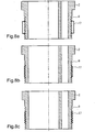
- FIGS. 8a to 8c a sealing element according to another is shown not inventive example shown.
- the sealing element according to these Example consists of a shrink tube 17, which on the external thread 9 of the holding body. 2 is applied.
- the shrink tube 17 is in tense state in which he is on the External thread 9 of the holding body 2 is applied. How out Figure 8a is apparent, the height of the Shrink tube 17 while about half the height of the thread 9.
- the shrink tube 17 is in mounted state in which he is on the Thread tips of the external thread 9 rests. If now the Nozzle tension nut on the external thread 9 of the holding body.
- the present invention relates to a valve for Controlling liquids, which several components 2, 3, 4, 5, which in the axial direction X-X of the valve arranged one after the other.
- At least one of the Components is an external thread 9 is formed with a Internal thread of a clamping nut 6 to come into engagement.
- the Clamping nut 6 is used to clamp the components of Valve.
- a sealing element 8, 11, 17 is between the Internal thread 10 of the clamping nut 6 and the external thread. 9 of the component 2 is arranged.
Landscapes
- Engineering & Computer Science (AREA)
- Chemical & Material Sciences (AREA)
- Combustion & Propulsion (AREA)
- Mechanical Engineering (AREA)
- General Engineering & Computer Science (AREA)
- Manufacturing & Machinery (AREA)
- Fuel-Injection Apparatus (AREA)
- Valve Housings (AREA)
Claims (5)
- Soupape de commande de liquides, comportant plusieurs composants (2, 3, 4, 5) disposés l'un après l'autre dans la direction axiale (X-X) de la soupape, dont au moins un composant (2) comporte un filetage externe (9) qui, quand la soupape est montée, est en prise avec un filetage interne (10) d'un écrou de serrage (6), et pour serrer les composants (2, 3, 4, 5) les uns sur les autres, un élément d'étanchéité (8 ; 11 ; 17), ayant la forme d'une bague en matière plastique (11) montée entre le filetage interne (10) de l'écrou de serrage (6) et le filetage externe (9) du composant (2),
caractérisée en ce que
la bague en matière plastique (11) présente au moins une zone en saillie (13) pour fixer sa position. - Soupape selon la revendication 1,
caractérisée en ce que
la bague en matière plastique (11) se trouve dans un évidement (12) formé dans l'écrou de serrage (6). - Soupape selon la revendication 2,
caractérisée en ce que
l'évidement (12) est situé vers l'extrémité de l'écrou de serrage (6). - Soupape selon la revendication 2 ou 3,
caractérisée en ce que
l'écrou de serrage (6) présente un bord rabattu (16) pour fixer la bague en matière plastique (11). - Soupape selon une des revendications 1 à 4,
caractérisée en ce qu'
une rainure est réalisée entre le composant (2) et une plaque de soupape (3) pour évacuer les fuites éventuelles vers une zone à basse pression de la soupape.
Applications Claiming Priority (3)
| Application Number | Priority Date | Filing Date | Title |
|---|---|---|---|
| DE10155413 | 2001-11-10 | ||
| DE10155413A DE10155413A1 (de) | 2001-11-10 | 2001-11-10 | Ventil zum Steuern von Flüssigkeiten |
| PCT/DE2002/004119 WO2003042531A1 (fr) | 2001-11-10 | 2002-11-07 | Soupape permettant de commander le passage de liquides |
Publications (2)
| Publication Number | Publication Date |
|---|---|
| EP1454057A1 EP1454057A1 (fr) | 2004-09-08 |
| EP1454057B1 true EP1454057B1 (fr) | 2005-09-28 |
Family
ID=7705411
Family Applications (1)
| Application Number | Title | Priority Date | Filing Date |
|---|---|---|---|
| EP02781154A Expired - Lifetime EP1454057B1 (fr) | 2001-11-10 | 2002-11-07 | Soupape permettant de commander le passage de liquides |
Country Status (8)
| Country | Link |
|---|---|
| US (1) | US6929247B2 (fr) |
| EP (1) | EP1454057B1 (fr) |
| JP (1) | JP4348185B2 (fr) |
| KR (1) | KR100935093B1 (fr) |
| CN (1) | CN100453799C (fr) |
| DE (2) | DE10155413A1 (fr) |
| ES (1) | ES2247390T3 (fr) |
| WO (1) | WO2003042531A1 (fr) |
Families Citing this family (13)
| Publication number | Priority date | Publication date | Assignee | Title |
|---|---|---|---|---|
| CA2370976C (fr) | 1999-04-20 | 2009-10-20 | Illumina, Inc. | Detection de reactions d'acide nucleique sur microsupports de billes en reseau |
| EP1644634B1 (fr) * | 2003-07-15 | 2006-11-02 | Siemens Aktiengesellschaft | Dispositif de dosage de fluide sous pression et sa methode de realisation |
| JP2006207480A (ja) * | 2005-01-28 | 2006-08-10 | Bosch Corp | 燃料噴射弁 |
| JP4632177B2 (ja) * | 2005-12-16 | 2011-02-16 | 小柳 司 | 使い捨て生分解性容器の製造方法 |
| DE102006060657A1 (de) | 2006-12-21 | 2008-07-03 | Robert Bosch Gmbh | Brennstoffeinspritzventil |
| DE102006062008A1 (de) | 2006-12-29 | 2008-07-03 | Robert Bosch Gmbh | Vorrichtung für Hochdruckanwendungen |
| DE102007002760A1 (de) * | 2007-01-18 | 2008-07-24 | Robert Bosch Gmbh | Kraftstoffinjektor mit integriertem Druckverstärker |
| DE102008043347A1 (de) | 2008-10-31 | 2010-05-06 | Robert Bosch Gmbh | Mess- und Prüfvorrichtung |
| DE102011076957A1 (de) * | 2011-06-06 | 2012-12-06 | Robert Bosch Gmbh | Kraftstoffeinspritzventil für Brennkraftmaschinen |
| DE102012208075A1 (de) * | 2012-05-15 | 2013-11-21 | Man Diesel & Turbo Se | Injektor für eine Kraftstoffversorgungsanlage einer Brennkraftmaschine sowie Kraftstoffversorgungsanlage |
| DE102016123055A1 (de) * | 2016-11-30 | 2018-05-30 | Man Diesel & Turbo Se | Kraftstoffversorgungsanlage und Kraftverteilerblock |
| TR201713993A2 (tr) * | 2017-09-21 | 2019-04-22 | Bosch Sanayi Ve Tic A S | Bi̇r yakit enjektörü |
| EP3935276A4 (fr) * | 2019-04-15 | 2022-10-19 | Cummins, Inc. | Injecteur de carburant avec trous de buse orientables radialement utilisant des splines |
Family Cites Families (14)
| Publication number | Priority date | Publication date | Assignee | Title |
|---|---|---|---|---|
| GB1210381A (en) * | 1967-01-13 | 1970-10-28 | Bryce Berger Ltd | Liquid fuel injection nozzle units for internal combustion engines |
| US4176822A (en) * | 1977-10-31 | 1979-12-04 | Chrysler Corporation | Fuel injection system and control valve for multi-cylinder engines |
| DE3000061C2 (de) * | 1980-01-03 | 1993-10-14 | Bosch Gmbh Robert | Kraftstoffeinspritzdüse für Brennkraftmaschinen |
| CN1015402B (zh) * | 1986-10-11 | 1992-02-05 | 瓦洛海克股份有限公司 | 在螺纹部分设有密封装置的钢管螺纹接头 |
| DE4317627C2 (de) * | 1993-05-27 | 1996-05-09 | Harald Schulz | Verfahren zur Instandhaltung eines Ventils für Gas- oder Flüssigkeitsleitungen |
| CN1045106C (zh) * | 1994-03-03 | 1999-09-15 | 中国科学院长春应用化学研究所 | 氟化物螺纹密封胶 |
| US5467963A (en) * | 1994-04-13 | 1995-11-21 | Cummins Engine Company, Inc. | Two-piece collet adjusting nut for a fuel injector solenoid valve |
| CN2260938Y (zh) * | 1996-08-16 | 1997-08-27 | 王力人 | 新型螺纹密封连接结构 |
| DE19645900A1 (de) * | 1996-11-07 | 1998-05-14 | Bosch Gmbh Robert | Kraftstoffeinspritzventil für Brennkraftmaschinen |
| US6047899A (en) * | 1998-02-13 | 2000-04-11 | Caterpillar Inc. | Hydraulically-actuated fuel injector with abrupt end to injection features |
| DE10017113B4 (de) * | 2000-04-06 | 2006-02-09 | Ina-Schaeffler Kg | Spannmutter |
| DE10121531A1 (de) * | 2001-05-03 | 2002-11-14 | Siemens Ag | Kraftstoffinjektor |
| DE10133167A1 (de) * | 2001-07-07 | 2003-01-23 | Bosch Gmbh Robert | Kraftstoffhochdruckvorrichtung |
| US6675049B2 (en) * | 2001-07-17 | 2004-01-06 | Medtronic, Inc. | Method and apparatus for automatic implantable medical lead recognition and configuration |
-
2001
- 2001-11-10 DE DE10155413A patent/DE10155413A1/de not_active Withdrawn
-
2002
- 2002-11-07 WO PCT/DE2002/004119 patent/WO2003042531A1/fr active IP Right Grant
- 2002-11-07 KR KR1020047006843A patent/KR100935093B1/ko not_active IP Right Cessation
- 2002-11-07 EP EP02781154A patent/EP1454057B1/fr not_active Expired - Lifetime
- 2002-11-07 ES ES02781154T patent/ES2247390T3/es not_active Expired - Lifetime
- 2002-11-07 US US10/250,775 patent/US6929247B2/en not_active Expired - Fee Related
- 2002-11-07 JP JP2003544331A patent/JP4348185B2/ja not_active Expired - Fee Related
- 2002-11-07 CN CNB028063139A patent/CN100453799C/zh not_active Expired - Fee Related
- 2002-11-07 DE DE50204423T patent/DE50204423D1/de not_active Expired - Lifetime
Also Published As
| Publication number | Publication date |
|---|---|
| CN1671962A (zh) | 2005-09-21 |
| EP1454057A1 (fr) | 2004-09-08 |
| DE10155413A1 (de) | 2003-05-22 |
| JP2005509781A (ja) | 2005-04-14 |
| CN100453799C (zh) | 2009-01-21 |
| DE50204423D1 (de) | 2005-11-03 |
| JP4348185B2 (ja) | 2009-10-21 |
| KR20040060971A (ko) | 2004-07-06 |
| KR100935093B1 (ko) | 2010-01-06 |
| US20040046059A1 (en) | 2004-03-11 |
| ES2247390T3 (es) | 2006-03-01 |
| US6929247B2 (en) | 2005-08-16 |
| WO2003042531A1 (fr) | 2003-05-22 |
Similar Documents
| Publication | Publication Date | Title |
|---|---|---|
| EP1454057B1 (fr) | Soupape permettant de commander le passage de liquides | |
| EP2665920B1 (fr) | Injecteur de carburant doté d'un raccord haute pression amélioré | |
| DE102013009650A1 (de) | Ventil | |
| DE102005052419B4 (de) | Schraubverbindung | |
| EP3371861B1 (fr) | Bougie d'allumage à couple de serrage augmenté | |
| DE102008008435B4 (de) | Federbelastetes Ventil und Verfahren zur Einstellung einer Ventilbaugruppe eines federbelasteten Ventils | |
| WO2000040857A1 (fr) | Raccord pour le retour de carburant de fuite et injecteur de carburant presentant un tel raccord | |
| DE4307650C2 (de) | Hochdruck-Leitungsverbindung | |
| WO2009019178A1 (fr) | Injecteur et dispositif comprenant un récipient et un boîtier entourant le récipient | |
| WO2014026846A1 (fr) | Assemblage vissé de composants conduisant un milieu sous haute pression | |
| EP3143274B1 (fr) | Arrangement d'alimentation en combustible pour un injecteur de carburant et injecteur de carburant | |
| DE19807819C1 (de) | Verfahren zur brennraumseitigen Abdichtung eines Einspritzventils einer Brennkraftmaschine | |
| EP3135898B1 (fr) | Systeme d'etancheification d'alimentation en carburant | |
| DE10022378A1 (de) | Hochdruckfester Injektorkörper | |
| EP1241348A2 (fr) | Raccord haute pression pour un système d'injection de carburant | |
| EP1298314A1 (fr) | Accumulateur de combustible pour un dispositif d'injection | |
| DE102021202697A1 (de) | Hochdruckspeicherleitung für ein Kraftstoffeinspritzsystem, Kraftstoffeinspritzsystem sowie Verwendung eines Drosselelements in einer Hochdruckspeicherleitung | |
| DE10309311A1 (de) | Kraftstoffhockdruckspeicher | |
| EP1880100B1 (fr) | Soupape d'injection de carburant pour moteurs a combustion interne | |
| DE19614982C1 (de) | Hochdruckleitungsanschluß | |
| WO2008043773A1 (fr) | Système de blocage de la rotation libre d'un élément fileté | |
| DE19959105A1 (de) | Anschlussstutzen und Gehäuse, insbesondere Kraftstoffhochdruckspeicher, mit vorgespannt angeschweißtem Anschlussstutzen für ein Kraftstoffeinspritzsystem für Brennkraftmaschinen | |
| EP3098434B1 (fr) | Systeme d'injection de carburant | |
| WO2002097260A2 (fr) | Dispositif d'amortissement des oscillations dans un systeme d'injection a accumulateur | |
| DE102007019986A1 (de) | Ventilanordnung für ein Einspritzventil |
Legal Events
| Date | Code | Title | Description |
|---|---|---|---|
| PUAI | Public reference made under article 153(3) epc to a published international application that has entered the european phase |
Free format text: ORIGINAL CODE: 0009012 |
|
| 17P | Request for examination filed |
Effective date: 20040611 |
|
| AK | Designated contracting states |
Kind code of ref document: A1 Designated state(s): AT BE BG CH CY CZ DE DK EE ES FI FR GB GR IE IT LI LU MC NL PT SE SK TR |
|
| 17Q | First examination report despatched |
Effective date: 20040927 |
|
| GRAP | Despatch of communication of intention to grant a patent |
Free format text: ORIGINAL CODE: EPIDOSNIGR1 |
|
| GRAS | Grant fee paid |
Free format text: ORIGINAL CODE: EPIDOSNIGR3 |
|
| GRAA | (expected) grant |
Free format text: ORIGINAL CODE: 0009210 |
|
| AK | Designated contracting states |
Kind code of ref document: B1 Designated state(s): DE ES FR GB IT |
|
| REG | Reference to a national code |
Ref country code: GB Ref legal event code: FG4D Free format text: NOT ENGLISH |
|
| REF | Corresponds to: |
Ref document number: 50204423 Country of ref document: DE Date of ref document: 20051103 Kind code of ref document: P |
|
| GBT | Gb: translation of ep patent filed (gb section 77(6)(a)/1977) |
Effective date: 20060112 |
|
| REG | Reference to a national code |
Ref country code: ES Ref legal event code: FG2A Ref document number: 2247390 Country of ref document: ES Kind code of ref document: T3 |
|
| ET | Fr: translation filed | ||
| PLBE | No opposition filed within time limit |
Free format text: ORIGINAL CODE: 0009261 |
|
| STAA | Information on the status of an ep patent application or granted ep patent |
Free format text: STATUS: NO OPPOSITION FILED WITHIN TIME LIMIT |
|
| 26N | No opposition filed |
Effective date: 20060629 |
|
| PGFP | Annual fee paid to national office [announced via postgrant information from national office to epo] |
Ref country code: GB Payment date: 20101123 Year of fee payment: 9 Ref country code: IT Payment date: 20101127 Year of fee payment: 9 |
|
| PGFP | Annual fee paid to national office [announced via postgrant information from national office to epo] |
Ref country code: ES Payment date: 20111123 Year of fee payment: 10 Ref country code: FR Payment date: 20111125 Year of fee payment: 10 |
|
| GBPC | Gb: european patent ceased through non-payment of renewal fee |
Effective date: 20121107 |
|
| REG | Reference to a national code |
Ref country code: FR Ref legal event code: ST Effective date: 20130731 |
|
| PG25 | Lapsed in a contracting state [announced via postgrant information from national office to epo] |
Ref country code: IT Free format text: LAPSE BECAUSE OF NON-PAYMENT OF DUE FEES Effective date: 20121107 |
|
| PG25 | Lapsed in a contracting state [announced via postgrant information from national office to epo] |
Ref country code: FR Free format text: LAPSE BECAUSE OF NON-PAYMENT OF DUE FEES Effective date: 20121130 Ref country code: GB Free format text: LAPSE BECAUSE OF NON-PAYMENT OF DUE FEES Effective date: 20121107 |
|
| REG | Reference to a national code |
Ref country code: ES Ref legal event code: FD2A Effective date: 20140305 |
|
| PG25 | Lapsed in a contracting state [announced via postgrant information from national office to epo] |
Ref country code: ES Free format text: LAPSE BECAUSE OF NON-PAYMENT OF DUE FEES Effective date: 20121108 |
|
| PGFP | Annual fee paid to national office [announced via postgrant information from national office to epo] |
Ref country code: DE Payment date: 20170126 Year of fee payment: 15 |
|
| REG | Reference to a national code |
Ref country code: DE Ref legal event code: R119 Ref document number: 50204423 Country of ref document: DE |
|
| PG25 | Lapsed in a contracting state [announced via postgrant information from national office to epo] |
Ref country code: DE Free format text: LAPSE BECAUSE OF NON-PAYMENT OF DUE FEES Effective date: 20180602 |