EP1452401A2 - Insassen-Rückhaltesystem - Google Patents
Insassen-Rückhaltesystem Download PDFInfo
- Publication number
- EP1452401A2 EP1452401A2 EP04250955A EP04250955A EP1452401A2 EP 1452401 A2 EP1452401 A2 EP 1452401A2 EP 04250955 A EP04250955 A EP 04250955A EP 04250955 A EP04250955 A EP 04250955A EP 1452401 A2 EP1452401 A2 EP 1452401A2
- Authority
- EP
- European Patent Office
- Prior art keywords
- occupant restraint
- seatbelt
- state
- occupant
- sensor unit
- Prior art date
- Legal status (The legal status is an assumption and is not a legal conclusion. Google has not performed a legal analysis and makes no representation as to the accuracy of the status listed.)
- Granted
Links
Images


Classifications
-
- E—FIXED CONSTRUCTIONS
- E04—BUILDING
- E04G—SCAFFOLDING; FORMS; SHUTTERING; BUILDING IMPLEMENTS OR AIDS, OR THEIR USE; HANDLING BUILDING MATERIALS ON THE SITE; REPAIRING, BREAKING-UP OR OTHER WORK ON EXISTING BUILDINGS
- E04G17/00—Connecting or other auxiliary members for forms, falsework structures, or shutterings
- E04G17/06—Tying means; Spacers ; Devices for extracting or inserting wall ties
- E04G17/07—Tying means, the tensional elements of which are fastened or tensioned by means of wedge-shaped members
- E04G17/0707—One-piece elements
- E04G17/0714—One-piece elements fully recoverable
-
- B—PERFORMING OPERATIONS; TRANSPORTING
- B60—VEHICLES IN GENERAL
- B60R—VEHICLES, VEHICLE FITTINGS, OR VEHICLE PARTS, NOT OTHERWISE PROVIDED FOR
- B60R21/00—Arrangements or fittings on vehicles for protecting or preventing injuries to occupants or pedestrians in case of accidents or other traffic risks
- B60R21/01—Electrical circuits for triggering passive safety arrangements, e.g. airbags, safety belt tighteners, in case of vehicle accidents or impending vehicle accidents
- B60R21/015—Electrical circuits for triggering passive safety arrangements, e.g. airbags, safety belt tighteners, in case of vehicle accidents or impending vehicle accidents including means for detecting the presence or position of passengers, passenger seats or child seats, and the related safety parameters therefor, e.g. speed or timing of airbag inflation in relation to occupant position or seat belt use
- B60R21/01512—Passenger detection systems
- B60R21/01544—Passenger detection systems detecting seat belt parameters, e.g. length, tension or height-adjustment
- B60R21/01546—Passenger detection systems detecting seat belt parameters, e.g. length, tension or height-adjustment using belt buckle sensors
-
- B—PERFORMING OPERATIONS; TRANSPORTING
- B60—VEHICLES IN GENERAL
- B60R—VEHICLES, VEHICLE FITTINGS, OR VEHICLE PARTS, NOT OTHERWISE PROVIDED FOR
- B60R21/00—Arrangements or fittings on vehicles for protecting or preventing injuries to occupants or pedestrians in case of accidents or other traffic risks
- B60R21/01—Electrical circuits for triggering passive safety arrangements, e.g. airbags, safety belt tighteners, in case of vehicle accidents or impending vehicle accidents
- B60R21/015—Electrical circuits for triggering passive safety arrangements, e.g. airbags, safety belt tighteners, in case of vehicle accidents or impending vehicle accidents including means for detecting the presence or position of passengers, passenger seats or child seats, and the related safety parameters therefor, e.g. speed or timing of airbag inflation in relation to occupant position or seat belt use
- B60R21/01512—Passenger detection systems
- B60R21/01544—Passenger detection systems detecting seat belt parameters, e.g. length, tension or height-adjustment
Definitions
- the present invention relates to an occupant restraint system responsive to states of wearing and operating a seatbelt.
- the control when controlling an airbag and a pretensioner, the control is performed on condition that an occupant is wearing a seatbelt system.
- the control of the airbag and the pretensioner is not performed on condition that the seatbelt system is operating, that is, on condition that an occupant is correctly wearing a seatbelt and further is fastened tightly by the seatbelt.
- the present invention was made in consideration of the above-described problems. It is an object of the present invention to provide an occupant restraint system which can perform proper occupant restraint control in accordance with states of wearing and operating a vehicle's seatbelt system.
- the first aspect of the present invention provides an occupant restraint system comprising: a first sensor unit which detects a state of wearing a seatbelt system; a second sensor unit which detects a state of operating the seatbelt system; and a controller which performs a control to change a time range to determine activation and expansion of a occupant restraint equipment upon a vehicle collision in accordance with signals from the first sensor unit and the second sensor unit, wherein when a state detected by the first sensor unit is a state of not wearing the seatbelt system, the controller performs a control to set a mode to a stopping mode which has a time range to determine the activation and expansion of the occupant restraint equipment upon a vehicle collision, and when a state detected by the first sensor unit is a state of wearing the seatbelt system and a state detected by the second sensor unit is a state of operating the seatbelt system, the controller performs a control to set the mode to an operating mode which has a smaller time range to determine the activation and expansion of the
- the second aspect of the present invention provides a method for restraining an occupant, comprising: detecting a state of wearing a seatbelt system; detecting a state of operating the seat belt system; performing a control to set a mode to a stopping mode which has a time range to determine the activation and expansion of an occupant restraint equipment upon a vehicle collision when the seatbelt system is in a state of not being worn, and to set the mode to an operating mode which has a smaller time range to determine the activation and expansion of the occupant restraint equipment upon the vehicle collision than that in the state of not wearing the seatbelt system when the seatbelt system is in a state of being worn and operated.
- An occupant restraint system 10 of the present invention is configured as shown in FIG. 1.
- the occupant restraint system 10 of the present invention is mounted on a vehicle and includes an occupant restraint device 1 and a vehicle's seatbelt system 2.
- the occupant restraint device 1 (corresponding to a controller) performs control of timing to activate and deploy equipment for restraining an occupant, or occupants, in a vehicle.
- the occupant restraint device 1 is connected to a driver's seat airbag system 11 for an occupant seated in a driver's seat, to a front-passenger's seat airbag system 12 for an occupant seated in a front-passenger's seat, and to a pretensioner 13.
- the occupant restraint device 1 expands the driver's seat airbag system 11 and the front-passenger's seat airbag system 12, and activates the pretensioner 13, thereby performing a control to restrain the occupants seated in the driver's seat and in the front-passenger's seat.
- the driver's seat airbag system 11, the front-passenger's seat airbag system 12 and the pretensioner 13 are collectively referred to also as occupant restraint equipment in this specification.
- a gas generator of an ignition type instantaneously inflates an air cushion (airbag), thereby protecting the head and chest of an occupant from interior equipment including a steering wheel, an instrument panel, doors, B pillars, and the like.
- the pretensioner 13 (seatbelt tensioner 13) immediately winds up a seatbelt 14, and exerts a tensile force on the occupant, and thus the occupant is restrained.
- the pretensioner 13 is configured to instantaneously wind up the seatbelt 14 with an explosive force using an explosive or a spring upon a vehicle collision.
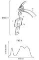
- the seatbelt 14 is worn in such a manner that the seatbelt 14 is drawn out from a retractor (not shown) which is fixed to a lower portion of a pillar 16 on a body side, or the like; a tongue 18 is mechanically inserted into a buckle 17 on the body side and fixed thereto.
- a retractor not shown
- a tongue 18 is mechanically inserted into a buckle 17 on the body side and fixed thereto.
- the vehicle's seatbelt system 2 in the occupant restraint system 10 of the present invention includes the seatbelt 14. Further, the vehicle's seatbelt system 2 is connected to a unit (corresponding to a first sensor unit) for detecting a state of wearing the seatbelt 14 which is worn by an occupant seated in the driver's seat or in the front-passenger's seat. Specifically, the vehicle's seatbelt system 2 is connected to a switch 19 serving as the first sensor unit for detecting whether or not the tongue 18 of the seatbelt 14 is connected to the buckle 17. When the tongue 18 is inserted into the buckle 17 and fixed thereto, a connection signal is sent from the switch 19, as the first sensor unit, to the vehicle's seatbelt system 2.
- a connection signal is sent from the switch 19, as the first sensor unit, to the vehicle's seatbelt system 2.
- the occupant restraint system 10 of the present invention is applied to a vehicle including a pre-crash seatbelt system.
- a pre-crash seatbelt system As shown in FIG. 2, at the lower portion of the pillar 16, the pretensioner 13 and a motor 15 that is included in the pre-crash seatbelt system are provided. Further, the seatbelt 14 is connected to both the pretensioner 13 and the motor 15.
- the pre-crash seatbelt system is a system of winding up the seatbelt 14 with the motor 15 to restrain an occupant before a vehicle collision, that is, when a collision avoidance maneuver is possible.
- a mechanism for anticipating a collision a mechanism is employed.
- a mechanism which includes a radar in front of a vehicle, measures a distance between the vehicle and an obstacle in front, and anticipates a collision.
- a mechanism is also employed which detects driver's braking operation before a collision, that is, emergency braking operation performed by the driver before a collision.
- the mechanism for anticipating a collision is not limited to these mechanisms. Any mechanism can be employed as long as it anticipates a collision.
- a signal is sent from a collision anticipating mechanism to an ECU when a vehicle is likely to collide against an obstacle in front. The ECU then outputs an activating signal to the motor 15, and the motor 15 winds up the seatbelt 14, thus restraining an occupant.
- a tensile force on the seatbelt at this time is less than that exerted when the seatbelt 14 is wound up by the pretensioner 13. Accordingly, the occupant is restrained to such an extent that the occupant can still handle a steering wheel and avoid a collision.
- the vehicle's seatbelt system 2 is connected to a unit (corresponding to a second sensor unit) for detecting that the motor 15 is operating.
- the occupant restraint system 10 of the present invention including the above-described occupant restraint device 1 and vehicle's seatbelt system 2, is characterized by optimally activating and expanding the occupant restraint equipment by changing a time period to judge the activation and expansion of the occupant restraint equipment in accordance with states of wearing and operating the seatbelt 14. This will be described in detail below.
- the pretensioner 13 Upon the collision, the pretensioner 13 is activated and instantaneously winds up the seatbelt 14, thereby firmly restraining the occupant. Accordingly, there is less possibility that the occupant strikes his/her head and chest on the steering wheel and/or the windshield.
- the occupant restraint system 10 of the present invention is characterized by securing a calculation time to determine whether or not to activate and expand the occupant restraint equipment, and activating and expanding the occupant restraint equipment at more proper timing, in such a manner that the occupant restraint device 1 as a controller changes a time period to determine the activation and expansion of the occupant restraint equipment in accordance with states of wearing and operating the seatbelt.
- the state of wearing the seatbelt is a state where the tongue 18 of the seatbelt 14 is inserted into the buckle 17 and fixed thereto, that is, a state where an occupant wears the seatbelt 14.
- the state of operating the seatbelt is a state where a signal is sent from the collision anticipating mechanism to the ECU and the motor 15 winds up the seatbelt 14.
- a threshold ⁇ V0 for the determination of activation and expansion is reduced, thus advancing the activation and expansion.
- the threshold is a target value to activate and expand the occupant restraint equipment when the velocity ⁇ V reaches the threshold ⁇ V0.
- the activation and expansion of the occupant restraint equipment is possible in a range from a velocity ⁇ V1 to a velocity ⁇ V2 with the threshold ⁇ V0 in the middle of the range.
- the occupant restraint device 1 starts activating and expanding the occupant restraint equipment while the velocity is in the range from ⁇ V1 to ⁇ V2.
- the threshold ⁇ V0 is set low.
- the activation/expansion determination time period is increased, and therefore a calculation time period is reduced.
- Control of modes between the stopping mode and the operating mode is performed based on signals sent from the first sensor unit and from the second sensor unit to the vehicle's seatbelt system 2. Specifically, when the seatbelt is worn, an ON signal shown in FIG. 7 is sent from the first sensor unit to the vehicle's seatbelt system 2. Further, when the vehicle is likely to collide against an obstacle in front, a signal is sent from the collision anticipating mechanism to the motor 15, and the motor 15 then winds up the seatbelt 14. When the second sensor unit detects this operation of the motor 15, a similar ON signal is sent to the vehicle's seatbelt system 2.
- an ON signal is sent from the vehicle's seatbelt system 2 to the occupant restraint device 1.
- the occupant restraint device 1 then performs a control to change the mode from the stopping mode to the operating mode, to raise the threshold ⁇ V0, and to reduce the activation/expansion determination time range.
- processing from a step S1 is started for every predetermined time period.
- the occupant restraint device 1 sets the threshold ⁇ V0 for the event of the activation and expansion of the occupant restraint equipment to a value in the stopping mode. The processing then proceeds to a step S2.
- step S2 by judging, in the occupant restraint device 1, whether an operation signal from the vehicle's seatbelt system 2 is ON or not, it is judged whether or not an occupant is wearing the seatbelt 14 and whether or not the motor 15 is operating.
- the mode is controlled to be kept in the stopping mode, and the processing returns to the step S1.
- the processing proceeds to a step S3.
- the occupant restraint device 1 performs a control to change the mode from the stopping mode to the operating mode, thereby raising the threshold ⁇ V0 and reducing the range of ⁇ V1 to ⁇ V2. The processing then returns to the step S2.
- the sensor units for detecting states of wearing and operating the seatbelt 14 are connected to the vehicle's seatbelt system 2.
- a signal is sent from the vehicle's seatbelt system 2 to the occupant restraint device 1 to change the mode from the stopping mode to the operating mode.
- the occupant restraint system of the present invention is applied to a vehicle equipped with a pre-crash seatbelt system. Therefore, since an occupant is restrained to some extent by the motor 15 operating before a vehicle collision, the amount of movement of the occupant toward the front of the vehicle can be kept to a minimum. Subsequently, the occupant restraint system of the present invention allows the occupant restraint equipment to start operating at an optimal timing. Accordingly, it is possible to securely prevent the occupant from colliding against the interior equipment.
- another pretensioner 20 may be provided at a lower portion than the pretensioner 13 (first pretensioner 13) in the pillar 16 to form double pretensioners.
- second pretensioner 20 may be provided at a lower portion than the pretensioner 13 (first pretensioner 13) in the pillar 16 to form double pretensioners.
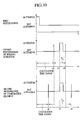
- the occupant restraint device 1 receives an operation signal from the vehicle's seatbelt system 2 and performs a control to change the mode from the stopping mode to the operating mode before a collision. Thereafter, when the vehicle collides against an obstacle in front, the first pretensioner 13 is activated first, and then the second pretensioner is activated. In the occupant restraint system 10 of the present invention, a time period after the activation of the first pretensioner 13 before time t2 is allocated as calculation time until the determination of the activation of the second pretensioner 20, and the second pretensioner 20 is activated at time t3.
- a time period from the time t2 to time t4 is an activation/expansion determination time range Tg'.
- a time period from time t1 to time t5 is an activation/expansion determination time range Tg. Accordingly, by using the occupant restraint system 10 of the present invention, it is possible to shorten the activation/expansion determination time period to prolong the calculation time period even in the case of double pretensioners. Therefore, it is possible to activate the second pretensioner 20 at optimal timing.
- the occupant restraint equipment although the driver's seat airbag system, the front-passenger's seat airbag system, and the pretensioner are shown in this specification, other equipment which restrains the movement of an occupant in the event of a vehicle collision may be used.
- the motor 15 is used when the seatbelt is wound up, a device or a system is not limited to a motor, and various types of winding device or system may be used.
- the second pretensioner is arranged in the vicinity of the first pretensioner, the second pretensioner may be arranged in the vicinity of the buckle 17.
Applications Claiming Priority (2)
| Application Number | Priority Date | Filing Date | Title |
|---|---|---|---|
| JP2003047581 | 2003-02-25 | ||
| JP2003047581A JP3951937B2 (ja) | 2003-02-25 | 2003-02-25 | 乗員拘束装置 |
Publications (3)
| Publication Number | Publication Date |
|---|---|
| EP1452401A2 true EP1452401A2 (de) | 2004-09-01 |
| EP1452401A3 EP1452401A3 (de) | 2004-11-03 |
| EP1452401B1 EP1452401B1 (de) | 2006-04-19 |
Family
ID=32767725
Family Applications (1)
| Application Number | Title | Priority Date | Filing Date |
|---|---|---|---|
| EP04250955A Expired - Fee Related EP1452401B1 (de) | 2003-02-25 | 2004-02-23 | Insassen-Rückhaltesystem |
Country Status (6)
| Country | Link |
|---|---|
| US (1) | US7204334B2 (de) |
| EP (1) | EP1452401B1 (de) |
| JP (1) | JP3951937B2 (de) |
| KR (1) | KR100581044B1 (de) |
| CN (2) | CN2706370Y (de) |
| DE (1) | DE602004000654T2 (de) |
Families Citing this family (14)
| Publication number | Priority date | Publication date | Assignee | Title |
|---|---|---|---|---|
| KR100551297B1 (ko) * | 2003-07-04 | 2006-02-10 | 현대자동차주식회사 | 시트 벨트 경고 기능을 갖는 에어백 시스템 |
| DE102004041425B3 (de) * | 2004-08-27 | 2005-10-06 | Bayerische Motoren Werke Ag | Rückhaltesystem für ein Kraftfahrzeug |
| US8348306B2 (en) | 2010-08-09 | 2013-01-08 | Toyota Motor Engineering And Manufacturing North America, Inc. | Vehicle restraint system |
| CN102529871A (zh) * | 2010-12-07 | 2012-07-04 | 苏州巴米特信息科技有限公司 | 一种基于安全气囊的新型防护方法 |
| JP5377582B2 (ja) * | 2011-06-30 | 2013-12-25 | 富士重工業株式会社 | 乗員保護装置 |
| JP5377583B2 (ja) | 2011-06-30 | 2013-12-25 | 富士重工業株式会社 | 乗員保護装置 |
| JP5572597B2 (ja) | 2011-06-30 | 2014-08-13 | 富士重工業株式会社 | 乗員保護装置 |
| EP2808206B1 (de) * | 2013-05-27 | 2017-07-12 | Volvo Car Corporation | Verfahren und system eines fahrzeugs für umkehrbares aufrollen des sicherheitsgurts |
| EP3018010B1 (de) * | 2014-11-06 | 2018-01-10 | Volvo Car Corporation | Verfahren zur Steuerung einer Aktivierungszeit eines reversiblen Rückhaltesystems in einem Fahrzeug |
| DE102016208828B4 (de) | 2015-07-24 | 2019-12-12 | Ford Global Technologies, Llc | Vorrichtung und Verfahren zur Verbesserung wenigstens einer unfallbezogen sicherheitsrelevanten Trageeigenschaft eines von einer in einem Fahrzeugsitz sitzenden Person angelegten Sicherheitsgurts |
| US10493937B2 (en) * | 2017-02-01 | 2019-12-03 | Ford Global Technologies, Llc | Restraint device deployment calibration |
| CN113511166B (zh) * | 2020-04-10 | 2022-10-25 | 采埃孚汽车科技(上海)有限公司 | 用于车辆的乘员约束系统、约束方法以及介质 |
| CN111559335A (zh) * | 2020-04-21 | 2020-08-21 | 汉腾汽车有限公司 | 一种预紧式安全带点火策略控制方法 |
| JP2022148124A (ja) * | 2021-03-24 | 2022-10-06 | 本田技研工業株式会社 | 車両用シートベルト装置、張力制御方法、およびプログラム |
Citations (1)
| Publication number | Priority date | Publication date | Assignee | Title |
|---|---|---|---|---|
| JPH06286581A (ja) | 1993-03-31 | 1994-10-11 | Nissan Motor Co Ltd | 乗物用シートベルト装置 |
Family Cites Families (9)
| Publication number | Priority date | Publication date | Assignee | Title |
|---|---|---|---|---|
| DE3932417A1 (de) | 1989-09-28 | 1991-04-18 | Audi Ag | Rueckhaltesystem fuer fahrzeuge |
| JPH06288581A (ja) | 1993-04-01 | 1994-10-11 | Mitsubishi Heavy Ind Ltd | 空気調和機 |
| US6241280B1 (en) * | 1998-09-01 | 2001-06-05 | Volkswagen Ag | Motor vehicle passenger safety arrangement |
| JP3541725B2 (ja) | 1999-05-20 | 2004-07-14 | 日産自動車株式会社 | 自動車用二段点火式エアバッグ装置 |
| US6327528B1 (en) | 2000-02-11 | 2001-12-04 | International Truck Intellectual Property Company L.L.C. | Method and apparatus for conditioning deployment of air bags on vehicle load |
| US6448890B1 (en) | 2000-05-01 | 2002-09-10 | Breed Automotive Technology, Inc. | Air bag system with biomechanical gray zones |
| JP2002029365A (ja) | 2000-06-14 | 2002-01-29 | Takata Corp | アクチュエータ制御方法 |
| JP2002178873A (ja) | 2000-12-18 | 2002-06-26 | Fujitsu Ten Ltd | 乗員保護装置 |
| US6874819B2 (en) * | 2003-08-20 | 2005-04-05 | Key Safety Systems, Inc. | Seat belt sensing for vehicle occupant load and misuse |
-
2003
- 2003-02-25 JP JP2003047581A patent/JP3951937B2/ja not_active Expired - Fee Related
-
2004
- 2004-02-10 US US10/774,541 patent/US7204334B2/en not_active Expired - Fee Related
- 2004-02-23 EP EP04250955A patent/EP1452401B1/de not_active Expired - Fee Related
- 2004-02-23 DE DE602004000654T patent/DE602004000654T2/de not_active Expired - Lifetime
- 2004-02-23 KR KR1020040011871A patent/KR100581044B1/ko not_active IP Right Cessation
- 2004-02-25 CN CNU2004200038937U patent/CN2706370Y/zh not_active Expired - Lifetime
- 2004-02-25 CN CNB2004100066382A patent/CN1270924C/zh not_active Expired - Fee Related
Patent Citations (1)
| Publication number | Priority date | Publication date | Assignee | Title |
|---|---|---|---|---|
| JPH06286581A (ja) | 1993-03-31 | 1994-10-11 | Nissan Motor Co Ltd | 乗物用シートベルト装置 |
Also Published As
| Publication number | Publication date |
|---|---|
| DE602004000654D1 (de) | 2006-05-24 |
| JP3951937B2 (ja) | 2007-08-01 |
| CN1524742A (zh) | 2004-09-01 |
| EP1452401A3 (de) | 2004-11-03 |
| DE602004000654T2 (de) | 2007-04-05 |
| EP1452401B1 (de) | 2006-04-19 |
| US20040163871A1 (en) | 2004-08-26 |
| CN1270924C (zh) | 2006-08-23 |
| KR20040076612A (ko) | 2004-09-01 |
| US7204334B2 (en) | 2007-04-17 |
| KR100581044B1 (ko) | 2006-05-16 |
| JP2004255965A (ja) | 2004-09-16 |
| CN2706370Y (zh) | 2005-06-29 |
Similar Documents
| Publication | Publication Date | Title |
|---|---|---|
| CN107521448B (zh) | 用于控制车辆的安全装置的操作的方法及控制装置 | |
| US7686340B2 (en) | Occupant restraint system and method for restraining occupant in seat of vehicle | |
| US7890263B2 (en) | System and method for sensing and deployment control supervision of a safety device | |
| JP4591750B2 (ja) | 車両の乗員保護装置 | |
| US10668895B2 (en) | Variable force limiter control system for vehicle | |
| US7204334B2 (en) | Occupant restraint system | |
| JP5286180B2 (ja) | 乗員保護制御装置 | |
| JP2002019555A (ja) | 乗員保護装置 | |
| US10906492B2 (en) | Passenger protection apparatus for vehicle | |
| JP2004521014A (ja) | ベルト引締力制限装置付き乗員拘束装置 | |
| JP2000127891A (ja) | 車両用乗員保護装置の点火制御方法 | |
| JP7408507B2 (ja) | 乗員保護装置 | |
| KR20140011833A (ko) | 차량의 후석 승객 보호 장치 및 그 제어 방법 | |
| US7134521B2 (en) | System for activating passenger-protecting device mounted on automotive vehicle | |
| JP3721451B2 (ja) | 車両用乗員保護装置 | |
| EP2708423B1 (de) | Insassenzurückhaltesystem und verfahren zur insassenzurückhaltung | |
| JP4088240B2 (ja) | 車両のシートベルト装置 | |
| US20060090946A1 (en) | Vehicle side collision occupant restraint system | |
| EP0931706A1 (de) | Vorrichtung und Verfahren zum Schutz eines Fahrzeuginsassen | |
| JP4133749B2 (ja) | 車両のシートベルト装置 | |
| EP1031475A2 (de) | System zum Schutz gegen einen Heckaufprall | |
| US20240051488A1 (en) | Occupant Protection System | |
| CN114364581B (zh) | 乘坐者保护系统 | |
| JP2002225672A (ja) | 車両用エアバッグの展開制御装置 | |
| JP2007191074A (ja) | 車両用エアベルト装置 |
Legal Events
| Date | Code | Title | Description |
|---|---|---|---|
| PUAI | Public reference made under article 153(3) epc to a published international application that has entered the european phase |
Free format text: ORIGINAL CODE: 0009012 |
|
| 17P | Request for examination filed |
Effective date: 20040303 |
|
| AK | Designated contracting states |
Kind code of ref document: A2 Designated state(s): AT BE BG CH CY CZ DE DK EE ES FI FR GB GR HU IE IT LI LU MC NL PT RO SE SI SK TR |
|
| AX | Request for extension of the european patent |
Extension state: AL LT LV MK |
|
| PUAL | Search report despatched |
Free format text: ORIGINAL CODE: 0009013 |
|
| AK | Designated contracting states |
Kind code of ref document: A3 Designated state(s): AT BE BG CH CY CZ DE DK EE ES FI FR GB GR HU IE IT LI LU MC NL PT RO SE SI SK TR |
|
| AX | Request for extension of the european patent |
Extension state: AL LT LV MK |
|
| 17Q | First examination report despatched |
Effective date: 20050311 |
|
| AKX | Designation fees paid |
Designated state(s): DE FR GB |
|
| GRAP | Despatch of communication of intention to grant a patent |
Free format text: ORIGINAL CODE: EPIDOSNIGR1 |
|
| GRAS | Grant fee paid |
Free format text: ORIGINAL CODE: EPIDOSNIGR3 |
|
| GRAA | (expected) grant |
Free format text: ORIGINAL CODE: 0009210 |
|
| AK | Designated contracting states |
Kind code of ref document: B1 Designated state(s): DE FR GB |
|
| RAP1 | Party data changed (applicant data changed or rights of an application transferred) |
Owner name: NISSAN MOTOR COMPANY LIMITED |
|
| REG | Reference to a national code |
Ref country code: GB Ref legal event code: FG4D |
|
| REF | Corresponds to: |
Ref document number: 602004000654 Country of ref document: DE Date of ref document: 20060524 Kind code of ref document: P |
|
| ET | Fr: translation filed | ||
| PLBE | No opposition filed within time limit |
Free format text: ORIGINAL CODE: 0009261 |
|
| STAA | Information on the status of an ep patent application or granted ep patent |
Free format text: STATUS: NO OPPOSITION FILED WITHIN TIME LIMIT |
|
| 26N | No opposition filed |
Effective date: 20070122 |
|
| PGFP | Annual fee paid to national office [announced via postgrant information from national office to epo] |
Ref country code: FR Payment date: 20140211 Year of fee payment: 11 |
|
| PGFP | Annual fee paid to national office [announced via postgrant information from national office to epo] |
Ref country code: GB Payment date: 20140219 Year of fee payment: 11 |
|
| PGFP | Annual fee paid to national office [announced via postgrant information from national office to epo] |
Ref country code: DE Payment date: 20140417 Year of fee payment: 11 |
|
| REG | Reference to a national code |
Ref country code: DE Ref legal event code: R119 Ref document number: 602004000654 Country of ref document: DE |
|
| GBPC | Gb: european patent ceased through non-payment of renewal fee |
Effective date: 20150223 |
|
| REG | Reference to a national code |
Ref country code: FR Ref legal event code: ST Effective date: 20151030 |
|
| PG25 | Lapsed in a contracting state [announced via postgrant information from national office to epo] |
Ref country code: GB Free format text: LAPSE BECAUSE OF NON-PAYMENT OF DUE FEES Effective date: 20150223 Ref country code: DE Free format text: LAPSE BECAUSE OF NON-PAYMENT OF DUE FEES Effective date: 20150901 |
|
| PG25 | Lapsed in a contracting state [announced via postgrant information from national office to epo] |
Ref country code: FR Free format text: LAPSE BECAUSE OF NON-PAYMENT OF DUE FEES Effective date: 20150302 |