EP1452323B1 - Tintenpatrone - Google Patents
Tintenpatrone Download PDFInfo
- Publication number
- EP1452323B1 EP1452323B1 EP04011374A EP04011374A EP1452323B1 EP 1452323 B1 EP1452323 B1 EP 1452323B1 EP 04011374 A EP04011374 A EP 04011374A EP 04011374 A EP04011374 A EP 04011374A EP 1452323 B1 EP1452323 B1 EP 1452323B1
- Authority
- EP
- European Patent Office
- Prior art keywords
- ink
- ink supply
- packing member
- valve body
- supply needle
- Prior art date
- Legal status (The legal status is an assumption and is not a legal conclusion. Google has not performed a legal analysis and makes no representation as to the accuracy of the status listed.)
- Expired - Lifetime
Links
Images


Classifications
-
- B—PERFORMING OPERATIONS; TRANSPORTING
- B41—PRINTING; LINING MACHINES; TYPEWRITERS; STAMPS
- B41J—TYPEWRITERS; SELECTIVE PRINTING MECHANISMS, i.e. MECHANISMS PRINTING OTHERWISE THAN FROM A FORME; CORRECTION OF TYPOGRAPHICAL ERRORS
- B41J2/00—Typewriters or selective printing mechanisms characterised by the printing or marking process for which they are designed
- B41J2/005—Typewriters or selective printing mechanisms characterised by the printing or marking process for which they are designed characterised by bringing liquid or particles selectively into contact with a printing material
- B41J2/01—Ink jet
- B41J2/17—Ink jet characterised by ink handling
- B41J2/175—Ink supply systems ; Circuit parts therefor
- B41J2/17503—Ink cartridges
- B41J2/17513—Inner structure
-
- B—PERFORMING OPERATIONS; TRANSPORTING
- B41—PRINTING; LINING MACHINES; TYPEWRITERS; STAMPS
- B41J—TYPEWRITERS; SELECTIVE PRINTING MECHANISMS, i.e. MECHANISMS PRINTING OTHERWISE THAN FROM A FORME; CORRECTION OF TYPOGRAPHICAL ERRORS
- B41J2/00—Typewriters or selective printing mechanisms characterised by the printing or marking process for which they are designed
- B41J2/005—Typewriters or selective printing mechanisms characterised by the printing or marking process for which they are designed characterised by bringing liquid or particles selectively into contact with a printing material
- B41J2/01—Ink jet
- B41J2/17—Ink jet characterised by ink handling
- B41J2/175—Ink supply systems ; Circuit parts therefor
- B41J2/17503—Ink cartridges
- B41J2/1752—Mounting within the printer
- B41J2/17523—Ink connection
-
- B—PERFORMING OPERATIONS; TRANSPORTING
- B41—PRINTING; LINING MACHINES; TYPEWRITERS; STAMPS
- B41J—TYPEWRITERS; SELECTIVE PRINTING MECHANISMS, i.e. MECHANISMS PRINTING OTHERWISE THAN FROM A FORME; CORRECTION OF TYPOGRAPHICAL ERRORS
- B41J2/00—Typewriters or selective printing mechanisms characterised by the printing or marking process for which they are designed
- B41J2/005—Typewriters or selective printing mechanisms characterised by the printing or marking process for which they are designed characterised by bringing liquid or particles selectively into contact with a printing material
- B41J2/01—Ink jet
- B41J2/17—Ink jet characterised by ink handling
- B41J2/175—Ink supply systems ; Circuit parts therefor
- B41J2/17596—Ink pumps, ink valves
Definitions
- the present invention relates to a printing apparatus for ejecting ink on a printing medium from a print head supplied with ink through a tapered ink supply needle, and more particularly to an ink cartridge and an ink supply system removably attached to the printing apparatus.
- an ink cartridge having a supply port for providing ink is connected to a print head of a printing apparatus for ejecting ink on a printing medium from nozzle aperture of the print head.
- the printing apparatus has a hollow ink supply needle in the ink supply channel to supply ink to the print head.
- the hollow ink supply needle is inserted into the ink supply port of the ink cartridge so that ink is introduced to the print head.
- the ink cartridge When the ink cartridge includes a porous member within its ink chamber for absorbing ink, the ink chamber is depressurized by the porous member. Therefore, the ink cartridge needs to be sealed not to suck undesired air or bubbles in the ink chamber.
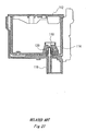
- Fig. 27 is a cross sectional view of an example of an ink cartridge and an ink supply channel.
- the ink cartridge 112 has an ink supply port 114 and a packing member 120 contained in the ink supply port 114 and fitting with an ink supply needle 118 which is connected to a print head 116.
- the ink supply port 114 is sealed with a sealing film, not shown in the drawings, prior to use.
- the ink supply needle 118 is inserted in the ink supply port 114 and fitted in the packing member 120, the ink supply needle 218 penetrates the sealing film. Ink is then provided to the print head 116 via the ink supply needle 118.
- the ink cartridge 112 is sealed by fitting the ink supply needle 118 with the packing member 120.
- an ink cartridge as disclosed, for example, in US patent No. 5, 777, 646, having an elastic slit wall formed at an opening of an ink supply port and a ball slidably received in the ink supply port which is always urged against the elastic slit wall by a spring.
- An ink supply channel of the conventional ink cartridge described above is opened by urging the ball with a hollow ink supply needle of the printing apparatus when the ink cartridge is mounted on the apparatus.
- the ink supply channel of the ink cartridge is closed when the hollow ink supply needle is removed from elastic: slit wall because of the elastic force of the spring which always urges the ball against the elastic slit wall of the ink supply port. Therefore, ink does not leak from the ink supply port and air or bubble does not enter the ink supply port.
- the conventional ink cartridge however, has a drawback that the structure of the ink supply port is complicated as shown in Fig. 27. Therefore, the workability of the ink cartridge is deteriorated, and the manufacturing cost would rise up.
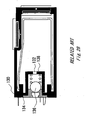
- Fig. 28 shows another example of a conventional ink cartridge disclosed in Japanese patent application No. 5-229137 employing a packing member, or a rubber member disposed in the ink supply port and a ball which is urged against the packing member by a spring.
- Ink is supplied from an ink chamber to a print head via a cylindrical connecting means.
- the ball is urged by the cylindrical connecting means to move away from the packing member against the elastic force of the spring.
- the ink cartridge illustrated in Fig. 28 has a packing member 134 disposed in the ink supply port 132 and a ball 136 abutting against the packing member 134 by means of an elastic force of a spring 138.
- the packing member 134 serves as a valve seat sealing the ink supply port 132 with the connecting means
- the ball 136 serves as a valve body closing the ink supply port 132 in cooperation with the packing member 134.
- the relative position between the ball 136 and the spring 138 is unstable. This may cause an undesirable insufficient sealing by the ball 136 with the packing member 134.
- the connecting means needs to have a large contact area to sufficiently urge the ball 136 against the elastic force of the spring. Therefore, the connecting means does not easily inserted in the packing member 134.
- the through hole of the packing member 134 may be expanded. This is disadvantageous because it may cause an insufficient connection between the ball 136 and the packing member 134.
- US 4,757,331 discloses a recording apparatus having a fixed tank being connectable to the printhead via a tube and a valve device.
- An ink cartridge according to the preamble of claim 1 is known from JP 08-183185.
- the present invention was made in view of the foregoing problems or drawbacks accompanying the conventional sealing structure of the conventional ink cartridge. Therefore, it is an object of the present invention to provide an ink cartridge and an ink supply system for an ink jet type printing apparatus capable of closing an ink supply channel assuredly, sufficiently when it is not mounted on the printing apparatus and capable of opening the ink supply channel to allow ink to smoothly flow to a print head when it is mounted on the printing apparatus.
- the present invention further provides an ink cartridge for a printing apparatus providing ink to a print head through an ink supply needle and removably attached to the print head, including: an ink chamber for containing ink; an ink supply port for supplying ink from the ink chamber to the print head of the printing apparatus, ink supply port including an external opening; a packing member provided in the ink supply port, forming an ink channel for allowing a flow of ink, the packing member sealing the ink supply needle of the printing apparatus by fitting therewith; and a valve device contained in the ink supply port elastically abutting against the packing member, the valve device selectively opening and closing the ink channel in conjunction with the ink supply needle, the valve device including: a valve body contacting with the packing member and urged by the ink supply needle of the printing apparatus to open the ink channel when the ink cartridge is mounted on the printing apparatus; and a guide body for guiding the valve body to
- the guide body includes: an axial portion being connected to the valve body; and a guide block formed at an end of the axial portion opposite to the valve body, the guide block guiding the valve body to slide substantially vertically with respect to the packing member.
- the valve device may include: a valve member selectively contacting with a surface of the packing member, the valve member being forced by the ink supply needle of the printing apparatus when the ink cartridge is mounted, on the printing apparatus; and an elastic member always urging the valve member toward the packing member.
- the valve member may include a support structure for supporting the elastic member.
- the support structure may be radially shaped.
- the valve member may include a flange for supporting the elastic member.
- the packing member may also include a second surface facing the external opening with a tapered portion tapered from the external opening toward the ink chamber at the second surface, for guiding the ink supply needle of the printing apparatus.
- the tapered portion may fit with the ink supply needle.
- the packing member may include a second surface facing the external opening with a fitting portion to fit with the ink supply needle of the printing apparatus.
- the packing member may be made of an elastic material and provided with a lubricant coat at least at an area with which the ink supply needle contacts.
- the valve device may include a substantially flat surface with which the ink supply needle contacts.
- the valve body may include: a sealing portion for closing the ink channel of the packing member when the valve body contacts with the packing member; and an ink channel allowing ink to pass therethrough when the valve body is urged to come out of contact with the packing member by the ink supply needle of the printing apparatus.
- At least a part of the ink channel of the body may be formed by cutting off the sealing portion.
- the sealing portion of the valve body may include a substantially flat surface with which the ink supply needle contacts.
- the axial portion of the guide body may be, formed as one unit with the valve body.
- the ink cartridge may further include a guide unit provided in the ink supply port to receive the guide block of the guide body.
- valve body and the guide body may be separately formed and fixed to each other by fixing means.
- the guide body may be made of an elastic material.
- the guide body may be formed with a groove extending from the guide block through the axial portion.
- the valve body of the valve device may include a surface facing the packing member formed with a convex surface.
- the valve body of the valve device may include a surface, facing the packing member, formed with a protruding portion to contact with a tip end of the ink supply needle.
- the valve body of the valve device may include a surface, facing the packing member, provided with a notch.
- the notch of the valve body may have a tapered angle which is the same as that of the tapered ink supply needle.
- the channel of the valve body may have a tapered angle which is smaller than that of the tapered ink supply needle.
- the valve body of the valve device may include a surface, facing the packing member, formed with a spherical surface contacting with a tip end of the ink supply needle.
- the spherical surface of the valve device may have a diameter of curvature larger than a diameter of a widest part of the valve body.
- the packing member may include a first surface facing the ink chamber with a protruding portion having a hole whose diameter is smaller than the diameter of the ink supply needle of the printing apparatus.
- the packing member may include a first surface facing the ink chamber with a protruding portion having a hole whose diameter is smaller than the diameter of the ink supply needle of the printing apparatus.
- the spherical surface of the valve device may be formed with a flat portion at its center having a smaller diameter than a diameter of the hole of the protruding portion of the packing member.
- the valve device may include: a valve body contacting with the packing member and urged by the ink supply needle of the printing apparatus to open the ink channel when the ink cartridge is mounted on the printing apparatus; and an elastic support portion for supporting the valve body.
- the ink cartridge may further include a packing retainer for retaining the packing member at the external opening of the ink supply port.
- the packing retainer may include a film capable of being penetrated by the ink supply needle of the printing apparatus.
- the film may be formed with a hole which enables the ink supply needle to easily pass through.
- the hole may be formed by cutting the film in a cross shape.
- the packing retainer may be a protruding portion protruding from the external opening toward the center thereof.
- the ink supply port may have an internal opening open to the ink chamber, and the ink cartridge further includes a filter provided at the internal opening.
- the fitting portion may include a first fitting position for fitting the ink supply needle of the printing apparatus when the ink supply needle is inserted from the external opening, and a second fitting position for fitting the ink supply needle when the ink supply needle is further inserted toward the ink chamber.
- the first fitting position may be initially sealed prior to use.
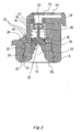
- Fig. 1 shows a first embodiment of an ink cartridge according to the present invention.
- an ink cartridge 2 has an ink chamber 4 for containing ink, and an ink supply port 6 designed to establish an ink communication with the ink chamber 4.
- the ink cartridge 2 is also provided with a packing member 8 disposed within the ink supply port 6, and a valve member 10 located between the ink chamber 4 and the packing member 8.
- the valve member 10 is always urged toward the packing member 8 by an elastic force of a compression spring 12.
- the packing member 8 is made of an elastic material such as a rubber or a plastic.
- the ink chamber 4 accommodates therein a porous member 5 which absorbs ink.
- ink is retained in the ink chamber in stable without splashing, even when the ink cartridge mounted on a carriage of a printing apparatus moves in reciprocate at a high speed.
- the ink chamber 4 is always depressurized.
- Fig. 1 shows a part of the printing apparatus.
- the printing apparatus has a print head 102 fixed on the carriage, not shown in the drawings, a tapered ink supply needle 104 designed to establish a fluid communication with the print head 102, and an ink cartridge holder 106.
- the ink cartridge 2 is mounted on the ink cartridge holder 106 of the printing apparatus in such a way that the ink supply port 6 faces the ink supply needle 104 of the printing apparatus.
- the packing member 8 in the ink supply port 6 fits with the ink supply needle 104.
- the ink is then introduced from the ink chamber 4 to the print head 102 through holes formed in the tip end of the ink supply needle 104.
- Fig. 2 is an enlarged cross sectional view showing the ink cartridge 2.
- the ink supply port 6 is provided with an external opening 14 coupling to the ink supply needle 104 of the printing apparatus, and an internal opening 16 opening to the ink chamber 4.
- the packing member 8 is press-fitted in the ink supply port 6.
- the packing member 8 has a protruding portion 20 on its outside surface, fitting with a concave 22 formed on the side wall of the ink supply port 6, in order to have the packing member 8 retained in the ink supply port 6.
- the protruding portion 20 of the packing member 8 seals with the concave 22 of the ink supply port 6. Thus, ink does not leak from the ink supply port 6.
- the packing member 8 is made of an elastic material such as a rubber material including a silicon rubber, a chloroprene rubber, a butyl rubber, a ethylene-propylene rubber, a nitrile rubber, and an elastmer material.
- the packing member 8 is provided, if desired, with a lubricant coat at areas with which the ink supply needle 104 contacts, in order to smoothly receive the ink supply needle 104.
- the lubricant coat consists of a silicon resin or a fluorocarbon resin.
- the packing member 8 faces the ink chamber 4. This surface of the packing member is formed with a cylindrical recess 30 having a diameter compatible to receipt of a part of the valve device, which will be explained in detail hereinbelow.
- the packing member 8 has a hole 32 defined in the center thereof, capable of receiving the ink supply needle 104 formed in the cylindrical recess 30, having a diameter smaller than the diameter of the cylindrical recess 30, thereby to form an ink channel.
- the hole 32 of the packing member 8 expands and seals the ink supply needle 104 of the printing apparatus, when the ink supply needle 104 is inserted into the hole 32.
- the packing member 8 is formed with a protruding rim 34 surrounding the hole 32 formed in the above-mentioned surface of the packing member 8.
- the packing member 8 has a second surface facing the external opening 14, with a first tapered portion 24 and a second tapered portion 26. Each tapered portion on the second surface is tapered from the external opening 14 toward the ink chamber 4 for the purpose of guiding the ink supply needle 104 of the printing apparatus.
- the packing member 8 is also provided with a fitting portion 28 formed on the second surface, to fit with the ink supply needle 104 of the printing apparatus.
- the packing member 8 is press-fitted in the ink supply port 6 and defines an ink introducing chamber 36 within the ink supply port 6.
- the ink introducing chamber 36 is an area defined between the packing member 8 and the ink chamber 4.
- the valve member 4 is received in the ink introducing chamber 36.
- the ink introducing chamber 36 has a cylindrical guide unit 38 having a through bore 38a.
- the guide unit 38 receives a part of the valve member 10 in order to guide the valve member 10.
- the guide unit 38 contacts with the part of the valve member 10 necessary to have the valve member 10 moved vertically with respect to the packing member 8.
- the valve member 10 is always urged by a compression spring 12 toward the packing member 8, to contact with the packing member for selectively closing the ink channel of the packing member 8.
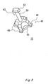
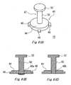
- Fig. 3 shows an embodiment of the valve member 10.
- the valve member 10 has a valve body 40 contacting with the packing member 8, and a guide body 42 for guiding the valve body 40.
- the guide body 42 helps the valve body 40 to move vertically with respect to the packing member, when the valve member 10 is received in the ink introducing chamber 38.
- the valve body 40 has a sealing portion 44 for sealing the ink channel of the packing member 8 when the valve body 40 contacts with the packing member 8, a spring support structure 46 for supporting the compression spring 12, and an ink channel 48 suitable for the passage of ink when the valve body comes out of contact with the packing member by the ink supply needle of the printing apparatus.
- the sealing portion 44 is substantially flat.
- a part of the ink channel 48 is formed by cutting off the sealing portion 44.
- the guide body 42 has an axial portion 50 connecting to the valve body 40, and a guide block 52 formed at an end of the axial portion 50 opposite to the valve body 40.
- the guide block 52 is slidably received in the guide unit 38.
- the guide block 52 has a diameter larger than a diameter of the through bore 38a of the guide unit 38.
- the guide block 52 of the valve member 10 cooperates with the guide unit 38, to have the valve body 10 move vertically with respect to the packing member 8.
- the print head 102 is of an ink jet type print head normally referred to as a piezoelectric type print head.
- a piezoelectric type print head by driving a piezoelectric transducer a pressure chamber is expanded to lead ink in, and applies a pressure to ink to eject ink droplets out of the print head. It is necessary to dissolve, during manufacturing, any bubbles in the ink within the cartridge of this type of print head, because bubbles in the ink may cause inadequate compression of the pressure chamber so that ink droplets do not eject as they are designed.
- the ink is injected in the ink cartridge at a negative pressure of minus 1 atom of the atmospheric pressure (1.033kg / per square meter) when the ink cartridge is manufactured.
- the compression coil spring is designed to be strong enough to urge the valve member 10 toward the packing member 8 in order to have the valve member 10 form a contact with the packing member 8, even under the low pressure condition.
- the internal opening 16 formed at the side of the ink supply port 6 opening to the ink chamber 4 has a dimension larger than the dimension of the ink introducing chamber 36 in which the valve member 10 is accommodated. The result is, ink can smoothly be introduced to the ink introducing chamber 36, and flown to the ink supply port 6.
- a filter 54 is provided between the internal opening 15 of the ink supply port 6 and the ink chamber 4 of the ink cartridge. The filter 54 collects dust or foreign particles existing in the ink chamber 4. Furthermore, as the filter 54 has a dimension same as that of the internal opening 16, ink passes smoothly through the filter 54.
- a sealing film 56 which is designed to be penetrated by the ink supply needle may be adhered to cover the external opening 14 for sealing the ink supply port 6 prior to use.
- the sealing film 56 serves to close the ink supply port 6 and also to retain the packing member 8 at the external opening 14 of the ink supply port 6.
- valve body 40 when the ink cartridge is not mounted on the printing apparatus, the valve body 40 is urged toward the packing member 8 by the compression spring 12. The sealing portion 44 contacts with the protruding rim 34 surrounding the hole 32 of the packing member 8. Thus, the ink introducing chamber 36 is closed by the packing member 8 and the valve member 10.
- the external opening 14 of the ink supply port 6 is adjusted to fit the ink supply needle 104 to have the ink cartridge 2 depressed in the ink cartridge holder 106 of the printing apparatus.
- the tapered ink supply needle 104 then penetrates the sealing film 56, to be inserted into the fitting portion 28 whilst being guided by the first and second tapered portions 24 and 26 of the packing member 8.
- the tapered ink supply needle 104 is smoothly inserted into the hole 32 of the packing member 8. This causes the hole 32 to expand, and the fitting portion 28 of the packing member 8 seals the ink supply needle 104.
- the ink supply needle 104 urges the flat sealing portion 44 of the valve member 10.
- the valve member 10 moves toward the ink chamber 4 against the elastic force of the compression spring 12.
- the ink supply needle 104 becomes held in communication with the ink introducing chamber 36 via the hole formed in the tip end of the ink supply needle 104, and thus allows ink to flow to the print head 102.
- the ink supply needle 104 When the cartridge 2 is removed from the printing apparatus, the ink supply needle 104 is detached from the packing member 8. The result is, the valve member 10 is urged toward the packing member 8 by the elastic force of the compression spring 12. The sealing portion 44 of the valve member 10 closes the ink channel of the packing member 8 when the ink supply needle 104 is completely detached from the packing member 8. It means that when the ink supply needle 104 is released from the fitting portion 28 of the packing member 8, at the same time, the sealing portion 44 of the valve body 40 is urged toward the packing member 8 to close the ink introducing chamber 36.
- the packing member 8 may not be formed with a protruding rim 34 surrounding the hole 32 of the packing member 8, to have the valve body 40 contact with the surface of the cylindrical recess 30.
- Fig. 5(B) shows the packing member 8 and the ink supply needle 104 of the printing apparatus, when the external opening 14 of the ink cartridge 2 is designed to have a size allowing the ink supply needle 104 of the ink cartridge 2 to be pushed into the ink cartridge holder 106. In this case, the same operation as explained with reference to Figs. 4(A) and 4(B) can be obtained.
- the sealed connection between the packing member 3 and the valve member 10 can be ensured, because the contacting surface between the valve body 40 and the cylindrical recess 30 of the packing member 8 is large.
- the packing member 8 may have a tapered portion 58 larger than the tapered ink supply needle 104 at the second surface. Furthermore, as shown in Figs. 7(A) and 7(B), the packing member 8 may have a single tapered portion 60 tapered from the external opening 14 to the hole 32 of the packing member 8. In these cases, when the ink cartridge 2 is pushed into the ink cartridge holder 106 to have the ink supply needle 104 inserted into the hole 32 of the packing member 8, the tapered portion 58 and the tapered portion 60 each fit with the ink supply needle 104. The same operation as explained with reference to Figs. 4(A) and 4(B) can also be obtained in these cases.
- the sealed connection between the packing member 8 and the valve member 10 can be ensured, because the contacting surface between the valve body 40 and the cylindrical recess 30 of the packing member 8 is large.
- the sealed connection between the packing member 8 and the valve member 10 can be ensured because the fitting force between the tapered portion 60 and the ink supply needle 104 is strong.
- the packing member 8 shown in this embodiment is formed as one unit, the packing member 8 may be separately formed as comprising two units; one of which is a part with which the valve member 10 contacts and the other of which is a part with which the ink supply needle 104 fits.
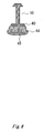
- Fig. 8 shows another example of the valve member 10 having a surface at the sealing portion 44, facing the packing member 8, formed with a spherical surface Q5 to contact with the tip end of the ink supply needle 104.
- Fig. 9 (A) shows another embodiment of the valve member 10.
- the components of the valve member 10 shown in Fig. 9 (A) are formed separately from one another, including a valve body 40 to form a contact with the packing member 8, and a guide body 42 for guiding the valve body 40 vertically with respect to the packing member 8.
- the valve body 40 has a sealing portion 44 and a plurality of, at least three, spring support structure 46 around the sealing portion 44.
- the guide body 42 is formed as one piece, with an axial portion 50 being connected to the valve body 40 and a guide block 52.
- the guide block 52 guides the valve body 40 vertically with respect to the packing member 8, in cooperation with the guide unit 38 of the ink introducing chamber 36.
- the end of the axial portion 50 of the guide body 42, opposite to the guide block 52 is secured to the sealing portion 44 of the valve body 40, to assemble the valve member 10.
- the valve member 10 is incorporated in the ink supply port 6 by inserting the guide body 42 from the internal opening 16, to be passed through the guide unit 38 of the ink introducing chamber 36, entering the compression spring 12 from the internal opening 16 to be placed around the ink introducing chamber 36, and fixing the valve body 40 to the guide body 42.
- the valve body 40 and the guide body 42 may be fixed to each other by providing a fixing hole 40a to the valve body 40.
- the guide body 42 is inserted into the fixing hole 40a-of the valve body 40, and fixed by heat welding or adhesive as shown in Fig. 9(B).
- the valve body 40 and the guide body 42 may be fixed to each other by forming a fixing hole having a thread to the valve body 40, forming a thread to the axial portion 50, and connecting these parts to each other as shown in Fig. 9(C).
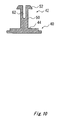
- Fig. 10 shows another embodiment of the valve member 10.
- the valve member 10 has a valve body 40 and a guide body 42.
- the guide body 42 is provided with an axial portion 50 and a guide block 52.
- the axial portion 50 and the guide block 52 of the guide body 42 are formed as one unit.
- the guide body 42 is made of an elastic material such as a plastic and formed with a groove 62 extending from the guide block 52 through the axial portion 50.
- the valve body 40 may be made of the same elastic material, such as a plastic, and formed as one unit with the guide body 42.
- the ink supply needle 104 contacts with and urges the valve body 40.
- the valve body 40 may therefore be made of a soft and flexible material which does not damage the tip end of the ink supply needle 104.
- the guide block 52 of the guide body 42 may be tapered toward the valve body 40 as shown in Fig. 10.
- the valve member 10 is incorporated in the ink supply port 6 by entering the compression spring 12 from the internal opening 16 to be placed around the ink introducing chamber 36.
- the edge of the guide body 42 having the groove 62 is pushed into the through bore 38a of the guide unit 38.
- the guide block 52 has a groove 62 which allows the guide block 52 to be buckled as it passes through the through bore 38, and then spreads to be retained in the guide unit 38.
- the valve member 10 can be formed as one unit, therefore, the number of parts and working process are reduced.
- the guide block 52 of the valve member 10 has a groove 62.
- the guide unit 38 may be formed to allow splitting into a plurality of strips for elastically accepting the guide block 52 of the valve device.
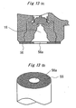
- valve member 10 As the valve member 10 is contained in the ink introducing chamber 36, the valve member 10 needs to be manufactured in a small size. This leads that ink is not provided smoothly to the print head even when the ink channel is open. Therefore, as shown in Fig. 11, the valve member 10 is formed with a depression 44a and the penetrating portion 44b formed at the sealing portion 44 of the valve body 40 to allow ink to smoothly pass therethrough.
- the penetrating portion 44b is formed at the outside of the sealing portion so that the sealing portion 44 can close the hole 32 of the packing member 8 when the sealing portion 44 contacts with the packing member 8.
- the valve member 10 preferably has a plurality of these depressions 44a and penetrating portions 44b in order to pass ink from the ink chamber 4 to the print head smoothly.
- the ink introducing chamber 36 may have a depression 36a formed at the side wall of the ink introducing chamber 36.
- the depression 36a is formed from the upper point where the sealing portion 44 of the valve body 40 positions when the valve member 10 is not urged by the ink supply needle 104 to the point where the sealing portion 44 of the valve body 40 positions when the valve member 10 is urged by the ink supply needle 104 in Fig. 12.
- ink is provided smoothly to the print head through the depression 36a.
- the valve member 10 having a depression 44a as shown in Fig. 11 may be used with this ink introducing chamber 36 as shown in Fig. 12.
- the ink of the ink supply port 6 is sealed by the connection between the packing member 8 and the valve member 10.
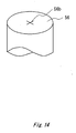
- the sealing film 56 provided at the external opening 14 may be formed with a hole 56a which enables the ink supply needle 104 to pass through.
- the hole may-be formed by cutting the film in a cross shape as shown in Fig. 14. By making the hole, the ink supply needle smoothly pass through the film.
- the ink cartridge 2 may have a protruding portion 14a protruding from the external opening 14 toward the center thereof, as a retainer for retaining the packing member 8 at the external opening 14 of the ink supply port 6.
- the protruding portion can be simply formed by protruding a part of the external opening 14. The result is, the number of parts or components and manufacturing process are reduced.
- the external opening 14 may have a retreating opening 14b as shown in Fig. 16(A) and 16(B).
- the sealing film 56 is attached at the external opening 14 to retain the packing member 8 at the external opening 14.
- the ink supply port 6 is open to the external ambient air, therefore, the packing member 8 and the valve member 10 are not influenced by the expansion and the contraction of the air in the ink supply port 6.
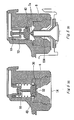
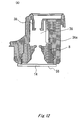
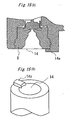
- Fig. 17(A) 17(B) and 17(C) show another embodiment of the ink cartridge according to the present invention.
- a packing member 8 and a valve member 10 are provided in the ink supply port 6 in the same way as the embodiment shown in Fig. 2.
- the ink supply port 6 has an external opening 14 designed to face the ink supply needle 104 of the printing apparatus, and an internal opening 16 designed to open to the ink chamber 4.
- the parts and components having the same symbols as Fig. 2 and not specifically mentioned here have the same operations and effects as those shown in Fig. 2.
- the packing member 8 has a first surface facing the ink chamber 4 with a protruding portion 8a protruding from the fitting portion 28 toward the ink chamber 4.
- the first surface has a hole 18a, whose diameter is smaller than the diameter of the needle of the recording apparatus.
- the packing member 8 has a second surface facing the external opening 14 with a first tapered portion 24 and a second tapered portion 26 each tapered from the external opening 14 toward the ink chamber 4 at the second surface. The function of this is to guide the ink supply needle 104 of the printing apparatus.
- the packing member 8 further has a fitting portion 28 to fit with the ink supply needle 104 of the printing apparatus.
- the valve member 10 has a valve body 40 and a guide body 42.
- the valve body 40 has a sealing portion 44 and a spring support structure 46.
- the guide body 42 has an axial portion 50 and a guide block 52.
- the sealing portion 44 of the valve body 40 has a surface facing the packing member 8 formed with a protruding portion 45b to contact with the tip end of the ink supply needle 104.
- the protruding portion 45b has a size compatible with the hole 18a of the protruding portion 8a of the packing member 8.
- the valve member 10 is received in the guide unit 38 of the ink introducing chamber 38, to be moved vertically with respect to the packing member 8.
- the protruding portion 45b has a height that permits it to form a contact with the tip end of the ink supply needle 104 at the time when the ink supply needle 104 forms a sealed connection with the packing member 8 as shown in Fig. 17(B). It means that the valve member 10 is urged by the ink supply needle 104 to open the ink supply port 6 at the time when the ink supply needle 104 and the packing member 8 form a sealed connection with each other. Thus, undesirable air or bubble do not enter the ink supply port 6.
- the tip end of the ink supply needle 104 contacts the protruding portion 45b of the sealing portion 44 at the time when the tapered ink supply needle 104 fits with the packing member 8. This forms a sealed connection between them, by mounting the ink cartridge 2 on the printing apparatus.
- the ink supply needle 104 fits into the fitting portion 34 of the packing member and is inserted into the hole 18a of the protruding portion 8a of the packing member 8 whilst forcing out any air. Then, the ink can be provided to the print head 102.
- the valve member 10 is forcibly separated from the packing member 8 when the ink supply needle 104 is inserted into the ink supply port 6 whilst forming a sealed connection with the packing member 8 as described above. Therefore, the air compressed by the ink supply needle when it is inserting in the ink supply port does not enter the ink supply port 6 and the ink supply needle 104.
- the ink supply needle 104 When, on the other hand, the cartridge 2 is removed from the printing apparatus, the ink supply needle 104 is detached from the packing member 8.
- the valve member 10 is urged toward the packing member 8 by the elastic force of the compression spring 12.
- the protruding portion 45b of the sealing portion 44 of the valve member 10 is accepted into the hole 18a of the packing member 8, whilst the ink supply needle 104 be detached from the packing member 8.
- the sealing portion 44 of the valve member 10 forms a contact with the protruding portion 8a of the packing member 8. This closes the ink introducing chamber 36 when the ink supply needle 104 is almost detached from the packing member 8 but is still forming the sealed connection with the fitting portion 28 of the packing member 8.
- the ink does not leak from, and undesirable air or bubble does not enter the ink cartridge through the external opening 14 of the ink supply port.
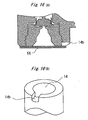
- Fig. 18(A) 18(B) and 18(C) show another embodiment of the ink cartridge according to the present invention.
- the ink cartridge has a packing member 8.
- the packing member 8 has a protruding portion 8a and a hole 18a formed at the protruding portion 8a of the packing member 8 in the same way as that shown in Figs. Fig. 17(A) 17(B) and 17(C).
- the valve member 10 has a valve body 40 and a guide body 42 .
- the valve body 40 has a sealing portion 44 and a spring support structure 46.
- the guide body 42 has an axial portion 50 and a guide block 52.
- the sealing portion 44 of the valve body 40 has a surface facing the packing member 8, formed with a convex surface 45 .
- the convex surface 45 is a spherical surface .
- the spherical surface of the valve body 40 has a diameter of curvature larger than a diameter of a widest part of the valve body 40.
- Fig. 19(A) shows an enlarged cross sectional view of the valve member 10 having a spherical convex surface 45.
- the convex surface 45 of the sealing portion 44 of the valve body 40 is like a part of a sphere having a diameter "R".
- the diameter R of the sphere is larger than the length "L" of the axial portion 50 of the valve member 10.
- the tip end of the ink supply needle 104 contacts the spherical convex 45 of the sealing portion 44. This occurs at the time when the tapered ink supply needle 104 fits with the packing member 8, to form the sealed connection with each other when mounting the ink cartridge 2 on the printing apparatus.
- the ink supply needle 104 When the ink cartridge 2 is further pushed toward the printing apparatus, the ink supply needle 104 is guided by the tapered portion 58 to contact with the center of the convex surface 45 of the valve member 10. Under this condition, the ink supply needle 104 is inserted into the hole 18a of the protruding portion 8a of the packing member 8.
- valve member 10 is forced to come out of contact with the packing member 8 when the ink supply needle 104 is inserted into the ink supply port 6 whilst forming the sealed connection with the packing member 8 as described above . Therefore, the air compressed by the ink supply needle does not enter the ink supply port 6.
- the ink supply needle 104 contacts with the center of the spherical convex surface 45 having a large diameter of curvature and the valve member 10 is regulated by its axial portion 50, therefore, contact between the valve member 10 and the ink supply needle 104 is ensured.
- the ink supply needle 104 When, on the other hand, the cartridge 2 is removed from the printing apparatus, the ink supply needle 104 is detached from the packing member 8.
- the valve member 10 is urged toward the packing member 8 by the elastic force of the compression spring 12.
- the convex surface 45 of the sealing portion 44 of the valve member 10 forms a contact with the protruding portion 8a of the packing member 8, to close the ink introducing chamber 36.
- the ink does not leak from, and undesirable air bubbles do not enter the external opening 14.
- the sealing portion 44 has the spherical convex surface 45, the sealed connection between the packing member 8 and the valve member 10 is ensured even when the position of the valve member 10 varies.
- the spherical convex surface 45 of the valve member 10 may have a flat surface 45c having a diameter smaller than the diameter of the hole 18a of the protruding portion 8a of the packing member 8 as shown in Fig. 19(B). In this case, the contacting surface between the ink supply needle 104 and the valve member 10 is large, to enforce the contact therebetween without reducing the sealed connection between the ink supply needle 104 and the packing member 8.
- the closing surface 44 of the valve member 10 may be formed as a conical shape 45d having its point removed, to leave a flat surface 45c remained. In this case, the contact between the ink supply needle 104 and the valve member 10 is enforced as well, without reducing the sealed connection between the ink supply needle 104 and the packing member 8.
- the elastic member may be an extension spring 64 as shown in Fig. 20.
- the extension spring 64 is fixed to the ink cartridge 2 at an end by the packing member 8 to have the other end of the extension spring 64 contact with the valve member 10.
- the valve member 10 is forced toward the packing member 10.
- the valve member does not need to have a spring support structure 46, and the ink cartridge 2 does not need to have a guide unit 38 in the ink introducing chamber 36. The result is, that the structure of the ink cartridge 2 can be simplified, thus, the manufacturing process can be reduced.
- Figs. 21 and 22 shows another example of the valve device according to the present invention.
- the valve device 70 has a valve body 72 to form contact with the packing member 8, and an elastic support portion 74 for supporting the valve body 72 in order to have the valve body 72 contact with the packing member 8.
- the elastic support portion 74 is made of an elastic material such as a hard rubber, a plastic material having a high elastic modulus, or an elastomer material.
- the elastic support portion 74 is capable of bending when the ink supply needle 104 fits with the packing member, to urge the valve body 72 of the valve device 70.
- the valve body 72 and the elastic support portion 74 may be separately formed, or may be formed as one unit.
- the elastic support portion 74 of the valve device 70 urges the valve body 72 toward the packing member 8. At the same time, the valve body 72 contacts with the packing member 8, and guides the valve member vertically with respect to the packing member 8. Therefore, the number of parts can be reduced.
- the valve device 70 may have a plurality of elastic support portions 74, for example, three in Fig. 21, or only one elastic support portion 74 as shown in Fig. 22.
- FIG. 23(A) and 23(B) show another embodiment of the valve device according to the present invention.
- the valve device 80 has a valve member 82 to form a contact with the packing member 8 and an elastic member 84 for urging the valve member 82 toward the packing member 8 in order to have the valve member 82 contact with the packing member 8.
- the elastic member 84 is made of a polymeric elastomer or a rubber capable of expanding.
- the valve body 32 is urged to selectively contact with the packing member 8 by the elastic member 84 connected to the cylindrical recess 30 of the packing member 8 in the embodiment shown in Fig. 23(A).
- the valve body 82 is urged by the ink supply needle 104 of the printing apparatus toward the ink chamber, to open the valve device 80.
- the ink is provided from the ink chamber to the print head 102 of the printing apparatus through the hole of the ink supply needle 104.
- valve body 82 A part of the valve body 82 is fixed at the packing member 8 as shown in Figs. 24(A) and 24(B).
- the valve body 82 is urged to contact with the packing member 8 by the elastic member 84 in this case as well.
- the valve body 84 is urged toward the ink chamber by the ink supply needle 104, to open the hole of the packing member 8.
- the ink is then provided from the ink chamber to the print head 102 of the printing apparatus through the hole of the ink supply needle 104.
- the valve device 80 may be formed as one unit with the packing member 8. It means that the valve device 80 is fixed to the packing member 8 as its part. Thus, the number of parts and manufacturing process can be reduced.
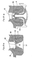
- the valve body 40 of the valve member 10 may have a surface facing the packing member provided with a notch as shown in Figs. 25(A) to 25(D).
- the notch 40c of the valve body 40 shown in Figs. 25(A) and 25(B) has an angle the same as that of the tapered ink supply needle 104.
- the notch 40d of the valve body 40 shown in Figs. 25(C) and 25(D) has an angle smaller than that of the tapered ink supply needle 104.
- the packing member 8 may have two fitting portions, a first fitting position 28a for fitting the ink supply needle of the printing apparatus when the ink supply needle 104 is inserted from the external opening 14, and a second fitting position 28b for fitting the ink supply needle 104 when the ink supply needle 104 is further inserted toward the ink chamber 4.
- each of the fitting portions 28a and 28b fits with the ink supply needle 104.
- the sealed connection between the packing member and the ink supply needle 104 can be enforced.
- Each of the fitting portions 28a and 28b may be formed with or without a hole.
- the fitting portion 28a closer to the external opening 14 is not formed with a hole and is sealed initially prior to use.
- the number of parts can be reduced because the ink cartridge does not have a sealing film to seal the supply port 6 prior to use.
- the fitting portion 28a is formed as tapered as shown in Fig. 26, so the ink supply needle 104 can smoothly penetrate the sealed fitting portion 28a.
- the ink cartridge according to the present invention may be used as an off-carriage type ink cartridge which is mounted on a fixed part of the body of the printer and connected to the print head which is mounted on the carriage, through a flexible ink supply tube.
- the ink cartridge according to the present invention may also be applied to a printing apparatus in which a heating element is used as a pressurizing means not only to the printing apparatus in which the piezoelectric transducer is used as a pressurizing means of the print head.
- an ink cartridge and an ink supply system are capable of closing the ink supply channel when it is not mounted on the printing apparatus and capable of opening the ink supply channel to provide ink to the print head when it is mounted on the printing apparatus.
- a printing apparatus employing the ink cartridge or the ink supply system is also provided by the present invention.
- Ink can be supplied from the ink supply port to the ink supply needle without having air or bubble enter the ink supply port because the valve device is urged by the ink supply needle of the printing apparatus to open the ink channel under a state where the ink supply needle is sealed by the packing member.
- the ink supply port can be sealed without having air or bubble enter the ink supply port because the valve device comes to close the ink channel of the packing member before the ink supply needle of the printing apparatus is completely detached from the packing member.
- the ink supply needle can be smoothly inserted in the packing member because the packing member is made of an elastic material and provided with a lubricant coat at least at an area with which the ink supply needle contacts.
- the packing member can seal the ink supply needle because the packing member includes a tapered portion or a fitting portion fitting the ink supply needle.
- the ink supply needle can securely contact with the valve device, because the valve device includes a substantially flat surface with which the ink supply needle contacts.
- valve body can be moved substantially vertically with respect to the packing member because the valve device includes a guide body for guiding the valve body to slide substantially vertically with respect to the packing member.
- manufacturing process can be simplified and reduced because the number of parts or components necessary for assembling the ink cartridge according to the present invention is reduced.
Landscapes
- Ink Jet (AREA)
- Inks, Pencil-Leads, Or Crayons (AREA)
- Pens And Brushes (AREA)
- Ink Jet Recording Methods And Recording Media Thereof (AREA)
- Particle Formation And Scattering Control In Inkjet Printers (AREA)
Claims (17)
- Tintentank (2) für eine Druckvorrichtung, die Tinte zu einem Druckkopf (102) über eine konisch zulaufende Tintenzufuhrnadel(104) liefert und lösbar an dem Druckkopf angebracht ist, umfassend:eine Tintenkammer (4) zum Enthalten von Tinte;eine Tintenaustrittsöffnung (6) zum Zuführen von Tinte von der Tintenkammer zu dem Druckkopf der Druckvorrichtung, wobei die Tintenaustrittsöffnung eine äußere Öffnung (14) aufweist;ein in der Tintenaustrittsöffnung vorgesehenes Dichtelement (8), das einen Tintenkanal zum Ermöglichen einer Strömung von Tinte bildet, wobei das Dichtelement die Tintenzufuhrnadel der Druckvorrichtung durch ein Passung dazwischen abdichtet; undeine in der Tintenaustrittsöffnung enthaltene Ventilvorrichtung (10, 12, 64, 70 und 80), die den Tintenkanal durch elastisches Anliegen an dem Dichtelement schließt, wobei die Ventilvorrichtung selektiv den Tintenkanal in Verbindung mit der Tintenzufuhrnadel öffnet und schließt, wobei die Ventilvorrichtung (10) aufweist:einen Ventilkörper (40), der das Dichtelement berührt und durch die Tintenzufuhrnadel der Druckvorrichtung beaufschlagt wird, um den Tintenkanal zu öffnen, wenn der Tintentank an der Druckvorrichtung montiert ist; dadurch gekennzeichnet, dass die Ventilvorrichtung ferner aufweisteinen Führungskörper (42), umfassend:einen axialen Abschnitt (50), der mit dem Ventilkörper verbunden ist; undeinen Führungsblock (52), der an einem Ende des axialen Abschnitts gegenüberliegend zu dem Ventilkörper gebildet ist, wobei der Führungsblock den Ventilkörper führt, um im wesentlichen vertikal in Bezug auf das Dichtelement zu gleiten.
- Tintentank nach Anspruch 1, bei welchem der axiale Abschnitt (50) des Führungskörpers (42) als eine Einheit mit dem Ventilkörper (40) gebildet ist.
- Tintentank nach Anspruch 1, ferner umfassend eine Führungseinheit (38), die in der Tintenaustrittsöffnung (60) vorgesehen ist, um den Führungsblock (52) des Führungskörpers (42) zu empfangen.
- Tintentank nach Anspruch 2, bei welchem der Ventilkörper und der Führungskörper als eine Einheit miteinander gebildet sind.
- Tintentank nach Anspruch 1, bei welchem der Führungskörper mit einer Nut (62) gebildet ist, die sich von dem Führungsblock durch den axialen Abschnitt (50) erstreckt.
- Tintentank nach Anspruch 1, bei welchem der Ventilkörper und der Führungskörper separat gebildet und aneinander durch Befestigungsmittel befestigt sind.
- Tintentank (2) nach Anspruch 1, bei welchem der Ventilkörper der Ventilvorrichtung eine dem Dichtelement zugewandte Oberfläche und ein von der Oberfläche hervorstehendes und ein Spitzenende der Tintenzufuhrnadel berührendes Element (45b) aufweist.
- Tintentank (2) nach Anspruch 1, bei welchem der Ventilkörper der Ventilvorrichtung eine dem Dichtelement zugewandte Oberfläche aufweist, die mit einer Kerbe (40c und 40d) ausgestattet ist.
- Tintentank (2) nach Anspruch 8, bei welchem die Tintenzufuhrnadel konisch zulaufend ist und die Kerbe (40c) des Ventilkörpers einen konisch zulaufenden Winkel besitzt, welcher derselbe wie derjenige der konisch zulaufenden Tintenzufuhrnadel.
- Tintentank (2) nach Anspruch 8, bei welchem die Tintenzufuhrnadel konisch zulaufend ist und die Kerbe (40d) des Ventilkörpers einen konisch zulaufenden Winkel besitzt, der geringer ist als derjenige der konisch zulaufenden Tintenzufuhrnadel.
- Tintentank (2) nach Anspruch 1, bei welchem der Ventilkörper einen durchdringenden Abschnitt (44b) aufweist, durch den Tinte passiert.
- Tintentank (2) nach Anspruch 11, bei welchem der Ventilkörper ferner einen Dichtabschnitt (44) zum Abdichten des Tintenkanals des Dichtelements (8) aufweist, wenn der Ventilkörper (40) das Dichtelement (8) berührt, und der durchdringende Abschnitt ist außerhalb des Dichtabschnitt (44) gebildet.
- Tintentank (2) nach Anspruch 11, bei welchem der Ventilkörper ferner eine Vertiefung (44a) aufweist, die an dem durchdringenden Abschnitt (44b) gebildet ist.
- Tintentank (2) nach Anspruch 12, bei welchem der Ventilkörper ferner mindestens eine Halterungsstruktur (46) zum Haltern eines elastischen Element (12 und 64) zum elastischen Zwängen des Ventilkörpers gegen das Dichtelement aufweist, und die Halterungsstruktur steht nach außen von dem Dichtabschnitt (44) hervor.
- Tintentank (2) nach Anspruch 1, bei welchem der Ventilkörper ferner mindestens eine Halterungsstruktur (46) zum Haltern eines elastischen Elements (12 und 64) zum elastischen Zwängen des Ventilkörpers gegen das Dichtelement aufweist, und die Halterungsstruktur steht nach außerhalb von einem Hauptteil des Ventilkörpers hervor.
- Tintentank (2) nach Anspruch 6, bei welchem die Befestigungsmittel Wärmeschweißen oder Haftmittel aufweisen.
- Tintentank (2) nach Anspruch 6, bei welchem die Befestigungsmittel ein Befestigungsloch mit einem Gewinde, das in dem Ventilkörper (40) gebildet ist, und ein an dem axialen Abschnitt (50) gebildetes Gewinde aufweisen.
Applications Claiming Priority (8)
| Application Number | Priority Date | Filing Date | Title |
|---|---|---|---|
| JP32011398 | 1998-11-11 | ||
| JP32011398 | 1998-11-11 | ||
| JP5667699 | 1999-03-04 | ||
| JP5667699 | 1999-03-04 | ||
| JP22843099 | 1999-08-12 | ||
| JP22843099 | 1999-08-12 | ||
| EP03016578A EP1403062B8 (de) | 1998-11-11 | 1999-11-11 | Tintenstrahlaufzeichnungsgerät und Tintenpatrone |
| EP99122003A EP1000753B1 (de) | 1998-11-11 | 1999-11-11 | Tintenstrahldruckvorrichtung und Tintenpatrone |
Related Parent Applications (1)
| Application Number | Title | Priority Date | Filing Date |
|---|---|---|---|
| EP03016578A Division EP1403062B8 (de) | 1998-11-11 | 1999-11-11 | Tintenstrahlaufzeichnungsgerät und Tintenpatrone |
Publications (3)
| Publication Number | Publication Date |
|---|---|
| EP1452323A2 EP1452323A2 (de) | 2004-09-01 |
| EP1452323A3 EP1452323A3 (de) | 2004-11-17 |
| EP1452323B1 true EP1452323B1 (de) | 2006-08-16 |
Family
ID=27295994
Family Applications (3)
| Application Number | Title | Priority Date | Filing Date |
|---|---|---|---|
| EP99122003A Expired - Lifetime EP1000753B1 (de) | 1998-11-11 | 1999-11-11 | Tintenstrahldruckvorrichtung und Tintenpatrone |
| EP04011374A Expired - Lifetime EP1452323B1 (de) | 1998-11-11 | 1999-11-11 | Tintenpatrone |
| EP03016578A Expired - Lifetime EP1403062B8 (de) | 1998-11-11 | 1999-11-11 | Tintenstrahlaufzeichnungsgerät und Tintenpatrone |
Family Applications Before (1)
| Application Number | Title | Priority Date | Filing Date |
|---|---|---|---|
| EP99122003A Expired - Lifetime EP1000753B1 (de) | 1998-11-11 | 1999-11-11 | Tintenstrahldruckvorrichtung und Tintenpatrone |
Family Applications After (1)
| Application Number | Title | Priority Date | Filing Date |
|---|---|---|---|
| EP03016578A Expired - Lifetime EP1403062B8 (de) | 1998-11-11 | 1999-11-11 | Tintenstrahlaufzeichnungsgerät und Tintenpatrone |
Country Status (15)
| Country | Link |
|---|---|
| US (3) | US6786581B1 (de) |
| EP (3) | EP1000753B1 (de) |
| JP (5) | JP2001113723A (de) |
| KR (1) | KR100362908B1 (de) |
| CN (3) | CN1113753C (de) |
| AT (3) | ATE336380T1 (de) |
| CA (2) | CA2289244C (de) |
| DE (3) | DE69932867T2 (de) |
| DK (2) | DK1403062T3 (de) |
| ES (3) | ES2270222T3 (de) |
| HK (3) | HK1027781A1 (de) |
| MY (2) | MY138451A (de) |
| PT (2) | PT1452323E (de) |
| SG (2) | SG118189A1 (de) |
| TW (1) | TW556668U (de) |
Families Citing this family (99)
| Publication number | Priority date | Publication date | Assignee | Title |
|---|---|---|---|---|
| JP2001113723A (ja) * | 1998-11-11 | 2001-04-24 | Seiko Epson Corp | インクジェット式記録装置及びインクカートリッジ |
| AU4823001A (en) | 2000-04-03 | 2001-10-30 | Unicorn Image Products Co Ltd | An ink cartridge and a method and device for filling the ink cartridge |
| US6935730B2 (en) | 2000-04-03 | 2005-08-30 | Unicorn Image Products Co. Ltd. Of Zhuhai | One-way valve, valve unit assembly, and ink cartridge using the same |
| JP2002079690A (ja) * | 2000-06-30 | 2002-03-19 | Seiko Epson Corp | 保守用カートリッジ、及びこのカートリッジを使用するインクジェット記録装置 |
| WO2002020270A1 (fr) * | 2000-07-31 | 2002-03-14 | Unicorn Image Products Co. Ltd. Of Zhuhai | Cartouche d'encre comprenant une piece d'etancheite au niveau de l'equipement de sortie d'encre |
| DE10100171B4 (de) * | 2001-01-04 | 2005-02-24 | Artech Gmbh Design + Production In Plastic | Durchstechbares Verschlusselement und Tintenbehälter mit durchstechbarem Verschlusselement |
| JP4193435B2 (ja) | 2002-07-23 | 2008-12-10 | ブラザー工業株式会社 | インクカートリッジ、および、そのインク充填方法 |
| US6651955B2 (en) * | 2001-07-30 | 2003-11-25 | Hewlett-Packard Development Company, L.P. | Elastomeric valve, and methods |
| WO2003037634A1 (fr) * | 2001-10-31 | 2003-05-08 | Print-Rite Unicorn Image Products Co. Ltd Of Zhuhai | Cartouche d'encre pour imprimante |
| DE10206696B4 (de) | 2002-02-18 | 2006-01-26 | Pelikan Hardcopy Production Ag | Tintenpatrone mit Ventil |
| ATE448269T1 (de) * | 2002-05-14 | 2009-11-15 | Shigenobu Hamano | Lösungsmittel zur behandlung von polystyrolharz und verfahren zur behandlung von polystyrolharz damit |
| WO2003103973A1 (ja) | 2002-06-11 | 2003-12-18 | セイコーエプソン株式会社 | インクカートリッジ |
| CN1277685C (zh) | 2002-12-10 | 2006-10-04 | 精工爱普生株式会社 | 液体盒 |
| JP3809828B2 (ja) | 2002-12-10 | 2006-08-16 | セイコーエプソン株式会社 | 液体カートリッジの製造方法 |
| JP3848298B2 (ja) * | 2003-05-22 | 2006-11-22 | キヤノン株式会社 | インクタンク |
| US7384133B2 (en) * | 2003-08-08 | 2008-06-10 | Seiko Epson Corporation | Liquid container capable of maintaining airtightness |
| GB2405683A (en) * | 2003-09-05 | 2005-03-09 | Comm Corp Ltd I | Valve for a cartridge |
| EP1520707B1 (de) | 2003-09-30 | 2007-08-15 | Brother Kogyo Kabushiki Kaisha | Tintenpatrone und Tintenstrahlaufzeichnungsgerät |
| US7334888B2 (en) * | 2003-11-25 | 2008-02-26 | Brother Kogyo Kabushiki Kaisha | Ink cartridge |
| US7278722B2 (en) * | 2003-11-25 | 2007-10-09 | Brother Kogyo Kabushiki Kaisha | Ink cartridge |
| JP4517659B2 (ja) * | 2003-11-25 | 2010-08-04 | ブラザー工業株式会社 | インクカートリッジ及び弁装置 |
| US7325913B2 (en) * | 2003-11-25 | 2008-02-05 | Brother Kogyo Kabushiki Kaisha | Ink cartridge |
| US7384136B2 (en) | 2003-11-25 | 2008-06-10 | Brother Kogyo Kabushiki Kaisha | Ink cartridge |
| US7334889B2 (en) * | 2003-11-25 | 2008-02-26 | Brother Kogyo Kabushiki Kaisha | Ink cartridge |
| US7367650B2 (en) * | 2004-01-21 | 2008-05-06 | Silverbrook Research Pty Ltd | Printhead chip having low aspect ratio ink supply channels |
| JP4513337B2 (ja) * | 2004-01-23 | 2010-07-28 | セイコーエプソン株式会社 | インクカートリッジ |
| TWI255233B (en) * | 2004-02-09 | 2006-05-21 | Brother Ind Ltd | Ink cartridge |
| CN100417525C (zh) * | 2004-02-09 | 2008-09-10 | 兄弟工业株式会社 | 墨盒 |
| US20050219281A1 (en) * | 2004-03-24 | 2005-10-06 | Takeo Seino | Attachment and liquid supplying |
| JP4321370B2 (ja) * | 2004-06-14 | 2009-08-26 | ブラザー工業株式会社 | インク充填方法 |
| JP4715115B2 (ja) * | 2004-06-23 | 2011-07-06 | ブラザー工業株式会社 | インク充填方法 |
| JP4172428B2 (ja) * | 2004-06-30 | 2008-10-29 | ブラザー工業株式会社 | インクカートリッジ |
| US20060023037A1 (en) * | 2004-07-30 | 2006-02-02 | Nu-Kote International, Inc. A Corporation Of Delaware | Clamping device for ink cartridges |
| JP4715169B2 (ja) * | 2004-11-18 | 2011-07-06 | ブラザー工業株式会社 | インクカートリッジのための保護部材 |
| JP4665500B2 (ja) * | 2004-12-13 | 2011-04-06 | ブラザー工業株式会社 | インクカートリッジ |
| US7455398B2 (en) * | 2004-12-13 | 2008-11-25 | Brother Kogyo Kabushiki Kaisha | Ink cartridge |
| CN2763042Y (zh) * | 2005-01-19 | 2006-03-08 | 珠海纳思达电子科技有限公司 | 一种喷墨打印机墨盒使用的密封件 |
| WO2006112208A1 (ja) * | 2005-03-30 | 2006-10-26 | Seiko Epson Corporation | 液体容器 |
| US7470011B2 (en) * | 2005-03-31 | 2008-12-30 | Canon Kabushiki Kaisha | Liquid discharging head cartridge |
| US7533976B2 (en) * | 2005-04-27 | 2009-05-19 | Hewlett-Packard Development Company, L.P. | Sealing component defining first, second, and third seals |
| JP4636251B2 (ja) * | 2005-08-10 | 2011-02-23 | ブラザー工業株式会社 | インクジェット記録装置 |
| US7575311B2 (en) * | 2005-09-29 | 2009-08-18 | Brother Kogyo Kabushiki Kaisha | Ink cartridge |
| EP1787817B1 (de) * | 2005-09-29 | 2008-08-27 | Brother Kogyo Kabushiki Kaisha | Tintenpatrone |
| US7578584B2 (en) * | 2005-09-29 | 2009-08-25 | Brother Kogyo Kabushiki Kaisha | Ink cartridge |
| US7591548B2 (en) * | 2005-09-29 | 2009-09-22 | Brother Kogyo Kabushiki Kaisha | Ink cartridge |
| US7635180B2 (en) * | 2005-09-29 | 2009-12-22 | Brother Kogyo Kabushiki Kaisha | Ink cartridge |
| JP4774896B2 (ja) * | 2005-09-29 | 2011-09-14 | ブラザー工業株式会社 | インクカートリッジ |
| JP4539517B2 (ja) * | 2005-09-29 | 2010-09-08 | ブラザー工業株式会社 | インクカートリッジ |
| JP4844070B2 (ja) * | 2005-09-29 | 2011-12-21 | ブラザー工業株式会社 | インクカートリッジ |
| US7669991B2 (en) * | 2005-09-29 | 2010-03-02 | Brother Kogyo Kabushiki Kaisha | Ink cartridge |
| US7357496B2 (en) * | 2005-12-05 | 2008-04-15 | Silverbrook Research Pty Ltd | Inkjet printhead assembly with resilient ink connectors |
| US7527353B2 (en) | 2005-12-05 | 2009-05-05 | Silverbrook Research Pty Ltd | Ink cartridge with sealed air inlet |
| US7556364B2 (en) | 2005-12-05 | 2009-07-07 | Silverbrook Research Pty Ltd | Ink cartridge with self sealing outlet valve |
| US7431440B2 (en) * | 2005-12-05 | 2008-10-07 | Silverbrook Research Pty Ltd | Ink reservoir with air bag |
| US7513603B2 (en) * | 2005-12-05 | 2009-04-07 | Silverbrook Research Pty Ltd | Printhead assembly with ink inlet valve |
| KR100580994B1 (ko) * | 2005-12-22 | 2006-05-16 | (주)한양씨앤씨 | 대형 프린터의 잉크공급장치 |
| WO2007109990A1 (fr) * | 2006-03-24 | 2007-10-04 | Print-Rite Technology Development Co., Ltd Of Zhuhai | Corps de soupape, ensemble soupape et cartouche d'encre |
| CN101041295B (zh) * | 2006-03-24 | 2011-05-18 | 珠海天威技术开发有限公司 | 喷墨打印机墨盒、阀组件以及阀芯 |
| CN101722734B (zh) * | 2006-03-24 | 2011-10-12 | 珠海天威技术开发有限公司 | 喷墨打印机墨盒、阀组件以及阀芯 |
| JP5089905B2 (ja) * | 2006-04-03 | 2012-12-05 | エステー産業株式会社 | インクカートリッジ及びインクカートリッジの製造方法 |
| DE102006026258A1 (de) * | 2006-06-02 | 2007-12-06 | Artech Gmbh Design + Production In Plastic | Tintenkartusche |
| EP1925456A3 (de) * | 2006-11-22 | 2009-08-26 | Seiko Epson Corporation | Flüssigkeitsstrahlvorrichtung |
| JP4389926B2 (ja) * | 2006-11-22 | 2009-12-24 | セイコーエプソン株式会社 | 液体噴射装置 |
| US8322835B2 (en) * | 2007-02-19 | 2012-12-04 | Seiko Epson Corporation | Sealing structure of fluid container, and method of manufacturing and reusing fluid container |
| JP2008230214A (ja) * | 2007-02-19 | 2008-10-02 | Seiko Epson Corp | 流体導出部のシール構造体及びシール方法並びに流体収容容器、再充填流体収容容器及びその再充填方法 |
| JP5098781B2 (ja) * | 2008-04-28 | 2012-12-12 | セイコーエプソン株式会社 | 廃液排出装置 |
| JP2010036457A (ja) * | 2008-08-05 | 2010-02-18 | Seiko Epson Corp | 液体容器、包装された液体容器及びその製造方法 |
| CN102245390B (zh) * | 2008-10-15 | 2014-04-30 | 惠普开发有限公司 | 流体喷射盒 |
| JP5619469B2 (ja) * | 2010-04-22 | 2014-11-05 | ジット株式会社 | 弁機構、インク貯蔵容器 |
| CN102869516A (zh) * | 2010-04-22 | 2013-01-09 | 吉特株式会社 | 阀机构、墨水控制机构、墨水贮存容器 |
| JP2012000866A (ja) * | 2010-06-17 | 2012-01-05 | Brother Industries Ltd | 液体カートリッジ |
| EP2397332B1 (de) * | 2010-06-17 | 2013-10-23 | Brother Kogyo Kabushiki Kaisha | Tintenpatrone und Aufzeichnungsvorrichtung |
| EP2397333B1 (de) * | 2010-06-17 | 2013-09-25 | Brother Kogyo Kabushiki Kaisha | Tintenpatrone und Aufzeichnungsvorrichtung |
| EP2611617B1 (de) * | 2010-09-02 | 2015-12-09 | Brother Kogyo Kabushiki Kaisha | Verfahren zur herstellung einer recycelten flüssigkeitspatrone sowie flüssigkeitspatrone |
| US20150109381A1 (en) * | 2010-12-27 | 2015-04-23 | North America Wales Group International Ltd. | Ink supply valve device |
| JP6212889B2 (ja) * | 2013-03-22 | 2017-10-18 | ブラザー工業株式会社 | 印刷流体カートリッジ及び印刷流体供給装置 |
| JP6083277B2 (ja) * | 2013-03-22 | 2017-02-22 | ブラザー工業株式会社 | 印刷流体カートリッジ及び印刷流体供給装置 |
| US9067424B1 (en) * | 2014-01-09 | 2015-06-30 | Riso Kagaku Corporation | Ink cartridge and mount/demount mechanism for the same |
| EP2982516B1 (de) | 2014-08-08 | 2018-10-03 | Brother Kogyo Kabushiki Kaisha | Flüssigkeitskartusche |
| DE102014224328A1 (de) * | 2014-11-27 | 2016-06-02 | Brother Kogyo Kabushiki Kaisha | Flüssigkeitsverbrauchsgerät |
| DE102014224327A1 (de) * | 2014-11-27 | 2016-06-02 | Brother Kogyo Kabushiki Kaisha | Flüssigkeitskartusche |
| JP6604021B2 (ja) * | 2015-04-16 | 2019-11-13 | セイコーエプソン株式会社 | インク供給システム |
| JP2017007268A (ja) * | 2015-06-25 | 2017-01-12 | セイコーエプソン株式会社 | 液体収容容器および印刷装置 |
| JP6624843B2 (ja) * | 2015-08-11 | 2019-12-25 | キヤノン株式会社 | 検査システム |
| CN105535477B (zh) * | 2015-12-25 | 2019-06-14 | 王琳 | 抗衰养颜的中药组合物 |
| JP6950228B2 (ja) | 2017-03-27 | 2021-10-13 | ブラザー工業株式会社 | 液体カートリッジ及びシステム |
| US10493765B2 (en) | 2017-03-27 | 2019-12-03 | Brother Kogyo Kabushiki Kaisha | Liquid cartridge capable of reducing leakage of liquid from liquid storage chamber |
| CN107264037A (zh) * | 2017-07-05 | 2017-10-20 | 苏州锟恩电子科技有限公司 | 一种pos机用喷墨打印头结构 |
| CN113844178B (zh) * | 2017-07-31 | 2023-03-31 | 兄弟工业株式会社 | 液体盒和液体消耗系统 |
| JP6434588B2 (ja) * | 2017-08-28 | 2018-12-05 | 理想科学工業株式会社 | インクカートリッジ |
| WO2019045731A1 (en) | 2017-08-31 | 2019-03-07 | Hewlett-Packard Development Company, L.P. | PRINT FLUID COLLECTOR |
| CN111936313A (zh) * | 2018-05-15 | 2020-11-13 | 惠普发展公司,有限责任合伙企业 | 用于流体容器的出口机构 |
| JP2020104440A (ja) * | 2018-12-28 | 2020-07-09 | セイコーエプソン株式会社 | プリンターおよびカートリッジ |
| EP3946951A4 (de) * | 2019-04-05 | 2022-11-30 | Hewlett-Packard Development Company, L.P. | Dichtungselement für flüssigkeitsreservoir |
| CN109864565B (zh) * | 2019-04-19 | 2024-08-02 | 广州陈扬枝科技有限责任公司 | 炒菜机及料盒插拔结构 |
| CN109875384B (zh) * | 2019-04-19 | 2024-08-02 | 广州陈扬枝科技有限责任公司 | 炒菜机及液体配料系统 |
| CN110293767B (zh) * | 2019-07-31 | 2024-03-22 | 上海汉图科技有限公司 | 墨盒组件、墨盒部件及打印机 |
| JP2022191561A (ja) * | 2021-06-16 | 2022-12-28 | セイコーエプソン株式会社 | カートリッジ |
| CN113954527A (zh) * | 2021-10-26 | 2022-01-21 | 珠海市拓佳科技有限公司 | 墨盒 |
Family Cites Families (36)
| Publication number | Priority date | Publication date | Assignee | Title |
|---|---|---|---|---|
| US2485006A (en) * | 1947-05-09 | 1949-10-18 | Aeroquip Corp | Coupling |
| FR2138858B1 (de) * | 1971-05-27 | 1973-07-13 | Visscher Patrick De | |
| US4162501A (en) * | 1977-08-08 | 1979-07-24 | Silonics, Inc. | Ink supply system for an ink jet printer |
| IL67722A0 (en) | 1982-02-05 | 1983-05-15 | Plessey Overseas | Container with memory |
| JPS59131837U (ja) * | 1983-02-23 | 1984-09-04 | シャープ株式会社 | インクジエツトプリンタのインクカ−トリツジ装置 |
| JPS59181377U (ja) | 1983-05-20 | 1984-12-04 | 株式会社 田「淵」製作所 | 逆止弁の弁体 |
| US5328279A (en) | 1984-05-22 | 1994-07-12 | Seiko Epson Corporation | Dot matrix printer head |
| DE3446998A1 (de) | 1983-12-26 | 1985-07-04 | Canon K.K., Tokio/Tokyo | Tintenstrahl-aufzeichnungsgeraet |
| US4757331A (en) * | 1985-03-19 | 1988-07-12 | Canon Kabuskiki Kaisha | Recorder having ink supply means for movable ink tank |
| JPS63152569A (ja) | 1986-07-01 | 1988-06-25 | 溝口 恭子 | 食物保存用容器 |
| JPH04214360A (ja) | 1990-12-10 | 1992-08-05 | Canon Inc | インクジェット記録装置,該装置用インクタンクカートリッジ、および該カートリッジの製造方法 |
| US5777648A (en) * | 1991-06-19 | 1998-07-07 | Hewlett-Packard Company | Inkjet print cartridge having an ink fill port for initial filling and a recharge port with recloseable seal for recharging the print cartridge with ink |
| US5790158A (en) * | 1992-01-28 | 1998-08-04 | Seiko Epson Corporation | Ink-jet recording apparatus and ink tank cartridge therefor |
| GB2264997B (en) | 1992-02-24 | 1995-11-29 | Canon Kk | Valve,liquid container using same,recording head cartridge having liquid container and recording apparatus using liquid container |
| JP3005104B2 (ja) | 1992-02-24 | 2000-01-31 | キヤノン株式会社 | 液体貯蔵容器、該液体貯蔵容器を有する記録ヘッドユニット、及び該液体貯蔵容器を搭載した記録装置 |
| JPH05332464A (ja) | 1992-06-02 | 1993-12-14 | Mitsubishi Electric Corp | 逆止弁 |
| JPH0615834A (ja) * | 1992-06-30 | 1994-01-25 | Canon Inc | 容器、該容器を用いた記録ヘッドユニット、前記容器を搭載した記録装置 |
| US6170939B1 (en) | 1992-07-31 | 2001-01-09 | Canon Kabushiki Kaisha | Liquid storing container for recording apparatus |
| JP3262864B2 (ja) | 1992-10-23 | 2002-03-04 | マークテック株式会社 | オンデマンド型印字装置 |
| JP3199092B2 (ja) | 1993-11-05 | 2001-08-13 | セイコーエプソン株式会社 | プリンタ用のインクカートリッジ |
| US5650811A (en) * | 1993-05-21 | 1997-07-22 | Hewlett-Packard Company | Apparatus for providing ink to a printhead |
| US5606988A (en) | 1994-02-04 | 1997-03-04 | Hewlett -Packard Company | Connector assembly for ink cartridge |
| JPH0819483A (ja) | 1994-07-05 | 1996-01-23 | Nippon Sanso Kk | 液体容器の栓体 |
| US5777646A (en) | 1995-12-04 | 1998-07-07 | Hewlett-Packard Company | Self-sealing fluid inerconnect with double sealing septum |
| JP3713632B2 (ja) * | 1994-12-28 | 2005-11-09 | 富士写真フイルム株式会社 | インクカートリッジ、及びインクジェットプリンタ |
| US6015209A (en) * | 1995-04-27 | 2000-01-18 | Hewlett-Packard Company | Replaceable ink container with fluid interconnect for coupling to an ink-jet printer |
| JPH0926044A (ja) | 1995-07-13 | 1997-01-28 | Fuji Koki:Kk | 逆止弁、及び該逆止弁を備えた流体回路 |
| US5815182A (en) | 1995-12-04 | 1998-09-29 | Hewlett-Packard Company | Fluid interconnect for ink-jet pen |
| US5732751A (en) | 1995-12-04 | 1998-03-31 | Hewlett-Packard Company | Filling ink supply containers |
| JP3750138B2 (ja) * | 1996-02-21 | 2006-03-01 | セイコーエプソン株式会社 | インクカートリッヂ |
| FR2751916B1 (fr) | 1996-08-02 | 2000-11-17 | Seiko Epson Corp | Cartouche d'encres et appareil d'impression |
| JPH10250104A (ja) * | 1997-03-12 | 1998-09-22 | Seiko Epson Corp | インクジェット式記録装置用インクカートリッジ、及びその製造方法 |
| GB9705056D0 (en) | 1997-03-12 | 1997-04-30 | Massey Ferguson Ltd | Vehicle front wheel speed change apparatus |
| JP4141523B2 (ja) * | 1997-03-19 | 2008-08-27 | セイコーエプソン株式会社 | インク供給流路の弁装置 |
| US6039301A (en) * | 1997-04-22 | 2000-03-21 | U.S. Philips Corporation | Container and sealing device for use in the container |
| JP2001113723A (ja) * | 1998-11-11 | 2001-04-24 | Seiko Epson Corp | インクジェット式記録装置及びインクカートリッジ |
-
1999
- 1999-11-10 JP JP32014599A patent/JP2001113723A/ja active Pending
- 1999-11-10 MY MYPI20044054A patent/MY138451A/en unknown
- 1999-11-10 CA CA002289244A patent/CA2289244C/en not_active Expired - Fee Related
- 1999-11-10 MY MYPI99004881A patent/MY123452A/en unknown
- 1999-11-10 KR KR1019990049729A patent/KR100362908B1/ko active IP Right Grant
- 1999-11-10 SG SG200303484A patent/SG118189A1/en unknown
- 1999-11-10 US US09/437,246 patent/US6786581B1/en not_active Expired - Lifetime
- 1999-11-10 CA CA002430629A patent/CA2430629C/en not_active Expired - Fee Related
- 1999-11-10 SG SG9905572A patent/SG95609A1/en unknown
- 1999-11-11 DE DE69932867T patent/DE69932867T2/de not_active Expired - Lifetime
- 1999-11-11 AT AT04011374T patent/ATE336380T1/de active
- 1999-11-11 PT PT04011374T patent/PT1452323E/pt unknown
- 1999-11-11 CN CN99115985A patent/CN1113753C/zh not_active Expired - Lifetime
- 1999-11-11 DE DE69927419T patent/DE69927419T2/de not_active Expired - Lifetime
- 1999-11-11 DE DE69911718T patent/DE69911718T2/de not_active Expired - Lifetime
- 1999-11-11 ES ES04011374T patent/ES2270222T3/es not_active Expired - Lifetime
- 1999-11-11 AT AT99122003T patent/ATE251040T1/de active
- 1999-11-11 CN CNB031309402A patent/CN100519197C/zh not_active Expired - Fee Related
- 1999-11-11 ES ES03016578T patent/ES2249664T3/es not_active Expired - Lifetime
- 1999-11-11 DK DK03016578T patent/DK1403062T3/da active
- 1999-11-11 ES ES99122003T patent/ES2209314T3/es not_active Expired - Lifetime
- 1999-11-11 AT AT03016578T patent/ATE304946T1/de active
- 1999-11-11 EP EP99122003A patent/EP1000753B1/de not_active Expired - Lifetime
- 1999-11-11 EP EP04011374A patent/EP1452323B1/de not_active Expired - Lifetime
- 1999-11-11 EP EP03016578A patent/EP1403062B8/de not_active Expired - Lifetime
- 1999-11-11 CN CNB031309852A patent/CN1289302C/zh not_active Expired - Fee Related
- 1999-11-11 PT PT03016578T patent/PT1403062E/pt unknown
- 1999-11-11 DK DK04011374T patent/DK1452323T5/da active
-
2000
- 2000-01-24 TW TW091217719U patent/TW556668U/zh not_active IP Right Cessation
- 2000-11-09 HK HK00107134A patent/HK1027781A1/xx not_active IP Right Cessation
-
2002
- 2002-01-25 US US10/054,898 patent/US6886927B2/en not_active Expired - Lifetime
-
2004
- 2004-06-30 US US10/879,163 patent/US7195345B2/en not_active Expired - Lifetime
- 2004-08-20 HK HK05100591A patent/HK1068849A1/xx not_active IP Right Cessation
- 2004-08-20 HK HK04106263A patent/HK1063452A1/xx not_active IP Right Cessation
- 2004-09-24 JP JP2004276616A patent/JP4297019B2/ja not_active Expired - Fee Related
- 2004-09-24 JP JP2004276617A patent/JP2004358980A/ja not_active Withdrawn
-
2006
- 2006-01-11 JP JP2006003307A patent/JP2006103345A/ja not_active Withdrawn
- 2006-10-02 JP JP2006271329A patent/JP2007030519A/ja not_active Withdrawn
Also Published As
Similar Documents
| Publication | Publication Date | Title |
|---|---|---|
| EP1452323B1 (de) | Tintenpatrone | |
| US6550901B2 (en) | Ink cartridge for ink jet printer | |
| JP3991853B2 (ja) | インクカートリッジ | |
| JPS6153235B2 (de) | ||
| EP1466739B1 (de) | Tintenstrahlaufzeichnungsgerät und Tintenpatrone | |
| JP3858862B2 (ja) | 液体カートリッジ | |
| MXPA99010323A (en) | Ink-jet printing apparatus and ink cartridge | |
| JP3992030B2 (ja) | 液体供給装置 | |
| EP1594703A1 (de) | Tintenpatrone | |
| US6053605A (en) | Ink supply connection device for ink jet printer | |
| JP2001088318A (ja) | インクジェット記録装置 | |
| JPH10329329A (ja) | インクジェット記録装置用インクカートリッジ | |
| JPH04128048A (ja) | インクジェット記録装置 |
Legal Events
| Date | Code | Title | Description |
|---|---|---|---|
| PUAI | Public reference made under article 153(3) epc to a published international application that has entered the european phase |
Free format text: ORIGINAL CODE: 0009012 |
|
| AC | Divisional application: reference to earlier application |
Ref document number: 1000753 Country of ref document: EP Kind code of ref document: P Ref document number: 1403062 Country of ref document: EP Kind code of ref document: P |
|
| AK | Designated contracting states |
Kind code of ref document: A2 Designated state(s): AT BE CH CY DE DK ES FI FR GB GR IE IT LI LU MC NL PT SE |
|
| AX | Request for extension of the european patent |
Extension state: AL LT LV MK RO SI |
|
| PUAL | Search report despatched |
Free format text: ORIGINAL CODE: 0009013 |
|
| RIN1 | Information on inventor provided before grant (corrected) |
Inventor name: SEINO, TAKEOC/O SEIKO EPSON CORPORATION Inventor name: SHINADA, SATOSHIC/O SEIKO EPSON CORPORATION |
|
| AK | Designated contracting states |
Kind code of ref document: A3 Designated state(s): AT BE CH CY DE DK ES FI FR GB GR IE IT LI LU MC NL PT SE |
|
| AX | Request for extension of the european patent |
Extension state: AL LT LV MK RO SI |
|
| 17P | Request for examination filed |
Effective date: 20041126 |
|
| 17Q | First examination report despatched |
Effective date: 20050224 |
|
| REG | Reference to a national code |
Ref country code: HK Ref legal event code: DE Ref document number: 1068849 Country of ref document: HK |
|
| AKX | Designation fees paid |
Designated state(s): AT BE CH CY DE DK ES FI FR GB GR IE IT LI LU MC NL PT SE |
|
| RTI1 | Title (correction) |
Free format text: INK CARTRIDGE |
|
| GRAP | Despatch of communication of intention to grant a patent |
Free format text: ORIGINAL CODE: EPIDOSNIGR1 |
|
| GRAS | Grant fee paid |
Free format text: ORIGINAL CODE: EPIDOSNIGR3 |
|
| GRAA | (expected) grant |
Free format text: ORIGINAL CODE: 0009210 |
|
| AC | Divisional application: reference to earlier application |
Ref document number: 1000753 Country of ref document: EP Kind code of ref document: P Ref document number: 1403062 Country of ref document: EP Kind code of ref document: P |
|
| AK | Designated contracting states |
Kind code of ref document: B1 Designated state(s): AT BE CH CY DE DK ES FI FR GB GR IE IT LI LU MC NL PT SE |
|
| PG25 | Lapsed in a contracting state [announced via postgrant information from national office to epo] |
Ref country code: IT Free format text: LAPSE BECAUSE OF FAILURE TO SUBMIT A TRANSLATION OF THE DESCRIPTION OR TO PAY THE FEE WITHIN THE PRESCRIBED TIME-LIMIT;WARNING: LAPSES OF ITALIAN PATENTS WITH EFFECTIVE DATE BEFORE 2007 MAY HAVE OCCURRED AT ANY TIME BEFORE 2007. THE CORRECT EFFECTIVE DATE MAY BE DIFFERENT FROM THE ONE RECORDED. Effective date: 20060816 |
|
| REG | Reference to a national code |
Ref country code: GB Ref legal event code: FG4D |
|
| REG | Reference to a national code |
Ref country code: CH Ref legal event code: EP |
|
| REG | Reference to a national code |
Ref country code: IE Ref legal event code: FG4D |
|
| REF | Corresponds to: |
Ref document number: 69932867 Country of ref document: DE Date of ref document: 20060928 Kind code of ref document: P |
|
| REG | Reference to a national code |
Ref country code: DK Ref legal event code: T3 |
|
| REG | Reference to a national code |
Ref country code: SE Ref legal event code: TRGR |
|
| PG25 | Lapsed in a contracting state [announced via postgrant information from national office to epo] |
Ref country code: MC Free format text: LAPSE BECAUSE OF NON-PAYMENT OF DUE FEES Effective date: 20061130 |
|
| REG | Reference to a national code |
Ref country code: PT Ref legal event code: SC4A Free format text: AVAILABILITY OF NATIONAL TRANSLATION Effective date: 20060920 Ref country code: CH Ref legal event code: NV Representative=s name: BOVARD AG PATENTANWAELTE |
|
| REG | Reference to a national code |
Ref country code: GR Ref legal event code: EP Ref document number: 20060403858 Country of ref document: GR |
|
| REG | Reference to a national code |
Ref country code: FR Ref legal event code: CL |
|
| REG | Reference to a national code |
Ref country code: HK Ref legal event code: GR Ref document number: 1068849 Country of ref document: HK |
|
| ET | Fr: translation filed | ||
| REG | Reference to a national code |
Ref country code: DK Ref legal event code: T5 |
|
| REG | Reference to a national code |
Ref country code: ES Ref legal event code: FG2A Ref document number: 2270222 Country of ref document: ES Kind code of ref document: T3 |
|
| RIN2 | Information on inventor provided after grant (corrected) |
Inventor name: HAYAKAWA, HIROSHIC/O SEIKO EPSON CORPORATION Inventor name: KOBAYASHI, ATSUSHIC/O SEIKO EPSON CORPORATION Inventor name: USUI, MINORUC/O SEIKO EPSON CORPORATION Inventor name: NAKA, TAKAHIROC/O SEIKO EPSON CORPORATION Inventor name: TOBA, KOICHIC/O SEIKO EPSON CORPORATION Inventor name: MIYAZAWA, HISASHIC/O SEIKO EPSON CORPORATION Inventor name: SEINO, TAKEOC/O SEIKO EPSON CORPORATION Inventor name: SHINADA, SATOSHIC/O SEIKO EPSON CORPORATION |
|
| PLBE | No opposition filed within time limit |
Free format text: ORIGINAL CODE: 0009261 |
|
| STAA | Information on the status of an ep patent application or granted ep patent |
Free format text: STATUS: NO OPPOSITION FILED WITHIN TIME LIMIT |
|
| 26N | No opposition filed |
Effective date: 20070518 |
|
| PG25 | Lapsed in a contracting state [announced via postgrant information from national office to epo] |
Ref country code: LU Free format text: LAPSE BECAUSE OF NON-PAYMENT OF DUE FEES Effective date: 20061111 |
|
| PG25 | Lapsed in a contracting state [announced via postgrant information from national office to epo] |
Ref country code: CY Free format text: LAPSE BECAUSE OF FAILURE TO SUBMIT A TRANSLATION OF THE DESCRIPTION OR TO PAY THE FEE WITHIN THE PRESCRIBED TIME-LIMIT Effective date: 20060816 |
|
| PGFP | Annual fee paid to national office [announced via postgrant information from national office to epo] |
Ref country code: IE Payment date: 20101117 Year of fee payment: 12 Ref country code: NL Payment date: 20101116 Year of fee payment: 12 Ref country code: DK Payment date: 20101110 Year of fee payment: 12 Ref country code: AT Payment date: 20101110 Year of fee payment: 12 |
|
| PGFP | Annual fee paid to national office [announced via postgrant information from national office to epo] |
Ref country code: CH Payment date: 20101112 Year of fee payment: 12 Ref country code: FI Payment date: 20101110 Year of fee payment: 12 Ref country code: PT Payment date: 20101108 Year of fee payment: 12 |
|
| REG | Reference to a national code |
Ref country code: CH Ref legal event code: PFA Owner name: SEIKO EPSON CORPORATION Free format text: SEIKO EPSON CORPORATION#4-1, NISHI-SHINJUKU 2-CHOME#SHINJUKU-KU, TOKYO (JP) -TRANSFER TO- SEIKO EPSON CORPORATION#4-1, NISHI-SHINJUKU 2-CHOME#SHINJUKU-KU, TOKYO (JP) |
|
| PGFP | Annual fee paid to national office [announced via postgrant information from national office to epo] |
Ref country code: SE Payment date: 20101111 Year of fee payment: 12 Ref country code: BE Payment date: 20101020 Year of fee payment: 12 Ref country code: GR Payment date: 20101020 Year of fee payment: 12 |
|
| REG | Reference to a national code |
Ref country code: PT Ref legal event code: MM4A Free format text: LAPSE DUE TO NON-PAYMENT OF FEES Effective date: 20120511 |
|
| BERE | Be: lapsed |
Owner name: *SEIKO EPSON CORP. Effective date: 20111130 |
|
| REG | Reference to a national code |
Ref country code: NL Ref legal event code: V1 Effective date: 20120601 |
|
| REG | Reference to a national code |
Ref country code: CH Ref legal event code: PL |
|
| REG | Reference to a national code |
Ref country code: SE Ref legal event code: EUG |
|
| REG | Reference to a national code |
Ref country code: GR Ref legal event code: ML Ref document number: 20060403858 Country of ref document: GR Effective date: 20120605 |
|
| PG25 | Lapsed in a contracting state [announced via postgrant information from national office to epo] |
Ref country code: NL Free format text: LAPSE BECAUSE OF NON-PAYMENT OF DUE FEES Effective date: 20120601 Ref country code: LI Free format text: LAPSE BECAUSE OF NON-PAYMENT OF DUE FEES Effective date: 20111130 Ref country code: CH Free format text: LAPSE BECAUSE OF NON-PAYMENT OF DUE FEES Effective date: 20111130 |
|
| REG | Reference to a national code |
Ref country code: IE Ref legal event code: MM4A |
|
| PG25 | Lapsed in a contracting state [announced via postgrant information from national office to epo] |
Ref country code: FI Free format text: LAPSE BECAUSE OF NON-PAYMENT OF DUE FEES Effective date: 20111111 Ref country code: PT Free format text: LAPSE BECAUSE OF NON-PAYMENT OF DUE FEES Effective date: 20120511 Ref country code: GR Free format text: LAPSE BECAUSE OF NON-PAYMENT OF DUE FEES Effective date: 20120605 Ref country code: BE Free format text: LAPSE BECAUSE OF NON-PAYMENT OF DUE FEES Effective date: 20111130 |
|
| PG25 | Lapsed in a contracting state [announced via postgrant information from national office to epo] |
Ref country code: IE Free format text: LAPSE BECAUSE OF NON-PAYMENT OF DUE FEES Effective date: 20111111 Ref country code: SE Free format text: LAPSE BECAUSE OF NON-PAYMENT OF DUE FEES Effective date: 20111112 |
|
| REG | Reference to a national code |
Ref country code: AT Ref legal event code: MM01 Ref document number: 336380 Country of ref document: AT Kind code of ref document: T Effective date: 20111111 |
|
| PG25 | Lapsed in a contracting state [announced via postgrant information from national office to epo] |
Ref country code: AT Free format text: LAPSE BECAUSE OF NON-PAYMENT OF DUE FEES Effective date: 20111111 |
|
| REG | Reference to a national code |
Ref country code: DK Ref legal event code: EBP |
|
| PG25 | Lapsed in a contracting state [announced via postgrant information from national office to epo] |
Ref country code: DK Free format text: LAPSE BECAUSE OF NON-PAYMENT OF DUE FEES Effective date: 20121130 |
|
| PG25 | Lapsed in a contracting state [announced via postgrant information from national office to epo] |
Ref country code: DK Free format text: LAPSE BECAUSE OF NON-PAYMENT OF DUE FEES Effective date: 20111130 |
|
| REG | Reference to a national code |
Ref country code: FR Ref legal event code: PLFP Year of fee payment: 17 |
|
| REG | Reference to a national code |
Ref country code: FR Ref legal event code: PLFP Year of fee payment: 18 |
|
| REG | Reference to a national code |
Ref country code: FR Ref legal event code: PLFP Year of fee payment: 19 |
|
| PGFP | Annual fee paid to national office [announced via postgrant information from national office to epo] |
Ref country code: FR Payment date: 20171012 Year of fee payment: 19 Ref country code: DE Payment date: 20171108 Year of fee payment: 19 |
|
| PGFP | Annual fee paid to national office [announced via postgrant information from national office to epo] |
Ref country code: IT Payment date: 20171123 Year of fee payment: 19 Ref country code: ES Payment date: 20171211 Year of fee payment: 19 Ref country code: GB Payment date: 20171108 Year of fee payment: 19 |
|
| REG | Reference to a national code |
Ref country code: DE Ref legal event code: R119 Ref document number: 69932867 Country of ref document: DE |
|
| GBPC | Gb: european patent ceased through non-payment of renewal fee |
Effective date: 20181111 |
|
| PG25 | Lapsed in a contracting state [announced via postgrant information from national office to epo] |
Ref country code: IT Free format text: LAPSE BECAUSE OF NON-PAYMENT OF DUE FEES Effective date: 20181111 Ref country code: FR Free format text: LAPSE BECAUSE OF NON-PAYMENT OF DUE FEES Effective date: 20181130 Ref country code: DE Free format text: LAPSE BECAUSE OF NON-PAYMENT OF DUE FEES Effective date: 20190601 |
|
| PG25 | Lapsed in a contracting state [announced via postgrant information from national office to epo] |
Ref country code: GB Free format text: LAPSE BECAUSE OF NON-PAYMENT OF DUE FEES Effective date: 20181111 |
|
| REG | Reference to a national code |
Ref country code: ES Ref legal event code: FD2A Effective date: 20200102 |
|
| PG25 | Lapsed in a contracting state [announced via postgrant information from national office to epo] |
Ref country code: ES Free format text: LAPSE BECAUSE OF NON-PAYMENT OF DUE FEES Effective date: 20181112 |