EP1452086A1 - Vorrichtung zum Pressen und Umwickeln von Rundballen - Google Patents
Vorrichtung zum Pressen und Umwickeln von Rundballen Download PDFInfo
- Publication number
- EP1452086A1 EP1452086A1 EP04006040A EP04006040A EP1452086A1 EP 1452086 A1 EP1452086 A1 EP 1452086A1 EP 04006040 A EP04006040 A EP 04006040A EP 04006040 A EP04006040 A EP 04006040A EP 1452086 A1 EP1452086 A1 EP 1452086A1
- Authority
- EP
- European Patent Office
- Prior art keywords
- guide rails
- frame
- baler
- changing table
- bale
- Prior art date
- Legal status (The legal status is an assumption and is not a legal conclusion. Google has not performed a legal analysis and makes no representation as to the accuracy of the status listed.)
- Granted
Links
- 238000003825 pressing Methods 0.000 title claims description 5
- 238000004806 packaging method and process Methods 0.000 claims description 55
- 238000004804 winding Methods 0.000 claims description 49
- 230000032258 transport Effects 0.000 claims description 36
- 238000000034 method Methods 0.000 claims description 16
- 239000000725 suspension Substances 0.000 claims description 12
- 230000005484 gravity Effects 0.000 claims description 10
- 239000010902 straw Substances 0.000 claims description 4
- 238000013461 design Methods 0.000 description 4
- 230000000630 rising effect Effects 0.000 description 4
- 238000013459 approach Methods 0.000 description 2
- 230000001965 increasing effect Effects 0.000 description 2
- 238000012856 packing Methods 0.000 description 2
- 238000012546 transfer Methods 0.000 description 2
- 230000005540 biological transmission Effects 0.000 description 1
- 230000000903 blocking effect Effects 0.000 description 1
- 238000010276 construction Methods 0.000 description 1
- 238000000151 deposition Methods 0.000 description 1
- 230000003028 elevating effect Effects 0.000 description 1
- 239000011888 foil Substances 0.000 description 1
- 230000001771 impaired effect Effects 0.000 description 1
- 239000000463 material Substances 0.000 description 1
- 230000035515 penetration Effects 0.000 description 1
- 239000002985 plastic film Substances 0.000 description 1
- 229920006255 plastic film Polymers 0.000 description 1
- 238000012545 processing Methods 0.000 description 1
- 239000003381 stabilizer Substances 0.000 description 1
Images




Classifications
-
- A—HUMAN NECESSITIES
- A01—AGRICULTURE; FORESTRY; ANIMAL HUSBANDRY; HUNTING; TRAPPING; FISHING
- A01F—PROCESSING OF HARVESTED PRODUCE; HAY OR STRAW PRESSES; DEVICES FOR STORING AGRICULTURAL OR HORTICULTURAL PRODUCE
- A01F15/00—Baling presses for straw, hay or the like
- A01F15/07—Rotobalers, i.e. machines for forming cylindrical bales by winding and pressing
- A01F15/071—Wrapping devices
-
- A—HUMAN NECESSITIES
- A01—AGRICULTURE; FORESTRY; ANIMAL HUSBANDRY; HUNTING; TRAPPING; FISHING
- A01F—PROCESSING OF HARVESTED PRODUCE; HAY OR STRAW PRESSES; DEVICES FOR STORING AGRICULTURAL OR HORTICULTURAL PRODUCE
- A01F15/00—Baling presses for straw, hay or the like
- A01F15/07—Rotobalers, i.e. machines for forming cylindrical bales by winding and pressing
- A01F15/071—Wrapping devices
- A01F2015/073—Features related to the horizontal rotating arm of a wrapping device of the satellite type
-
- A—HUMAN NECESSITIES
- A01—AGRICULTURE; FORESTRY; ANIMAL HUSBANDRY; HUNTING; TRAPPING; FISHING
- A01F—PROCESSING OF HARVESTED PRODUCE; HAY OR STRAW PRESSES; DEVICES FOR STORING AGRICULTURAL OR HORTICULTURAL PRODUCE
- A01F15/00—Baling presses for straw, hay or the like
- A01F15/07—Rotobalers, i.e. machines for forming cylindrical bales by winding and pressing
- A01F15/071—Wrapping devices
- A01F2015/0735—Combined machines that include a press bale and a wrapping device in a further step, e.g. turning table, not in the same closed pressing chamber
-
- A—HUMAN NECESSITIES
- A01—AGRICULTURE; FORESTRY; ANIMAL HUSBANDRY; HUNTING; TRAPPING; FISHING
- A01F—PROCESSING OF HARVESTED PRODUCE; HAY OR STRAW PRESSES; DEVICES FOR STORING AGRICULTURAL OR HORTICULTURAL PRODUCE
- A01F15/00—Baling presses for straw, hay or the like
- A01F15/07—Rotobalers, i.e. machines for forming cylindrical bales by winding and pressing
- A01F15/071—Wrapping devices
- A01F2015/074—Mechanisms for discharging a bale from the wrapping machine
-
- A—HUMAN NECESSITIES
- A01—AGRICULTURE; FORESTRY; ANIMAL HUSBANDRY; HUNTING; TRAPPING; FISHING
- A01F—PROCESSING OF HARVESTED PRODUCE; HAY OR STRAW PRESSES; DEVICES FOR STORING AGRICULTURAL OR HORTICULTURAL PRODUCE
- A01F15/00—Baling presses for straw, hay or the like
- A01F15/07—Rotobalers, i.e. machines for forming cylindrical bales by winding and pressing
- A01F15/071—Wrapping devices
- A01F2015/0755—Configuration of support surfaces which can move in order to rotate a bale around at least one axis while wrapping
-
- A—HUMAN NECESSITIES
- A01—AGRICULTURE; FORESTRY; ANIMAL HUSBANDRY; HUNTING; TRAPPING; FISHING
- A01F—PROCESSING OF HARVESTED PRODUCE; HAY OR STRAW PRESSES; DEVICES FOR STORING AGRICULTURAL OR HORTICULTURAL PRODUCE
- A01F15/00—Baling presses for straw, hay or the like
- A01F15/07—Rotobalers, i.e. machines for forming cylindrical bales by winding and pressing
- A01F15/071—Wrapping devices
- A01F2015/076—Wrapping device incorporating sensors
-
- A—HUMAN NECESSITIES
- A01—AGRICULTURE; FORESTRY; ANIMAL HUSBANDRY; HUNTING; TRAPPING; FISHING
- A01F—PROCESSING OF HARVESTED PRODUCE; HAY OR STRAW PRESSES; DEVICES FOR STORING AGRICULTURAL OR HORTICULTURAL PRODUCE
- A01F15/00—Baling presses for straw, hay or the like
- A01F15/08—Details
- A01F2015/0808—Balers incorporate an inclinometer
Definitions
- the invention relates to a device for pressing and wrapping round bales made of hay, semi-hay, straw or similar stalks, consisting of a baler and a packaging device, both of which are placed over at least one Wheels supporting frame are interconnected and one in Longitudinally movable transport device, which is a fully wound Round bales are transported from the bale discharge opening to the packaging device.
- Generic devices are known from agriculture and exist in the simplest version from a round baler, which on an existing Tractor is attached and intended for picking up hay or straw is.
- the hay or straw is in the round baler under a simultaneous Pressing process in the drum wrapped into a round bale, which after reaching ejected a predetermined size through a rear door opening and remains lying on the field in the wrapped state. Due to the weather the hay pressed in this way conditionally rots and can be used later Not used for the intended purpose.
- Around the durability and storage time of the wound round bales will increase in Proposed further winding devices, some of which can be attached as individual ones or separate machines are formed and the wound round bales pick up from the field, wrap it and then throw it off again.
- the soft take over wrapped round bales and wrap the familiar designs packaging devices have a number of disadvantages.
- Such a device is known for example from WO-A-90/14756, wherein the round bale wrapper is connected to the ejection opening of the round baler is.
- the changing table is only for unloading the wrapped with the plastic film Round bales can be lowered to the rear.
- For loading the changing table with the round bale ejected from the baler and for its wrapping serves a loading handle. This engages in the end face of the round bale and lifts onto the changing table, the swivel path must be selected so that the bale can be moved freely over the edge of the wrapping table.
- the distance to the hood of the round baler should be chosen so that it starts out closed from the open state after the round bale has been ejected can be.
- a disadvantage is the particularly large overall length of the round bale wrapper, which leads to limited maneuverability in the field and on the Road leads.
- Another disadvantage is that the round bale hovers freely the table edge is to be lifted in order to damage the pressed round bale prevent.
- the wrapped round bale falls on its cylinder surface and the layers of the wrapping film approaching 5 times can be damaged by the penetration of foreign bodies, so that the tightness of the Wrapping is no longer given.
- the fact that the winding device in the direction of travel is rigidly connected to the round baler and has a rigid driving axis, the wheels of the winding device become sideways when the device train is cornering strongly shifted, which is not an advantage for field and road trips.
- EP-A-0 391 884 is a device for wrapping a Round bale known, which can be attached to the three-point hitch Tug is provided.
- the device has a bale loading bracket and one swiveling changing table on which to the rear, in the opposite direction can be pivoted to the arrangement of the tractor.
- the device serves for picking up already finished round bales from the ground through the Bale loading bracket, after having picked up and stored the round bale on the The winding process is initiated and after the winding process is completed ejection occurs in the recording direction.
- the device is only related Can be used directly with a tractor because it only provides stability after attaching to the tractor is guaranteed. Furthermore, the stability by a suspension arm suspended above the changing table Wrapping material holding device due to the particularly high center of gravity impaired.
- a round bale wrapping device which is characterized by a low center of gravity, with the winding arms rotatable below of the changing table are stored.
- This version is particularly suitable for work on a sloping field because of the low center of gravity Avoid risk of tipping over compared to the known embodiment mentioned above becomes.
- the overall length of those attached to the tractor has a disadvantage Baler and wrapper off, especially when cornering the tractor with the attached device on access roads to the field is introduced and during turning maneuvers in the field. On uneven terrain you can further difficulties due to placing the tractor combination on mounds of earth or the like arise.
- From DE-PS 41 20 733 is a mobile baler with an attached Wrapping device known in which the baler and wrapping device are connected by a rigid support frame and the transport the round bale using an exclusively horizontally movable transport device between the baler and the wrapper.
- a disadvantage of this Execution is on the one hand the rigid structural unit, which to the aforementioned Problems and on the other hand the transfer of the round bale from the transport device to the changing table is difficult because the round bale is raised over the side Rollers of the changing table must be raised. Raising the round bale takes place in this case via a loading bracket, which with the transport device is pivotally connected and the relatively large weight of the round bales has to cope.
- the support arm for the winding device is on the rear Arranged end of the frame, with the pivot point of the wrapping arms above of the changing table and thus the center of gravity of the winding device is very high and can lead to problems in sloping terrain. Due to the rigid frame, this combination of baler and
- Winding device cannot be shortened and leads on off-road and off-road tracks Roads to a large turning circle of the rear frame with the winding device.
- the invention has for its object a device for pressing and wrapping of round bales to create, on the one hand, continuous work is possible and on the other hand a space-saving and short unit with one low center of gravity is created, which leads to better manageability leads off-road and on the road.
- the transport device the finished round bale after ejection from the baler through vertical and horizontal at least in one area Moving backwards to the packaging device and moving the connection between the frame of the baler and the packaging device rigidly by a frame receiving the packaging device or by two connected to one another via at least one swivel joint Frame frames are made, with the swivel joint performing a vertical pivoting movement provides.
- the version with a rigid connection between the baler and the packaging device is advantageous for a flat area, because the As a result, the ride runs particularly smoothly and without the attached trailer swinging open Device can be performed.
- the vertical via a swivel swiveling version is particularly suitable for mountainous and sloping terrain Terrain because in this way the tractor is put on with the trailer attached Device is prevented.
- the frame of the packaging device via a lockable rigid suspension with the frame of the baler is connectable, so that a stable train unit with a low center of gravity is created becomes.
- the axis of the impellers with respect to the baler counter to the main direction of travel by an adapted to the center of gravity Relocation to the rear and / or down is offset or additional attachable wheels for the packaging device are provided to the To gain weight while keeping the center of gravity low, with the Baler is raised for larger round bales.
- the packaging device has a support frame for a winding arm, which consists of at least two vertical supports and at least two with each other at the pivot point of the winding arms connected horizontal or inclined supports, where the vertical supports to the side of the bale ejection opening of the baler are connected to the frame and the support frame V or U-shaped to the baler is open and the side supports are spaced such that the flap opening of the baler can move freely between the side supports is.
- the packaging device or the frame with at least one rotatably mounted and rotating wheel is equipped to absorb the weight.
- the actuating cylinders of the baler and packaging device can, for example be operated hydraulically or by an electric motor.
- the transport device Due to the special arrangement and movement of the transport device, with one Simultaneously move backwards and lift the round bale, at least over Part of the baler can focus on a low level can be held and the round bale can be ejected from the baler advantageously automatically to the rear by the weight of the round bale take place directly on the transport device.
- the transport device will furthermore through the vertical and horizontal movement together with the round bale raised and fed to the actual winding device.
- the special advantage lies in the fact that the completely wrapped round bale has a considerable weight does not need to be lifted by another lifting device, to get into the appropriate winding position, thereby reducing labor becomes necessary.
- the transport device from at least in a partial area simultaneously vertically and horizontally movable Changing table exist so that the number of moving and immovable Components of the packaging device further reduced and at the same time a Cost savings can be achieved.
- the changing table there is a frame element in which at least two drivable and transverse to Longitudinally spaced winding rollers are rotatably mounted, which in the longitudinal direction have arranged changing table tapes.
- the winding rolls and changing table tapes are for picking up the ejected round bale from the baler provided and also have their own drive, which the rotation of the round bale when wrapping.
- the round bale lies here during the winding process safely in the formed from the winding rolls and changing table tapes Trough.
- the frame element has four lifting roller axes, which are diametrically opposed and in pairs arranged and via a lifting roller each in an inclined and are slidably mounted to the rear rising guide rail.
- the guide rails each diametrically opposite and parallel to the Frame part are connected, at least the rear guide rails are pivotally attached to the frame via a hinge.
- the guide rails are each arranged so that the lowest point below the bale discharge the baler and the highest point below the wrapper, that means the wrapping table is moved backwards after the round bale has been picked up moved and at the same time raised by the sloping guide rails, the lifting roller axes of the changing table with lifting rollers and plain bearings mounted movably in the guide rails via at least one actuating cylinder are. Due to the pivotability of the rear guide rails, for example a lowering of the changing table to the rear can be achieved.
- the guide rails are inclined and rising to the rear, at least at a horizontally extending guide projection is formed at one end.
- the horizontal The running guide lug is for fixing the changing table in the end position provided and also allows holding the changing table with a little effort.
- the guide rails of the changing table are angled or curved in the central area.
- One guide rail is assigned to each lifting roller of the changing table, so that the changing table normally has a total of four lifting rollers and guide rails gets along.
- the frame with the diametrically opposite guide rails by means of a further or the existing actuating cylinder Joint is designed to be raised and / or that the rear diametrically opposite Guide rails via another actuating cylinder after completion of the Winding process are designed to be lowerable to the rear.
- the frame swings around the joint upwards and it will shorten the entire assembly, consisting of baler and wrapping device, which is thus used for a piggyback unit and is much lighter off-road or on the road is to drive.
- the existing problem of the known designs is thus avoided.
- Another major advantage is when the two rear Guide rails, which are assigned to the rear lifting rollers, via another Adjusting cylinder and lowered about its axis of rotation to the rear, whereby it can be a joint, for example.
- the further positioning cylinders make it easier to throw off the wrapped round bale in the field, the round bale can roll down automatically from the changing table and due to the low floor height, they can be placed on the field without their own movement can.
- the frame or the rear guide rails have a ball brake, which swiveling and transverse to the longitudinal direction with the frame or the guide rails is connected, the bale brake directly by another Actuating cylinder or can be lowered via a bell crank and a push rod and after placing the rear guide rails on the floor, the bale brake triggers and enables a precise placement of the round bale on the site.
- This special embodiment of the invention thus exists during the continuous way of working the possibility of the round bales precisely and precisely as gentle as possible on the bale without having to move in the field.
- the bale brake consists of two lateral ones, each around a pivot point pivotable support arms, which are connected to each other via a cross bar and hold the round bale, with the fulcrum on one at the rear Guide rails attached console is arranged.
- the movement of the bale brake takes place directly according to an embodiment of the invention the actuating cylinder of the rear guide rails, the actuating cylinder for lowering the rear guide rails at one end in the middle of an axis of rotation pivotable lever arm and at the other end on the rear guide rails is attached and wherein the lever arm for lifting the rear guide rails abuts a stop and a at the free end of the lever arm
- Push rod is attached, which with a pivotable about an axis of rotation lever is connected, at the second end of which is connected to the bale brake Push rod is attached.
- FIG. 1 shows a side view of a baler 1 with attachment 2 for the 3 shown in Figure 3.
- the baler 1 consists of a box-shaped housing 4, which the winding mechanism, not shown, for the round bale and in the rear area a flap opening 5 for ejection of the finished wrapped round bale.
- the housing is mobile on one rear axle 6 mounted with two side wheels 7, with the housing 4 laterally guided longitudinal struts 8 are formed, which converge towards the front are screwed with the drawbar 9 for the tractor on the one hand and on the other hand reach back to the axis 6 and have a console 10, in which the axis 6 is rotatably mounted so that the tensile forces directly on the Act axis 6 and the housing 4 is free of such loads.
- the attachment 2 is attached, which consists of a pin 11 for hanging the corresponding suspension 12 of the packaging device 3 is provided.
- a locking bolt 13 which is designed to be insertable below the pin 11 through a bore and one has pivotable locking wedge 17 and also a stop 18 on the Console 10 is provided, on which the end face of the suspension 12 to lie comes.
- a strut 14 is located on the front of the housing 4 for parking the baler 1 provided with a support wheel 15 which rests on the ground when the baler 1 is suspended from the tractor.
- FIG 2 shows a plan view of the baler 1 according to Figure 1 with the box-shaped Housing 4 and the rear flap opening 5. From this top view are very the longitudinal struts 8, which are guided past the housing 4, can be clearly seen, are connected at the front to the drawbar 9 and at the rear in the side consoles 10 the hitch 2 ends. In the brackets 10, the axis 6 is also with their wheels 7 rotatably mounted, so that the baler 1 as a pulling unit for one Tractor is trained. About the attachment 2 can also attached packaging device 3 are pulled by the tractor and leads to an immediate transmission of traction.
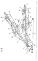
- Figure 3 shows a side view and Figure 4 is a plan view of the invention Packing device 3 in an attached position on the Bellen20 press 1, which only with the attachment 2, the wheels 7 and the flap opening 5th is shown.
- the packaging device 3 consists of two arranged in parallel Winder side walls 20, which the frame 21 of the packaging device 3 form, a changing table 22 and a support arm 23 for the rotatably mounted Wrapping arms 24.
- the winder side walls 20 represent the load-bearing elements of the packaging device 3 and are via a transverse roller 25 or their Axis of rotation connected to each other at a distance, with additional cross struts for Stability improvement can be provided.
- the winder side walls 20 extend in Longitudinal direction of the entire train unit and have a rear, slightly down extending leg 26 for mounting a parking support 27 and a upwardly projecting trapezoidal approach 28, which u. a. for fastening the front guide rails 29 and pivotable mounting of the rear Guide rails 30 is provided.
- a parking support 31 is connected to the winder side walls 20, which partly directly with the winder side walls 20 or via a corresponding molded console are welded.
- the parking supports 27, 31 each exist from a height-adjustable foot part 33, which can be operated via a crank 34 is.
- the parking supports 27, 31 are lowered by means of the crank 34 and thus enable the packaging device 3 to be parked after loosening the baler 1.
- the changing table 22 is horizontal and vertical movably arranged.
- the changing table 22 consists of two parallel to the winder side walls 20 arranged changing table side walls 35, which through the front and the rear axle 36 of the winding rollers 37 are kept spaced apart and if necessary can be reinforced by further cross struts.
- the winding rollers 37 are in Covered in the longitudinal direction with a plurality of changing table belts 38, on which the Round bales come to rest.
- the winding rollers 37 are each on one side equipped with a drive wheel in the form of a ring gear 49 which, for example a chain drive can be driven and during the winding process for a rotation of the round bale around the circumference ensures that this over the entire Tread and the end faces can be wrapped.
- the changing table 22 has furthermore at the rear end one flanged to the changing table side walls 35 Pin 40 on the attachment of the two laterally outside Setting cylinder 41 allows.
- the actuating cylinders 41 are each with their fixed part via a further pin 42 with the winder side walls 20 pivotable connected and thus enable movement when retracting or extending of the changing table 22 within the guide rails 29, 30.
- the front and rear guide rails 29, 30 are on the inside of the Winder side walls 20 attached and are each diametrically opposite and arranged parallel to the guide rails 29, 30 on the same winder side, the guide rails 29, 30 arranged obliquely rising to the rear are.
- the front guide plates 29 are stationary connected to the winder side walls 20 while the rear guide rails 30 via a swivel joint 48, as can be seen in FIG. 3, with the winder side walls 35 are connected so that regardless of the position of the changing table 22 the rear guide rails 30 can be lowered, for example to put down the round bale.
- the guide rails 29, 30 each consist of a U-shaped bracket 43, which is welded to a round tube 44 at its free leg ends are and the round tubes 44 are arranged at a precisely defined distance from each other are and virtually form a roller conveyor.
- the round tubes 44 are on the for wrapping bales towards the open end, while the opposite direction pointing end is closed and the rear section is a kink in the middle Area and a kink towards the end, on the one hand, a different To enable slope of the round tubes 44 and thus the changing table lift differently and on the other hand a stable end position of the changing table to reach
- the brackets 43 can run the entire length of the guide rails 29, 30 or, as shown in the exemplary embodiment, from a plurality of spaced brackets 43, each having a guide rail 29, 30 are assigned.
- a lifting roller 45 runs between the two round tubes 44, which is adapted with its radial surface to the radius of the round tube 44 and is attached to a lifting roller shaft 46 via a slide bearing.
- the lifting roller axles 46 are diametrically opposite and corresponding to the guide rails 29, 30 spaced on each side of the changing table 22 and facing outwards arranged and concealed with the changing table side walls 35.
- One guide rail each 29 or 30 is a lifting roller axis 46 or lifting roller 45 of the changing table 22 assigned so that the changing table 22 simultaneously horizontally and vertically is movably mounted between the winder side walls 20. The relocation is made by the laterally arranged and acted upon actuating cylinder 41. Characterized in that the two axes 36 of the winding rollers 37 over the changing table side walls 20 can be held at a fixed predetermined distance these are only moved in parallel and at the same time horizontally and vertically.
- the actuating cylinders 41 can furthermore be used for the entire packaging device 2 with respect to the baler 1 if between the articulation point of the fixed part of the actuating cylinder 41 and the winder side walls 20, a movable, horizontal joint 56 is arranged and the changing table 22 blocked in the guide rails 29, 30 by, for example, a sliding block is.
- the design of the movable joint 56 is, for example, FIG. 3 removable, in which the hinge 56 between the suspension 12 and the rear continued winder side walls 20 is arranged.
- the joint 56 consists of a bolt 57 and a vertical stop surface 58 of the suspension 12, on the the front upward rounded edge 59 of the winder side wall 20 abuts and is held by the bolt 57 lying in a bore.
- the support arm 23, which is arranged above the changing table 22 consists of two vertical supports 50 and two horizontal cross struts 51.
- the horizontal supports 50 are in their lower base via a console 52 with the Winder side wall 20 connected, for example screwed or concealed.
- the upper cross struts 51 are brought together centrally over the changing table 22 and have a bearing 53 in which the two winding arms 24 can be rotated horizontally stored and movable via a drive motor 54.
- the film rolls 55 are attached, which for wrapping the Round bales are provided.
- the winding process is such that the two Winding rollers 37 are driven via the sprockets 49 and thus the Rotate round bales, while simultaneously the two wrapping arms 24 with the Foil rolls 55 are guided around the round bale.
- the special kind of Suspension of the support arm 23, laterally on the winder side walls 21 leads in Furthermore, that the flap opening 5 of the baler 1 can move freely to ensure that the flap opening 5 of the baler 1 moves freely between the horizontal Supports 50 and vertical cross struts 51 is movable and thus the Round bales can be ejected without disabilities.
- a requirement is however, that the two winding arms 24 in their basic position approximately transverse to Direction of travel are set. The same applies when lifting the packaging device Second
- Figure 5 shows a schematic side view of the baler 1 with the open Flap opening 5 and the transport device for receiving the round bale 60 and the sequence of movements when ejecting.
- the round bale 60 falls after opening the flap opening 5 on the transport device, d. H. the changing table 22, which via the previously described actuating cylinder 41 in the lowest position below the flap opening 5 has been moved and remains in the recess 61 between the two winding rollers 37 and the changing table belts 38 are.
- FIG. 6 shows a schematic side view of the round baler 1 from FIG. 1 and the transport device with movement of the round bale 60 during transport to the packaging device, not shown.
- the transport device i.e. H. the changing table 22 together with the finished wrapped round bale 60 from the lower position near the opening flap 5 by a simultaneous vertical and move it horizontally into the upper position for further processing, wherein this end position is below the winding arms, not shown.
- Another round bale can be wrapped during transport 60 can be started.
- Figure 7 shows a schematic side view of the round baler 1 and Transport device with movement of the round bale 60 when dropping the transport device.
- the finished wrapped round bale 60 is lowered the rear guide rails 30 of the changing table 22, as already stated, caused to roll independently, the changing table belts 38 on the Roll 25 pressed between the two winder side walls 20 and simultaneously in the upper area can be stretched so that the round bale 60 better and lighter can roll off.
- Figure 8 shows a simplified side view of the transport in a raised position Position for driving on the road or in the field.
- Winder side wall 20 the front and rear guide rails 29, 30, the lifting rollers 45 and lifting roller axles 46 and the winding rollers 37 and the suspension of the Packing device 3 shown.
- a horizontally movable joint 56 is arranged on the winder side walls 20, soft allows lifting of the packaging device 3 on the one hand and on the other hand due to the off-center upward position and the vertical Stop surface 58 an almost rigid connection between the winder side walls 20 and the suspension 12 on the baler 1 by the weight of the Packaging device 3 allows. Possibly. can be locked by a bolt of the joint 56 are made.
- the packaging device is raised 3 through the lateral actuating cylinders 41 at an angle of approximately 30 degrees, if the changing table 22 in the guide rails 29, 30 by, for example, a Sliding block is blocked.
- the slot nut is here at the rear End of the guide rail 30 between the round tubes 44 with one on the lifting roller adapted curvature in front of the rear lifting rollers 45 and clamped by one Locking bolt held.
- Figure 9 shows a simplified side view of the packaging device 3 with the Receiving position and the winding position of the changing table 22 and in a lowered Position of the rear guide rails 30 for depositing the round bale 60.
- the one from the baler 1 Round bale 60 taken up is wrapped by the packaging device 3 and then by lowering the rear guide rails 30 of the changing table 22, as already explained, caused to roll off independently, whereby the changing table belts 38 on the roll 25 between the two winder side walls pressed and simultaneously tensioned in the upper area, so that the Round bales 60 can roll off more easily.
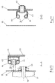
- FIG. 10 shows a partial section along the connecting line AA
- FIG. 11 shows a partial section along the connecting line B - B through the guide rails 29, 30, once with lifting roller 45 and lifting roller axis 46 and the drivable Sprocket 49 and one with swivel 48 between rear guide rail 30 and winder sidewall 20.
- FIG. 12 shows a simplified side view of the packaging device 3 according to FIG Figure 3 or 9 with an additional bale brake 62.
- the packaging device 3 is in different positions of the rear guide rails 30 and the changing table 22 with round bale 60 shown, the bale brake 62 in the wrapping position in the basic position and in the lowered position in addition to the floor is shown pivoted.
- the bale brake 62 consists of two lateral support arms 66, which is pivotable on the rear guide rails 30 via one each Console 67 attached and by a crossbar not recognizable from the side view are interconnected.
- the consoles 67 can, for example, on the rear guide rails 30 are welded and each have a pivot point 73 for the support arms 66.
- the bale brake 62 is actuated in the shown Exemplary embodiment by the actuating cylinder 47, which is used to lower the rear Guide rails 30 is used. Alternatively there is the possibility of an additional one Use actuating cylinders. So that the bale brake 62 only with success Lowering of the changing table 22 is solved, a deflection mechanism is required that of a first lever arm 68, a first push rod 64, a bell crank 63 and a second push rod 65.
- the movement of the bale brake 62 takes place indirectly through the actuating cylinder 47 rear guide rails 30, the actuating cylinder 47 for lowering the rear Guide rails 30 centrally at one end around an axis of rotation 70 pivotable lever arm 68 and at the other end on the rear guide rails 30 is attached and wherein the lever arm 68 for lifting the rear guide rails abuts against a stop 69 and at the free end of the lever arm a push rod 64 is fastened, which with a about an axis of rotation 71st pivotable angle lever 63 is connected, at the second end with the support arms 66 of the bale brake 62 connected push rod 65 is attached.
Landscapes
- Life Sciences & Earth Sciences (AREA)
- Environmental Sciences (AREA)
- Storage Of Harvested Produce (AREA)
- Basic Packing Technique (AREA)
Abstract
Description
- Fig.1
- eine Seitenansicht einer Ballenpresse mit Anbauvorrichtung für eine Verpackungsvorrichtung,
- Fig.2
- eine Draufsicht der Ballenpresse gemäß Figur 1,
- Fig.3
- eine Seitenansicht der erfindungsgemäßen Verpackungsvorrichtung mit Führungsschienen und Anhängevorrichtung,
- Fig.4
- eine Draufsicht auf die Verpackungsvorrichtung gemäß Figur 3,
- Fig.5
- eine schematische Seitenansicht der Ballenpresse mit geöffneter Haube und Transportvorrichtung zur Aufnahme des Rundballens sowie einem skizzierten Bewegungsablauf beim Auswurf,
- Fig.6
- eine schematische Seitenansicht der Rundballenpresse und Transportvorrichtung mit Bewegungsablauf des Rundballens beim Transport zur Verpackungsvorrichtung,
- Fig.7
- eine schematische Seitenansicht der Rundballenpresse und Verpackungsvorrichtung mit Bewegungsablauf des Rundballens beim Ablegen von dem Wickeltisch,
- Fig.8
- eine vereinfachte Seitenansicht der Verpackungsvorrichtung in einer angehobenen Position zum Fahren auf der Straße,
- Fig.9
- eine vereinfachte Seitenansicht der Verpackungsvorrichtung mit der Wickelposition und der abgesenkten Position der hinteren Führungsschienen,
- Fig.10
- einen, Teilschnitt gemäß der Verbindungslinie A - A durch die Führungsschienen, Hubrolle und Hubrollenachse,
- Fig.11
- einen weiteren Teilschnitt gemäß der Verbindungslinie B-B und
- Fig.12
- eine vereinfachte Seitenansicht der Verpackungsvorrichtung gemäß Figur 3 mit Ballenbremse.
- 1
- Ballenpresse
- 2
- Anbauvorrichtung
- 3
- Verpackungsvorrichtung
- 4
- Gehäuse
- 5
- Klappenöffnung
- 6
- Achse
- 7
- Rad
- 8
- Längsstrebe
- 9
- Zugdeichsel
- 10
- Konsole
- 11
- Zapfen
- 12
- Aufhängung
- 13
- Verriegelungsbolzen
- 14
- Strebe
- 15
- Stützrad
- 16
- Rundballen
- 17
- Verriegelungskeil
- 18
- Anschlag
- 19
- Konsole
- 20
- Wicklerseitenwand
- 21
- Rahmengestell
- 22
- Wickeltisch
- 23
- Tragarm
- 24
- Wickelarm
- 25
- Rolle
- 26
- Schenke
- 27
- Abstellstütze
- 28
- Ansatz
- 29
- Führungsschiene
- 30
- Führungsschiene
- 31
- Abstellstütze
- 33
- Fußteil
- 34
- Kurbel
- 35
- Wickeltischseitenwand
- 36
- Achse
- 37
- Wickelrolle
- 38
- Wickeltischband
- 40
- Zapfen
- 41
- Stellzylinder
- 42
- Zapfen
- 43
- Konsole
- 44
- Rundrohr
- 45
- Hubrolle
- 46
- Hubrollenachse
- 47
- Stellzylinder
- 48
- Drehgelenk
- 49
- Zahnkranz
- 50
- Stütze
- 51
- Querstrebe
- 52
- Konsole
- 53
- Lager
- 54
- Antriebsmotor
- 55
- Folienrolle
- 56
- Gelenk
- 57
- Bolzen
- 58
- Anschlagfläche
- 59
- Kante
- 60
- Rundballen
- 61
- Mulde
- 62
- Ballenbremse
- 63
- Winkelhebel
- 64
- Schubstange
- 65
- Schubstange
- 66
- Tragarm
- 67
- Konsole
- 68
- Hebelarm
- 69
- Anschlag
- 70
- Drehpunkt
- 71
- Drehpunkt
- 72
- Fuß
- 73
- Anlenkpunkt
Claims (24)
- Vorrichtung zum Pressen und Umwickeln von Rundballen aus Heu, Halbheu, Stroh oder ähnlichem Halmgut, bestehend aus einer Ballenpresse (1) und einer Verpackungsvorrichtung (3), welche beide über zumindest einem sich auf Laufrädern abstützenden Rahmengestell miteinander verbunden sind und einer in Längsrichtung bewegbaren Transportvorrichtung, welche einen fertig gewickelten Rundballen (60) von der Ballenauswurföffnung zur Verpackungsvorrichtung (3) transportiert,
dadurch gekennzeichnet, dass die Transportvorrichtung den fertigen Rundballen (60) nach Auswurf aus der Ballenpresse (1) durch eine zumindest in einem Teilbereich gleichzeitige vertikale und horizontale Bewegung nach hinten anhebend zur Verpackungsvorrichtung (3) bewegt und wobei die Verbindung zwischen dem Rahmengestell (8, 10) der Ballenpresse (1) und der Verpackungsvorrichtung (3) starr durch ein die Verpackungsvorrichtung (3) aufnehmendes Rahmengestell (21) oder durch zwei über mindestens ein Drehgelenk (56) miteinander verbundene Rahmengestelle (8, 10, 21) erfolgt, wobei das Drehgelenk (56) eine vertikale Schwenkbewegung vorsieht. - Vorrichtung nach Anspruch 1,
dadurch gekennzeichnet, dass das Rahmengestell (21) der Verpackungsvorrichtung (3) über eine verriegelbare starre Aufhängung (12) mit dem Rahmengestell der Ballenpresse (1) verbindbar ist. - Vorrichtung nach einem oder mehreren der Ansprüche 1 bis 2,
dadurch gekennzeichnet, dass die Achse (6) der Laufräder (7) gegenüber der Ballenpresse (1) entgegen der Hauptfahrtrichtung durch eine dem Schwerpunkt angepasste Verlagerung nach hinten und/oder unten versetzt angeordnet ist oder zusätzliche anhängbare Laufräder für die Verpackungsvorrichtung (3) vorgesehen sind. - Vorrichtung nach einem oder mehreren der Ansprüche 1 bis 3,
dadurch gekennzeichnet, dass die Verpackungsvorrichtung (3) ein Traggestell für einen Wickelarm (24) aufweist, welches aus zumindest zwei vertikalen Stützen (50) und mindestens zwei miteinander im Drehpunkt der Wickelarme (24) verbundene horizontale oder schräg verlaufende Stützen (51) besteht, wobei die vertikalen Stützen (51) seitlich neben der Ballenauswurfsöffnung der Ballenpresse (1) mit dem Rahmengestell (21) verbunden sind. - Vorrichtung nach einem oder mehreren der Ansprüchen 1 bis 4,
dadurch gekennzeichnet, dass das Traggestell V- oder U-förmig zur Ballenpresse (1) hin geöffnet ist und die seitlichen Stützen (50) derart beabstandet sind, dass die Klappenöffnung der Ballenpresse (1) zwischen den seitlichen Stützen (50) frei beweglich ist. - Vorrichtung nach einem oder mehreren der Ansprüche 1 bis 5,
dadurch gekennzeichnet, dass die Verpackungsvorrichtung (3) oder das Rahmengestell (21) mit zumindest einem drehbar gelagerten und mitlaufenden Rad ausgestattet ist. - Vorrichtung nach einem oder mehreren der Ansprüche 1 bis 6
dadurch gekennzeichnet, dass die Transportvorrichtung den fertigen Rundballen (60) nach Auswurf aus der Ballenpresse (1) durch eine zumindest in einem Teilbereich gleichzeitige vertikale und horizontale Bewegung nach hinten anhebend zur Verpackungsvorrichtung (3) bewegt und wobei die Transportvorrichtung von einem in Führungsschienen (29, 30) bewegbaren Wickeltisch (22) gebildet wird, und zumindest die hinteren Führungsschienen (30) des Wickeltisches (22) über ein Drehgelenk (48) verschwenkbar sind. - Vorrichtung nach einem oder mehreren der Ansprüche 1 bis 7,
dadurch gekennzeichnet, dass die Klappenöffnung (5) der Ballenpresse (1) unabhängig von der Position der Transportvorrichtung mit oder ohne Rundballen (60) zu öffnen oder zu schließen ist. - Vorrichtung nach einem oder mehreren der Ansprüche 1 bis 8,
dadurch gekennzeichnet, dass der Wickeltisch (22) aus einem Rahmenelement (35) besteht, in dem mindestens zwei antreibbare und quer zur Längsrichtung beabstandete Wickelrollen (37) drehbar gelagert sind, welche in Längsrichtung angeordnete Wickeltischbänder (38) aufweisen. - Vorrichtung nach Anspruch 9,
dadurch gekennzeichnet, dass das Rahmenelement (35) vier Hubrollenachsen (46) aufweist, welche diametral und paarweise gegenüberliegend angeordnet und über eine Hubrolle (45) in jeweils einer schräg verlaufenden und nach hinten ansteigenden Führungsschiene (29,30) verschiebbar gelagert sind. - Vorrichtung nach einem oder mehreren der Ansprüche 1 bis 10,
dadurch gekennzeichnet, dass die Führungsschienen (29,30) jeweils diametral gegenüberliegend und parallel verlaufend mit dem Rahmengestell (21) verbunden sind, wobei zumindest die hinteren Führungsschienen (30) über ein Drehgelenk (48) schwenkbar an dem Rahmengestell (21) befestigt sind. - Vorrichtung nach einem oder mehreren der Ansprüche 1 bis 11,
dadurch gekennzeichnet, dass die Hubrollenachsen (46) des Wickeltisches (22) mit Hubrollen (45) und Gleitlagern in den Führungsschienen (29,30) über zumindest einen Steilzylinder (41) verfahrbar gelagert sind. - Vorrichtung nach einem oder mehreren der Ansprüche 7 bis 12,
dadurch gekennzeichnet, dass die Führungsschienen (29,30) des Wickeltisches (22) schräg verlaufend und nach hinten ansteigend ausgebildet sind, wobei zumindest an einem Ende ein horizontal verlaufender Führungsansatz ausgebildet ist. - Vorrichtung nach einem oder mehreren der Ansprüche 7 bis 12,
dadurch gekennzeichnet, dass die Führungsschienen (29,30) des Wickeltisches (22) im mittleren Bereich abgewinkelt oder gebogen ausgebildet sind. - Vorrichtung nach einem oder mehreren der Ansprüche 7 bis 12,
dadurch gekennzeichnet, dass die Führungsschienen (29,30) des Wickeltisches (22) im vorderen, unteren Bereich zunächst flach ansteigend und anschließend stärker ansteigend ausgebildet sind. - Vorrichtung nach einem oder mehreren der Ansprüche 1 - 15,
dadurch gekennzeichnet; dass das Rahmengestell (21) mit den jeweils diametral gegenüberliegenden Führungsschienen (29,30) mittels eines weiteren oder der vorhandenen Stellzylinder (41) über ein Gelenk (62) anhebbar ausgebildet ist. - Vorrichtung nach Anspruch 11,
dadurch gekennzeichnet, dass die hinteren diametral gegenüberliegenden Führungsschienen (30) über einen weiteren Stellzylinder (47) nach Beendigung des Wickelvorganges nach hinten absenkbar ausgebildet sind. - Vorrichtung nach einem oder mehreren der Ansprüche 1 bis 17,
dadurch gekennzeichnet, dass nach Beendigung des Wickelvorganges und dem Absenken der hinteren Führungsschienen (30) eine fest mit dem Rahmengestell (21) verbundene Rolle (25) gegen die Wickeltischbänder (38) von unten drückt und die Wickeltischbänder im oberen Bereich spannt. - Vorrichtung nach einem oder mehreren der Ansprüche 1 bis 18,
dadurch gekennzeichnet, dass das Rahmengestell (21) bzw. die hinteren Führungsschienen (30) eine Ballenbremse (62) aufweisen, welche schwenkbar und quer zur Längsrichtung mit dem Rahmengestell (21) bzw. den Führungsschienen (30) über eine Konsole (67) verbunden ist. - Vorrichtung nach einem oder mehreren der Ansprüche 1 bis 19,
dadurch gekennzeichnet, dass die Ballenbremse (62) aus zwei seitlichen um einen Drehpunkt verschwenkbaren Tragarmen (66) besteht, welche über eine Querstange miteinander verbunden sind und den Rundballen (60) halten. - Vorrichtung nach Anspruch 20,
dadurch gekennzeichnet, dass die Ballenbremse (62) unmittelbar durch einen weiteren Stellzylinder oder über einen Umlenkhebel (63) und mindestens eine Schubstange (64, 65) absenkbar ist. - Vorrichtung nach Anspruch 21,
dadurch gekennzeichnet, dass der Stellzylinder (47) zum Absenken der hinteren Führungsschienen (30) einenends mittig an einem um eine Drehachse (70) verschwenkbaren Hebelarm (68) und anderenends an den hinteren Führungsschienen (30) befestigt ist, wobei der Hebelarm (68) zum Anheben der hinteren Führungsschienen (30) abstützend an einem Anschlag (69) anliegt und an dem freien Ende des Hebelarms (68) eine Schubstange (64) befestigt ist, die mit einem um eine Drehachse (71) verschwenkbaren Winkelhebel (72) verbunden ist, an dessen zweiten Ende eine mit den Tragarmen (66) verbundene Schubstange (65) befestigt ist. - Vorrichtung nach einem oder mehreren der Ansprüche 1 bis 22,
dadurch gekennzeichnet, dass das Rahmengestell (21) im hinteren Bereich einen beim Absenken der hinteren Führungsschienen (30) auf den Boden aufsetzenden Fuß (72) aufweist. - Vorrichtung nach einem oder mehreren der Ansprüche 1 bis 23,
dadurch gekennzeichnet, dass der Wickeltisch (22) mit einer elektronischen Neigungsregelung ausgestattet ist, welche den Wickeltisch (22) während des Wickelvorganges 15 unabhängig von der Arbeitslage der Verpackungsvorrichtung (3) in der Horizontalen hält.
Applications Claiming Priority (4)
| Application Number | Priority Date | Filing Date | Title |
|---|---|---|---|
| DE19731520A DE19731520C2 (de) | 1997-07-23 | 1997-07-23 | Vorrichtung zum Pressen und Umwickeln von Rundballen |
| DE19731520 | 1997-07-24 | ||
| EP98113453A EP0893053B1 (de) | 1997-07-23 | 1998-07-18 | Vorrichtung zum Pressen und Umwickeln von Rundballen |
| EP02003613A EP1210862B1 (de) | 1997-07-23 | 1998-07-18 | Vorrichtung zum Pressen und Umwickeln von Rundballen |
Related Parent Applications (3)
| Application Number | Title | Priority Date | Filing Date |
|---|---|---|---|
| EP02003613A Division EP1210862B1 (de) | 1997-07-23 | 1998-07-18 | Vorrichtung zum Pressen und Umwickeln von Rundballen |
| EP98113453.9 Division | 1998-07-18 | ||
| EP02003613.3 Division | 2002-02-16 |
Publications (3)
| Publication Number | Publication Date |
|---|---|
| EP1452086A1 true EP1452086A1 (de) | 2004-09-01 |
| EP1452086B1 EP1452086B1 (de) | 2006-12-13 |
| EP1452086B8 EP1452086B8 (de) | 2010-04-14 |
Family
ID=7836554
Family Applications (4)
| Application Number | Title | Priority Date | Filing Date |
|---|---|---|---|
| EP98113453A Expired - Lifetime EP0893053B1 (de) | 1997-07-23 | 1998-07-18 | Vorrichtung zum Pressen und Umwickeln von Rundballen |
| EP04006040A Expired - Lifetime EP1452086B8 (de) | 1997-07-23 | 1998-07-18 | Vorrichtung zum Pressen und Umwickeln von Rundballen |
| EP02003613A Expired - Lifetime EP1210862B1 (de) | 1997-07-23 | 1998-07-18 | Vorrichtung zum Pressen und Umwickeln von Rundballen |
| EP02003612A Expired - Lifetime EP1210861B1 (de) | 1997-07-23 | 1998-07-18 | Vorrichtung zum Pressen und Umwickeln von Rundballen |
Family Applications Before (1)
| Application Number | Title | Priority Date | Filing Date |
|---|---|---|---|
| EP98113453A Expired - Lifetime EP0893053B1 (de) | 1997-07-23 | 1998-07-18 | Vorrichtung zum Pressen und Umwickeln von Rundballen |
Family Applications After (2)
| Application Number | Title | Priority Date | Filing Date |
|---|---|---|---|
| EP02003613A Expired - Lifetime EP1210862B1 (de) | 1997-07-23 | 1998-07-18 | Vorrichtung zum Pressen und Umwickeln von Rundballen |
| EP02003612A Expired - Lifetime EP1210861B1 (de) | 1997-07-23 | 1998-07-18 | Vorrichtung zum Pressen und Umwickeln von Rundballen |
Country Status (4)
| Country | Link |
|---|---|
| EP (4) | EP0893053B1 (de) |
| AT (4) | ATE347794T1 (de) |
| DE (5) | DE19731520C2 (de) |
| DK (1) | DK1210862T3 (de) |
Families Citing this family (25)
| Publication number | Priority date | Publication date | Assignee | Title |
|---|---|---|---|---|
| DE19806460C1 (de) * | 1998-02-17 | 1999-08-12 | Welger Geb | Fahrbare Ballenpresse für Stroh, Heu oder ähnliches Halmgut |
| DE19919323A1 (de) * | 1999-04-28 | 2000-11-02 | Deere & Co | Ballenwickelgerät |
| DE19919322A1 (de) * | 1999-04-28 | 2000-11-09 | Deere & Co | Ballenwickelgerät |
| EP1077024A1 (de) * | 1999-08-19 | 2001-02-21 | Kverneland Gottmadingen GmbH & Co. KG | Landwirtschaftliche Funktionseinheit |
| DE20015653U1 (de) | 2000-09-08 | 2001-04-19 | Schuster, Thomas, 87754 Kammlach | Wickelvorrichtung |
| EP1266562A1 (de) | 2001-06-11 | 2002-12-18 | Lely Enterprises AG | Rundballenpresse für landwirtschaftliche Halmgüter |
| EP1266563B1 (de) | 2001-06-11 | 2008-01-23 | Welger Maschinenfabrik GmbH | Rundballenpresse für landwirtschaftliche Halmgüter |
| EP1386532B1 (de) * | 2002-08-03 | 2006-11-15 | Welger Maschinenfabrik GmbH | Vorrichtung zum Umhüllen von Körpern |
| EP1393614A3 (de) | 2002-08-28 | 2009-06-03 | Deere & Company | Wickelgerät |
| DE10240091A1 (de) * | 2002-08-28 | 2004-03-11 | Deere & Company, Moline | Wickelgerät |
| DE10257252A1 (de) * | 2002-12-07 | 2004-08-12 | Deere & Company, Moline | Presse, insbesondere Rundballenpresse |
| DE10334681B3 (de) * | 2003-07-30 | 2005-05-04 | Maschinenfabrik Bernard Krone Gmbh | Vorrichtung zum Umhüllen oder Verpacken von insbesondere landwirtschaftlichen Erntegutballen |
| DE50306530D1 (de) | 2003-12-12 | 2007-03-29 | Lely Entpr Ag | Umwickeln mit nur einem Folienende |
| EP2090153B1 (de) | 2008-02-13 | 2015-09-09 | Usines CLAAS France S.A.S. | Rundballenpresse |
| IES20080942A2 (en) * | 2008-11-26 | 2009-12-09 | Idough Invest Company | A bale-wrapping machine |
| FI123731B (fi) * | 2012-04-05 | 2013-10-15 | Agronic Oy | Paalain ja menetelmä paalin muodostamiseksi |
| GB201410117D0 (en) * | 2014-06-06 | 2014-07-23 | Idough Invest Company | Improvements in and relating to bale wrapping machines |
| CN105460257B (zh) * | 2015-12-23 | 2018-05-08 | 甘肃省机械科学研究院 | 一种悬挂式青贮圆捆裹膜机 |
| NL2016179B1 (en) * | 2016-01-28 | 2017-08-10 | Forage Innovations Bv | Wrapping apparatus and method for softly depositing the wrapped object on the ground. |
| FI128611B (fi) * | 2018-12-14 | 2020-08-31 | Agronic Oy | Paalinkäärijä ja yhdistelmäkone |
| CN111528501B (zh) * | 2020-05-26 | 2024-09-06 | 磻溪(南京)科技有限公司 | 一种秸秆捡拾打捆机 |
| PL242168B1 (pl) * | 2020-09-01 | 2023-01-23 | Metal Fach Spolka Z Ograniczona Odpowiedzialnoscia | Prasoowijarka |
| DE102022115782A1 (de) * | 2022-06-24 | 2024-01-04 | Maschinenfabrik Bernard Krone GmbH & Co. KG | Ballenpresse für landwirtschaftliches Erntegut |
| CN116750252B (zh) * | 2023-08-16 | 2023-10-31 | 合肥优尔电子科技有限公司 | 一种用于电线电缆的缠绕包装设备 |
| DE102024125510A1 (de) * | 2024-09-05 | 2026-03-05 | Maschinenfabrik Bernard Krone GmbH & Co. KG | Verfahren zum betreiben einer rundballenpresse |
Citations (3)
| Publication number | Priority date | Publication date | Assignee | Title |
|---|---|---|---|---|
| DE4120733A1 (de) * | 1991-06-22 | 1993-01-07 | Deere & Co | Maschine zum verpacken eines ballens mit folie |
| DE4208091A1 (de) * | 1992-03-13 | 1993-10-07 | Helmut Schenke | Vorrichtung zum Pressen und Einwickeln von Ballen |
| EP0865723A1 (de) * | 1997-03-17 | 1998-09-23 | Herbert Göweil | Ballenbilder für landwirtschaftliches Halmgut |
Family Cites Families (4)
| Publication number | Priority date | Publication date | Assignee | Title |
|---|---|---|---|---|
| AT397957B (de) | 1989-04-03 | 1994-08-25 | Lisec Peter | Vorrichtung zum füllen der randfuge von isolierglasscheiben mit versiegelungsmasse |
| FR2645399B1 (fr) * | 1989-04-06 | 1992-02-14 | Dario Sa | Dispositif de chargement et de dechargement de balles cylindriques de paille ou de fourrage |
| GB8912832D0 (en) * | 1989-06-03 | 1989-07-19 | Underhaug As | Bale-wrapper apparatus |
| DE4138499A1 (de) * | 1991-11-22 | 1993-05-27 | Busatis Werke Kg | Rundballenwickelgeraet |
-
1997
- 1997-07-23 DE DE19731520A patent/DE19731520C2/de not_active Expired - Fee Related
-
1998
- 1998-07-18 EP EP98113453A patent/EP0893053B1/de not_active Expired - Lifetime
- 1998-07-18 DK DK02003613T patent/DK1210862T3/da active
- 1998-07-18 EP EP04006040A patent/EP1452086B8/de not_active Expired - Lifetime
- 1998-07-18 DE DE59812839T patent/DE59812839D1/de not_active Expired - Lifetime
- 1998-07-18 AT AT04006040T patent/ATE347794T1/de not_active IP Right Cessation
- 1998-07-18 AT AT98113453T patent/ATE233993T1/de active
- 1998-07-18 DE DE59813846T patent/DE59813846D1/de not_active Expired - Lifetime
- 1998-07-18 EP EP02003613A patent/EP1210862B1/de not_active Expired - Lifetime
- 1998-07-18 DE DE59807438T patent/DE59807438D1/de not_active Expired - Lifetime
- 1998-07-18 AT AT02003613T patent/ATE296533T1/de not_active IP Right Cessation
- 1998-07-18 EP EP02003612A patent/EP1210861B1/de not_active Expired - Lifetime
- 1998-07-18 AT AT02003612T patent/ATE287636T1/de active
- 1998-07-18 DE DE59812522T patent/DE59812522D1/de not_active Expired - Lifetime
Patent Citations (3)
| Publication number | Priority date | Publication date | Assignee | Title |
|---|---|---|---|---|
| DE4120733A1 (de) * | 1991-06-22 | 1993-01-07 | Deere & Co | Maschine zum verpacken eines ballens mit folie |
| DE4208091A1 (de) * | 1992-03-13 | 1993-10-07 | Helmut Schenke | Vorrichtung zum Pressen und Einwickeln von Ballen |
| EP0865723A1 (de) * | 1997-03-17 | 1998-09-23 | Herbert Göweil | Ballenbilder für landwirtschaftliches Halmgut |
Also Published As
| Publication number | Publication date |
|---|---|
| ATE347794T1 (de) | 2007-01-15 |
| EP1210861B1 (de) | 2005-01-26 |
| EP1210861A2 (de) | 2002-06-05 |
| EP1210861A3 (de) | 2002-08-21 |
| DE19731520C2 (de) | 1999-08-05 |
| DE59813846D1 (de) | 2007-01-25 |
| ATE296533T1 (de) | 2005-06-15 |
| DK1210862T3 (da) | 2005-10-03 |
| ATE233993T1 (de) | 2003-03-15 |
| EP1452086B8 (de) | 2010-04-14 |
| EP1210862B1 (de) | 2005-06-01 |
| DE59812522D1 (de) | 2005-03-03 |
| EP1452086B1 (de) | 2006-12-13 |
| DE59807438D1 (de) | 2003-04-17 |
| EP1210862A2 (de) | 2002-06-05 |
| EP0893053A1 (de) | 1999-01-27 |
| DE19731520A1 (de) | 1999-02-04 |
| ATE287636T1 (de) | 2005-02-15 |
| DE59812839D1 (de) | 2005-07-07 |
| EP0893053B1 (de) | 2003-03-12 |
| EP1210862A3 (de) | 2002-08-21 |
Similar Documents
| Publication | Publication Date | Title |
|---|---|---|
| EP0893053B1 (de) | Vorrichtung zum Pressen und Umwickeln von Rundballen | |
| EP0269685B1 (de) | Schlepper zum bugsieren eines flugzeuges ohne schleppstange | |
| EP0543145B1 (de) | Rundballenwickelgerät | |
| EP1438889B1 (de) | Presse, insbesondere Rundballenpresse | |
| DE3511188A1 (de) | Ballenhandhabungsvorrichtung | |
| DE4120733C2 (de) | Fahrbare Ballenpresse | |
| EP0983720A1 (de) | Vorrichtung zum Umwickeln einer Rundballe | |
| DE2530249C3 (de) | Wickelballenpresse | |
| DE3501062C2 (de) | ||
| DE10240091A1 (de) | Wickelgerät | |
| DE7608114U1 (de) | Transportgeraet, bestehend aus einem behaelter und einem transportfahrzeug | |
| EP1048201A1 (de) | Ballenwickelgerät | |
| EP3440922B1 (de) | Ballentransportwagen | |
| DE69002552T2 (de) | Ballenwickler mit kippbarem Drehtisch. | |
| DE3304166C2 (de) | Rundballenübernahme- und Transportfahrzeug | |
| DE102004022874A1 (de) | Ladewagen | |
| DE2821991A1 (de) | Lade- und transportgeraet fuer lasteinheiten sowie verfahren zum betrieb desselben | |
| EP1736304A2 (de) | Auf die Ladefläche eines LKW aufladbare Vorrichtung zur Verdichtung von Abfällen in einem Container | |
| EP0767112A1 (de) | Silobeschickungsvorrichtung | |
| DE2115861A1 (de) | Ballenladewagen | |
| WO2016118986A1 (de) | Vorrichtung zum laden und zum transport von rundballen | |
| DE2553437A1 (de) | Vorrichtung zur handhabung von heu- oder futterballen | |
| DE2553438A1 (de) | Vorrichtung zur handhabung von heu- oder futterballen | |
| AT402774B (de) | Ladewagen für halmgutballen | |
| DE2029015B2 (de) | Kartoffellegemaschine mit kippkasten |
Legal Events
| Date | Code | Title | Description |
|---|---|---|---|
| PUAI | Public reference made under article 153(3) epc to a published international application that has entered the european phase |
Free format text: ORIGINAL CODE: 0009012 |
|
| AC | Divisional application: reference to earlier application |
Ref document number: 1210862 Country of ref document: EP Kind code of ref document: P Ref document number: 0893053 Country of ref document: EP Kind code of ref document: P |
|
| AK | Designated contracting states |
Kind code of ref document: A1 Designated state(s): AT BE CH CY DE DK ES FI FR GB GR IE IT LI LU MC NL PT SE |
|
| 17P | Request for examination filed |
Effective date: 20050301 |
|
| AKX | Designation fees paid |
Designated state(s): AT BE CH CY DE DK ES FI FR GB GR IE IT LI LU MC NL PT SE |
|
| 17Q | First examination report despatched |
Effective date: 20050422 |
|
| GRAP | Despatch of communication of intention to grant a patent |
Free format text: ORIGINAL CODE: EPIDOSNIGR1 |
|
| GRAS | Grant fee paid |
Free format text: ORIGINAL CODE: EPIDOSNIGR3 |
|
| GRAA | (expected) grant |
Free format text: ORIGINAL CODE: 0009210 |
|
| AC | Divisional application: reference to earlier application |
Ref document number: 1210862 Country of ref document: EP Kind code of ref document: P Ref document number: 0893053 Country of ref document: EP Kind code of ref document: P |
|
| AK | Designated contracting states |
Kind code of ref document: B1 Designated state(s): AT BE CH CY DE DK ES FI FR GB GR IE IT LI LU MC NL PT SE |
|
| PG25 | Lapsed in a contracting state [announced via postgrant information from national office to epo] |
Ref country code: IT Free format text: LAPSE BECAUSE OF FAILURE TO SUBMIT A TRANSLATION OF THE DESCRIPTION OR TO PAY THE FEE WITHIN THE PRESCRIBED TIME-LIMIT;WARNING: LAPSES OF ITALIAN PATENTS WITH EFFECTIVE DATE BEFORE 2007 MAY HAVE OCCURRED AT ANY TIME BEFORE 2007. THE CORRECT EFFECTIVE DATE MAY BE DIFFERENT FROM THE ONE RECORDED. Effective date: 20061213 Ref country code: DK Free format text: LAPSE BECAUSE OF FAILURE TO SUBMIT A TRANSLATION OF THE DESCRIPTION OR TO PAY THE FEE WITHIN THE PRESCRIBED TIME-LIMIT Effective date: 20061213 Ref country code: IE Free format text: LAPSE BECAUSE OF FAILURE TO SUBMIT A TRANSLATION OF THE DESCRIPTION OR TO PAY THE FEE WITHIN THE PRESCRIBED TIME-LIMIT Effective date: 20061213 Ref country code: NL Free format text: LAPSE BECAUSE OF FAILURE TO SUBMIT A TRANSLATION OF THE DESCRIPTION OR TO PAY THE FEE WITHIN THE PRESCRIBED TIME-LIMIT Effective date: 20061213 |
|
| REG | Reference to a national code |
Ref country code: GB Ref legal event code: FG4D Free format text: NOT ENGLISH |
|
| REG | Reference to a national code |
Ref country code: CH Ref legal event code: EP |
|
| REG | Reference to a national code |
Ref country code: IE Ref legal event code: FG4D Free format text: LANGUAGE OF EP DOCUMENT: GERMAN |
|
| REF | Corresponds to: |
Ref document number: 59813846 Country of ref document: DE Date of ref document: 20070125 Kind code of ref document: P |
|
| PG25 | Lapsed in a contracting state [announced via postgrant information from national office to epo] |
Ref country code: SE Free format text: LAPSE BECAUSE OF FAILURE TO SUBMIT A TRANSLATION OF THE DESCRIPTION OR TO PAY THE FEE WITHIN THE PRESCRIBED TIME-LIMIT Effective date: 20070313 |
|
| PG25 | Lapsed in a contracting state [announced via postgrant information from national office to epo] |
Ref country code: ES Free format text: LAPSE BECAUSE OF FAILURE TO SUBMIT A TRANSLATION OF THE DESCRIPTION OR TO PAY THE FEE WITHIN THE PRESCRIBED TIME-LIMIT Effective date: 20070324 |
|
| PG25 | Lapsed in a contracting state [announced via postgrant information from national office to epo] |
Ref country code: PT Free format text: LAPSE BECAUSE OF FAILURE TO SUBMIT A TRANSLATION OF THE DESCRIPTION OR TO PAY THE FEE WITHIN THE PRESCRIBED TIME-LIMIT Effective date: 20070514 |
|
| NLV1 | Nl: lapsed or annulled due to failure to fulfill the requirements of art. 29p and 29m of the patents act | ||
| GBV | Gb: ep patent (uk) treated as always having been void in accordance with gb section 77(7)/1977 [no translation filed] |
Effective date: 20061213 |
|
| ET | Fr: translation filed | ||
| PLBE | No opposition filed within time limit |
Free format text: ORIGINAL CODE: 0009261 |
|
| 26N | No opposition filed |
Effective date: 20070914 |
|
| PG25 | Lapsed in a contracting state [announced via postgrant information from national office to epo] |
Ref country code: GB Free format text: LAPSE BECAUSE OF FAILURE TO SUBMIT A TRANSLATION OF THE DESCRIPTION OR TO PAY THE FEE WITHIN THE PRESCRIBED TIME-LIMIT Effective date: 20061213 |
|
| REG | Reference to a national code |
Ref country code: CH Ref legal event code: PL |
|
| PG25 | Lapsed in a contracting state [announced via postgrant information from national office to epo] |
Ref country code: GR Free format text: LAPSE BECAUSE OF FAILURE TO SUBMIT A TRANSLATION OF THE DESCRIPTION OR TO PAY THE FEE WITHIN THE PRESCRIBED TIME-LIMIT Effective date: 20070314 Ref country code: LI Free format text: LAPSE BECAUSE OF NON-PAYMENT OF DUE FEES Effective date: 20070731 Ref country code: CH Free format text: LAPSE BECAUSE OF NON-PAYMENT OF DUE FEES Effective date: 20070731 |
|
| PG25 | Lapsed in a contracting state [announced via postgrant information from national office to epo] |
Ref country code: AT Free format text: LAPSE BECAUSE OF NON-PAYMENT OF DUE FEES Effective date: 20070718 |
|
| PG25 | Lapsed in a contracting state [announced via postgrant information from national office to epo] |
Ref country code: LU Free format text: LAPSE BECAUSE OF NON-PAYMENT OF DUE FEES Effective date: 20070718 Ref country code: FI Free format text: LAPSE BECAUSE OF FAILURE TO SUBMIT A TRANSLATION OF THE DESCRIPTION OR TO PAY THE FEE WITHIN THE PRESCRIBED TIME-LIMIT Effective date: 20061213 Ref country code: CY Free format text: LAPSE BECAUSE OF FAILURE TO SUBMIT A TRANSLATION OF THE DESCRIPTION OR TO PAY THE FEE WITHIN THE PRESCRIBED TIME-LIMIT Effective date: 20061213 |
|
| PLAA | Information modified related to event that no opposition was filed |
Free format text: ORIGINAL CODE: 0009299DELT |
|
| PLBE | No opposition filed within time limit |
Free format text: ORIGINAL CODE: 0009261 |
|
| STAA | Information on the status of an ep patent application or granted ep patent |
Free format text: STATUS: NO OPPOSITION FILED WITHIN TIME LIMIT |
|
| D26N | No opposition filed (deleted) | ||
| RBV | Designated contracting states (corrected) |
Designated state(s): AT BE CH DE DK FR GB IE LI NL |
|
| 26N | No opposition filed |
Effective date: 20070914 |
|
| RBV | Designated contracting states (corrected) |
Designated state(s): AT BE CH DE DK FR GB IE LI NL |
|
| PGFP | Annual fee paid to national office [announced via postgrant information from national office to epo] |
Ref country code: IT Payment date: 20090725 Year of fee payment: 12 |
|
| REG | Reference to a national code |
Ref country code: DE Ref legal event code: R084 Ref document number: 59813846 Country of ref document: DE |
|
| REG | Reference to a national code |
Ref country code: FR Ref legal event code: PLFP Year of fee payment: 18 |
|
| REG | Reference to a national code |
Ref country code: DE Ref legal event code: R084 Ref document number: 59813846 Country of ref document: DE Effective date: 20150520 |
|
| PGFP | Annual fee paid to national office [announced via postgrant information from national office to epo] |
Ref country code: FR Payment date: 20150626 Year of fee payment: 18 |
|
| PGFP | Annual fee paid to national office [announced via postgrant information from national office to epo] |
Ref country code: DE Payment date: 20150528 Year of fee payment: 18 |
|
| PGFP | Annual fee paid to national office [announced via postgrant information from national office to epo] |
Ref country code: BE Payment date: 20150721 Year of fee payment: 18 |
|
| PG25 | Lapsed in a contracting state [announced via postgrant information from national office to epo] |
Ref country code: BE Free format text: LAPSE BECAUSE OF NON-PAYMENT OF DUE FEES Effective date: 20160731 |
|
| REG | Reference to a national code |
Ref country code: DE Ref legal event code: R119 Ref document number: 59813846 Country of ref document: DE |
|
| PG25 | Lapsed in a contracting state [announced via postgrant information from national office to epo] |
Ref country code: FR Free format text: LAPSE BECAUSE OF NON-PAYMENT OF DUE FEES Effective date: 20160801 Ref country code: DE Free format text: LAPSE BECAUSE OF NON-PAYMENT OF DUE FEES Effective date: 20170201 |
|
| REG | Reference to a national code |
Ref country code: FR Ref legal event code: ST Effective date: 20170331 |