EP1451940B1 - Vorrichtung und verfahren zur erzeugung einer kodemaske - Google Patents
Vorrichtung und verfahren zur erzeugung einer kodemaske Download PDFInfo
- Publication number
- EP1451940B1 EP1451940B1 EP02755227A EP02755227A EP1451940B1 EP 1451940 B1 EP1451940 B1 EP 1451940B1 EP 02755227 A EP02755227 A EP 02755227A EP 02755227 A EP02755227 A EP 02755227A EP 1451940 B1 EP1451940 B1 EP 1451940B1
- Authority
- EP
- European Patent Office
- Prior art keywords
- mask
- output mask
- new output
- summation
- set bits
- Prior art date
- Legal status (The legal status is an assumption and is not a legal conclusion. Google has not performed a legal analysis and makes no representation as to the accuracy of the status listed.)
- Expired - Lifetime
Links
- 238000000034 method Methods 0.000 title claims description 19
- 230000000694 effects Effects 0.000 claims description 3
- 238000010586 diagram Methods 0.000 description 2
- 238000009825 accumulation Methods 0.000 description 1
- 238000010276 construction Methods 0.000 description 1
- PCHJSUWPFVWCPO-UHFFFAOYSA-N gold Chemical group [Au] PCHJSUWPFVWCPO-UHFFFAOYSA-N 0.000 description 1
- 230000003362 replicative effect Effects 0.000 description 1
Images



Classifications
-
- H—ELECTRICITY
- H04—ELECTRIC COMMUNICATION TECHNIQUE
- H04J—MULTIPLEX COMMUNICATION
- H04J13/00—Code division multiplex systems
- H04J13/10—Code generation
-
- H—ELECTRICITY
- H04—ELECTRIC COMMUNICATION TECHNIQUE
- H04J—MULTIPLEX COMMUNICATION
- H04J13/00—Code division multiplex systems
- H04J13/0007—Code type
- H04J13/0022—PN, e.g. Kronecker
- H04J13/0025—M-sequences
-
- H—ELECTRICITY
- H04—ELECTRIC COMMUNICATION TECHNIQUE
- H04L—TRANSMISSION OF DIGITAL INFORMATION, e.g. TELEGRAPHIC COMMUNICATION
- H04L9/00—Cryptographic mechanisms or cryptographic arrangements for secret or secure communications; Network security protocols
- H04L9/06—Cryptographic mechanisms or cryptographic arrangements for secret or secure communications; Network security protocols the encryption apparatus using shift registers or memories for block-wise or stream coding, e.g. DES systems or RC4; Hash functions; Pseudorandom sequence generators
- H04L9/065—Encryption by serially and continuously modifying data stream elements, e.g. stream cipher systems, RC4, SEAL or A5/3
- H04L9/0656—Pseudorandom key sequence combined element-for-element with data sequence, e.g. one-time-pad [OTP] or Vernam's cipher
- H04L9/0662—Pseudorandom key sequence combined element-for-element with data sequence, e.g. one-time-pad [OTP] or Vernam's cipher with particular pseudorandom sequence generator
-
- H—ELECTRICITY
- H04—ELECTRIC COMMUNICATION TECHNIQUE
- H04L—TRANSMISSION OF DIGITAL INFORMATION, e.g. TELEGRAPHIC COMMUNICATION
- H04L2209/00—Additional information or applications relating to cryptographic mechanisms or cryptographic arrangements for secret or secure communication H04L9/00
- H04L2209/04—Masking or blinding
- H04L2209/046—Masking or blinding of operations, operands or results of the operations
Definitions
- the invention relates to methods of, and apparatus for, code generation.
- the invention relates to methods of, and apparatus for, generating output masks for code generators.
- pn pseudonoise sequences that are also m-sequences (maximal length sequences) are commonplace, for example in the construction of Gold sequences used to scramble and descramble signals.
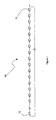
- Figure 1 illustrates a m-sequence generator 10 using the primitive (over Golay Field order 2) polynominal 1+x 7 +x 18 .
- the generator 10 comprises an 18 element shift register.
- the input to the first element 12 of the shift register is provided by performing an exclusive-or operation on the outputs of the 0th and 7th elements of the register.
- the m-sequence can be read from the shift register by combining in an exclusive-OR (XOR) operation the outputs of a combination of the shift register elements.
- the elements selected for the combination can be any predefined combinations of elements.
- the output of the shift register is simply the output of its 0th element. (The combination of elements forming the output will be called the output mask). Any certain combinations of elements can be used in the XOR operation, each combination corresponding to reading the m-sequence from a different point in its cycle. However, it can be difficult to determine which combinations produce the desired shifts.
- EP 0994573, US 5532695 and US 5228054 describe systems in which masks are applied to pn generator states. US 5532695 also describes a process for modifying such a mask using matrices.
- the invention provides a method of creating a new output mask for a m-sequence generator, comprising creating an intermediate mask for each bit set in an existing output mask and performing modulo-2 summation on all the intermediate masks produced to create the new output mask, wherein each intermediate mask is created by shifting a shift template by an offset equal to the offset of the corresponding set bit in the existing output mask.
- the invention also consists in apparatus for creating a new output mask for a m-sequence generator comprising generating means for generating an intermediate mask for each bit set in an existing output mask and combining means for performing modulo-2 summation on all the intermediate masks produced to create the new output mask, wherein the generating means produces each intermediate mask by shifting a shift template by an offset equal to the offset of the corresponding set bit in the existing output mask.
- each intermediate mask comprises an aligned portion aligned with the new output mask and the new output mask is produced through modulo-2 summation of all the aligned portions. If an intermediate mask has beyond its aligned portion an excess portion containing one or more set bits, then preferably said one or more excess portion set bits are used to influence the effect of the intermediate mask on the new output mask.
- the one or more excess portion said bits can be used to adjust the new output mask after or at the same time as their intermediate mask takes part in said summation.
- the one or more excess portion set bits may be used to adjust their intermediate mask before it takes part in said summation.
- the influence of one or more excess portion set bits is determined by the nature of a feedback arrangement in the generator.
- the invention has been expressed above in terms of a method for creating a new output mask for a m-sequence generator. It should be noted that the invention also extends to computer programmes (however embodied) for performing such methods.
- a m-sequence generator can be described using two mask words, each having a number of bits equal to the number of elements in the shift register upon which the m-sequence generator is based. Indeed, each element in the shift register has a respective bit in each of the mask words. In accordance with the prevalent bit significance convention, the rightmost bit in each mask is the 0th or least significant bit (lsb) of the mask word and the leftmost bit in each mask word is the most significant bit (msb).
- the two mask words are the output mask O and the feedback mask F.
- the output mask has bits set at only those positions corresponding to shift elements whose outputs are combined through an XOR operation to produce the output of the generator.
- the feedback mask has bits set at only those positions corresponding to shift elements whose outputs are combined through an XOR operation to produce the input to the first element of the shift register.
- the shift elements contributing to the output signal of a m-sequence generator can be varied in order to time shift the output m-sequence. If the output mask is O current and a time shift is applied, then the output mask becomes O new to specify the elements that contribute to the time shifted m-sequence. It will be apparent that where the shift register contains n elements 2 n -1 possible time shifts can be applied, i.e. given any arbitrary O current there are 2"-1 possible O new , each corresponding to a different time shift.
- O end When O current has just its lsb set (i.e. the m-sequence is simply taken from the output of the final shift element) it shall be known as O end .
- This embodiment uses the series of 2 n -1 possible updated output masks that can arise from time shifting O end as a set of shift templates in the calculation of an updated output mask O new corresponding to the application of some arbitrary forward time shift to some arbitrary current output mask O current .
- a shift template S c is selected which corresponds to the updated output mask for the application of a c cycle forward shift applied to O end .
- the selected shift template is S 6 , which is the result of performing a 6 cycle forward shift on O end .
- S 6 the selected shift template
- the applicable shift template S c is applied to O current to generate one or more intermediate masks. For each bit that is set in O current an intermediate mask I p is generated, where p denotes the offset of the bit from the least significant end of O current .
- I p denotes the offset of the bit from the least significant end of O current .
- a wrap-back mask W pq is generated, where q denotes the offset of the bit from the least significant end of E p .
- W pq is produced by offsetting F by q bits from its least significant end.
- E p is discarded leaving I p with just its n lsbs.
- the wrap-back mask(s) are summed using modulo-2 addition with the truncated I p to produce an updated I p .
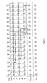
- a forward time shift of 18 cycles is applied to O current of 000000000011000001.
- S 18 is 000000000010000001.
- None of the intermediate masks contain any set bits beyond its 18 lsbs and therefore no wrap-back masks are required.
- the intermediate masks are simply combined by modulo-2 addition (equivalent to a bitwise XOR operation) to produce O new . This can be seen by performing a XOR operation on each column of the three rows I 0 , I 6 , I 7 in Figure 2.
- a forward time shift of 18 cycles is applied to an O current of 000000100011000001.
- I 0 , I 6 and I 7 are calculated as in the Figure 2 example.
- the generation of I 11 involves a wrap-back mask.
- W 11,0 is 000000000010000001.
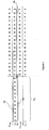
- a forward time shift of 12 cycles is applied to an O current 100000000000000000.
- S 12 is 000001000000000000 and this is offset by 17 bits to the left (as shown by bold arrow 20) as the first step in generating I 17 .
- I 17 is a 30 bit word with only its msb set.
- the m-sequence generator 26 can be seen.
- a network 28 of AND and XOR gates operates on the outputs of the elements of the shift register in generator 26 in order to produce the output m-sequence at node 29.
- the AND gates of the network 28 act as selectors to determine whether or not the outputs of the shift elements of the generator 26 participate in the XOR operation to produce the output 29.
- the AND gates of the network 29 are controlled by a row of registers 30 across which O current is stored. For example, when O current is O end , only the rightmost AND gate in network 28 can output a "logic-high" bit and thus only the output of the final shift element of the register 26 is used to produce the output 29.
- O current is loaded in parallel into the elements of shift register 32.
- Register 32 is then clocked to produce signal A which produces O new , as will now be described with reference to Figure 5b.
- S c is initially stored in shift register 34 and as the system clock advances, S c is shifted along shift register 40.
- the updated output mask O new is accumulated in the set of storage elements 36, each of which is arranged in a modulo-2 accumulation loop.
- the elements 36 accumulate bits passed to them from register 34 and from (via wrap-back network 38) register 40.
- the wrap-back network is a configuration of XOR gates which allows the circuit to produce the correct O new result when the I p have excess words E p containing set bits. All of the AND gates are controlled by the signal A, which is the train of O current values stored in register 32. Thus only when A is set to "logic-high" will the storage elements 36 be updated.
- the elements 36 When O current has been clocked out of the register 32, the elements 36 contain O new which can then be loaded into the registers 30 to update the output mask of the generator 26.
- a shift by an arbitrary amount, c can be decomposed into the relevant combination of the members of the set defined by S z .
- the use of the set of templates S z provides that the time taken to calculate O new for an arbitrary shift c using an n element shift register then becomes n ⁇ log 2 c ⁇ clock cycles.
- the logic circuit of Figure 5 can be made to calculate O new in a single clock cycle.
- the circuit could be arranged to calculate all the final intermediate masks I p and sum them in a single cycle to produce the new output mask O new .
- the calculation performed is analogous to that exemplified in Figures 2, 3 and 4 where the column summation of all I p masks is performed to produce O new .
- all 18 I p masks would always be present for summation, even if some of them were simple masks with all bits set to zero.
Landscapes
- Engineering & Computer Science (AREA)
- Computer Networks & Wireless Communication (AREA)
- Signal Processing (AREA)
- Computer Security & Cryptography (AREA)
- Error Detection And Correction (AREA)
- Complex Calculations (AREA)
- Logic Circuits (AREA)
- Compression, Expansion, Code Conversion, And Decoders (AREA)
Claims (14)
- Verfahren zum Erzeugen einer neuen Ausgabemaske für einen m-Sequenz-Generator, wobei das Verfahren durch die Schritte gekennzeichnet ist: Erzeugen einer Zwischenmaske für jedes in einer bestehenden Ausgabemaske gesetztes Bit und Durchführen von Modulo-2-Addition an bzw. mit allen erstellten Zwischenmasken, um die neue Ausgabemaske zu erzeugen, wobei jede Zwischenmaske durch Verschieben eines Verschiebe-Templates um einen Offset, der mit dem Offset des entsprechenden in der bestehenden Ausgabemaske gesetzten Bits übereinstimmt, erzeugt wird.
- Verfahren nach Anspruch 1, bei dem jede Zwischenmaske einen ausgerichteten Bereich aufweist, der auf die neue Ausgabemaske ausgerichtet ist, und die neue Ausgabemaske durch Modulo-2-Addition aller ausgerichteten Bereiche erzeugt wird.
- Verfahren nach Anspruch 2, bei dem dann, wenn eine Zwischenmaske neben ihrem ausgerichteten Bereich einen überschüssigen Bereich mit einem gesetzten Bit oder mehreren gesetzten Bits aufweist, das eine gesetzte Bit oder die mehreren gesetzten Bits des überschüssigen Bereichs dazu verwendet werden, um den Effekt der Zwischenmaske auf die neue Ausgabemaske zu beeinflussen.
- Verfahren nach Anspruch 3, bei dem das eine gesetzte Bit oder die mehreren gesetzten Bits des überschüssigen Bereichs verwendet werden, um die neue Ausgabemaske anzupassen, nachdem ihre Zwischenmaske bei der Addition beteiligt war.
- Verfahren nach Anspruch 3, bei dem das eine gesetzte Bit oder die mehreren gesetzten Bits des überschüssigen Bereichs verwendet werden, um die neue Ausgabemaske zur gleichen Zeit anzupassen als ihre Zwischenmaske bei der Addition beteiligt ist.
- Verfahren nach Anspruch 3, bei dem das eine gesetzte Bit oder die mehreren gesetzten Bits des überschüssigen Bereichs verwendet werden, um ihre Zwischenmaske anzupassen, bevor sie bei der Summation beteiligt ist.
- Verfahren nach einem der Ansprüche 3 bis 6, bei dem der Einfluss des einen gesetzten Bits oder der mehreren gesetzten Bits des überschüssigen Bereichs durch die Art einer Rückkopplungsanordnung in dem Generator bestimmt wird.
- Vorrichtung zum Erzeugen einer neuen Ausgabemaske für einen m-Sequenz-Generator, gekennzeichnet durch Erzeugungsmittel zum Erzeugen einer Zwischenmaske für jedes gesetzte Bit in einer bestehenden Ausgabemaske und Kombinationsmittel zum Durchführen von Modulo-2-Addition an bzw. mit allen erstellten Zwischenmasken, um die neue Ausgabemaske zu erzeugen, wobei die Erzeugungsmittel jede Zwischenmaske durch Verschieben eines Verschiebe-Templates um einen Offset, der mit dem Offset des entsprechenden Satzbits in der bestehenden Ausgabemaske übereinstimmt, erzeugen.
- Vorrichtung nach Anspruch 8, bei der jede Zwischenmaske einen ausgerichteten Bereich aufweist, der auf die neue Ausgabemaske ausgerichtet ist, und die Kombinationsmittel eingerichtet sind, um die neue Ausgabemaske mittels Modulo-2-Addition aller ausgerichteten Bereiche zu erzeugen.
- Vorrichtung nach Anspruch 9, bei der für den Fall, dass eine Zwischenmaske neben ihrem ausgerichteten Bereich einen überschüssigen Bereich mit einem gesetzten Bit oder mehreren gesetzten Bits aufweist, die Kombinationsmittel dazu eingerichtet sind, dieses eine gesetzte Bit oder diese mehreren gesetzten Bits des überschüssigen Bereichs zu verwenden, um den Effekt der Zwischenmaske auf die neue Ausgabemaske zu beeinflussen.
- Vorrichtung nach Anspruch 10, bei der die Kombinationsmittel dazu eingerichtet sind, das eine gesetzte Bit oder die mehreren gesetzten Bits des überschüssigen Bereichs zu verwenden, um die neue Ausgabemaske anzupassen, nachdem ihre Zwischenmaske bei der Addition beteiligt war.
- Vorrichtung nach Anspruch 10, bei dem die Kombinationsmittel dazu eingerichtet sind, das eine gesetzte Bit oder die mehreren gesetzten Bits des überschüssigen Bereichs zu verwenden, um die neue Ausgabemaske zur gleichen Zeit anzupassen, als ihre Zwischenmaske bei der Addition beteiligt ist.
- Vorrichtung nach Anspruch 10, bei der die Kombinationsmittel dazu eingerichtet sind, das eine gesetzte Bit oder die mehreren gesetzten Bits des überschüssigen Bereichs zu verwenden, um ihre Zwischenmaske anzupassen, bevor sie bei der Summation beteiligt ist.
- Vorrichtung nach einem der Ansprüche 10 bis 13, bei der die Kombinationsmittel dazu eingerichtet sind, um die neue Ausgabemaske mit dem einen gesetzten Bit oder den mehreren gesetzten Bits des überschüssigen Bereichs auf eine durch die Art einer Rückkopplungsanordnung des Generator bestimmten Weise zu beeinflussen.
Applications Claiming Priority (3)
| Application Number | Priority Date | Filing Date | Title |
|---|---|---|---|
| GB0120434A GB2379140B (en) | 2001-08-22 | 2001-08-22 | Code generation |
| GB0120434 | 2001-08-22 | ||
| PCT/GB2002/003873 WO2003019807A1 (en) | 2001-08-22 | 2002-08-22 | Apparatus and method for generating a code mask |
Publications (2)
| Publication Number | Publication Date |
|---|---|
| EP1451940A1 EP1451940A1 (de) | 2004-09-01 |
| EP1451940B1 true EP1451940B1 (de) | 2006-09-27 |
Family
ID=9920831
Family Applications (1)
| Application Number | Title | Priority Date | Filing Date |
|---|---|---|---|
| EP02755227A Expired - Lifetime EP1451940B1 (de) | 2001-08-22 | 2002-08-22 | Vorrichtung und verfahren zur erzeugung einer kodemaske |
Country Status (6)
| Country | Link |
|---|---|
| US (1) | US7053800B2 (de) |
| EP (1) | EP1451940B1 (de) |
| CN (1) | CN1315266C (de) |
| DE (1) | DE60215044T2 (de) |
| GB (1) | GB2379140B (de) |
| WO (1) | WO2003019807A1 (de) |
Families Citing this family (5)
| Publication number | Priority date | Publication date | Assignee | Title |
|---|---|---|---|---|
| US7173900B1 (en) * | 2002-06-26 | 2007-02-06 | Nortel Networks Limited | Method and apparatus for chip generation of a chip sequence |
| CN101098162B (zh) * | 2006-06-27 | 2010-08-18 | 中兴通讯股份有限公司 | 一种长扰码相位偏移码字生成的方法和装置 |
| CN101110015B (zh) * | 2007-08-29 | 2012-05-23 | 中国人民解放军国防科学技术大学 | 基于掩码的数据反转桶形移位方法 |
| CN112083954B (zh) * | 2019-06-13 | 2024-09-06 | 华夏芯(北京)通用处理器技术有限公司 | 一种gpu中显式独立掩码寄存器的掩码操作方法 |
| CN115311812B (zh) * | 2022-08-16 | 2024-07-23 | 国家石油天然气管网集团有限公司 | 一种基于传感器的报警信息诊断方法和系统 |
Family Cites Families (16)
| Publication number | Priority date | Publication date | Assignee | Title |
|---|---|---|---|---|
| JPS57194621A (en) * | 1981-05-26 | 1982-11-30 | Nec Corp | Random number generator |
| JPS6197746A (ja) * | 1984-10-15 | 1986-05-16 | インタ−ナショナル ビジネス マシ−ンズ コ−ポレ−ション | 乱数発生装置 |
| US5057837A (en) * | 1987-04-20 | 1991-10-15 | Digital Equipment Corporation | Instruction storage method with a compressed format using a mask word |
| US5228054A (en) | 1992-04-03 | 1993-07-13 | Qualcomm Incorporated | Power-of-two length pseudo-noise sequence generator with fast offset adjustment |
| KR970002951B1 (ko) * | 1994-04-13 | 1997-03-13 | 양승택 | 2^n길이 의사 난수 계열 발생 장치 |
| JPH08181679A (ja) * | 1994-12-26 | 1996-07-12 | Nec Corp | 疑似乱数雑音発生装置 |
| US5758104A (en) * | 1995-06-14 | 1998-05-26 | Unisys Corp. | Random delay subsystems |
| US6038577A (en) * | 1998-01-09 | 2000-03-14 | Dspc Israel Ltd. | Efficient way to produce a delayed version of a maximum length sequence using a division circuit |
| US5926070A (en) * | 1998-03-04 | 1999-07-20 | Texas Instruments Incorporated | Efficient offset mask generator for pseudo-noise sequence generator |
| JPH11340799A (ja) * | 1998-05-28 | 1999-12-10 | Oki Electric Ind Co Ltd | M系列発生回路、m系列の発生方法及びpn系列発生回路 |
| US6141374A (en) * | 1998-10-14 | 2000-10-31 | Lucent Technologies Inc. | Method and apparatus for generating multiple matched-filter PN vectors in a CDMA demodulator |
| US6282230B1 (en) | 1999-09-23 | 2001-08-28 | Texas Instruments Incorporated | Block pseudo-noise generating circuit |
| US6647051B1 (en) * | 1999-12-29 | 2003-11-11 | Koninklijke Philips Electronics N.V. | Zero delay mask for galois LFSR |
| AU2611301A (en) | 1999-12-30 | 2001-07-16 | Morphics Technology, Inc. | Apparatus and method for calculating and implementing a fibonacci mask for a code generator |
| US6567017B2 (en) * | 1999-12-30 | 2003-05-20 | Morphics Technology, Inc. | Configurable code generator system for spread spectrum applications |
| WO2001055837A1 (en) * | 2000-01-28 | 2001-08-02 | Morphics Technology Inc. | Apparatus and method for modifying an m-sequence with arbitrary phase shift |
-
2001
- 2001-08-22 GB GB0120434A patent/GB2379140B/en not_active Expired - Lifetime
-
2002
- 2002-08-22 EP EP02755227A patent/EP1451940B1/de not_active Expired - Lifetime
- 2002-08-22 DE DE60215044T patent/DE60215044T2/de not_active Expired - Lifetime
- 2002-08-22 CN CNB028187288A patent/CN1315266C/zh not_active Expired - Lifetime
- 2002-08-22 US US10/487,637 patent/US7053800B2/en not_active Expired - Lifetime
- 2002-08-22 WO PCT/GB2002/003873 patent/WO2003019807A1/en not_active Ceased
Also Published As
| Publication number | Publication date |
|---|---|
| GB0120434D0 (en) | 2001-10-17 |
| US20050044120A1 (en) | 2005-02-24 |
| DE60215044T2 (de) | 2007-04-12 |
| US7053800B2 (en) | 2006-05-30 |
| DE60215044D1 (de) | 2006-11-09 |
| CN1315266C (zh) | 2007-05-09 |
| WO2003019807A1 (en) | 2003-03-06 |
| EP1451940A1 (de) | 2004-09-01 |
| GB2379140B (en) | 2004-11-10 |
| CN1559109A (zh) | 2004-12-29 |
| GB2379140A (en) | 2003-02-26 |
Similar Documents
| Publication | Publication Date | Title |
|---|---|---|
| EP2144134B1 (de) | Verfahren zur Synthetisierung linearer endlicher Automaten | |
| US3984668A (en) | Method for generating pseudo-random bit sequence words and a device for carrying out the method | |
| US9575726B2 (en) | Bit sequence generator and apparatus for calculating a sub-rate transition matrix and a sub-rate initial state for a state machine of a plurality of state machines | |
| EP0066768A1 (de) | Gerät zur Erzeugung von Zufallszahlen | |
| US9218158B2 (en) | N-valued shift registers with inverter reduced feedback logic functions | |
| US20040091106A1 (en) | Scrambling of data streams having arbitrary data path widths | |
| US9619206B2 (en) | Pseudo-random bit sequence generator | |
| US7053800B2 (en) | Apparatus and method for generating a code mask | |
| US20070208796A1 (en) | Methods and apparatus in finite field polynomial implementations | |
| US6067359A (en) | PN sequence generator with bidirectional shift register and Eulerian-graph feedback circuit | |
| US8909510B2 (en) | LFSR emulation | |
| Sunandha et al. | Implementation of modified Dual-CLCG method for pseudorandom bit generation | |
| US20030014451A1 (en) | Method and machine for scrambling parallel data channels | |
| US7114122B2 (en) | Branch metric generator for Viterbi decoder | |
| KR100189267B1 (ko) | 비트스트림 및 씨알씨 연산에서의 셀경계를 확립하기위한장치 | |
| JPH11224183A (ja) | 擬似乱数発生装置 | |
| US8184034B2 (en) | Code sequence generator | |
| Ah Choi et al. | Balanced shrinking generators | |
| JPH08202535A (ja) | 擬似乱数の生成方法および生成装置 | |
| JP3097081B2 (ja) | 段数可変m系列符号発生器 | |
| JP2004096427A (ja) | パターン発生装置及び方法 | |
| JPH09181577A (ja) | パターン発生回路 | |
| JP2000278099A (ja) | M系列発生回路及びpn符号発生回路 | |
| Fúster Sabater et al. | A Deterministic Approach to Pseudorandom Pattern Generators | |
| JPH11122084A (ja) | 擬似ランダムパタン発生回路 |
Legal Events
| Date | Code | Title | Description |
|---|---|---|---|
| PUAI | Public reference made under article 153(3) epc to a published international application that has entered the european phase |
Free format text: ORIGINAL CODE: 0009012 |
|
| 17P | Request for examination filed |
Effective date: 20040301 |
|
| AK | Designated contracting states |
Kind code of ref document: A1 Designated state(s): AT BE BG CH CY CZ DE DK EE ES FI FR GB GR IE IT LI LU MC NL PT SE SK TR |
|
| AX | Request for extension of the european patent |
Extension state: AL LT LV MK RO SI |
|
| 17Q | First examination report despatched |
Effective date: 20050614 |
|
| GRAP | Despatch of communication of intention to grant a patent |
Free format text: ORIGINAL CODE: EPIDOSNIGR1 |
|
| RBV | Designated contracting states (corrected) |
Designated state(s): DE FR |
|
| GRAS | Grant fee paid |
Free format text: ORIGINAL CODE: EPIDOSNIGR3 |
|
| GRAA | (expected) grant |
Free format text: ORIGINAL CODE: 0009210 |
|
| AK | Designated contracting states |
Kind code of ref document: B1 Designated state(s): DE FR |
|
| REF | Corresponds to: |
Ref document number: 60215044 Country of ref document: DE Date of ref document: 20061109 Kind code of ref document: P |
|
| ET | Fr: translation filed | ||
| PLBE | No opposition filed within time limit |
Free format text: ORIGINAL CODE: 0009261 |
|
| STAA | Information on the status of an ep patent application or granted ep patent |
Free format text: STATUS: NO OPPOSITION FILED WITHIN TIME LIMIT |
|
| 26N | No opposition filed |
Effective date: 20070628 |
|
| REG | Reference to a national code |
Ref country code: FR Ref legal event code: TP |
|
| REG | Reference to a national code |
Ref country code: FR Ref legal event code: PLFP Year of fee payment: 14 |
|
| REG | Reference to a national code |
Ref country code: FR Ref legal event code: PLFP Year of fee payment: 15 |
|
| REG | Reference to a national code |
Ref country code: FR Ref legal event code: PLFP Year of fee payment: 16 |
|
| REG | Reference to a national code |
Ref country code: FR Ref legal event code: PLFP Year of fee payment: 17 |
|
| PGFP | Annual fee paid to national office [announced via postgrant information from national office to epo] |
Ref country code: FR Payment date: 20210825 Year of fee payment: 20 |
|
| PGFP | Annual fee paid to national office [announced via postgrant information from national office to epo] |
Ref country code: DE Payment date: 20210827 Year of fee payment: 20 |
|
| REG | Reference to a national code |
Ref country code: DE Ref legal event code: R071 Ref document number: 60215044 Country of ref document: DE |