EP1450368A2 - Synchronisationsrahmenstruktur, Informationsspeichermedium, Informationsaufzeichnungsverfahren, Informationswiedergabeverfahren und Informationswiedergabevorrichtung - Google Patents
Synchronisationsrahmenstruktur, Informationsspeichermedium, Informationsaufzeichnungsverfahren, Informationswiedergabeverfahren und Informationswiedergabevorrichtung Download PDFInfo
- Publication number
- EP1450368A2 EP1450368A2 EP04002837A EP04002837A EP1450368A2 EP 1450368 A2 EP1450368 A2 EP 1450368A2 EP 04002837 A EP04002837 A EP 04002837A EP 04002837 A EP04002837 A EP 04002837A EP 1450368 A2 EP1450368 A2 EP 1450368A2
- Authority
- EP
- European Patent Office
- Prior art keywords
- sync
- information
- recording
- data
- storage medium
- Prior art date
- Legal status (The legal status is an assumption and is not a legal conclusion. Google has not performed a legal analysis and makes no representation as to the accuracy of the status listed.)
- Withdrawn
Links
Images














Classifications
-
- G—PHYSICS
- G11—INFORMATION STORAGE
- G11B—INFORMATION STORAGE BASED ON RELATIVE MOVEMENT BETWEEN RECORD CARRIER AND TRANSDUCER
- G11B7/00—Recording or reproducing by optical means, e.g. recording using a thermal beam of optical radiation by modifying optical properties or the physical structure, reproducing using an optical beam at lower power by sensing optical properties; Record carriers therefor
- G11B7/007—Arrangement of the information on the record carrier, e.g. form of tracks, actual track shape, e.g. wobbled, or cross-section, e.g. v-shaped; Sequential information structures, e.g. sectoring or header formats within a track
-
- G—PHYSICS
- G11—INFORMATION STORAGE
- G11B—INFORMATION STORAGE BASED ON RELATIVE MOVEMENT BETWEEN RECORD CARRIER AND TRANSDUCER
- G11B20/00—Signal processing not specific to the method of recording or reproducing; Circuits therefor
- G11B20/10—Digital recording or reproducing
- G11B20/12—Formatting, e.g. arrangement of data block or words on the record carriers
- G11B20/1217—Formatting, e.g. arrangement of data block or words on the record carriers on discs
-
- G—PHYSICS
- G11—INFORMATION STORAGE
- G11B—INFORMATION STORAGE BASED ON RELATIVE MOVEMENT BETWEEN RECORD CARRIER AND TRANSDUCER
- G11B20/00—Signal processing not specific to the method of recording or reproducing; Circuits therefor
- G11B20/10—Digital recording or reproducing
- G11B20/14—Digital recording or reproducing using self-clocking codes
- G11B20/1403—Digital recording or reproducing using self-clocking codes characterised by the use of two levels
- G11B20/1423—Code representation depending on subsequent bits, e.g. delay modulation, double density code, Miller code
- G11B20/1426—Code representation depending on subsequent bits, e.g. delay modulation, double density code, Miller code conversion to or from block codes or representations thereof
-
- G—PHYSICS
- G11—INFORMATION STORAGE
- G11B—INFORMATION STORAGE BASED ON RELATIVE MOVEMENT BETWEEN RECORD CARRIER AND TRANSDUCER
- G11B20/00—Signal processing not specific to the method of recording or reproducing; Circuits therefor
- G11B20/10—Digital recording or reproducing
- G11B20/18—Error detection or correction; Testing, e.g. of drop-outs
- G11B20/1833—Error detection or correction; Testing, e.g. of drop-outs by adding special lists or symbols to the coded information
-
- G—PHYSICS
- G11—INFORMATION STORAGE
- G11B—INFORMATION STORAGE BASED ON RELATIVE MOVEMENT BETWEEN RECORD CARRIER AND TRANSDUCER
- G11B27/00—Editing; Indexing; Addressing; Timing or synchronising; Monitoring; Measuring tape travel
- G11B27/10—Indexing; Addressing; Timing or synchronising; Measuring tape travel
- G11B27/19—Indexing; Addressing; Timing or synchronising; Measuring tape travel by using information detectable on the record carrier
- G11B27/28—Indexing; Addressing; Timing or synchronising; Measuring tape travel by using information detectable on the record carrier by using information signals recorded by the same method as the main recording
- G11B27/30—Indexing; Addressing; Timing or synchronising; Measuring tape travel by using information detectable on the record carrier by using information signals recorded by the same method as the main recording on the same track as the main recording
- G11B27/3027—Indexing; Addressing; Timing or synchronising; Measuring tape travel by using information detectable on the record carrier by using information signals recorded by the same method as the main recording on the same track as the main recording used signal is digitally coded
-
- G—PHYSICS
- G11—INFORMATION STORAGE
- G11B—INFORMATION STORAGE BASED ON RELATIVE MOVEMENT BETWEEN RECORD CARRIER AND TRANSDUCER
- G11B20/00—Signal processing not specific to the method of recording or reproducing; Circuits therefor
- G11B20/10—Digital recording or reproducing
- G11B20/12—Formatting, e.g. arrangement of data block or words on the record carriers
- G11B20/1217—Formatting, e.g. arrangement of data block or words on the record carriers on discs
- G11B2020/1218—Formatting, e.g. arrangement of data block or words on the record carriers on discs wherein the formatting concerns a specific area of the disc
- G11B2020/1225—Formatting, e.g. arrangement of data block or words on the record carriers on discs wherein the formatting concerns a specific area of the disc frame, i.e. a subunit of a sector containing user data, e.g. a sync frame
-
- G—PHYSICS
- G11—INFORMATION STORAGE
- G11B—INFORMATION STORAGE BASED ON RELATIVE MOVEMENT BETWEEN RECORD CARRIER AND TRANSDUCER
- G11B20/00—Signal processing not specific to the method of recording or reproducing; Circuits therefor
- G11B20/10—Digital recording or reproducing
- G11B20/12—Formatting, e.g. arrangement of data block or words on the record carriers
- G11B2020/1264—Formatting, e.g. arrangement of data block or words on the record carriers wherein the formatting concerns a specific kind of data
- G11B2020/1265—Control data, system data or management information, i.e. data used to access or process user data
- G11B2020/1287—Synchronisation pattern, e.g. VCO fields
-
- G—PHYSICS
- G11—INFORMATION STORAGE
- G11B—INFORMATION STORAGE BASED ON RELATIVE MOVEMENT BETWEEN RECORD CARRIER AND TRANSDUCER
- G11B2220/00—Record carriers by type
- G11B2220/20—Disc-shaped record carriers
- G11B2220/25—Disc-shaped record carriers characterised in that the disc is based on a specific recording technology
- G11B2220/2537—Optical discs
- G11B2220/2562—DVDs [digital versatile discs]; Digital video discs; MMCDs; HDCDs
-
- G—PHYSICS
- G11—INFORMATION STORAGE
- G11B—INFORMATION STORAGE BASED ON RELATIVE MOVEMENT BETWEEN RECORD CARRIER AND TRANSDUCER
- G11B2220/00—Record carriers by type
- G11B2220/20—Disc-shaped record carriers
- G11B2220/25—Disc-shaped record carriers characterised in that the disc is based on a specific recording technology
- G11B2220/2537—Optical discs
- G11B2220/2579—HD-DVDs [high definition DVDs]; AODs [advanced optical discs]
Definitions
- the present invention relates to an improvement of a sync frame (synchronous frame) used in an information storage medium such as an optical disc or the like. More particularly, the present invention relates to an information storage medium, an information recording method, an information reproduction method, and an information reproduction apparatus, which are based on an information recording format (sync frame structure) using the improved sync frame.
- the present invention is compatible to next-generation optical discs (next-generation DVD-ROM standard, next-generation DVD-R standard, next-generation DVD-RAM standard, and the like).
- preformat information On recordable optical discs, preformat information is recorded in advance.
- an optical disc apparatus When an optical disc apparatus records data on such optical disc, it detects the preformat information, and determines the recording position of data with reference to the detected information.
- a recording track which is spirally formed on an optical disc, is segmented into address segments each having a predetermined length. Addresses indicating locations are assigned to these segments, and are written as preformat data.
- the address segment lengths are equal to each other. If the number of address segments is too large, a seek time required to seek address information by random access is prolonged. For this reason, a length that can assign 10 to several 10 address segments per round is selected.
- the preformat data may be formed as prepits at the head of each segment.
- that portion cannot be used as a data area.
- recent recordable media adopt a method of recording format information by superposing it on a data recording track as a wobble signal which is formed by wobbling grooves.
- +R adopts such scheme.
- DVD-R adopts a method of recording format information by discretely forming prepits on lands between neighboring grooves.
- error correction codes are generated based on original data, and are segmented into smaller sync frames to obtain recording data.
- ECC blocks error correction code blocks
- sync codes are appended at given intervals to generate a plurality of sync frames. These plurality of sync frames are used as recording data.
- Japanese Patent No. 2,786,810 reference 1
- Jpn. Pat. Appln. KOKAI Publication No. 2002-373472 reference 2
- Reference 1 describes the technical contents related to sync codes used in existing DVD. This reference 1 corresponds to U.S. Patent No. 5,587,991.
- Reference 2 describes a method of determining a reproduction position in a sector based on the allocation order of a plurality of (three) sync codes.
- the existing DVD standard that adopts sync codes associated with the contents described in reference 1 specifies 32 different sync codes.
- round-robin pattern matching detection is made between reproduction data reproduced from an information storage medium and these 32 different patterns. Since this sync code position detection takes a lot of trouble, a sync code detection circuit is complicated, thus increasing the price of an information reproduction apparatus or information recording/reproduction apparatus.
- Reference 2 describes a method of determining a reproduction position in a sector based on the allocation order of a plurality of (three) sync codes. However, if one of the plurality of sync code values is erroneously detected upon reproduction due to defects or the like on an information storage medium, the intra-ECC block position of subsequent information is detected while being shifted. Then, the error correction performance of the whole ECC block largely impairs. However, reference 2 does not have any description about measures against detection errors of sync codes.
- FIG. 1 shows an example of the file allocation on an information storage medium according to an embodiment of the present invention.
- Conventional SD (Standard Definition) Object File (object (VTS1TT_VOBS) file of a specific title for existing SD) 216, its management files 206, 208, 211, and 213, HD (High Definition) object file (object (VTS2TT_VOBS) file of a specific title for high-image quality HD) 217, and its management files 201, 209, 212, and 214 are separated as independent files, and are allocated together in conventional DVD-Video dedicated directory 202.
- FIG. 2 shows another example of the file allocation on an information storage medium according to the embodiment of the present invention.
- conventional SD Standard Definition
- Object File object (VTS1TT_VOBS) file of a specific title for existing SD
- Object (VTS2TT_VOBS) file of a specific title for high-image quality HD
- HD High Definition object file
- object (VTS2TT_VOBS) file of a specific title for high-image quality HD) 217 and its management files 201, 209, 212, and 214 are respectively allocated under different directories 203 and 204.
- FIG. 3 is a view for explaining the method of recording video information on the information storage medium according to the embodiment of the present invention.
- the embodiment of the present invention records information on the information storage medium in the form of a Program Stream according to the multiplexing rules specified by MPEG layer 2. That is, main picture information in video information is distributed and allocated in video packs 252 to 254, and audio information is distributed and allocated in audio packs 255.
- navigation pack 251 is allocated at the head position of a VOBU (Video Object Unit) as a minimum unit of video information (not shown).
- Sub-picture information indicating a subtitle, menu, and the like is defined in addition to main picture information recorded in video packs 252 to 254.
- sub-picture information is distributed and allocated in sub-picture packs 256 to 258.
- sub-picture unit 259 is formed by collecting sub-picture information distributed and recorded in sub-picture packs 256 to 258, and undergoes a video process by a video processor (not shown). After that, the processed sub-picture information is presented to the user.
- sectors 231 to 238 each having a size of 2048 bytes serve as management units of information to be recorded on information storage medium 221. Therefore, the data size per pack of packs 251 to 258 is set to be 2048 bytes in correspondence with the sector size.
- FIGS. 4A to 4E are views for explaining an example of compression rules of sub-picture information to be recorded on the information storage medium according to the embodiment of the present invention. The rules will be described below.
- Run-length compression is adopted to compress sub-picture information. Some compression rules will be explained below. Some SD- and HD-compatible run-length compression rules compatible have been developed.
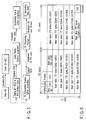
- FIG. 5 is a view for explaining the processing sequence for generating a recording data field.
- Data to be recorded on a data field of the information storage medium is called a Data frame, Scrambled frame, and Recording frame or Recorded data field in correspondence with signal process stages, as shown in FIG. 5.
- the Data frame consists of 2048 bytes, and has main data, a 4-byte data ID, 2-byte ID error detection code (IED), 6 reserved bytes, and a 4-byte error detection code (EDC).
- IED 2-byte ID error detection code
- EDC 4-byte error detection code
- the recording frames include parity data of outer-codes (PO) and parity data of inner-codes (PI).
- PO and PI are error correction codes respectively generated for each ECC block consisting of 32 scrambled frames.
- the recording data fields undergo 4/6 modulation.
- a sync code (SYNC) is appended to the head of every 91 bytes to form recording frames.
- Four recording data fields are recorded in one data field.
- FIG. 5 shows transition of data from main data to recording frames.
- FIG. 6 shows the format of the data frame.
- FIG. 7 shows the contents of the data ID in FIG. 6.
- This data ID consists of 4 bytes.
- the first byte (bits b31 to b24) stores data field information, and 3 bytes (bits b23 to b0) store a data field number.
- the data field information in an embossed data zone includes: information of a sector format type, tracking method, reflectance, recording type, area type, data type, layer number, and the like.
- the data field information in a rewritable data zone is as follows.
- FIG. 8 shows the contents of the data field number in FIG. 7. If an ECC block belongs to an embossed data zone, defect management area, or disc identification zone, the data field number describes a sector number. If an ECC block belongs to a data area, that data field number is "logical sector number (LSN) + 031000h". At this time, the ECC block contains user data.
- LSN logical sector number
- an ECC block belongs to the data area, but it does not contain any user data, i.e., it is an unused ECC block.
- Such case corresponds to one of the following three states: (1) the 0th to 3rd bits of the first sector are "0", and the subsequent sector describes a serially incremented field number; (2) this block describes a field number ranging from 00 0000h to 00 000Fh; (3) this block describes no data.
- the error detection code (IED) of the data ID will be described below.
- RSV 6-byte RSV will be explained below.
- the first byte of the RSV is used as seed information for scramble.
- the remaining 5 bytes are reserved (0h).
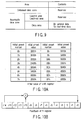
- FIGS. 10A and 10B are views for explaining an example of initial values of a shift register upon scrambling main data, and that shift register.
- FIG. 10A shows an example of initial values to be given to a feedback shift register upon generating a scrambled frame
- FIG. 10B shows the feedback shift register used to generate a scramble byte. In this case, 16 different preset values are prepared.
- Bits r7 (MSB) to r0 (LSB) are shifted by 8 bits and are used as a scramble byte.
- An initial preset number in FIG. 10A is equal to 4 bits (b7 (MSB) to b4 (LSB)) of the data ID.
- an initial value of r14 to r0 must be set to be an initial preset value in the table of FIG. 10A.
- An identical initial preset value is used for 16 successive data frames. Next, an initial preset value is switched, and the switched identical preset value is used to the next 16 successive data frames.
- ECC block The configuration of an ECC block will be described below (D) (E).
- FIG. 11 shows an ECC block.
- the ECC block is made up of 32 successive scrambled frames. 192 rows + 16 rows (column direction) and (172 + 10) ⁇ 2 columns (row direction) are arranged. Each of B0, 0, B1, 0, ... is one byte.
- PO and PI are error correction codes, i.e., parity data of outer-codes and parity data of inner-codes.
- FIG. 12 shows the scrambled frame allocation obtained by rewriting FIG. 11. Furthermore, this system handles (block 182 bytes ⁇ 207 bytes) as a pair. If L is assigned to respective scrambled frame numbers in the left ECC block, and R is assigned to those in the right ECC block, scrambled frames are allocated, as shown in FIG. 12. That is, left and right scrambled frames alternately appear in the left block, and right and left scrambled frames alternately appear in the right block.
- the ECC block is formed of 32 successive scrambled frames. Respective rows on the left half of an odd sector are replaced by those on the right half. 172 bytes ⁇ 192 rows are equal to 172 bytes ⁇ 12 rows ⁇ 32 scrambled frames to form an information field.
- 16-byte PO data is appended to 172 ⁇ 2 columns to form outer code RS (208, 192, 17).
- 10-byte PI (RS(182, 172, 11)) data is appended to 208 ⁇ 2 rows of the right and left blocks. PI data is also appended to PO rows.
- Numerals in frames indicate scrambled frame numbers, and suffices R and L indicate the right and left halves of the scrambled frames.
- PO and PI data shown in FIG. 11 are generated in the following sequence.
- This Bi,j is defined by: provided that The above polynomial of [Eq7] forms outer code RS (208, 192, 17) for 172 ⁇ 2 columns.
- This Bi,j is defined by: provided that provided that where ⁇ is the primitive root of the primitive polynomial.
- P(X) X 8 + X 4 + X 3 + X 2 + 1
- the above polynomials of [Eq9] and [Eq11] form inner code RS (182, 172, 11) for (208 ⁇ 2)/2 rows.
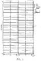
- FIG. 13 shows the state wherein parity data of outer-codes (PO) are interleaved to the left and right blocks.
- Bi,j as elements of a B matrix shown in FIG. 11 form 208 rows ⁇ 182 ⁇ 2 columns. This B matrix is interleaved between neighboring rows so that Bi,j are re-allocated as Bm,n.
- FIG. 13 shows 16 parity rows. That is, each of 16 parity rows is allocated every two recording frames. Therefore, a recording frame consisting of 12 rows has 12 rows + 1 row. After this row interleave, 13 rows ⁇ 182 bytes are referred to as a recording frame. Therefore, the ECC block after row interleave is made up of 32 recording frames. In one recording frame, six rows are present in each of the right and left blocks, as described in FIG. 12. Also, PO is allocated at different rows in the left block (182 ⁇ 208 bytes) and right block (182 ⁇ 208 bytes).
- FIG. 12 shows one complete ECC block. However, in actual data reproduction, such ECC blocks are successively input to an error correction processor. In order to improve the correction performance of such error correction process, the interleave scheme shown in FIG. 13 is adopted.
- FIGS. 14A and 14B show an example of the configuration of recorded data fields (even and odd fields).
- one ECC block is formed of right and left "small ECC blocks", and data of different PO groups (PO belonging to the left small ECC block or PO belonging to the right small ECC block) are alternately inserted for respective sectors.
- This embodiment is characterized in that the Sync frame structure is changed, as shown in FIGS. 14A and 14B, depending on whether the sector number of each sector which forms one ECC block, which specifies a plurality of different Sync frame structures in accordance with sectors that form the ECC block, is an even or odd number. That is, a structure in which data of different PO groups are alternately inserted for respective sectors (FIG. 13) is adopted.
- FIG. 15 is a view for explaining an example of the practical contents of a sync code.
- a sync code has two states, i.e., State0 and State1 in correspondence with the modulation rules in the embodiment of the present invention. For each state, four different sync codes “SY0" to “SY3" are set.
- the information recording/reproduction apparatus or information reproduction apparatus identifies the type of sync code by pattern matching upon reproducing information from the information storage medium. Since the number of types of sync codes is greatly reduced as in the embodiment of the present invention, the number of target patterns required for matching is reduced to simplify the process required for pattern matching, thus improving not only the processing efficiency but also the recognition speed.
- a sync code in the embodiment of the present invention is formed of the following parts.
- This part has a pattern common to all sync codes, and forms a fixed code area. By detecting this code, the allocation position of a sync code can be detected. More specifically, this part means the last 17 channel bits "01000 000000 001001" in each sync code shown in FIG. 15.
- This part forms a part of a variable code area, and stores a code which changes in correspondence with a State number upon modulation. This part corresponds to the first one channel bit in FIG. 15.
- This part stores a code used to identify each of types "SY0" to "SY3" in a sync code, and forms a part of a variable code area.
- This part corresponds to the 2nd to 7th channel bits in each sync code shown in FIG. 15. As will be described later, this code part allows to detect a relative position in a single sector from a combined pattern of successively detected three sync codes.
- the embodiment of the present invention adopts RLL(1, 9) of 4/6 modulation as the modulation method. That is, 4 bits are converted into 6 channel bits upon conversion, and the minimum value (d value) of the range of a "0" run is 1, and its maximum value (k value) is 9.
- d value the minimum value of the range of a "0" run
- k value its maximum value
- PRML Partial Response Maximum Likelihood
- the embodiment of the present invention is characterized in that only "SY0" of the four different sync codes shown in FIG. 15 is allocated at the first sync frame position in a sector, as shown in FIGS. 14A and 14B.
- SY0 the head position in a sector
- the head position extraction process in a sector can be greatly simplified.
- all combination patterns of three successive codes are different in a single sector.
- FIG. 16 is a view for explaining comparative example 1 of combination patterns (column direction) of successive sync codes (upon moving between sectors).
- the combination pattern of three sync codes in this case is (0, 1, 1) by arranging only their sync code numbers.
- the sync frame position "02" indicates the third sync frame position from the left in the uppermost row in the even recorded data field in FIG. 14A.
- a sync code at this sync frame position is "SY1".
- a sync code at the immediately preceding sync frame position is "SY1”
- the sixth row in FIG. 16 represents the number of changes in sync code number in pattern changes upon shifting the combination of three successive sync codes by one code.
- the central sync code remains the same (“1 ⁇ 1"), but the code before the central code changes like "0 ⁇ 1", and that after the central code changes like "1 ⁇ 2".
- the codes change at a total of "two positions", and the number of code changes between neighboring patterns is "2".
- a large characteristic feature of the present invention lies in that sync code numbers in a sector are arranged so that the number of code changes between neighboring patterns is 2 or more within the full latest sync frame number range from "00" to "25" (that is, sync code numbers in each combination pattern obtained by shifting a combination of three successive sync codes by one code change at least at two or more positions).
- FIG. 17 is a view for explaining comparative example 2 of combination patterns (column direction) of successive sync codes (upon extending across a guard area).
- a specific data structure of the read-only information storage medium, and additionally recordable and rewritable information storage media have guard areas between neighboring ECC blocks.
- the first sync code is allocated in a PA (Postamble) area in this guard area, and the sync code in that guard area is set to be "SY1", as shown in FIG. 17.
- the seventh row in each of FIGS. 16 and 17 represents the number of code changes upon shifting the combination of three successive sync codes by two codes.
- the sync code number after the central code remains unchanged (“1 ⁇ 1"), but the sync code number before the central code changes like "0 ⁇ 1", and the central sync code number changes like "1 ⁇ 2".
- the codes change at a total of "two positions", and the number of code changes upon shifting the combination by two codes is "2".
- sync code data are accurately detected in turn simultaneously with reproduction of frame data.
- neighboring patterns obtained by shifting the combination by one code are detected as combination patterns of three successive sync codes.
- sync code numbers change at least at two positions in the combination patterns of three successive sync codes, as shown in FIGS. 16 and 17. Therefore, if only one sync code number changes between neighboring combination patterns, it is highly likely that some sync codes (numbers) are erroneously detected or a tracking error has occurred.
- the sync timing can be reset by shifting it by one sync frame (by correcting the reproduction position).
- a frame shift amount upon occurrence of a frame shift is " ⁇ 1 sync frame" in most cases.
- most of frame shifts can be detected as long as a'pattern change situation upon shifting for one sync frame is determined.
- the sync code arrangement method according to the embodiment of the present invention is characterized in that:
- Upon occurrence of a tracking error it can be detected by checking continuity of data IDs shown in FIG. 6 or that of wobble address information (to be described later) (the continuity is disturbed when the tracking error has occurred).
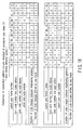
- FIG. 18 is a view for explaining an example of the relationship between the detected pattern contents and abnormal phenomenon contents upon detecting of an unexpected combination pattern of sync codes.
- a large characteristic feature of the embodiment of the present invention lies in that "frame shift" or "detection error of a sync code/tracking error" can be identified by determining whether or not the number of sync code number change positions in a pattern is only one.
- pattern change states in respective cases are summarized in the column direction (vertical direction).
- case 1 "frame shift” is determined when a detected pattern has two or more different sync code number change positions from the expected combination pattern, and matches a pattern shifted by ⁇ 1 sync frame from the expected pattern.
- case 2 "frame shift” is determined only when the following three states are detected at the same time: “the detected pattern has only one different sync code number change position from the expected pattern”, “the detected pattern matches a pattern shifted by ⁇ 1 sync frame from the expected pattern”, and "the detected pattern corresponds to one of (1, 1, 2), (1, 2, 1), (1, 2, 2), and (2, 1, 2)".
- the number of code changes upon shifting a combination of three successive sync codes is set to be two or more (FIGS. 16 to 18).
- the frame data size for one sync frame corresponds to half a line in the right and left small ECC blocks which form the ECC block shown in FIG. 13. Therefore, when frame data is assigned to a wrong position in the ECC block for one sync frame, the error correction performance considerably impairs, and such assignment error influences all data in the ECC block.
- the sync code arrangement so that the number of code changes upon shifting the combination of three successive sync codes by one code is two or more like in the embodiment of the present invention, even when a sync code number is erroneously detected due to dust or scratches attached to the surface of the information storage medium or small defects on a recording film (light reflection film), determination errors of a frame shift can be minimized, and a large error correction performance drop of the ECC block can be prevented.
- the embodiment of the present invention admits two different data structures of recording data on a read-only information storage medium (next-generation DVD-ROM), and allows the contents provider to select one of these structures depending on data contents to be recorded.
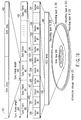
- FIG. 19 is a view for explaining an example of a data unit of recording data on an information storage medium.
- Information storage medium 221 in FIG. 19 is configured to record digital information on areas 401 (ECC blocks) partitioned by a plurality of sectors using the sync frame structure shown in FIGS. 14A to 17.
- data to be recorded on information storage medium 221 has a hierarchical structure of recording data shown in FIG. 19 independently of the type (read-only/additionally recordable/rewritable) of information storage medium 221.
- one ECC block 401 as the largest data unit that allows error detection or correction of data is made up of 32 sectors 230 to 241.
- Sectors 230 to 241 shown in FIG. 19 have the same contents as those of sectors 231 to 238 to be recorded for respective packs shown in FIG. 13.
- each of sectors 230 to 241 consists of 26 sync frames #0 420 to #24 429.
- One sync frame includes sync code 431 and sync data 432, as shown in FIG. 19.
- One sync frame contains data of 1116 channel bits (24 + 1092), as shown in FIGS. 14A and 14B, and sync frame length 433 as a physical distance required to record this one sync frame on information storage medium 211 is nearly constant all over the medium (when a change in physical distance for intra-zone synchronization is removed).
- a characteristic feature of the embodiment of the present invention also lies in that a plurality of different recording formats can be set even on a read-only information storage medium [corresponding to point (C) of invention]. More specifically, two different recording formats to be described in the first and second embodiments of read-only information storage media are available.
- FIGS. 20A and 20B are views for explaining the difference between the first and second embodiments by comparison when the embodiment of the present invention is applied to a read-only information storage medium.
- FIG. 20A shows the first embodiment, and ECC blocks #1 411 to #5 415 are successively recorded on information storage medium 221 to have no physical spaces between neighboring ECC blocks.
- the second embodiment is different from the first embodiment in that guard areas #1 441 to #8 448 are inserted between neighboring ECC blocks #1 411 to #8 418, as shown in FIG. 20B [corresponding to point (H) of invention].
- the physical length of each of guard areas #1 441 to #8 448 matches sync frame length 433.
- Each of lead-in and lead-out areas adopts a data structure that records data without any gaps.
- the identification flag is recorded in a disc identification zone in a rewritable data zone (although not shown).
- the recording format of the second embodiment of the read-only information storage medium according to the embodiment of the present invention adopts a structure that inserts guard areas #1 441 to #8 448 between neighboring ECC blocks #1 411 to #8 418, as shown in FIG. 20B [corresponding to point (C) of invention].
- the reproduction operation in conventional ROM media must read out an error correction block that contains a request data block first.
- a position where the designated block may be present is calculated and estimated based on, e.g., a block number difference or the like from the current position, thus starting a seek operation.
- read clocks are extracted from information data to attain channel bit synchronization, frame sync signal detection, and symbol synchronization, so as to read out symbol data, and a block number is then detected to confirm the designated block.
- ROM media reproduction only an RF signal specified by information pits is available as a detection signal. Hence, all processes such as disc rotation control, information linear velocity detection, and generation of channel bit read clocks as data read clocks are done using the RF signal. Since a recordable/reproducible medium has address information or the like as the goal of the embodiment of the present invention in a signal format different from the recording format of data information so as to designate a recording position, channel bit clock generation PLL or the like can detect a linear velocity or the like using such signal, and the oscillation frequency of PLL can be controlled to be in the neighborhood of an accurate channel bit clock frequency. For this reason, an optimal system that can shorten the PLL lockup time and can prevent runaway can be provided.
- ROM media cannot use a similar control system since such signal is not available.
- a system is built using, e.g., maximum code length (Tmax) and minimum code length (Tmin) signals of conventional information signals. That is, it is important for ROM media to attain a PLL lock state as early as possible, and a signal format for that purpose is demanded.
- Tmax maximum code length
- Tmin minimum code length
- the data/track structure of ROM media such as existing CD-ROMs, DVD-ROMs, and the like is determined in consideration of only the recording density, and that of recordable/reproducible media is then built. Hence, different data streams are adopted for respective media.
- the recording format of the second embodiment of the read-only information storage medium according to the embodiment of the present invention also has as its object to implement control similar to the reproduction process of recordable/reproducible media by adopting, even for ROM media, a structure in which guard areas #1 441 to #8 448 are inserted between neighboring ECC blocks #1 411 to #8 418, as shown in FIG. 20B, and inserting signals required for seek facility and lock facility of channel bit clock generation PLL in each guard area.
- FIG. 21 shows an example of a guard area on ROM media.
- the guard area is made up of sync code: SY1 and specific code: 1002.
- Specific code: 1002 contains an error correction ECC block number, Segment-NO, copyright protection signal, and other control information signals.
- Specific code: 1002 can be used to allocate special control signals which are not stored in a data area. Such specific control signals include, for example, a copyright protection signal, media unique information signal, and the like, and high system expandability can be guaranteed by assuring such specific information area.
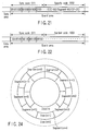
- FIG. 22 shows another example.
- the area of specific code: 1002 in FIG. 21 is used to allocate a random signal (random code 1003) that allows channel bit clock generation PLL to easily attain a lock state.
- VFO Variable Frequency Oscillator
- the area of random code 1003 in FIG. 22 is configured to introduce a random signal as a combination of limited code lengths obtained by omitting some code lengths on the shortest pit side which have poor reliability in PLL phase detection, and those on the longest pit side at which the number of times of detection becomes small. That is, a random signal based on runlength-limited codes is used.
- specific code: 1002 in FIG. 21 may be scrambled using a random signal from a random number generator, whose initial value is designated by a segment number. Upon modulating scramble data at that time to a recording signal, it is desirable to modify a modulation table to obtain a runlength-limited recording signal stream. With this process, coincidence of neighboring track patterns in the area of specific code: 1002 can be prevented as in the scramble process function applied to the data area of an existing DVD-ROM.
- FIG. 23 is a view for explaining examples of the data formats of various information storage media (read-only, additionally recordable, rewritable) by comparison.
- (a) and (b) transcribe the first and second embodiments of the read-only information storage medium shown in FIGS. 20A and 20B intact.
- guard areas each having the same length as sync frame length 433 are formed between neighboring ECC blocks #1 411 to #8 418, as in the second embodiment of the read-only information storage medium.
- the guard areas of the read-only information storage media and guard areas #2 452 to #8 458 of an additionally recordable information storage medium shown in (c) of FIG. 23 use different patterns of data (recording marks) to be recorded on each guard area.
- guard areas #2 442 to #8 448 of the read-only information storage medium shown in (b) of FIG. 23 and guard areas #2 462 to #8 468 of a rewritable information storage medium shown in (d) of FIG. 23 use different patterns of data (recording marks) to be recorded on each header area. In this way, the type of information storage medium 221 can be determined.
- the information additional recording and rewrite processes are executed for respective ECC blocks #1 411 to #8 418.
- the additionally recordable information storage medium is a write-once storage medium that allows a recording operation only once, and normally undergoes a continuous recording process.
- a method of recording a next data block after the previously recorded block by an additional recording scheme is adopted. For this reason, a term "additionally recordable information storage medium" is used in FIG. 23.
- a recording track groove is physically formed on a recording track, and is wobbled for the purpose of recording rate control, insertion of addressing information, and the like.
- the oscillation frequency of channel bit clock generation PLL can be controlled, and runaway of the oscillation frequency can be prevented in the processing operation such as variable speed reproduction.
- the additionally recordable information storage medium after recording is used as a read-only medium, coincidence of recording signal patterns between neighboring tracks must be avoided in anticipation of the adoption of the differential phase detection method as the tracking error detection method described in section [5].
- a guard area preferably adopts a structure that allows channel lock generation PLL to easily lock, i.e., the area of random code 1003 in FIG. 22 preferably stores a signal of given periods like a VFO signal.
- guard area 442 in (b) of FIG. 23, guard area 452 in (c), and guard area 462 in (d) adopt optimized data structures that consider the natures of the media.
- the header area of the read-only information storage medium preferably stores a pattern that allows easy linear velocity detection, and a lock facilitation signal of channel bit generation PLL based on a random signal.
- the header area of the additionally recordable information storage medium preferably stores a lock facilitation signal of channel bit generation PLL based on a random signal, which can cope with phase variation in the header area, since the oscillation frequency of channel bit clock generation PLL is prevented from running away by wobbling detection and can undergo neighborhood control.
- the rewritable information storage medium it is optimal for the rewritable information storage medium to adopt a VFO pattern of given periods as a PLL lock facilitation signal, and to use other header mark signals and the like.
- guard areas are used depending on the types of information storage media, media identification is facilitated. Also, a copyright protection system can improve the protection performance, since read-only and recordable media use different guard areas.
- FIG. 24 shows the zone structure of the rewritable information storage medium according to the embodiment of the present invention.
- the rewritable information storage medium according to the embodiment of the present invention adopts a zone structure, as shown in FIG. 24.
- reproduction linear velocity 5.6 m/s channel length: 0.086 ⁇ m track pitch: 0.34 ⁇ m channel frequency: 64.8 MHz
- recording data RF signal: (1, 7)RLL wobble carrier frequency: about 700 kHz (93T/wobble) modulation phase difference [deg]: ⁇ 90.0 segment/track: 12 to 29 segments zone: about 18 zones
- address information on a recordable information storage medium is recorded in advance using wobble modulation.
- the wobble modulation method phase modulation of ⁇ 90° (180°) is used, and an NRZ (Non Return to Zero) method is adopted.
- an L/G (Land and Groove) recording method is used for a rewritable information storage medium.
- a large characteristic feature of the embodiment of the present invention also lies in that the wobble modulation method is adopted in the L/G recording method.
- FIG. 25 is a view for explaining 180° phase modulation and the NRZ method in wobble modulation. A practical explanation will be given using FIG. 25.
- 1-address bit (or address symbol) area 511 is expressed by 8 or 12 wobbles, and the frequency, amplitude, and phase match throughout 1-address bit area 511.
- the same phase continues at a boundary (indicated by each "black triangle mark" in FIG. 25); when the address bit is inverted, a wobble pattern is inverted (180° phase shift).
- L/G recording adopts 180° ( ⁇ 90°) wobble phase modulation (FIG. 25)
- the rewritable information storage medium As information indicating addresses on information storage medium 221, the rewritable information storage medium according to the embodiment of the present invention has three different kinds of address information: zone number information as zone identification information, segment number information as segment address information, and track number information indicating track address information.
- a segment number means a number in a round
- a track number means a number in a zone.
- intra-zone identification information and segment address information of the address information assume identical values between neighboring tracks, but track address information assumes different address information values between neighboring tracks.
- FIG. 26 is a view for explaining the principle of generation of an unstable bit upon making wobble modulation in land (L)/groove (G) recording.
- L land
- G groove
- the embodiment of the present invention uses already known "gray codes” or special track codes newly invented in the embodiment of the present invention by improving the gray codes [corresponding to point (O) of invention] for the purpose of reducing the frequency of occurrence of unstable bit area 504.
- FIG. 27 shows an example of gray codes.
- the gray code is characterized in that "only 1 bit changes" (like alternating binary patterns) every time a decimal number changes by "1".
- FIG. 28 shows a special track code newly proposed by the embodiment of the present invention.
- This special track code is characterized in that "only 1 bit changes” every time a decimal value changes by "2" (track numbers m and m+2 change like alternating binary patterns), and for integer n, only the most significant bit changes between 2n and 2n+1 and all other lower bits match.
- the special track codes in the embodiment of the present invention are not limited to the above specific example.
- codes which are characterized in that "only 1 bit changes” every time a decimal value changes by "2" (track numbers m and m+2 change like alternating binary patterns), and an address bit changes while "holding a special relationship" between 2n and 2n+1 may be set.
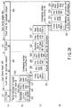
- FIG. 29 is a view for explaining an example of the recording method of rewritable data to be recorded on a rewritable information storage medium.
- FIG. 29 shows the recording format of rewritable data to be recorded on a rewritable information storage medium.
- (a) shows the same contents as those of (d) of FIG. 23 above.
- rewritable data is rewritten for respective ECC blocks.
- FIG. 29, (c) shows the rewritable data structure in a rewritable unit. Rewritable data is rewritten on an information storage medium by rewrite unit 531 of ECC block #2 information.
- the data contents of rewritable data 525 in ECC block #2 have a data structure of the same format independently of the types of media such as a read-only information storage medium ((a) and (b) of FIG. 23), additionally recordable information storage medium ((c) of FIG. 23), and the like, and data for 9672 bytes can be recorded. That is, the data contents of rewritable data 525 in ECC block #2 have the structure shown in FIG. 13. Each sector data which forms an ECC block is made up of 26 sync frames, as shown in FIG. 19 or FIGS. 14 A and 14B (data field structure).
- rewrite unit 531 of ECC block #2 As shown in (c) of FIG. 29, in rewrite unit 531 of ECC block #2 information, 2 bytes are assigned to copy-protection compatible copy information area 524 before rewritable data 525 in ECC block #2. Also, 3 bytes are set for pre-sync area 532 indicating the end position of a VFO area before area 524. VFO (Variable Frequency Oscillator) area 522 set for 35 bytes is used to attain synchronization upon reproduction of rewritable data 525. Immediately after rewritable data 525, postamble area 526 indicating the end position of rewritable data 525 is allocated.
- VFO Very Frequency Oscillator
- Front and rear guard areas 521 and 527 are respectively allocated at the leading and trailing end portions of rewrite unit 531 of ECC block #2 information.
- Front guard area 521 has 30 bytes + J
- rear guard area 527 has 22 bytes ⁇ J.
- "random shift” that changes the write start/end position of rewrite unit 531 of ECC block #2 information can be realized.
- a phase change recording film has a feature in that the characteristic deterioration of the recording film readily conspicuously occurs at the write start/end position of rewritable data. However, in the embodiment of the present invention, the characteristic deterioration of the phase change recording film can be prevented by the aforementioned random shift.
- FIG. 29 shows part 530 of a rewrite unit of ECC block #1 information
- (d) of FIG. 29 shows part 532 of a rewrite unit of ECC block #3 information.
- a characteristic feature of the embodiment of the present invention lies in that data are rewritten so that front and rear guard areas 521 and 527 partially overlap each other to form overlapping portions 541 and 542 upon rewriting [corresponding to point (I) of invention]. Since data are rewritten so that guard areas partially overlap each other, interlayer crosstalk on a single-sided, dual-recording layer recordable information storage medium can be removed.
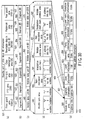
- FIG. 30 is a view for explaining an example of the wobble address format on the information storage medium according to the embodiment of the present invention.
- the address information recording format using wobble modulation on the recordable information storage medium according to the embodiment of the present invention will be explained below using FIG. 30.
- a large characteristic feature of the address information setting method using wobble modulation according to the embodiment of the present invention likes in that "assignment is made using the sync frame length shown in FIG. 18 as a unit".
- One sector is made up of 26 sync frames, as shown in FIGS. 14A and 14B, and one ECC block consists of 32 sectors, as can be seen from FIG. 13.
- a length for seven sync frames is assigned to that of each of wobble data units #0 560 to #16 576.
- Each of wobble data units #0 560 to #16 576 is formed of a modulated area for 16 wobbles and non-modulated area 590 or 591 for 68 wobbles.
- a large characteristic feature of the embodiment of the present invention lies in that non-modulated area 590 or 591 has a very large occupation ratio to the modulated area.
- modulation start mark 581 or 582 Upon transition from non-modulated area 590 or 591 to the modulated area, modulation start mark 581 or 582 is set using four wobbles. Immediately after detection of this modulation start mark 581 or 582, wobble-modulated wobble address area 586 or 587 appears. In order to extract wobble address information 610 in practice, wobble sync area 580 and wobble address areas 586 and 587 in wobble segments #0 550 to #6 556 except for non-modulated areas 590 and 591 and modulation start marks 581 and 582 are collected, as shown in (d) and (e) of FIG. 30, and are re-allocated, as shown in (e) of FIG. 30.
- wobble patterns of wobble sync area 580 and modulation start marks 581 and 582 are set. That is, wobble patterns which are never generated in wobble address areas 586 and 587 are set for wobble sync area 580 and modulation start marks 581 and 582, thus easily identifying the locations of wobble sync area 580 and modulation start marks 581 and 582.
- a full modulated area (for 16 wobbles) in one wobble data unit #9 560 is assigned to wobble sync area 580, thus facilitating detection of the start position of wobble address information 610 (the location of wobble sync area 580).
- wobble address information 610 The contents of wobble address information 610 are as follows.
- Each information means a track number in a zone, and groove track information 606 that settles an address on a groove (no unstable bit is included ⁇ an unstable bit is generated on a land) and land track information 607 that settles an address on a land (no unstable bit is included ⁇ an unstable bit is generated on a groove) are alternately recorded.
- track number information is recorded using gray codes shown in FIG. 27 or special track codes shown in FIG. 28.
- This information indicates a segment number in a track (within a round in information storage medium 221). If a segment number is counted from “0" as segment address information 601, a pattern "000000” as a run of "0"s for 6 bits appears in segment address information 601. In such case, it becomes difficult to detect the position of the boundary ("black triangle mark” portion) between neighboring address bit areas 511 shown in FIG. 25, and a bit shift that detects the position of the boundary between neighboring 1-address bit areas 511 while being shifted readily occurs. As a result, a determination error of wobble address information due to such bit shift occurs.
- the segmented number is counted from "000001".
- a characteristic feature of the embodiment of the present invention also lies in this point [corresponding to point (K) of invention].
- This information indicates a zone number in information storage medium 221, and records a value "n" of "Zone (n)" shown in FIG. 24.
- Information storage media 221 has recording layer A 222 and recording layer B 223 independently of its media type (read-only, additionally recordable, or rewritable), and has a "single-sided, dual-recording layer" structure that allows reproduction or recording/reproduction from one surface side.
- Information indicating if the recording layer which currently undergoes reproduction or recording corresponds to recording layer A 222 or B 223 is recording layer identification information 603, and is designated by a recording layer number.
- This information is set for error detection upon reproduction from wobble address information 610. Seventeen address bits from segment information 601 to reserved information 604 are individually summed up, and if the sum is an even number, "0" is set; if it is an odd number, "1" is set.
- each of wobble data units #0 560 to #16 576 is formed of a modulated area for 16 wobbles and non-modulated area 590 or 591 for 68 wobbles, and non-modulated area 590 or 591 has a very large occupation ratio to the modulated area.
- the precision and stability of extraction (generation) of the reference or recording reference clocks are improved.
- An area that includes monotone information 608 shown in (e) of FIG. 30 correspond to those of wobble data unit #16 576 and wobble data unit #15 (not shown) immediately before unit #16 in (c) of FIG. 30 in their entirety.
- no modulation start marks 581 and 582 are set in wobble data unit #16 576 and wobble data unit #15 (not shown) immediately before unit #16, which include this monotone information 608, and a non-modulated area with a uniform phase is formed.
- FIG. 31 is a view for explaining an example of the method of determining the sync frame position in one physical sector on the basis of the order of sync frame identification codes in sync codes.
- FIG. 32 shows a practical example upon determining the sync frame position from the order of sync frame identification codes (when the data fields shown in FIGS. 14A and 14B are adopted).
- FIG. 33 is a block diagram for explaining the arrangement of an information recording/reproduction apparatus according to the embodiment of the present invention.
- FIG. 34 is a block diagram for explaining an example of the detailed arrangement of a sync code position extraction unit (detection unit) in FIG. 33 and its peripheral components.
- FIG. 33 shows the arrangement of the information reproduction apparatus or information recording/reproduction apparatus according to the embodiment of the present invention.
- the channel bit spacing is reduced nearly to the utmost limit so as to attain higher density of the information storage medium.
- the embodiment of the present invention uses the PRML (Partial Response Maximum Likelihood) technique.
- a signal reproduced from information recording/reproduction unit 141 undergoes reproduction waveform correction by PR equalization circuit 130.
- A/D converter 169 samples the signal output from PR equalization circuit 130 in synchronism with the timings of reference clocks 198 sent from reference clock generation circuit 160 so as to convert that signal into digital data.
- the digital data then undergoes a Viterbi decoding process in Viterbi decoder 156.
- the data after the Viterbi decoding process is processed as data which is the same as the conventional data binarized by the slice level.
- the error rate of data after Viterbi decoding increases if the sampling timing of A/D converter deviates.
- the information reproduction apparatus or information recording/reproduction apparatus additionally comprises a sampling timing extraction circuit (a combination of Schmitt trigger binarization circuit 155 and PLL circuit 174).
- the information reproduction apparatus or information recording/reproduction apparatus is characterized in that a Schmitt trigger circuit is used as a binarization circuit.
- This Schmitt trigger circuit has a characteristic that provides a specific width (forward voltage value of a diode in practice) to the slice reference level for binarization, and binarizes a value only when that specific width is exceeded. For example, when the pattern "1010101010101010101010" is input, as described above, no binarization switching takes place since the signal amplitude is very small.
- the embodiment of the present invention adopts the NRZI (Non Return to Zero Invert) method, and "1" positions of the pattern match pit edges (boundaries).
- NRZI Non Return to Zero Invert
- PLL circuit 174 detects frequency and phase differences between the binary signal as the output from Schmitt trigger binarization circuit 155 and reference clock signal 198 sent from reference clock generation circuit 160, and changes the frequency and phase of its output clocks.
- Reference clock generation circuit 160 applies feedback control to (the frequency and phase of) reference clocks 198 to decrease the error rate after Viterbi decoding using the output signal from PLL circuit 174 and decoding characteristic information (information of the convergence length (distance to convergence) in a path metric memory in Viterbi decoder 156 although not shown) of Viterbi decoder 156.
- ECC encoding circuit 161, ECC decoding circuit 162, scramble circuit 157, and descramble circuit 159 in FIG. 33 execute processes for respective bytes.
- the modulated length is: 8n ⁇ m Therefore, when the data processing unit in these circuits is converted into a processing unit after modulation, since the processing unit of modulated sync frame data 106 is given by formula (11), the data size (channel bit size) of a sync code must be set to be an integer multiple of formula (11) upon aiming at integration of processes between the sync code and modulated sync frame data.
- a large characteristic feature of the embodiment of the present invention lies in that the size of sync code 110 is set to be: 8Nn ⁇ m to assure integration of processes between sync code 110 and modulated sync frame data 106.
- N in formula (12) means an integer value.
- the total data size of sync code 110 is: 12N Since the sync code size of the existing DVD is 32 channel bits, the processes are simplified and the reliability of position detection/information identification can be improved by setting the total data size of the sync code to be smaller than 32 channel bits in the embodiment of the present invention. Therefore, in the embodiment of the present invention, the total data size of the sync code is set to be 24 channel bits, as shown in FIG. 15.
- FIG. 34 is a block diagram for explaining the detailed structure associated with peripheral units of sync code position detection unit 145 shown in FIG. 33.
- FIG. 35 is a flow chart for explaining an example of the method of determining the sync frame position in a sector from the order of three successive sync codes.
- Output data of Viterbi decoder 156 in FIG. 33 shown in (b) of FIG. 31 is transferred to sync code position detection unit 145 (ST51 in FIG. 35), which detects the positions of sync codes 110 (ST52 in FIG. 35).
- detected sync codes 110 are sequentially stored in memory 175, as shown in (c) of FIG. 31, via control unit 143 (ST53 in FIG. 35).
- Control unit 143 If the positions of sync codes 110 are detected, only modulated sync frame data 106 can be extracted from the data output from Viterbi decoder 156, and can be transferred to shift register circuit 170 (ST54 in FIG. 35). Control unit 143 reads out history information of sync codes 110 recorded in memory 175 to identify the order of sync frame position identification codes (ST55 in FIG. 35). Control unit 143 then determines the position of modulated sync frame data 106 in a physical sector, which is temporarily saved in shift register circuit 170 (ST56 in FIG. 35).
- FIG. 36 is a flow chart for explaining an example of the method of detecting any abnormality (tracking error or the like) from the order of a plurality of sync codes in the information recording/reproduction apparatus according to the embodiment of the present invention.
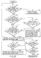
- FIG. 37 is a flow chart for explaining an example of the method of determining any abnormal phenomenon and taking a corresponding measure when the detection result of a combination pattern of sync codes is different from an expected pattern.
- the abnormality detection method using the detection result of a combination pattern of sync codes upon continuous reproduction will be described below using FIG. 36.
- the next combination pattern of sync codes, which are expected to be detected is estimated in advance in control unit 143, and is compared with an actually detected combination pattern of sync codes (ST66). If the comparison result indicates a mismatch, it is detected that some abnormality has occurred.
- FIG. 37 shows a phenomenon estimation method and measures when the detected combination pattern of sync codes is different from the previously estimated pattern.
- a pattern is estimated using the relationship explanatory view shown in FIG. 18.
- a characteristic feature of the process in FIG. 37 lies in that whether or not "the number of positions where the detected combination pattern of sync codes is different from the previously estimated pattern is one" is determined (ST3).
- an information storage medium which can display "high-definition" main picture information and high-image quality sub-picture information, can assure a large capacity, can assure high format compatibility, can assure high reliability of the PC data additional recording or rewrite process and address information reproduction process, can improve the reference clock extraction precision from wobble signals, can guarantee high-speed access, and can guarantee expandability to the single-sided, dual-recording layer structure, and an information reproduction apparatus which can stably reproduce data from that information storage medium or an information recording/reproduction apparatus which can stably record data on that information storage medium can be provided.
- FIG. 38 Effects obtained by combinations of various embodiments and/or their arrangements of the present invention will be described below with reference to FIG. 38.
- ⁇ marks indicate principal unique effects, and ⁇ marks indicate additional (secondary) effects.
- ⁇ 1> to ⁇ 15> in FIG. 38 correspond to the following item numbers ⁇ 1> to ⁇ 15>.
- FIG. 38 summarizes the above effects ⁇ 1> to ⁇ 15>.
- the sync code detection reliability can be improved while simplifying the sync code position detection process.
Landscapes
- Engineering & Computer Science (AREA)
- Signal Processing (AREA)
- Signal Processing For Digital Recording And Reproducing (AREA)
Applications Claiming Priority (2)
| Application Number | Priority Date | Filing Date | Title |
|---|---|---|---|
| JP2003045054A JP2004253099A (ja) | 2003-02-21 | 2003-02-21 | シンクフレーム構造、情報記憶媒体、情報記録方法、情報再生方法、および情報再生装置 |
| JP2003045054 | 2003-02-21 |
Publications (2)
| Publication Number | Publication Date |
|---|---|
| EP1450368A2 true EP1450368A2 (de) | 2004-08-25 |
| EP1450368A3 EP1450368A3 (de) | 2006-02-08 |
Family
ID=32733011
Family Applications (1)
| Application Number | Title | Priority Date | Filing Date |
|---|---|---|---|
| EP04002837A Withdrawn EP1450368A3 (de) | 2003-02-21 | 2004-02-09 | Synchronisationsrahmenstruktur, Informationsspeichermedium, Informationsaufzeichnungsverfahren, Informationswiedergabeverfahren und Informationswiedergabevorrichtung |
Country Status (6)
| Country | Link |
|---|---|
| US (10) | US7221641B2 (de) |
| EP (1) | EP1450368A3 (de) |
| JP (1) | JP2004253099A (de) |
| KR (1) | KR100665079B1 (de) |
| CN (1) | CN100409345C (de) |
| TW (1) | TW200501091A (de) |
Families Citing this family (18)
| Publication number | Priority date | Publication date | Assignee | Title |
|---|---|---|---|---|
| JP3803239B2 (ja) * | 2000-09-29 | 2006-08-02 | 株式会社ルネサステクノロジ | 誤り訂正符号化及び復号装置 |
| JP2004303395A (ja) * | 2003-03-14 | 2004-10-28 | Toshiba Corp | 光ディスクとその情報記録方法及び装置 |
| JP3967691B2 (ja) * | 2003-03-31 | 2007-08-29 | 株式会社東芝 | 情報記憶媒体と情報再生装置と情報記録再生装置 |
| JP4669243B2 (ja) * | 2004-07-23 | 2011-04-13 | ティアック株式会社 | 光ディスク装置 |
| US7336572B1 (en) * | 2004-08-19 | 2008-02-26 | Marvell International Ltd. | Detecting sync patterns for optical media |
| JP2006093754A (ja) * | 2004-09-21 | 2006-04-06 | Hitachi Ltd | 受信装置 |
| US7965601B2 (en) * | 2004-11-05 | 2011-06-21 | Nec Corporation | Disk recording/reproducing apparatus and disk recording method |
| KR100647295B1 (ko) * | 2004-11-10 | 2006-11-23 | 삼성전자주식회사 | 비디오 디코더에서의 인접 정보 처리 장치 및 방법과 그방법을 수행하기 위한 프로그램이 저장된 기록 매체 |
| JP2006164490A (ja) * | 2004-11-10 | 2006-06-22 | Victor Co Of Japan Ltd | 同期信号検出装置、同期信号検出方法、及び同期信号検出プログラム |
| JP4360345B2 (ja) * | 2005-05-11 | 2009-11-11 | 日本ビクター株式会社 | アドレス情報記録方法及び光記録媒体 |
| JP5021197B2 (ja) * | 2005-09-30 | 2012-09-05 | ソニー株式会社 | ディスク状記録媒体及びその製造方法、ディスク記録方法及び装置、並びにディスク再生方法及び装置 |
| JP4910807B2 (ja) * | 2006-03-23 | 2012-04-04 | 富士通セミコンダクター株式会社 | 再生装置及び再生方法 |
| JP2008310896A (ja) * | 2007-06-15 | 2008-12-25 | Spansion Llc | 不揮発性記憶装置、不揮発性記憶システムおよび不揮発性記憶装置の制御方法 |
| KR20090091023A (ko) * | 2008-02-22 | 2009-08-26 | 톰슨 라이센싱 | 채널 검출을 위한 방법 및 장치 |
| JP4764932B2 (ja) | 2009-02-03 | 2011-09-07 | 株式会社日立製作所 | 再生信号の評価方法および光ディスク装置 |
| CN102598133A (zh) * | 2009-11-06 | 2012-07-18 | 日本先锋公司 | 信息记录介质、信息记录装置以及信息重放装置 |
| US20120243602A1 (en) * | 2010-09-23 | 2012-09-27 | Qualcomm Incorporated | Method and apparatus for pipelined slicing for wireless display |
| CN111950434B (zh) * | 2020-08-07 | 2022-06-17 | 武汉中海庭数据技术有限公司 | 一种基于离散点扫描的车道线结构化方法及系统 |
Family Cites Families (31)
| Publication number | Priority date | Publication date | Assignee | Title |
|---|---|---|---|---|
| JP2786810B2 (ja) | 1994-03-16 | 1998-08-13 | 株式会社東芝 | 光ディスクおよびその信号記録装置ならびに信号再生装置 |
| JP3702015B2 (ja) | 1995-11-02 | 2005-10-05 | 株式会社東芝 | フレーム番号修正装置及び方法 |
| JP3103505B2 (ja) * | 1996-06-26 | 2000-10-30 | 三菱電機株式会社 | 光ディスク及び光ディスク駆動装置 |
| JP3562544B2 (ja) * | 1996-08-13 | 2004-09-08 | ソニー株式会社 | 復号化装置および復号化方法 |
| EP1271490B1 (de) * | 1996-10-23 | 2011-12-21 | Panasonic Corporation | Optische Platte |
| JP3956417B2 (ja) * | 1997-02-28 | 2007-08-08 | ソニー株式会社 | ディスク装置及びディスク再生方法 |
| US6061399A (en) | 1997-05-28 | 2000-05-09 | Sarnoff Corporation | Method and apparatus for information stream frame synchronization |
| JP3814966B2 (ja) | 1997-08-14 | 2006-08-30 | ソニー株式会社 | 記録媒体、データ伝送装置、データ受信装置及び光ディスク装置 |
| JPH1168750A (ja) | 1997-08-22 | 1999-03-09 | Nec Corp | ネットワーク管理システム |
| US6317397B1 (en) * | 1997-11-17 | 2001-11-13 | Matsushita Electric Industrial Co., Ltd. | Data recording medium, data recording apparatus, data reproducing apparatus and method |
| JPH11213626A (ja) * | 1998-01-21 | 1999-08-06 | Toshiba Corp | データ記録媒体とデータ記録装置とデータ再生装置 |
| BR9906671A (pt) * | 1998-08-04 | 2000-08-29 | Koninkl Philips Eletronics N V | Disco óptico, aparelho de gravação para gravar dados sobre o mesmo, e, dispositivo de leitura para efetuar a leitura de dados de um disco óptico |
| JP4010074B2 (ja) * | 1999-04-12 | 2007-11-21 | ソニー株式会社 | 磁気記録再生方法及び装置 |
| WO2001009890A1 (en) * | 1999-07-29 | 2001-02-08 | Matsushita Electric Industrial Co., Ltd. | Information recording/reproducing device using optical disk and method therefor and information recording system and information recording method |
| JP2001155346A (ja) * | 1999-11-26 | 2001-06-08 | Toshiba Corp | 情報記録媒体、情報記録装置、情報記録方法、情報再生装置、情報再生方法 |
| JP3954280B2 (ja) * | 2000-05-23 | 2007-08-08 | 株式会社東芝 | 光ディスクと再生方法と再生装置 |
| WO2002005277A2 (en) * | 2000-07-11 | 2002-01-17 | Matsushita Electric Industrial Co., Ltd. | Information recording medium, information recording apparatus, information recording method, information reproduction apparatus and information reproduction method |
| JP2002093060A (ja) * | 2000-07-11 | 2002-03-29 | Matsushita Electric Ind Co Ltd | 情報記録媒体、情報記録装置、情報記録方法、情報再生装置および情報再生方法 |
| KR100713094B1 (ko) * | 2000-12-26 | 2007-05-02 | 파이오니아 가부시키가이샤 | 정보 기록 매체, 및 정보 재생 장치 및 방법 |
| JP3708483B2 (ja) * | 2000-12-26 | 2005-10-19 | パイオニア株式会社 | 情報記録媒体、情報記録装置及び情報記録方法 |
| JP2002260339A (ja) * | 2001-02-28 | 2002-09-13 | Pioneer Electronic Corp | 記録可能な情報記録媒体、再生専用の情報記録媒体及び不正コピー防止方法 |
| JP2002372472A (ja) | 2001-06-13 | 2002-12-26 | Kyowa Electron Instr Co Ltd | 光ファイバを用いた物理量検出装置および物理量検出方法 |
| JP3964634B2 (ja) * | 2001-06-14 | 2007-08-22 | 株式会社東芝 | 同期コード生成方法、情報記録方法、情報再生方法、情報再生装置及び情報記憶媒体 |
| JP2003059193A (ja) | 2001-08-10 | 2003-02-28 | Hitachi Ltd | デジタルデータ記録媒体に対する識別データの記録方法及び記録再生装置 |
| TW561748B (en) | 2001-09-07 | 2003-11-11 | Inst Information Industry | Medium access control method for QoS using wireless dynamic control of frame granularity for ATM network |
| JP3559540B2 (ja) * | 2001-09-07 | 2004-09-02 | 株式会社東芝 | 多目的情報記憶媒体及び記憶方法及び再生方法及び再生装置 |
| JP2003085898A (ja) * | 2001-09-12 | 2003-03-20 | Toshiba Corp | 情報記憶媒体、情報記録装置、情報記録方法、情報再生装置、及び情報再生装置 |
| KR100833227B1 (ko) * | 2001-12-17 | 2008-05-28 | 삼성전자주식회사 | 광 기록매체에 데이터를 기록하는 방법 및 장치 |
| EP1571664A3 (de) * | 2002-06-05 | 2010-03-24 | Lg Electronics Inc. | Struktur eines Verknüpfungsbereichs, die auf einem hochdichten Nur-Lese-Aufzeichnungsmedium ausgebildet wird, und Herstellungs-/Reproduktionsverfahren und -Vorrichtung dafür |
| JP3889365B2 (ja) * | 2002-08-12 | 2007-03-07 | パイオニア株式会社 | 光学式記録媒体、記録装置、記録方法及び光学式記録媒体の製造方法 |
| US7042372B2 (en) * | 2002-10-31 | 2006-05-09 | Hewlett-Packard Development Company, L.P. | Encoding information in codes identifying beginning of regions of data |
-
2003
- 2003-02-21 JP JP2003045054A patent/JP2004253099A/ja active Pending
-
2004
- 2004-02-06 TW TW093102845A patent/TW200501091A/zh unknown
- 2004-02-09 EP EP04002837A patent/EP1450368A3/de not_active Withdrawn
- 2004-02-18 KR KR1020040010604A patent/KR100665079B1/ko not_active Expired - Fee Related
- 2004-02-20 CN CNB200410005848XA patent/CN100409345C/zh not_active Expired - Fee Related
- 2004-02-20 US US10/781,990 patent/US7221641B2/en not_active Expired - Fee Related
-
2006
- 2006-11-27 US US11/563,471 patent/US7440389B2/en not_active Expired - Fee Related
- 2006-11-27 US US11/563,461 patent/US7269122B2/en not_active Expired - Fee Related
- 2006-11-27 US US11/563,487 patent/US7317679B2/en not_active Expired - Fee Related
- 2006-11-27 US US11/563,431 patent/US7313082B2/en not_active Expired - Fee Related
- 2006-11-27 US US11/563,458 patent/US7233561B2/en not_active Expired - Fee Related
- 2006-11-27 US US11/563,472 patent/US7286465B2/en not_active Expired - Fee Related
- 2006-11-28 US US11/563,845 patent/US20070086323A1/en not_active Abandoned
- 2006-11-28 US US11/563,871 patent/US7385910B2/en not_active Expired - Fee Related
- 2006-11-28 US US11/563,826 patent/US7359296B2/en not_active Expired - Fee Related
Also Published As
| Publication number | Publication date |
|---|---|
| US7359296B2 (en) | 2008-04-15 |
| US20070086323A1 (en) | 2007-04-19 |
| US20070086313A1 (en) | 2007-04-19 |
| US7233561B2 (en) | 2007-06-19 |
| CN1542814A (zh) | 2004-11-03 |
| US7221641B2 (en) | 2007-05-22 |
| US20040252606A1 (en) | 2004-12-16 |
| US20070086314A1 (en) | 2007-04-19 |
| US20070086312A1 (en) | 2007-04-19 |
| TW200501091A (en) | 2005-01-01 |
| US7313082B2 (en) | 2007-12-25 |
| US7440389B2 (en) | 2008-10-21 |
| US20070097843A1 (en) | 2007-05-03 |
| US20070097840A1 (en) | 2007-05-03 |
| KR20040075731A (ko) | 2004-08-30 |
| US20070147211A1 (en) | 2007-06-28 |
| US20070086321A1 (en) | 2007-04-19 |
| JP2004253099A (ja) | 2004-09-09 |
| EP1450368A3 (de) | 2006-02-08 |
| US20070097839A1 (en) | 2007-05-03 |
| US7269122B2 (en) | 2007-09-11 |
| US7385910B2 (en) | 2008-06-10 |
| US7317679B2 (en) | 2008-01-08 |
| KR100665079B1 (ko) | 2007-01-09 |
| US7286465B2 (en) | 2007-10-23 |
| CN100409345C (zh) | 2008-08-06 |
Similar Documents
| Publication | Publication Date | Title |
|---|---|---|
| KR100557722B1 (ko) | 정보 기록 매체, 정보 재생 장치 및 정보 기록 재생 장치 | |
| US7221641B2 (en) | Sync frame structure, information storage medium, information recording method, information reproduction method, information reproduction apparatus | |
| US7319654B2 (en) | Optical disk, optical disk recording method and optical disk apparatus | |
| JP4054045B2 (ja) | 情報記憶媒体、情報記録方法、情報再生方法、および情報再生装置 | |
| JP3984176B2 (ja) | 情報記憶媒体と情報記録方法と情報再生方法と情報再生装置 | |
| JP4150023B2 (ja) | 情報記録媒体、情報記録方法及び再生方法、情報再生装置 | |
| JP4150022B2 (ja) | 情報記録媒体と情報記録方法と情報記録装置と情報再生方法 | |
| JP4150024B2 (ja) | 情報記録媒体、情報記録方法及び再生方法 | |
| JP4150021B2 (ja) | 情報記録媒体、情報記録方法及び再生方法 | |
| JP2007328911A (ja) | 情報記憶媒体、情報記録方法、情報再生方法、および情報再生装置 | |
| JP4006016B2 (ja) | 情報記憶媒体、情報記録方法及び情報再生方法 | |
| JP2008010147A (ja) | 情報記録媒体と情報記録方法と情報再生方法 | |
| JP2007311024A (ja) | 情報記憶媒体、情報記録方法及び情報再生方法 | |
| JP2008112571A (ja) | 情報記憶媒体、情報記録方法及び情報再生方法 |
Legal Events
| Date | Code | Title | Description |
|---|---|---|---|
| PUAI | Public reference made under article 153(3) epc to a published international application that has entered the european phase |
Free format text: ORIGINAL CODE: 0009012 |
|
| 17P | Request for examination filed |
Effective date: 20040209 |
|
| AK | Designated contracting states |
Kind code of ref document: A2 Designated state(s): AT BE BG CH CY CZ DE DK EE ES FI FR GB GR HU IE IT LI LU MC NL PT RO SE SI SK TR |
|
| AX | Request for extension of the european patent |
Extension state: AL LT LV MK |
|
| PUAL | Search report despatched |
Free format text: ORIGINAL CODE: 0009013 |
|
| AK | Designated contracting states |
Kind code of ref document: A3 Designated state(s): AT BE BG CH CY CZ DE DK EE ES FI FR GB GR HU IE IT LI LU MC NL PT RO SE SI SK TR |
|
| AX | Request for extension of the european patent |
Extension state: AL LT LV MK |
|
| RIC1 | Information provided on ipc code assigned before grant |
Ipc: G11B 27/00 20060101ALI20051221BHEP Ipc: G11B 20/00 20060101ALI20051221BHEP Ipc: G11B 20/18 20060101AFI20051221BHEP |
|
| AKX | Designation fees paid |
Designated state(s): AT BE BG CH CY CZ DE DK EE ES FI FR GB GR HU IE IT LI LU MC NL PT RO SE SI SK TR |
|
| 17Q | First examination report despatched |
Effective date: 20080516 |
|
| STAA | Information on the status of an ep patent application or granted ep patent |
Free format text: STATUS: THE APPLICATION IS DEEMED TO BE WITHDRAWN |
|
| 18D | Application deemed to be withdrawn |
Effective date: 20080927 |