EP1450082A2 - Druckbegrenzungsventil - Google Patents
Druckbegrenzungsventil Download PDFInfo
- Publication number
- EP1450082A2 EP1450082A2 EP04002128A EP04002128A EP1450082A2 EP 1450082 A2 EP1450082 A2 EP 1450082A2 EP 04002128 A EP04002128 A EP 04002128A EP 04002128 A EP04002128 A EP 04002128A EP 1450082 A2 EP1450082 A2 EP 1450082A2
- Authority
- EP
- European Patent Office
- Prior art keywords
- pressure
- piston
- valve
- valve body
- pressure limiting
- Prior art date
- Legal status (The legal status is an assumption and is not a legal conclusion. Google has not performed a legal analysis and makes no representation as to the accuracy of the status listed.)
- Granted
Links
Images
Classifications
-
- G—PHYSICS
- G05—CONTROLLING; REGULATING
- G05D—SYSTEMS FOR CONTROLLING OR REGULATING NON-ELECTRIC VARIABLES
- G05D16/00—Control of fluid pressure
- G05D16/14—Control of fluid pressure with auxiliary non-electric power
- G05D16/16—Control of fluid pressure with auxiliary non-electric power derived from the controlled fluid
- G05D16/166—Control of fluid pressure with auxiliary non-electric power derived from the controlled fluid using pistons within the main valve
-
- F—MECHANICAL ENGINEERING; LIGHTING; HEATING; WEAPONS; BLASTING
- F16—ENGINEERING ELEMENTS AND UNITS; GENERAL MEASURES FOR PRODUCING AND MAINTAINING EFFECTIVE FUNCTIONING OF MACHINES OR INSTALLATIONS; THERMAL INSULATION IN GENERAL
- F16K—VALVES; TAPS; COCKS; ACTUATING-FLOATS; DEVICES FOR VENTING OR AERATING
- F16K1/00—Lift valves or globe valves, i.e. cut-off apparatus with closure members having at least a component of their opening and closing motion perpendicular to the closing faces
- F16K1/32—Details
- F16K1/34—Cutting-off parts, e.g. valve members, seats
- F16K1/36—Valve members
- F16K1/38—Valve members of conical shape
- F16K1/385—Valve members of conical shape contacting in the closed position, over a substantial axial length, a seat surface having the same inclination
-
- G—PHYSICS
- G05—CONTROLLING; REGULATING
- G05D—SYSTEMS FOR CONTROLLING OR REGULATING NON-ELECTRIC VARIABLES
- G05D16/00—Control of fluid pressure
- G05D16/04—Control of fluid pressure without auxiliary power
- G05D16/10—Control of fluid pressure without auxiliary power the sensing element being a piston or plunger
-
- Y—GENERAL TAGGING OF NEW TECHNOLOGICAL DEVELOPMENTS; GENERAL TAGGING OF CROSS-SECTIONAL TECHNOLOGIES SPANNING OVER SEVERAL SECTIONS OF THE IPC; TECHNICAL SUBJECTS COVERED BY FORMER USPC CROSS-REFERENCE ART COLLECTIONS [XRACs] AND DIGESTS
- Y10—TECHNICAL SUBJECTS COVERED BY FORMER USPC
- Y10T—TECHNICAL SUBJECTS COVERED BY FORMER US CLASSIFICATION
- Y10T137/00—Fluid handling
- Y10T137/7722—Line condition change responsive valves
- Y10T137/7758—Pilot or servo controlled
- Y10T137/7762—Fluid pressure type
- Y10T137/7764—Choked or throttled pressure type
Definitions
- the present invention relates to a pressure relief valve according to the preamble of claim 1.
- Such pressure relief valves are preferably found in high pressure units Use, such as high-pressure spray guns or the like, in which the medium, preferably water or a comparable medium under a system pressure e.g.> 1000 bar.
- Pressure relief valves are used, both without and with are equipped with a pilot valve. In any case, to limit the pressure Energy store provided, one directly or indirectly on the valve body exerts predetermined pressure.
- the known pilot valves are designed so that the control pressure on Valve body is applied, is generated by separate throttles or nozzles medium is led out of the input channel into control lines while reducing the pressure will act on the one hand on the valve body and on the other hand on one Control unit with, for example, a pilot cone on which the Lift mechanism pressure is applied.
- the energy accumulator can consist, for example, of a pneumatic cylinder, whose air pressure is adjustable.
- an electromagnet as the energy store or a compression spring, the force of which can also be adjusted.
- the known pressure relief valves are not suitable for multiple parallel connections to a media source regardless of the number of the switched on or switched off consumers, at the respective switched on consumers to ensure a constant outlet pressure. Naturally, this leads to practice often leads to an unsatisfactory work result.
- the present invention is therefore based on the object of a pressure control valve the generic type to develop so that it is structurally simple is constructed and can be manufactured and operated more cost-effectively and its usability is improved.
- the piston is preferably completely surrounded by a sealing ring, which lies firmly in the valve body and its inner wall as well as the Sheath of the piston forms a limit for the throttle gap.
- this sealing ring is made of one wear-resistant material, preferably a hard metal, as well like the piston.
- the valve body is tapered towards its free end and centered in a valve seat.
- the invention leads to the fact that when several connected Consumers to a common system pressure source, independently of how many consumers are in operation or switched off, always a constant There is pressure of the medium at the outlet channel of each consumer.
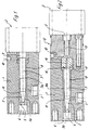
- valve housing represents, which has a valve housing 1 to which an energy accumulator 2, for example in the form of a pneumatic cylinder.
- valve body 5 In the valve housing 1, a valve body 5 is provided, which together with a Piston 7 forms a structural unit, which in turn is opposite to the valve body 5 lying end face by a piston 9 of the energy accumulator 2 with a predetermined pressure is applied.
- the valve body 5 is conical and is centered in a valve seat 6, in the case of operation without contact to form a gap 5a, the recording of the valve seat 6 for the valve body 5 at its inclination and contour is adjusted.
- an input channel 3 is introduced through which a pressurized system fluid medium, preferably water, can be supplied, the input channel 3 in a pressure chamber 11 opens.
- a pressurized system fluid medium preferably water
- the piston 7 is axial with little play in a fixed sealing sleeve 8 slidably supported, wherein a throttle gap 7a is formed by the game, the through the inner surface of the sealing sleeve 8 and the outer surface of the piston 7 is limited.
- the pressure chamber 11 is in the transition area between the. Valve body 5 and the piston 7 arranged so that both the gap 5a and the throttle gap 7a related to it.
- the pressure relief valve in addition, a pilot valve 12, which is located between the energy accumulator 2 and the valve housing 1 is arranged.
- This pilot valve 12 includes a receiving part 15, which is in the valve housing 1 is stored and which forms a boundary surface for a pressure chamber 14, on the other hand through the end face of the piston 7 and laterally through the inner wall the sealing sleeve 8 is limited. Concentric to the piston 7 extends in the receiving part 15 a bore 16 starting from the pressure chamber 14, the opposite lying end by a control cone connected to the pressure piston 9 13 is closed, the closure pressure by the adjustable pressure the energy accumulator 2 is determined.
Abstract
Description
- Figur 1
- ein Ausführungsbeispiel der Erfindung in einer geschnittenen Seitenansicht,
- Figur 2
- ein weiteres Ausführungsbeispiel der Erfindung, ebenfalls als geschnittene Seitenansicht dargestellt.
- 1
- Ventilgehäuse
- 2
- Kraftspeicher
- 3
- Eingangskanal
- 4
- Auslaßkanal
- 5
- Ventilkörper
- 5a
- Spalt
- 6
- Ventilsitz
- 7
- Kolben
- 7a
- Drosselspalt
- 8
- Dichtungshülse
- 9
- Druckkolben
- 10
- Leckagebohrung
- 11
- Druckkammer
- 12
- Vorsteuerventil
- 13
- Steuerkegel
- 14
- Druckraum
- 15
- Aufnahmeteil
- 16
- Bohrung
Claims (11)
- Druckbegrenzungsventil für ein unter Systemdruck stehendes fluides Medium, mit einem Ventilgehäuse (1), in dem ein Eingangskanal (3) und ein damit in Verbindung stehender Ausgangskanal (4) für das Medium vorgesehen sind, wobei der Mediumdurchfluß durch einen axial bewegbaren, mit einem Kraftspeicher (2) in Wirkverbindung stehenden Ventilkörper (5) im Zusammenspiel mit einem Ventilsitz (6) regelbar ist, dadurch gekennzeichnet, daß ein sich an den Ventilkörper (5) koaxial anschließender Kolben (7) mantelseitig einen Drosselspalt (8a) begrenzt, der mit dem Eingangskanal (3) in Verbindung steht und über den Kraftspeicher (2) direkt oder indirekt mit Druck beaufschlagbar ist.
- Druckbegrenzungsventil nach Anspruch 1, bei dem zwischen dem Ventilgehäuse (1) und dem Kraftspeicher (2) ein Vorsteuerventil (12) angeordnet ist, dadurch gekennzeichnet, daß das Vorsteuerventil (12) auf der dem Ventilkörper (5) abgewandten Seite des Kolbens (7) einen Druckraum (14) aufweist, in den der Drosselspalt (8a)mündet und der neben der Stirnfläche des Kolbens (7) durch ein gegenüber liegendes Aufnahmeteil (15) und seitlich durch die Innenwandung der Dichtungshülse (8) begrenzt ist.
- Druckbegrenzungsventil nach Anspruch 1 oder 2, dadurch gekennzeichnet, daß im Übergangsbereich zwischen dem Ventilkörper (5) und dem Kolben (7) eine Druckkammer (11) vorgesehen ist, in die der Eingangskanal (3) mündet.
- Druckbegrenzungsventil nach Anspruch 1 oder 2, dadurch gekennzeichnet, daß der Eingangskanal (3) quer zur Längsachse der Baueinheit Ventilkörper (5)/Kolben (7) angeordnet ist.
- Druckbegrenzungsventil nach Anspruch 1, dadurch gekennzeichnet, daß der Ventilkörper (5) in Betriebsstellung unter Bildung eines Spaltes (5a) in einem Ventilsitz (6) zentriert angeordnet ist.
- Druckbegrenzungsventil nach Anspruch 1, dadurch gekennzeichnet, daß der Ventilkörper (5) zu seiner dem Kolben (7) abgewandten Seite hin sich verjüngend ausgebildet ist.
- Druckbegrenzungsventil nach Anspruch 1, dadurch gekennzeichnet, daß der Kolben (7) mantelseitig von einer feststehenden Dichtungshülse (8) umschlossen ist.
- Druckbegrenzungsventil nach einem der Ansprüche 1 bis 7, dadurch gekennzeichnet, daß der Kolben (7) und die Dichtungshülse (8) aus einem verschleißfesten Material, vorzugsweise aus Hartmetall, gebildet sind.
- Druckbegrenzungsventil nach Anspruch 1, dadurch gekennzeichnet, daß zur Abführung des durch den Drosselspalt (7a) geführten Mediums im Ventilgehäuse (1) eine Leckagebohrung (10) vorgesehen ist.
- Druckbegrenzungsventil nach Anspruch 2, dadurch gekennzeichnet, daß in dem Aufnahmeteil (15) eine mit dem Druckraum (14) in Verbindung stehende Bohrung (16) angeordnet ist, die andererseits durch einen Steuerkegel (13), der mit dem Kraftspeicher (2) verbunden ist, verschließbar ist.
- Druckbegrenzungsventil nach einem der Ansprüche 1 bis 10, dadurch gekennzeichnet, daß die Leckagebohrung (10) in dem dem Anlagebereich des Steuerkegels (13) am Aufnahmeteil (15) benachbarten Bereich angeordnet ist.
Applications Claiming Priority (2)
| Application Number | Priority Date | Filing Date | Title |
|---|---|---|---|
| DE10306927 | 2003-02-19 | ||
| DE2003106927 DE10306927A1 (de) | 2003-02-19 | 2003-02-19 | Druckbegrenzungsventil |
Publications (3)
| Publication Number | Publication Date |
|---|---|
| EP1450082A2 true EP1450082A2 (de) | 2004-08-25 |
| EP1450082A3 EP1450082A3 (de) | 2005-03-23 |
| EP1450082B1 EP1450082B1 (de) | 2006-08-09 |
Family
ID=32731047
Family Applications (1)
| Application Number | Title | Priority Date | Filing Date |
|---|---|---|---|
| EP20040002128 Expired - Lifetime EP1450082B1 (de) | 2003-02-19 | 2004-01-31 | Druckbegrenzungsventil |
Country Status (7)
| Country | Link |
|---|---|
| US (1) | US20040173261A1 (de) |
| EP (1) | EP1450082B1 (de) |
| JP (1) | JP2004263868A (de) |
| AT (1) | ATE335947T1 (de) |
| AU (1) | AU2004200584A1 (de) |
| DE (2) | DE10306927A1 (de) |
| ES (1) | ES2266928T3 (de) |
Cited By (2)
| Publication number | Priority date | Publication date | Assignee | Title |
|---|---|---|---|---|
| CN107504202A (zh) * | 2017-10-17 | 2017-12-22 | 兰州理工大学 | 一种阀芯带有节流槽的抗污染耐撞击液压锥阀 |
| CN110030389A (zh) * | 2019-05-06 | 2019-07-19 | 西南石油大学 | 一种笼套式节流阀 |
Families Citing this family (9)
| Publication number | Priority date | Publication date | Assignee | Title |
|---|---|---|---|---|
| JP4654266B2 (ja) * | 2008-05-14 | 2011-03-16 | 株式会社群馬コイケ | ネブライザー |
| US8833384B2 (en) | 2012-08-06 | 2014-09-16 | Schneider Electric Buildings, Llc | Advanced valve actuation system with integral freeze protection |
| US9534795B2 (en) | 2012-10-05 | 2017-01-03 | Schneider Electric Buildings, Llc | Advanced valve actuator with remote location flow reset |
| US10295080B2 (en) | 2012-12-11 | 2019-05-21 | Schneider Electric Buildings, Llc | Fast attachment open end direct mount damper and valve actuator |
| EP2971901B1 (de) | 2013-03-15 | 2018-10-17 | Schneider Electric Buildings LLC | Erweitertes ventilstellglied mit integrierter energiedosierung |
| US9658628B2 (en) | 2013-03-15 | 2017-05-23 | Schneider Electric Buildings, Llc | Advanced valve actuator with true flow feedback |
| CN105134983B (zh) * | 2015-09-07 | 2017-12-26 | 赣州鑫亿化工有限公司 | 一种带雾化喷嘴的阀门 |
| CN108361404B (zh) * | 2018-02-09 | 2019-05-07 | 东北石油大学 | 一种远程液压控制高压调节阀 |
| DE102020112308A1 (de) | 2020-05-06 | 2021-11-11 | Hammelmann GmbH | Druckregelventil |
Citations (8)
| Publication number | Priority date | Publication date | Assignee | Title |
|---|---|---|---|---|
| DE1203991B (de) * | 1963-06-27 | 1965-10-28 | Bosch Gmbh Robert | Druckregelventil |
| GB1037696A (en) * | 1962-06-05 | 1966-08-03 | Danfoss As | Improvements in or relating to pressure control valves |
| US3604446A (en) * | 1969-05-26 | 1971-09-14 | Garrett Corp | Valve |
| US4009860A (en) * | 1974-05-18 | 1977-03-01 | Woma-Apparatebau Wolfgang Maasberg & Co. Gmbh | Shutoff valve for high-pressure spray guns |
| DE7731626U1 (de) * | 1977-10-13 | 1978-02-23 | Alfred Kaercher Gmbh & Co, 7057 Winnenden | Ueberstroemventil |
| US4349154A (en) * | 1979-11-01 | 1982-09-14 | Butterworth, Inc. | Power assisted dump valve |
| EP0475754A2 (de) * | 1990-09-13 | 1992-03-18 | Halliburton Company | Gegendruck Regelventil |
| DE4325097A1 (de) * | 1993-07-27 | 1995-02-02 | Hammelmann Paul Maschf | Höchstdruckpumpe zur Versorgung von mehreren Abnehmern mit Preßwasser |
Family Cites Families (12)
| Publication number | Priority date | Publication date | Assignee | Title |
|---|---|---|---|---|
| US2750957A (en) * | 1951-04-10 | 1956-06-19 | Tavola Bruno | Injection valve |
| US3054422A (en) * | 1958-09-26 | 1962-09-18 | Pellegrino E Napolitano | Fluid seal for pressure responsive valve |
| JPS5221450Y2 (de) * | 1972-03-07 | 1977-05-17 | ||
| US4346841A (en) * | 1980-02-02 | 1982-08-31 | Lucas Industries Limited | Fuel injection nozzle unit |
| JPS58155465U (ja) * | 1982-04-13 | 1983-10-17 | 内田油圧機器工業株式会社 | 低騒音バランスピストン形リリ−フ弁 |
| US4620562A (en) * | 1982-09-28 | 1986-11-04 | Butterworth, Inc. | High pressure regulator valve |
| JPH0193685A (ja) * | 1987-09-30 | 1989-04-12 | Tokyo Tatsuno Co Ltd | 流量制御弁 |
| JPH0641031Y2 (ja) * | 1987-11-27 | 1994-10-26 | 株式会社トキメック | 油圧制御弁 |
| JP2605648Y2 (ja) * | 1993-04-21 | 2000-07-31 | 日東工器株式会社 | 過充填防止弁装置 |
| US5439027A (en) * | 1994-01-21 | 1995-08-08 | Halliburton Company | High pressure regulating valve |
| US5564469A (en) * | 1994-03-23 | 1996-10-15 | Flow International Corporation | Erosion resistant high pressure relief valve |
| US5950650A (en) * | 1997-10-27 | 1999-09-14 | Butterworth Jetting Systems, Inc. | High pressure regulator |
-
2003
- 2003-02-19 DE DE2003106927 patent/DE10306927A1/de not_active Ceased
-
2004
- 2004-01-31 DE DE200450001122 patent/DE502004001122D1/de not_active Expired - Lifetime
- 2004-01-31 EP EP20040002128 patent/EP1450082B1/de not_active Expired - Lifetime
- 2004-01-31 AT AT04002128T patent/ATE335947T1/de active
- 2004-01-31 ES ES04002128T patent/ES2266928T3/es not_active Expired - Lifetime
- 2004-02-13 AU AU2004200584A patent/AU2004200584A1/en not_active Abandoned
- 2004-02-17 US US10/779,929 patent/US20040173261A1/en not_active Abandoned
- 2004-02-19 JP JP2004043541A patent/JP2004263868A/ja active Pending
Patent Citations (8)
| Publication number | Priority date | Publication date | Assignee | Title |
|---|---|---|---|---|
| GB1037696A (en) * | 1962-06-05 | 1966-08-03 | Danfoss As | Improvements in or relating to pressure control valves |
| DE1203991B (de) * | 1963-06-27 | 1965-10-28 | Bosch Gmbh Robert | Druckregelventil |
| US3604446A (en) * | 1969-05-26 | 1971-09-14 | Garrett Corp | Valve |
| US4009860A (en) * | 1974-05-18 | 1977-03-01 | Woma-Apparatebau Wolfgang Maasberg & Co. Gmbh | Shutoff valve for high-pressure spray guns |
| DE7731626U1 (de) * | 1977-10-13 | 1978-02-23 | Alfred Kaercher Gmbh & Co, 7057 Winnenden | Ueberstroemventil |
| US4349154A (en) * | 1979-11-01 | 1982-09-14 | Butterworth, Inc. | Power assisted dump valve |
| EP0475754A2 (de) * | 1990-09-13 | 1992-03-18 | Halliburton Company | Gegendruck Regelventil |
| DE4325097A1 (de) * | 1993-07-27 | 1995-02-02 | Hammelmann Paul Maschf | Höchstdruckpumpe zur Versorgung von mehreren Abnehmern mit Preßwasser |
Cited By (3)
| Publication number | Priority date | Publication date | Assignee | Title |
|---|---|---|---|---|
| CN107504202A (zh) * | 2017-10-17 | 2017-12-22 | 兰州理工大学 | 一种阀芯带有节流槽的抗污染耐撞击液压锥阀 |
| CN110030389A (zh) * | 2019-05-06 | 2019-07-19 | 西南石油大学 | 一种笼套式节流阀 |
| CN110030389B (zh) * | 2019-05-06 | 2023-10-27 | 西南石油大学 | 一种笼套式节流阀 |
Also Published As
| Publication number | Publication date |
|---|---|
| DE10306927A1 (de) | 2004-09-09 |
| EP1450082B1 (de) | 2006-08-09 |
| DE502004001122D1 (de) | 2006-09-21 |
| US20040173261A1 (en) | 2004-09-09 |
| AU2004200584A1 (en) | 2004-09-09 |
| EP1450082A3 (de) | 2005-03-23 |
| ATE335947T1 (de) | 2006-09-15 |
| JP2004263868A (ja) | 2004-09-24 |
| ES2266928T3 (es) | 2007-03-01 |
Similar Documents
| Publication | Publication Date | Title |
|---|---|---|
| DE102005019599B4 (de) | Steuerventilvorrichtung und Druckkreislauf | |
| DE102009006445B3 (de) | Proportional-Druckregelventil | |
| DE3413866C2 (de) | Hydrostatisches Antriebssystem | |
| EP1851098B1 (de) | Kombinierter federspeicher- und betriebsbremszylinder mit einer beatmungseinrichtung | |
| DE102014109097A1 (de) | Hydraulikventil | |
| DE2633822C3 (de) | Druckmittelbetriebener Arbeitszylinder | |
| EP1450082B1 (de) | Druckbegrenzungsventil | |
| DE102005022275A1 (de) | Hydraulische Steueranordnung | |
| WO2007087962A1 (de) | Hydraulische steueranordnung mit regeneration | |
| DE60215485T2 (de) | Hydraulikpumpendüse und verwendungsverfahren | |
| DE19813983A1 (de) | Ventil zum Steuern von Flüssigkeiten | |
| EP1834703A2 (de) | Austragvorrichtung für ein fliessfähiges Medium | |
| EP1984629A1 (de) | Hydraulische steueranordnung mit regeneration und senkbremsventil | |
| DE102020112308A1 (de) | Druckregelventil | |
| EP1135614A1 (de) | Entsperrbares rückschlagventil für sehr hohe systemdrücke | |
| EP1623123A1 (de) | Hydraulische steueranordnung | |
| DE3806015A1 (de) | Steueranordnung zur steuerung des inneren volumens eines rotationskompressor | |
| EP1452744B1 (de) | Hydraulische Steueranordnung | |
| DE2647151A1 (de) | Gesteuertes verbundventil | |
| DE3402110C2 (de) | ||
| WO2002018799A1 (de) | Entsperrbares rückschlagventil für sehr hohe systemdrücke | |
| EP1510699B1 (de) | Verfahren und Vorrichtung zur Flutumschaltung | |
| DE4425084C2 (de) | Hydraulisches Ventil | |
| WO1996011349A1 (de) | Ventil, insbesondere für wasser- oder emulsions-hydraulik | |
| DE19625348A1 (de) | Anordnung zur Ansteuerung eines hydraulisch betätigbaren Hauptventils |
Legal Events
| Date | Code | Title | Description |
|---|---|---|---|
| PUAI | Public reference made under article 153(3) epc to a published international application that has entered the european phase |
Free format text: ORIGINAL CODE: 0009012 |
|
| AK | Designated contracting states |
Kind code of ref document: A2 Designated state(s): AT BE BG CH CY CZ DE DK EE ES FI FR GB GR HU IE IT LI LU MC NL PT RO SE SI SK TR |
|
| AX | Request for extension of the european patent |
Extension state: AL LT LV MK |
|
| PUAL | Search report despatched |
Free format text: ORIGINAL CODE: 0009013 |
|
| AK | Designated contracting states |
Kind code of ref document: A3 Designated state(s): AT BE BG CH CY CZ DE DK EE ES FI FR GB GR HU IE IT LI LU MC NL PT RO SE SI SK TR |
|
| AX | Request for extension of the european patent |
Extension state: AL LT LV MK |
|
| RIC1 | Information provided on ipc code assigned before grant |
Ipc: 7F 16K 1/38 A Ipc: 7G 05D 16/10 B |
|
| 17P | Request for examination filed |
Effective date: 20050416 |
|
| 17Q | First examination report despatched |
Effective date: 20050705 |
|
| AKX | Designation fees paid |
Designated state(s): AT BE BG CH CY CZ DE DK EE ES FI FR GB GR HU IE IT LI LU MC NL PT RO SE SI SK TR |
|
| GRAP | Despatch of communication of intention to grant a patent |
Free format text: ORIGINAL CODE: EPIDOSNIGR1 |
|
| GRAS | Grant fee paid |
Free format text: ORIGINAL CODE: EPIDOSNIGR3 |
|
| GRAA | (expected) grant |
Free format text: ORIGINAL CODE: 0009210 |
|
| AK | Designated contracting states |
Kind code of ref document: B1 Designated state(s): AT BE BG CH CY CZ DE DK EE ES FI FR GB GR HU IE IT LI LU MC NL PT RO SE SI SK TR |
|
| PG25 | Lapsed in a contracting state [announced via postgrant information from national office to epo] |
Ref country code: IE Free format text: LAPSE BECAUSE OF FAILURE TO SUBMIT A TRANSLATION OF THE DESCRIPTION OR TO PAY THE FEE WITHIN THE PRESCRIBED TIME-LIMIT Effective date: 20060809 Ref country code: IT Free format text: LAPSE BECAUSE OF FAILURE TO SUBMIT A TRANSLATION OF THE DESCRIPTION OR TO PAY THE FEE WITHIN THE PRESCRIBED TIME-LIMIT;WARNING: LAPSES OF ITALIAN PATENTS WITH EFFECTIVE DATE BEFORE 2007 MAY HAVE OCCURRED AT ANY TIME BEFORE 2007. THE CORRECT EFFECTIVE DATE MAY BE DIFFERENT FROM THE ONE RECORDED. Effective date: 20060809 Ref country code: SK Free format text: LAPSE BECAUSE OF FAILURE TO SUBMIT A TRANSLATION OF THE DESCRIPTION OR TO PAY THE FEE WITHIN THE PRESCRIBED TIME-LIMIT Effective date: 20060809 Ref country code: FI Free format text: LAPSE BECAUSE OF FAILURE TO SUBMIT A TRANSLATION OF THE DESCRIPTION OR TO PAY THE FEE WITHIN THE PRESCRIBED TIME-LIMIT Effective date: 20060809 Ref country code: CZ Free format text: LAPSE BECAUSE OF FAILURE TO SUBMIT A TRANSLATION OF THE DESCRIPTION OR TO PAY THE FEE WITHIN THE PRESCRIBED TIME-LIMIT Effective date: 20060809 Ref country code: SI Free format text: LAPSE BECAUSE OF FAILURE TO SUBMIT A TRANSLATION OF THE DESCRIPTION OR TO PAY THE FEE WITHIN THE PRESCRIBED TIME-LIMIT Effective date: 20060809 Ref country code: RO Free format text: LAPSE BECAUSE OF FAILURE TO SUBMIT A TRANSLATION OF THE DESCRIPTION OR TO PAY THE FEE WITHIN THE PRESCRIBED TIME-LIMIT Effective date: 20060809 |
|
| REG | Reference to a national code |
Ref country code: GB Ref legal event code: FG4D Free format text: NOT ENGLISH |
|
| REG | Reference to a national code |
Ref country code: CH Ref legal event code: NV Representative=s name: ISLER & PEDRAZZINI AG Ref country code: CH Ref legal event code: EP |
|
| REG | Reference to a national code |
Ref country code: IE Ref legal event code: FG4D Free format text: LANGUAGE OF EP DOCUMENT: GERMAN |
|
| REF | Corresponds to: |
Ref document number: 502004001122 Country of ref document: DE Date of ref document: 20060921 Kind code of ref document: P |
|
| GBT | Gb: translation of ep patent filed (gb section 77(6)(a)/1977) |
Effective date: 20061003 |
|
| PG25 | Lapsed in a contracting state [announced via postgrant information from national office to epo] |
Ref country code: DK Free format text: LAPSE BECAUSE OF FAILURE TO SUBMIT A TRANSLATION OF THE DESCRIPTION OR TO PAY THE FEE WITHIN THE PRESCRIBED TIME-LIMIT Effective date: 20061109 Ref country code: BG Free format text: LAPSE BECAUSE OF FAILURE TO SUBMIT A TRANSLATION OF THE DESCRIPTION OR TO PAY THE FEE WITHIN THE PRESCRIBED TIME-LIMIT Effective date: 20061109 |
|
| REG | Reference to a national code |
Ref country code: SE Ref legal event code: TRGR |
|
| PG25 | Lapsed in a contracting state [announced via postgrant information from national office to epo] |
Ref country code: PT Free format text: LAPSE BECAUSE OF FAILURE TO SUBMIT A TRANSLATION OF THE DESCRIPTION OR TO PAY THE FEE WITHIN THE PRESCRIBED TIME-LIMIT Effective date: 20070109 |
|
| PG25 | Lapsed in a contracting state [announced via postgrant information from national office to epo] |
Ref country code: MC Free format text: LAPSE BECAUSE OF NON-PAYMENT OF DUE FEES Effective date: 20070131 |
|
| REG | Reference to a national code |
Ref country code: ES Ref legal event code: FG2A Ref document number: 2266928 Country of ref document: ES Kind code of ref document: T3 |
|
| ET | Fr: translation filed | ||
| REG | Reference to a national code |
Ref country code: IE Ref legal event code: FD4D |
|
| PLBE | No opposition filed within time limit |
Free format text: ORIGINAL CODE: 0009261 |
|
| STAA | Information on the status of an ep patent application or granted ep patent |
Free format text: STATUS: NO OPPOSITION FILED WITHIN TIME LIMIT |
|
| 26N | No opposition filed |
Effective date: 20070510 |
|
| REG | Reference to a national code |
Ref country code: CH Ref legal event code: PCAR Free format text: ISLER & PEDRAZZINI AG;POSTFACH 1772;8027 ZUERICH (CH) |
|
| BERE | Be: lapsed |
Owner name: HAMMELMANN MASCHINENFABRIK G.M.B.H. Effective date: 20070131 |
|
| PG25 | Lapsed in a contracting state [announced via postgrant information from national office to epo] |
Ref country code: BE Free format text: LAPSE BECAUSE OF NON-PAYMENT OF DUE FEES Effective date: 20070131 |
|
| PG25 | Lapsed in a contracting state [announced via postgrant information from national office to epo] |
Ref country code: GR Free format text: LAPSE BECAUSE OF FAILURE TO SUBMIT A TRANSLATION OF THE DESCRIPTION OR TO PAY THE FEE WITHIN THE PRESCRIBED TIME-LIMIT Effective date: 20061110 |
|
| PG25 | Lapsed in a contracting state [announced via postgrant information from national office to epo] |
Ref country code: EE Free format text: LAPSE BECAUSE OF FAILURE TO SUBMIT A TRANSLATION OF THE DESCRIPTION OR TO PAY THE FEE WITHIN THE PRESCRIBED TIME-LIMIT Effective date: 20060809 |
|
| PG25 | Lapsed in a contracting state [announced via postgrant information from national office to epo] |
Ref country code: LU Free format text: LAPSE BECAUSE OF NON-PAYMENT OF DUE FEES Effective date: 20070131 Ref country code: CY Free format text: LAPSE BECAUSE OF FAILURE TO SUBMIT A TRANSLATION OF THE DESCRIPTION OR TO PAY THE FEE WITHIN THE PRESCRIBED TIME-LIMIT Effective date: 20060809 |
|
| PG25 | Lapsed in a contracting state [announced via postgrant information from national office to epo] |
Ref country code: HU Free format text: LAPSE BECAUSE OF FAILURE TO SUBMIT A TRANSLATION OF THE DESCRIPTION OR TO PAY THE FEE WITHIN THE PRESCRIBED TIME-LIMIT Effective date: 20070210 Ref country code: TR Free format text: LAPSE BECAUSE OF FAILURE TO SUBMIT A TRANSLATION OF THE DESCRIPTION OR TO PAY THE FEE WITHIN THE PRESCRIBED TIME-LIMIT Effective date: 20060809 |
|
| PGFP | Annual fee paid to national office [announced via postgrant information from national office to epo] |
Ref country code: FR Payment date: 20120201 Year of fee payment: 9 Ref country code: CH Payment date: 20120124 Year of fee payment: 9 |
|
| PGFP | Annual fee paid to national office [announced via postgrant information from national office to epo] |
Ref country code: DE Payment date: 20120130 Year of fee payment: 9 |
|
| PGFP | Annual fee paid to national office [announced via postgrant information from national office to epo] |
Ref country code: SE Payment date: 20120124 Year of fee payment: 9 Ref country code: GB Payment date: 20120124 Year of fee payment: 9 Ref country code: IT Payment date: 20120125 Year of fee payment: 9 |
|
| PGFP | Annual fee paid to national office [announced via postgrant information from national office to epo] |
Ref country code: NL Payment date: 20120127 Year of fee payment: 9 |
|
| PGFP | Annual fee paid to national office [announced via postgrant information from national office to epo] |
Ref country code: AT Payment date: 20120123 Year of fee payment: 9 |
|
| PGFP | Annual fee paid to national office [announced via postgrant information from national office to epo] |
Ref country code: ES Payment date: 20120124 Year of fee payment: 9 |
|
| REG | Reference to a national code |
Ref country code: NL Ref legal event code: V1 Effective date: 20130801 |
|
| REG | Reference to a national code |
Ref country code: CH Ref legal event code: PL |
|
| REG | Reference to a national code |
Ref country code: AT Ref legal event code: MM01 Ref document number: 335947 Country of ref document: AT Kind code of ref document: T Effective date: 20130131 |
|
| GBPC | Gb: european patent ceased through non-payment of renewal fee |
Effective date: 20130131 |
|
| REG | Reference to a national code |
Ref country code: SE Ref legal event code: EUG |
|
| REG | Reference to a national code |
Ref country code: FR Ref legal event code: ST Effective date: 20130930 |
|
| PG25 | Lapsed in a contracting state [announced via postgrant information from national office to epo] |
Ref country code: DE Free format text: LAPSE BECAUSE OF NON-PAYMENT OF DUE FEES Effective date: 20130801 Ref country code: LI Free format text: LAPSE BECAUSE OF NON-PAYMENT OF DUE FEES Effective date: 20130131 Ref country code: CH Free format text: LAPSE BECAUSE OF NON-PAYMENT OF DUE FEES Effective date: 20130131 Ref country code: AT Free format text: LAPSE BECAUSE OF NON-PAYMENT OF DUE FEES Effective date: 20130131 Ref country code: NL Free format text: LAPSE BECAUSE OF NON-PAYMENT OF DUE FEES Effective date: 20130801 Ref country code: SE Free format text: LAPSE BECAUSE OF NON-PAYMENT OF DUE FEES Effective date: 20130201 |
|
| REG | Reference to a national code |
Ref country code: DE Ref legal event code: R119 Ref document number: 502004001122 Country of ref document: DE Effective date: 20130801 |
|
| PG25 | Lapsed in a contracting state [announced via postgrant information from national office to epo] |
Ref country code: FR Free format text: LAPSE BECAUSE OF NON-PAYMENT OF DUE FEES Effective date: 20130131 Ref country code: GB Free format text: LAPSE BECAUSE OF NON-PAYMENT OF DUE FEES Effective date: 20130131 |
|
| PG25 | Lapsed in a contracting state [announced via postgrant information from national office to epo] |
Ref country code: IT Free format text: LAPSE BECAUSE OF NON-PAYMENT OF DUE FEES Effective date: 20130131 |
|
| REG | Reference to a national code |
Ref country code: ES Ref legal event code: FD2A Effective date: 20140321 |
|
| PG25 | Lapsed in a contracting state [announced via postgrant information from national office to epo] |
Ref country code: ES Free format text: LAPSE BECAUSE OF NON-PAYMENT OF DUE FEES Effective date: 20130201 |