EP1448329B1 - Stranggiessvorrichtung und -verfahren - Google Patents
Stranggiessvorrichtung und -verfahren Download PDFInfo
- Publication number
- EP1448329B1 EP1448329B1 EP02773100A EP02773100A EP1448329B1 EP 1448329 B1 EP1448329 B1 EP 1448329B1 EP 02773100 A EP02773100 A EP 02773100A EP 02773100 A EP02773100 A EP 02773100A EP 1448329 B1 EP1448329 B1 EP 1448329B1
- Authority
- EP
- European Patent Office
- Prior art keywords
- casting
- magnetic field
- melt
- casting mould
- molten metal
- Prior art date
- Legal status (The legal status is an assumption and is not a legal conclusion. Google has not performed a legal analysis and makes no representation as to the accuracy of the status listed.)
- Expired - Lifetime
Links
Images

Classifications
-
- B—PERFORMING OPERATIONS; TRANSPORTING
- B22—CASTING; POWDER METALLURGY
- B22D—CASTING OF METALS; CASTING OF OTHER SUBSTANCES BY THE SAME PROCESSES OR DEVICES
- B22D11/00—Continuous casting of metals, i.e. casting in indefinite lengths
- B22D11/10—Supplying or treating molten metal
- B22D11/11—Treating the molten metal
- B22D11/114—Treating the molten metal by using agitating or vibrating means
- B22D11/115—Treating the molten metal by using agitating or vibrating means by using magnetic fields
Definitions
- the present invention relates to a method and an apparatus for continuous casting of metals, comprising a casting mould with an elongated horizontal cross section, through which a molten metal is intended to pass during the casting operation, a member for supplying a molten metal to such molten metal already present in the casting mould in a region at a distance below the upper surface of the latter melt, and a device adapted to apply magnetic fields to the melt in the casting mould to influence movements of the molten material.
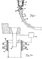
- a molten metal 2 is supplied to a casting mould 3 in the form of a box, open at the top and at the bottom, having cooled walls, usually of a copper-based alloy with a good thermal conductivity.
- the cooling in the casting mould causes the solidification of the elongated strand, formed by the molten metal, to begin from the outside and proceed inwards towards the centre of the strand.
- a strand is formed which is usually referred to as a slab.
- the cooled and partially solidified strand continuously leaves the casting mould.
- the strand leaves the casting mould, it has at least one mechanically self-supporting, solidified casing 4 that surrounds a non-solidified centre 5. It is shown schematically how it is sufficient with guide rollers S to guide and support the strand downstream of the casting mould.
- the primary flow 8 extends downwards in the casting direction, whereas the secondary flow 9 extends from the area of the walls 10 of the casting mould upwards towards the upper surface of the molten bath and then downwards.
- periodic velocity fluctuations arise in the cast material during the casting process. These fluctuations are also due to the walls of the casting mould being normally set into an oscillating movement to prevent solidified cast material from adhering thereto.
- the irregular movements caused thereby in the molten metal implies, inter alia, that bubbles, for example argon gas bubbles, and impurities in the melt, for example oxide inclusions from the casting pipe and slags from the meniscus, are transported far down in the casting direction, that is, far down in the cast strand that is initially formed in the casting mould. This results in inclusions and irregularities of the finished, solidified cast strand.
- bubbles for example argon gas bubbles
- impurities in the melt for example oxide inclusions from the casting pipe and slags from the meniscus
- a device as mentioned above is arranged to apply magnetic fields to the melt in the casting mould.
- EMBR ElectroMagnetic BRake
- a stationary magnetic field that is, a magnetic field generated by leading a direct current through a coil of an electromagnet, is applied to the melt in the casting mould from one long side to the other. This then results in the movements of the molten material being braked.
- such electromagnets may be arranged along the casting mould in the vicinity of, or below, the region for the supply of molten metal in order thus to brake the flow of the molten metal downwards in the casting mould, that is, substantially to influence the primary flow mentioned, to try to render the speed of this movement essentially constant over the whole cross section of the casting mould, and to stabilize the upwardly-directed secondary flow at the short sides of the casting mould.
- a so-called brake in the area of the upper surface of the casting mould to brake the movements of the molten metal in this area and remove surface oscillations in the melt.
- FC Flow Control
- EMS Electromagnetic Stirring
- the object of the present invention is to provide an apparatus and a method which make it possible to obtain, at least under certain casting conditions, a casting result which, at least in certain respects, is improved in relation to what is possible to achieve with prior art apparatuses and methods for continuous casting of metals.
- the device exhibits members adapted to generate a stationary magnetic field with a variable strength over essentially the whole of said cross-section of the casting mould from one long side to the other long side in the vicinity of, or below, the region for said supply of the molten metal, and members adapted to generate a variable magnetic field in the area of said upper surface in a region that is centrally located with respect to said cross section and close to said region for supply of melt, and, in addition, the apparatus exhibits a unit adapted to control the magnetic members of the device to generate, independently of each other, magnetic fields with an appearance that is dependent on the value prevailing of one or more predetermined casting parameters.
- a flow rate of the melt in various parts of the casting mould which is optimal for a uniform, stable temperature of the upper surface of the melt may to a large extent be achieved under changing casting conditions, primarily casting speed.
- variable magnetic field comprises also magnetic fields of so-called alternating type, that is, where the magnetic field is generated by an electromagnet supplied with an alternating current.
- alternating type that is, where the magnetic field is generated by an electromagnet supplied with an alternating current.
- a braking of the downward movement of the melt may be performed by means of the first-mentioned magnetic member, which permits the above-mentioned bubbles to rise to the upper surface and be removed and not be incorporated in the solidified portion of the strand, while at the same time the secondary flow upwards at the short ends of the strand may be stabilized for stable supply of hot melt to the meniscus and energy addition thereto.
- the last-mentioned magnetic member adapted to generate a variable magnetic field can ensure that the movements of the melt in the area of the upper surface thereof, especially in said central region, are the most suitable movements at a value prevailing of one or more of said predetermined casting parameters, for achieving, over the whole cross section of the casting mould, an essentially uniform speed of the melt at the upper surface and hence a uniform, stable temperature of the upper surface of the melt.
- the apparatus exhibits a device with members adapted to generate a stationary magnetic field with a variable strength in the area of said upper surface in the end regions of the casting mould which, with respect to said cross section, are located externally of and remotely from the above-mentioned region for supply of melt, and the apparatus further comprises a unit adapted to control said outer magnetic member to generate a magnetic field with a strength that is dependent on the value prevailing of one or more predetermined casting parameters.
- movements of the molten material in the area of said upper surface may be braked in said end regions to an extent that is optimal for the prevailing conditions on each individual casting occasion, that is, the value prevailing of one or more predetermined casting parameters.
- the apparatus according to the invention comprises both kinds of said magnetic members. This then leads to possibilities of achieving a flow rate of the melt in various parts of the casting mould which is optimal for the casting result, both deeper downwards in the casting mould and upwards in the casting mould, and in the area of the upper surface, as well as a uniform, stable temperature and movement of the upper surface of the melt irrespective of the casting speeds occurring.
- an excellent casting result may be obtained at low casting speeds, when the melt in the area of the upper surface needs to be stirred, above all near the casting pipe, and be accelerated, at casting speeds in an intermediate range, when hot molten material needs to be supplied to the area of the upper surface from the casting jet, stirring in the area of the upper surface around the casting pipe is needed and the movements of the melt in the area of the upper surface must be braked somewhat to obtain a maximum flow rate in the upper surface, and at high casting speeds, when the braking of the upper surface must be strong to achieve an optimum speed of the melt in the area of the upper surface, while at the same time no stagnation zones are allowed to arise centrally around the casting pipe.
- said magnetic members for generating a magnetic field in said central region comprise at least two magnetic cores, arranged at each long side of the casting mould, with electric conductor windings connected to different phases of a source for generating a polyphase ac voltage for achieving a magnetic field that travels in said central region in the upper surface of the melt in a direction towards the long side of the casting mould, which makes possible stirring and acceleration of the movement of the molten material in this central region of the upper surface of the melt when this is needed.
- the apparatus comprises means for varying the frequency of the current through the windings of the magnetic member for generating the magnetic field in said central region of the casting mould, and the unit is adapted to control said means in dependence on the value prevailing of one or more predetermined casting parameters.
- the molten material may in the central region be influenced into a movement which is the most optimal one for the particular casting conditions prevailing, and according to a further preferred embodiment of the invention, said means has the ability to control said frequency down to 0 Hz, which means that a direct current is then fed through the windings and a stationary magnetic field is generated in the area of the upper surface in said central region of the casting mould, such that these magnetic members then exert a braking effect on movements in this central region, which is suitable for high casting speeds.
- said strength of this braking effect is then controlled according to the casting speed and any other casting parameters so that an optimum movement of the molten material in this region occurs and no stagnation zones are formed in this area.
- said means is a converter of a kind known per se.
- the apparatus comprises members adapted to measure the temperature of the melt in the casting mould near said upper surface and to send information about this to the unit as a said predetermined casting parameter, members adapted to measure the casting speed, that is, how large a volume of melt that is supplied to the casting mould per unit of time, and to send information about this to the unit as a said predetermined casting parameter, and/or members adapted to measure the level of said upper surface of the melt in the casting mould and to send information about this to the unit as a said predetermined casting parameter. Since the unit takes into consideration different such casting parameters in its control of the magnetic members, in each given situation the molten material in the casting mould may be influenced to achieve an optimum casting result.
- the invention also includes the case where the unit is adapted to control one or more said magnetic members occasionally not to generate any magnetic field.
- any of the magnetic members could be completely shut off at a value of any casting parameter, such as casting speed, within a predetermined range of values.
- the unit is adapted, at determined values of one or more of said predetermined casting parameters, to control said members for generating a magnetic field in the area of the upper surface in said central region to alternately generate a so-called alternating field, changing in time, for stirring the molten metal and a stationary magnetic field for braking the movements of the molten metal.
- a very good temperature equalization of the melt in the area of the upper surface of the molten bath may be obtained.
- the unit is advantageously adapted to control said magnetic members in dependence on the value prevailing of one or more predetermined casting parameters according to an algorithm for the purpose of achieving a flow rate of the melt in different parts of the casting mould which is optimal for the casting result, and a uniform, stable temperature of the upper surface of the melt.
- the invention also relates to methods for continuous casting of metals according to the appended independent method claims. How these methods function and the advantages thereof should be manifestly clear from the above discussion of the apparatuses according to the invention.
- the invention also relates to a computer program, a computer program product and a computer-readable medium according to the corresponding appended claims. It is readily realized that the method according to the invention defined in the appended set of method claims is well suited to be carried out by program instructions from a processor controllable by a computer program provided with the program steps in question. Further advantages and advantageous features of the invention will be clear from the following description and the other dependent claims.
- the casting mould 3 has an elongated horizontal cross section, and in practice this normally means a considerably smaller relation of length of the short side to length of the long side than what is shown in the figures, and in this respect the figures are only to be interpreted as explaining the principles of the invention.
- the thickness of the strand may, for example, be of the order of magnitude of 150 mm while at the same time its width is over 1,500 mm.
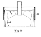
- the molten metal that is supplied to the casting mould has a certain overtemperature, that is, the temperature thereof must be lowered to a certain extent in order for any part thereof to start solidifying. This is important in order to avoid that solidification of the molten metal begins too early, for example in the area of its upper surface. To avoid such solidification, it is also necessary that the melt should exhibit a certain movement in all regions, cross section-wise both centrally and at the ends, such that an equalization of the temperature of the upper surface may occur. In Figure 3, it is shown how the melt typically flows in said secondary flow 9 in the upper surface.
- the primary flow 8 downwards of the melt be essentially constant over the whole horizontal cross section of the casting mould, so that bubbles and the like formed therein have a possibility of moving upwards to the upper surface 7 and disappearing and are not drawn along in some part that moves considerably faster than any other part.
- the apparatus exhibits magnetic members and a unit 12 adapted to control these members independently of each other in dependence on the value prevailing of one or more predetermined casting parameters.
- the magnetic members are schematically indicated electromagnets in the form of magnetic cores 13, preferably laminated iron cores, and electric conductor windings wound around these, which are schematically represented here.
- the unit 12 is adapted to control sources 15, 15', 15", connected to the different windings, for electrical energy to feed the windings with electric current and thereby generate magnetic fields extending from one long side to another in the casting mould through the melt.
- the apparatus thus exhibits first magnetic members 16 adapted to generate a stationary magnetic field with a variable strength across essentially the whole horizontal cross section of the casting mould from one long side to the other long side in the vicinity of, or below, the region for supply of the molten metal to the casting mould.
- the unit 12 controls the source 15" to feed the windings of the magnetic member 16 with direct current of a variable strength to generate a magnetic field that exerts a braking effect on the movement of the melt downwards in the casting mould and the upwardly-directed flow at the short sides of the casting mould.
- the apparatus also exhibits second magnetic members 17, also these being in the form of electromagnets, which are adapted to generate a variable magnetic field in the area of said upper surface in a region that is centrally located with respect to said cross section and close to said region for supply of melt.
- second magnetic members 17 also these being in the form of electromagnets, which are adapted to generate a variable magnetic field in the area of said upper surface in a region that is centrally located with respect to said cross section and close to said region for supply of melt.
- second magnetic members 17 also these being in the form of electromagnets, which are adapted to generate a variable magnetic field in the area of said upper surface in a region that is centrally located with respect to said cross section and close to said region for supply of melt.
- three coils are arranged, each being connected to a respective phase of a three-phase ac voltage.
- the apparatus exhibits schematically indicated means 18 adapted to convert the ac voltage from the current source 15' to set the frequency thereof, whereby the converter may preferably vary
- the apparatus exhibits third magnetic members 19, which are also of the electromagnet type and adapted to generate a stationary magnetic field with a variable strength in the area of said upper surface in those end regions of the casting mould which, with respect to said cross section, are located externally of and remotely from the region for supply of the melt. In this way, where necessary, the movements of the melt in the area of the upper surface may be braked in these end regions, but it is also possible to disconnect this magnetic member when no such braking is desired.
- the apparatus exhibits members for measuring certain parameters that are important for the casting and sending information about this to the unit 12, so that this unit can then control the different magnetic members in dependence on this information.
- a member 20 adapted to measure the temperature of the melt in the casting mould in an indirect manner by measuring the temperature of the wall of the casting mould.
- This temperature measurement may be performed continuously or intermittently at one or more points. It is then of special interest to measure the temperature in the area of the meniscus.
- the unit 12 preferably exhibits a processor capable of being influenced by a computer program for suitable control of the various magnetic members to achieve an optimum casting result.
- the second magnetic member 17 is preferably controlled to generate a travelling field with a relatively high strength to achieve such a stirring.
- the third magnetic members 19 could be almost or completely disconnected, whereas a certain degree of braking of the flows upwards and downwards in the molten metal through the first magnetic member 16 is desirable. In the upper surface this may result in the flow configuration according to Figure 3 with a controlled or uncontrolled flow A and a stirred flow B.
- the strength of the travelling field generated by the second magnetic member in the central region may be somewhat reduced, while at the same time the third magnetic members 19 are controlled to generate a stationary field that brakes the upper surface somewhat at the end regions.
- the second magnetic member 17 is advantageously controlled to generate a stationary, braking magnetic field in the central region of the upper surface, but the magnetic members 19 are controlled such that the braking effect is greater at the end regions to achieve a uniform speed of the molten material along the whole upper surface.
- the combination of the three magnetic members of the apparatus according to Figure 4 and the possibility of separate control thereof provided by the unit 12 contribute to achieve a flow rate of the melt in various parts of the casting mould which is optimal for the casting result, and to achieve a uniform, stable temperature of the upper surface of the melt at low and high casting speeds as well as casting speeds in the intermediate range.
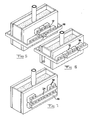
- FIG 5 illustrates schematically how an apparatus according to the invention could be provided with only first 16 and second 17 magnetic members, which makes this apparatus suited especially for lower casting speeds. It is pointed out that in this embodiment and the embodiments according to Figures 6 and 7, electromagnets are arranged along both long sides of the casting mould and these are supplied and controlled in a manner corresponding to that shown for the embodiment according to Figure 4, although this is not shown in these figures for reasons of simplification.
- Figure 6 illustrates an apparatus according to an embodiment that only exhibits said second 17 and third 19 magnetic members.
- the magnetic field generated by the third magnetic member 19 in an end region is closed by a yoke 23 interconnecting the electrodes
- Figure 7 shows the two electromagnets, belonging to the magnetic member 19 and arranged on the same long side, are arranged with their poles in such a way that the magnetic field is closed by a yoke 24 interconnecting these.
- the embodiment shown in Figure 7 with only first and third magnetic members 16 and 19, respectively, constitutes a simplified variant of the apparatus according to the invention, especially suited for higher casting speeds.
- the various magnetic members could have a different extent in the cross section of the casting mould to that shown in the figures, and, for example, in the embodiment according to Figure 5, the second magnetic member could extend a longer distance along the respective long side, possibly to the respective short side, depending on the casting process that is to be controlled.
- the number of phases could be different from three, for example two.
- the different magnetic fluxes could be closed in largely arbitrary ways.
- the magnetic flux from the magnetic members at the end regions of the upper surface could be closed via the first magnetic members located at a deeper level.
Claims (34)
- Gerät zum kontinuierlichen Gießen von Metallen umfassend:eine Gussform (3) mit einem langgestreckten horizontalen Querschnitt, durch den ein geschmolzenes Metall während des Gießprozesses hindurchgehen soll,ein Element (6) zum Zuführen von geschmolzenem Metall zu derart geschmolzenem Metall, das sich schon in der Gussform befindet, in einem Bereich in einem Abstand unterhalb der oberen Fläche der letzteren Schmelze, undeine Vorrichtung (13 - 19), die eingerichtet ist, Magnetfelder an die Schmelze in der Gussform anzulegen, um einen Einfluss auf die Bewegungen des geschmolzenen Metalls auszuüben, wobei die Vorrichtung Elemente (16) aufweist, die eingerichtet sind, um ein stationäres Magnetfeld mit einer veränderlichen Stärke über im Wesentlichen dem gesamten Querschnitt der Gussform von einer Längsseite zu der anderen Längsseite in der Nähe von, oder unterhalb des Bereichs für die Zuführung des geschmolzenen Metalls zu erzeugen, undElemente (17), die eingerichtet sind ein veränderliches Magnetfeld in dem Bereich der oberen Fläche in einem Bereich zu erzeugen, der in Bezug auf den Querschnitt zentral angeordnet ist, und nahe an dem Bereich zur Zuführung von Schmelze liegt,und dass das Gerät folgendes umfasst:eine Einheit (12), die eingerichtet ist, um die Magnetelemente der Vorrichtung zu steuern, um unabhängig voneinander Magnetfelder mit einer Erscheinung zu erzeugen, die von dem vorherrschenden Wert von einem oder mehreren vorher festgelegten Guss-Parameter abhängt,dadurch gekennzeichnet, dass
die Magnetelemente (16, 17) Magnetkerne (13) und elektrische Leiterwicklungen (14) umfassen, die um diese herumführen,
dass das Gerät eine oder mehrere Quellen (15, 15', 15") zur Zuführung von elektrischem Strom zu diesen Wicklungen umfasst, und dass die Einheit (12) eingerichtet ist, um die Zuführung von Strom zu den Wicklungen in Abhängigkeit von dem vorherrschenden Wert von einem oder mehreren vorher festgelegten Guss-Parameter zu steuern,
das magnetische Element (17) zum Erzeugen eines Magnetfeldes im Zentralbereich mindestens zwei Magnetkerne umfasst, die entlang jeder Längsseite der Gussform angeordnet sind, mit elektrischen Leiterwicklungen, die mit verschiedenen Phasen einer Quelle verbunden sind, zum Erzeugen einer Mehrphasen-Wechselspannung zum Erreichen eines Magnetfeldes, das sich in dem Zentralbereich in der oberen Fläche der Schmelze in Richtung der Längsseite der Gussform fortbewegt, und
das Gerät Mittel (18) zum Variieren der Frequenz des Stroms durch die Wicklungen des magnetischen Elements (17) zum Erzeugen des Magnetfeldes in dem Zentralbereich der Gussform umfasst, und die Einheit eingerichtet ist, dieses Mittel in Abhängigkeit von dem vorherrschenden Wert von einem oder mehreren vorher festgelegten Guss-Parametern zu steuern,
das Mittel (18) die Fähigkeit aufweist, die Frequenz hinunter bis zu 0 Hz zu steuern, so dass ein Gleichstrom durch die Wicklungen zugeführt wird und ein stationäres Magnetfeld in dem Bereich der oberen Fläche in dem Zentralbereich der Gussform erzeugt wird, und die Einheit eingerichtet ist, bei bestimmten Werten von einem oder mehreren der vorher festgelegten Guss-Parameter das Element (17) zum Erzeugen eines Magnetfeldes in dem Bereich der oberen Fläche in den Zentralbereichen zu steuern, um abwechselnd ein so genanntes Wechselfeld zu erzeugen, das sich mit der Zeit ändert, zum Rühren des geschmolzenen Metalls, und
ein stationäres Magnetfeld zum Bremsen der Bewegungen des geschmolzenen Metalls. - Gerät gemäß Anspruch 1, dadurch gekennzeichnet, dass die Vorrichtung des Weiteren Elemente (19) aufweist, die eingerichtet sind, um ein stationäres Magnetfeld mit veränderlicher Stärke in dem Bereich der oberen Fläche in den Endbereichen der Gussform zu erzeugen, die, in Bezug auf den Querschnitt, extern und entfernt von dem vorstehend erwähnten Bereich angeordnet sind, zum Zuführen der Schmelze,
dass das Gerät eine Einheit (12) umfasst, die eingerichtet ist, die äußeren Magnetelemente zu steuern, um ein Magnetfeld mit einer Stärke zu erzeugen, die von dem vorherrschenden Wert von einem oder mehreren vorher festgelegten Guss-Parametern abhängt, und
dass auch die Magnetelemente (19) zum Erzeugen eines Magnetfeldes in den Endbereichen Magnetkerne und elektrische Leiterwicklungen umfassen, die um diese herumführen, und
dass die Quellen eingerichtet sind, den Wicklungen elektrischen Strom zuzuführen, und
dass die Einheit (12) eingerichtet ist, die Zuführung von Strom zu den Wicklungen in Abhängigkeit von dem vorherrschenden Wert von einem oder mehreren vorher festgelegten Guss-Parametern zu steuern. - Gerät gemäß Anspruch 1 oder 2, dadurch gekennzeichnet, dass sich das Magnetelement (17) zum Erzeugen eines Magnetfeldes in dem Zentralbereich der oberen Fläche im Wesentlichen über den gesamten Querschnitt der Gussform von einer Schmalseite zu der anderen Schmalseite erstreckt, zum Erzeugen von Magnetfeldern in dem Bereich der oberen Fläche im Wesentlichen über den gesamten horizontalen Querschnitt.
- Gerät gemäß Anspruch 1 oder 2, dadurch gekennzeichnet, dass das Magnetelement (17) zum Erzeugen eines Magnetfeldes in dem Zentralbereich der Gussform mindestens drei Magnetkerne mit elektrischen Leiterwicklungen umfasst, und die eingerichtet sind um mit einer Drei-Phasen-Wechelspannung verbunden zu werden,
- Gerät gemäß Anspruch 1 oder 2, gekennzeichnet in 15, dass das Mittel (18) von einem Gleichstrom-Wechselstromwandler oder einem Wechselstrom-Gleichstromwandler gebildet wird.
- Gerät gemäß Anspruch 1 oder 2, dadurch gekennzeichnet, dass es Elemente (20) umfasst, die eingerichtet sind, um die Temperatur der Schmelze in der Gussform in der Nähe der oberen Fläche zu messen, und Informationen darüber als einen der vorher festgelegten Guss-Parameter an die Einheit zu senden.
- Gerät gemäß Anspruch 6, dadurch gekennzeichnet, dass das Temperatur-Mess-Element (20) eingerichtet ist, die Temperatur der Schmelze indirekt durch Erfassen der Temperatur einer Wand der Gussform zu messen.
- Gerät gemäß Anspruch 1 oder 2, dadurch gekennzeichnet, dass es Elemente (21) umfasst, die eingerichtet sind, die Gießgeschwindigkeit zu messen, d.h. wie groß ein Volumen der Schmelze ist, das der Gussform pro Zeiteinheit zugeführt wird, und Informationen darüber als einen der vorher festgelegten Guss-Parameter an die Einheit zu senden.
- Gerät gemäß Anspruch 1 oder 2, dadurch gekennzeichnet, dass es Elemente (22) umfasst, die eingerichtet sind, die Höhe der oberen Fläche der Schmelze in der Gussform zu messen, und Informationen darüber als einen der vorher festgelegten Guss-Parameter an die Einheit zu senden.
- Gerät gemäß Anspruch 1 oder 2, dadurch gekennzeichnet, dass die Einheit (12) eingerichtet ist, ein oder mehrere Magnetelemente zu steuern, um gelegentlich kein Magnetfeld zu erzeugen.
- Gerät gemäß Anspruch 10, dadurch gekennzeichnet, dass die Einheit (12) eingerichtet ist, unter ansonsten gleichen Bedingungen die Stärke des Magnetfeldes zu erhöhen, das von den Magnetelementen (16) in der Nähe von dem oder unterhalb des Bereichs zur Zufuhr des geschmolzenen Metalls erzeugt wird, bei gesteigerter Gießgeschwindigkeit und umgekehrt bei herabgesetzter Gießgeschwindigkeit.
- Gerät gemäß Anspruch 2, dadurch gekennzeichnet, dass die Einheit eingerichtet ist das Element (19) zum Erzeugen eines stationären Magnetfeldes in der oberen Fläche in den Endbereichen der Gussform zu steuern, um die Stärke des Magnetfeldes bei gesteigerter Gießgeschwindigkeit zu erhöhen und umgekehrt bei herabgesetzter Gießgeschwindigkeit.
- Gerät gemäß Anspruch 12, dadurch gekennzeichnet, dass die Einheit eingerichtet ist das Magnetelement (19) zum Erzeugen eines Magnetfeldes in den Endbereichen zu steuern, um bei einer Gießgeschwindigkeit unterhalb eines Schwellwerts kein Magnetfeld zu erzeugen.
- Gerät gemäß Anspruch 1, dadurch gekennzeichnet, dass die Einheit eingerichtet ist das Element (17) zum Erzeugen eines Magnetfeldes in dem Bereich der oberen Fläche in den Zentralbereichen zu steuern, um bei einer Gießgeschwindigkeit, die einen vorher festgelegten Schwellwert überschreitet, ein stationäres Magnetfeld zu erzeugen.
- Gerät gemäß Anspruch 1 oder 2, dadurch gekennzeichnet, dass die Einheit eingerichtet ist, die Magnetelemente (16, 17, 19) in Abhängigkeit von dem vorherrschenden Wert von einem oder mehreren vorher festgelegten Guss-Parameter gemäß eines Algorithmus zum Zweck des Erhaltens einer Flussrate der Schmelze in verschiedenen Teilen der Gussform, die für das Gießergebnis optimal ist, und einer gleichmäßigen, stabilen Temperatur der oberen Fläche der Schmelze zu steuern.
- Gerät gemäß Anspruch 1 oder 2, dadurch gekennzeichnet, dass die Zuführungselemente (6) eingerichtet sind, um das geschmolzene Metall in Form eines Strahls einem Bereich der Gussform zuzuführen, der im Wesentlichen zentral in Bezug auf den Querschnitt angeordnet ist.
- Verfahren zum kontinuierlichen Gießen von Metallen, wobei geschmolzenes Metall einer Gussform (3) mit einem langgestreckten horizontalen Querschnitt zugeführt wird zu derart geschmolzenem Metall, das sich schon in der Gussform befindet, in einem Bereich in einem Abstand unterhalb der oberen Fläche der letzteren Schmelze, wobei mindestens ein Magnetfeld an die Schmelze in der Gussform angelegt wird, um einen Einfluss auf die Bewegung des geschmolzenen Metalls auszuüben, wobei ein stationäres Magnetfeld mit einer veränderlichen Stärke im Wesentlichen über dem gesamten Querschnitt der Gussform von einer Längsseite zu der anderen Längsseite in der Nähe von dem oder unterhalb des Bereichs für die Zufuhr des geschmolzenen Metalls erzeugt wird, dass ein veränderliches Magnetfeld in dem Bereich der oberen Fläche in einem Bereich erzeugt wird, der in Bezug auf den Querschnitt zentral angeordnet ist und nahe dem Bereich für die Zufuhr von Schmelze, und dass die zwei Magnetfelder unabhängig voneinander erzeugt werden und so, dass jedes von ihnen eine Erscheinung aufweisen wird, die von dem vorherrschenden Wert von einem oder mehreren vorher festgelegten Guss-Parametern abhängt,
dadurch gekennzeichnet, dass
die Magnetfelder erzeugt werden, indem elektrischer Strom durch elektrische Leiterwicklungen (14) geschickt werden, die Magnetkerne (13) umgeben, und dass die Zufuhr von Strom zu den Wicklungen abhängig gemacht wird von dem vorherrschenden Wert von einem oder mehreren vorher festgelegten Guss-Parametern für die Steuerung der Magnetfelder, und
dass das Magnetfeld in dem Zentralbereich in Form eines Magnetfeldes erzeugt wird, das sich in dem Zentralbereich in dem Bereich der oberen Fläche der Schmelze in Richtung der Längsseite der Gussform fortbewegt, durch Zuführen, in einer Mehrphasen-Wechselstrom-Spannung, verschiedener Phasen zu den Wicklungen, die eine nach der anderen entlang der Längsseite der Gussform in horizontaler Richtung angeordnet sind, um das geschmolzene Material in dem Zentralbereich zu rühren, und
dass die Frequenz des Stroms durch die Wicklungen, die das Magnetfeld in dem Zentralbereich der Gussform erzeugen, in Abhängigkeit von dem vorherrschenden Wert von einem oder mehreren vorher festgelegten Guss-Parameter gesteuert wird, und bei bestimmten Werten von einem oder mehreren vorher festgelegten Guss-Parametern abwechselnd in dem Bereich der oberen Fläche in dem Zentralbereich ein so genanntes Wechselfeld erzeugt wird, das sich mit der Zeit ändert, um das geschmolzene Metall in diesem Bereich zu rühren, und ein stationäres Magnetfeld, um die Bewegungen des geschmolzenen Metalls in diesem Bereich zu bremsen. - Verfahren gemäß Anspruch 17, dadurch gekennzeichnet, dass zusätzlich ein stationäres Magnetfeld mit einer veränderlichen Stärke in dem Bereich der oberen Fläche in den Endbereichen der Gussform erzeugt wird, die bezüglich des Querschnitts extern und entfernt von dem vorstehend erwähnten Bereich zum Zuführen der Schmelze angeordnet sind,
dass die Stärke des Magnetfeldes in Abhängigkeit von dem vorherrschenden Wert von einem oder mehreren vorher festgelegten Guss-Parametern gesteuert wird, und
dass auch das stationäre Magnetfeld mit einer veränderlichen Stärke in den Endbereichen erzeugt wird, indem elektrischer Strom durch elektrische Leiterwicklungen geschickt wird, die Magnetkerne umgeben, und
dass die Zuführung von Strom zu den Wicklungen abhängig gemacht wird von dem vorherrschenden Wert von einem oder mehreren vorher festgelegten Guss-Parametem, zum Steuern des Magnetfeldes. - Verfahren gemäß den Ansprüchen 17 oder 18, dadurch gekennzeichnet, dass die Temperatur der Schmelze in der Gussform in der Nähe der oberen Fläche während des Gießprozesses gemessen wird und als einer der vorher festgelegten Guss-Parameter zur Steuerung des Magnetfeldes verwendet wird.
- Verfahren gemäß den Ansprüchen 17 - 18, dadurch gekennzeichnet, dass die Gießgeschwindigkeit d.h. wie groß ein Volumen der Schmelze ist, das der Gussform zugeführt pro Zeiteinheit wird, während des Gießprozesses gemessen wird und das Magnetfeld in Abhängigkeit der Größe dieser Gießgeschwindigkeit gesteuert wird.
- Verfahren gemäß den Ansprüchen 17 oder 18, dadurch gekennzeichnet, dass die Höhe der oberen Fläche der Schmelze in der Gussform während des Gießprozesses gemessen wird und das Magnetfeld in Abhängigkeit von dieser gemessenen Höhe gesteuert wird.
- Verfahren gemäß Anspruch 20, dadurch gekennzeichnet, dass unter ansonsten gleichen Bedingungen die Stärke des Magnetfeldes in der Nähe von, oder unterhalb des Bereichs zur Zufuhr des geschmolzenen Metalls bei gesteigerter Gießgeschwindigkeit erhöht wird, und umgekehrt bei herabgesetzter Gießgeschwindigkeit.
- Verfahren gemäß Anspruch 18, dadurch gekennzeichnet, dass die Stärke des stationären Magnetfeldes in dem Bereich der oberen Fläche in den Endbereichen der Gussform bei gesteigerter Gießgeschwindigkeit erhöht wird, und umgekehrt bei herabgesetzter Gießgeschwindigkeit.
- Verfahren gemäß Anspruch 23, dadurch gekennzeichnet, dass bei einer Gießgeschwindigkeit, die geringer ist als ein Schwellwert, ein Null-Magnetfeld, d.h. kein Magnetfeld in den Endbereichen der Gussform erzeugt wird.
- Verfahren gemäß Anspruch 17, dadurch gekennzeichnet, dass in dem Bereich der oberen Fläche in dem Zentralbereich ein stationäres Magnetfeld bei einer Gießgeschwindigkeit, die einen vorher festgelegten Schwellwert überschreitet, erzeugt wird.
- Verfahren gemäß Anspruch 17, dadurch gekennzeichnet, dass bei Gießgeschwindigkeiten, die in diesem Zusammenhang gering sind, unterhalb eines Schwellwerts für die Gießgeschwindigkeit, ein magnetisches Wechselfeld in dem Bereich der oberen Fläche in dem Zentralbereich erzeugt wird, um das geschmolzene Metall in diesem Bereich zu rühren.
- Verfahren gemäß den Ansprüchen 17 oder 18, dadurch gekennzeichnet, dass bei Gießgeschwindigkeiten in einem Zwischenbereich unterhalb eines unteren und eines oberen Schwellwerts in dem Bereich der oberen Fläche des Zentralbereichs ein magnetisches Wechselfeld erzeugt wird, um das geschmolzene Metall in diesem Bereich zu rühren, und ein stationäres Magnetfeld in dem Bereich der oberen Fläche in den Endbereichen, um die Bewegungen des geschmolzenen Metalls dort zu bremsen.
- Verfahren gemäß den Ansprüchen 17 oder 18, dadurch gekennzeichnet, dass bei hohen Gießgeschwindigkeiten oberhalb eines oberen Schwellwerts, wenn ein Bedarf einer starken Bremsung der Bewegungen des geschmolzenen Materials in dem Bereich der oberen Fläche besteht, ein stationäres Magnetfeld in dem Bereich der oberen Fläche in dem Zentralbereich erzeugt wird, um die Bewegungen des geschmolzenen Metalls dort zu bremsen, und ein stationäres Magnetfeld in dem Bereich der oberen Fläche in den Endbereichen erzeugt wird, um die Bewegungen des geschmolzenen Metalls dort zu bremsen.
- Verfahren gemäß den Ansprüchen 17 oder 18, dadurch gekennzeichnet, dass die Magnetfelder in Abhängigkeit von dem vorherrschenden Wert von einem oder mehreren vorher festgelegten Guss-Parametern gesteuert werden, gemäß eines Algorithmus zum Zweck des Erhaltens einer Flussrate der Schmelze in verschiedenen Teilen der Gussform, die für das Gießergebnis optimal ist, und einer gleichmäßigen, stabilen Temperatur der oberen Fläche der Schmelze.
- Verfahren gemäß den Ansprüchen 17 oder 18, dadurch gekennzeichnet, dass das geschmolzene Metall der Gussform zugeführt wird in Form eines Strahls in einem Bereich der Gussform, der in Bezug auf den Querschnitt im Wesentlichen zentral angeordnet ist.
- Computer-Programm zum Steuern eines Geräts zum kontinuierlichen Gießen von Metall, wobei das Computerprogramm Anweisungen zum Beeinflussen eines Prozessors umfasst, um eine Implementierung der Verfahrensschritte gemäß Anspruch 17 zu bewirken.
- Computer-Programm gemäß Anspruch 31, das mindestens teilweise über ein Netzwerk so wie das Internet bereitgestellt wird.
- Computer-Programm-Produkt, das direkt in den internen Speicher eines Digitalcomputers geladen werden kann und Softwarecodeabschnitte umfasst, um die Verfahrensschritte gemäß Anspruch 17 auszuführen, wenn das Produkt auf einem Computer ausgeführt wird.
- Computerlesbares Medium mit einem darauf registrierten Programm, das ausgelegt ist, um einen Computer dazu zu bringen, die Verfahrensschritte gemäß Anspruch 17 zu steuern.
Applications Claiming Priority (3)
| Application Number | Priority Date | Filing Date | Title |
|---|---|---|---|
| SE0103205A SE523881C2 (sv) | 2001-09-27 | 2001-09-27 | Anordning samt förfarande för kontinuerlig gjutning |
| SE0103205 | 2001-09-27 | ||
| PCT/SE2002/001756 WO2003041893A1 (en) | 2001-09-27 | 2002-09-27 | A device and a method for continuous casting |
Publications (2)
| Publication Number | Publication Date |
|---|---|
| EP1448329A1 EP1448329A1 (de) | 2004-08-25 |
| EP1448329B1 true EP1448329B1 (de) | 2007-03-21 |
Family
ID=20285453
Family Applications (1)
| Application Number | Title | Priority Date | Filing Date |
|---|---|---|---|
| EP02773100A Expired - Lifetime EP1448329B1 (de) | 2001-09-27 | 2002-09-27 | Stranggiessvorrichtung und -verfahren |
Country Status (10)
| Country | Link |
|---|---|
| US (2) | US6938674B2 (de) |
| EP (1) | EP1448329B1 (de) |
| JP (1) | JP4401777B2 (de) |
| KR (1) | KR100946612B1 (de) |
| CN (1) | CN1280041C (de) |
| AT (1) | ATE357300T1 (de) |
| DE (1) | DE60219062T2 (de) |
| ES (1) | ES2283602T3 (de) |
| SE (1) | SE523881C2 (de) |
| WO (1) | WO2003041893A1 (de) |
Families Citing this family (29)
| Publication number | Priority date | Publication date | Assignee | Title |
|---|---|---|---|---|
| AU2003283919A1 (en) | 2002-11-29 | 2004-06-23 | Abb Ab | Control system, computer program product, device and method |
| DE10350076A1 (de) * | 2003-10-27 | 2005-06-02 | Siemens Ag | Vorrichtung und Verfahren zum elektromagnetischen Rühren oder Bremsen von Metallguss, insbesondere Stahlstrangguss |
| KR101129500B1 (ko) * | 2004-11-09 | 2012-03-28 | 주식회사 포스코 | 전자기 제동 원리를 이용한 유동 제어 장치 및 그 방법 |
| FR2893868B1 (fr) * | 2005-11-28 | 2008-01-04 | Rotelec Sa | Reglage du mode de brassage electromagnetique sur la hauteur d'une lingotiere de coulee continue |
| PL2038081T3 (pl) * | 2006-07-06 | 2014-11-28 | Abb Ab | Sposób i urządzenie do sterowania przepływem stopionej stali w formie odlewniczej |
| CN101720262B (zh) * | 2007-06-06 | 2012-05-30 | 住友金属工业株式会社 | 钢的连续铸造方法及铸模内钢水的流动控制装置 |
| DE102009029889A1 (de) | 2008-07-15 | 2010-02-18 | Sms Siemag Ag | Elektromagnetische Bremseinrichtung an Stranggießkokillen |
| JP4505530B2 (ja) * | 2008-11-04 | 2010-07-21 | 新日本製鐵株式会社 | 鋼の連続鋳造用装置 |
| DE102010022691A1 (de) | 2010-06-04 | 2011-12-08 | Sms Siemag Ag | Stranggießvorrichtung mit einer Anordnung elektromagnetischer Spulen |
| IT1401311B1 (it) * | 2010-08-05 | 2013-07-18 | Danieli Off Mecc | Processo e apparato per il controllo dei flussi di metallo liquido in un cristallizzatore per colate continue di bramme sottili |
| JP5373728B2 (ja) * | 2010-09-17 | 2013-12-18 | 株式会社豊田中央研究所 | 自由鋳造方法、自由鋳造装置および鋳物 |
| ES2695045T3 (es) * | 2011-11-09 | 2018-12-28 | Nippon Steel & Sumitomo Metal Corporation | Aparato de colada continua para acero |
| BR112014014324B1 (pt) * | 2011-12-22 | 2018-07-03 | Abb Ab | Arranjo para um processo de fundição contínua e método para controle de fluxo de metal fundido em um vaso para um processo de fundição contínua |
| ITMI20120046A1 (it) * | 2012-01-18 | 2013-07-19 | Arvedi Steel Engineering S P A | Impianto e procedimento per la colata continua veloce di bramme sottili di acciaio e di bramme di acciaio |
| JP6087155B2 (ja) * | 2013-01-23 | 2017-03-01 | 株式会社神戸製鋼所 | チタンまたはチタン合金からなるスラブの連続鋳造方法 |
| GB201305822D0 (en) * | 2013-03-28 | 2013-05-15 | Pavlov Evgeny | Improvements in and relating to apparatus and methods |
| KR101526454B1 (ko) * | 2013-11-22 | 2015-06-05 | 주식회사 포스코 | 전자기 교반 장치 및 교반 방법 |
| US10207318B2 (en) | 2014-11-20 | 2019-02-19 | Abb Schweiz Ag | Electromagnetic brake system and method of controlling molten metal flow in a metal-making process |
| JP6930985B2 (ja) | 2016-01-27 | 2021-09-01 | ダブリュ.エル.ゴア アンド アソシエイツ,インコーポレイティドW.L. Gore & Associates, Incorporated | 絶縁構造 |
| GB201620027D0 (en) * | 2016-11-26 | 2017-01-11 | Altek Europe Ltd | Improvements in and relating to stirring molten metals in complex structures |
| CN108284208B (zh) * | 2017-01-09 | 2020-01-31 | 宝山钢铁股份有限公司 | 一种自适应拉速变化的电磁搅拌系统和搅拌方法 |
| CN108500228B (zh) * | 2017-02-27 | 2020-09-25 | 宝山钢铁股份有限公司 | 板坯连铸结晶器流场控制方法 |
| EP3415251A1 (de) * | 2017-06-16 | 2018-12-19 | ABB Schweiz AG | Elektromechanisches bremssystem und verfahren zur steuerung eines elektromechanischen bremssystems |
| CN112512679B (zh) | 2018-05-31 | 2023-04-21 | 斯攀气凝胶公司 | 火类增强的气凝胶组成物 |
| TW202003134A (zh) * | 2018-06-07 | 2020-01-16 | 日商日本製鐵股份有限公司 | 用於鋼之薄板鑄造的連續鑄造用設備及連續鑄造方法 |
| WO2020157020A1 (en) * | 2019-01-30 | 2020-08-06 | Abb Schweiz Ag | Flow speed control in continuous casting |
| US20220158534A1 (en) * | 2019-03-18 | 2022-05-19 | Primetals Technologies Austria GmbH | Electromagnetic brake for a mold of a slab contnuous casting assembly |
| KR102310701B1 (ko) * | 2019-12-27 | 2021-10-08 | 주식회사 포스코 | 주조 설비 및 주조 방법 |
| EP4249146A1 (de) * | 2022-03-21 | 2023-09-27 | Primetals Technologies Austria GmbH | Elektromagnetische rühr- und bremseinrichtung für eine kokille zur erzeugung von metallbrammen |
Family Cites Families (33)
| Publication number | Priority date | Publication date | Assignee | Title |
|---|---|---|---|---|
| US3817311A (en) * | 1972-10-13 | 1974-06-18 | Ibm | Method and apparatus for controlling a continuous casting machine |
| US4161206A (en) * | 1978-05-15 | 1979-07-17 | Olin Corporation | Electromagnetic casting apparatus and process |
| US4473104A (en) * | 1980-01-10 | 1984-09-25 | Olin Corporation | Electromagnetic casting process and apparatus |
| US4734869A (en) * | 1981-08-12 | 1988-03-29 | John Mickowski | Diagnostic method for analyzing and monitoring the process parameters in the operation of reciprocating equipment |
| JPS62203648A (ja) * | 1986-02-28 | 1987-09-08 | Nippon Steel Corp | 連続鋳造鋳型用電磁コイル装置 |
| US4744407A (en) * | 1986-10-20 | 1988-05-17 | Inductotherm Corp. | Apparatus and method for controlling the pour of molten metal into molds |
| JPS63104758A (ja) | 1986-10-22 | 1988-05-10 | Nkk Corp | 連続鋳造の湯面制御方法 |
| JPH07100223B2 (ja) * | 1987-01-30 | 1995-11-01 | 新日本製鐵株式会社 | 連続鋳造鋳型用電磁コイル装置 |
| US4955216A (en) * | 1988-01-29 | 1990-09-11 | Southwire Company | Method and apparatus for automatically adjusting soluble oil flow rates to control metallurgical properties of continuously rolled rod |
| JPH01271035A (ja) * | 1988-04-20 | 1989-10-30 | Nkk Corp | 鋼の連続鋳造方法 |
| US5027885A (en) * | 1988-05-16 | 1991-07-02 | Nippon-Steel Corporation | Injection apparatus and injection control method for high-speed thin plate continuous casting machine |
| US5242014A (en) * | 1988-11-30 | 1993-09-07 | Nippon Steel Corporation | Continuous casting method and apparatus for implementing same method |
| JPH037304A (ja) * | 1989-03-17 | 1991-01-14 | Olympus Optical Co Ltd | 歯科用遠心式鋳造装置 |
| US5197535A (en) * | 1991-09-17 | 1993-03-30 | J. Mulcahy Enterprises Inc. | Liquid metal stirring during casting |
| JPH05154620A (ja) * | 1991-12-04 | 1993-06-22 | Nippon Steel Corp | 連続鋳造方法 |
| JP2626861B2 (ja) * | 1992-08-28 | 1997-07-02 | 新日本製鐵株式会社 | 連続鋳造鋳型内溶鋼の流動制御装置 |
| JPH09262650A (ja) * | 1996-03-28 | 1997-10-07 | Nippon Steel Corp | 連続鋳造における鋳型内流動制御方法および装置 |
| KR100243636B1 (ko) * | 1996-05-14 | 2000-03-02 | 요시다 아키라 | 다이캐스팅기용 주조 제어 지원시스템 |
| JPH10305353A (ja) * | 1997-05-08 | 1998-11-17 | Nkk Corp | 鋼の連続鋳造方法 |
| SE523157C2 (sv) * | 1997-09-03 | 2004-03-30 | Abb Ab | Förfarande och anordning för att styra metallflödet vid stränggjutning medelst elektromagnetiska fält |
| US6082438A (en) * | 1997-10-08 | 2000-07-04 | Outboard Marine Corporation | Method and system for the control of a vacuum valve of a vacuum die casting machine |
| FR2772294B1 (fr) * | 1997-12-17 | 2000-03-03 | Rotelec Sa | Equipement de freinage electromagnetique d'un metal en fusion dans une installation de coulee continue |
| JPH11285795A (ja) * | 1998-03-31 | 1999-10-19 | Nippon Steel Corp | 清浄度の高い連続鋳造鋳片の製造方法 |
| JP3700396B2 (ja) * | 1998-06-16 | 2005-09-28 | Jfeスチール株式会社 | 鋼の連続鋳造装置 |
| EP1097013B1 (de) * | 1998-07-06 | 2002-09-18 | Disa Industries A/S | Verfahren und vorrichtung für den steigenden guss von metall |
| EP1121214A4 (de) * | 1998-07-24 | 2005-04-13 | Gibbs Die Casting Aluminum | Vorrichtung und verfahren zum giessen halbfester metalle |
| JP3671707B2 (ja) * | 1998-11-30 | 2005-07-13 | Jfeスチール株式会社 | 鋼の連続鋳造方法 |
| JP2000271711A (ja) * | 1999-03-26 | 2000-10-03 | Nippon Steel Corp | 導電性溶融物の流動制御装置 |
| EP1097765A4 (de) * | 1999-04-28 | 2005-02-09 | Sumitomo Metal Ind | Steuerung des schmelzlevels beim stranggiessen |
| JP2001219246A (ja) * | 2000-02-09 | 2001-08-14 | Nippon Steel Corp | 溶融金属の流動制御装置 |
| JP3663106B2 (ja) * | 2000-02-28 | 2005-06-22 | 東芝機械株式会社 | データ入出力装置 |
| US6796362B2 (en) * | 2000-06-01 | 2004-09-28 | Brunswick Corporation | Apparatus for producing a metallic slurry material for use in semi-solid forming of shaped parts |
| US6631752B2 (en) * | 2000-06-29 | 2003-10-14 | Diecast Software Inc. | Mathematically determined solidification for timing the injection of die castings |
-
2001
- 2001-09-27 SE SE0103205A patent/SE523881C2/sv unknown
-
2002
- 2002-09-27 KR KR1020047004556A patent/KR100946612B1/ko active IP Right Grant
- 2002-09-27 AT AT02773100T patent/ATE357300T1/de not_active IP Right Cessation
- 2002-09-27 WO PCT/SE2002/001756 patent/WO2003041893A1/en active IP Right Grant
- 2002-09-27 EP EP02773100A patent/EP1448329B1/de not_active Expired - Lifetime
- 2002-09-27 US US10/491,111 patent/US6938674B2/en not_active Expired - Lifetime
- 2002-09-27 CN CNB028235630A patent/CN1280041C/zh not_active Expired - Lifetime
- 2002-09-27 DE DE60219062T patent/DE60219062T2/de not_active Expired - Lifetime
- 2002-09-27 ES ES02773100T patent/ES2283602T3/es not_active Expired - Lifetime
- 2002-09-27 JP JP2003543767A patent/JP4401777B2/ja not_active Expired - Lifetime
-
2005
- 2005-07-29 US US11/192,367 patent/US7305271B2/en not_active Expired - Fee Related
Also Published As
| Publication number | Publication date |
|---|---|
| WO2003041893A1 (en) | 2003-05-22 |
| US20060054296A1 (en) | 2006-03-16 |
| SE523881C2 (sv) | 2004-05-25 |
| CN1596166A (zh) | 2005-03-16 |
| CN1280041C (zh) | 2006-10-18 |
| KR20040063121A (ko) | 2004-07-12 |
| JP4401777B2 (ja) | 2010-01-20 |
| US20050039876A1 (en) | 2005-02-24 |
| US6938674B2 (en) | 2005-09-06 |
| ES2283602T3 (es) | 2007-11-01 |
| SE0103205D0 (sv) | 2001-09-27 |
| US7305271B2 (en) | 2007-12-04 |
| ATE357300T1 (de) | 2007-04-15 |
| DE60219062T2 (de) | 2007-12-13 |
| EP1448329A1 (de) | 2004-08-25 |
| KR100946612B1 (ko) | 2010-03-09 |
| JP2005508755A (ja) | 2005-04-07 |
| DE60219062D1 (de) | 2007-05-03 |
| SE0103205L (sv) | 2003-03-28 |
Similar Documents
| Publication | Publication Date | Title |
|---|---|---|
| US7305271B2 (en) | Device and a method for continuous casting | |
| US7975753B2 (en) | Method and apparatus for controlling the flow of molten steel in a mould | |
| JP4824502B2 (ja) | 電磁場を用いる金属垂直連続鋳造方法とその実施のための鋳造設備 | |
| JP4591156B2 (ja) | 鋼の連続鋳造方法 | |
| JPH11514585A (ja) | 金属の鋳造方法および装置 | |
| KR100751021B1 (ko) | 연속적인 주조 주괴 주형에 용융 금속을 공급하는 장치 및그것을 사용하는 방법 | |
| JP5029324B2 (ja) | 鋼の連続鋳造方法 | |
| JP2005238276A (ja) | 電磁攪拌鋳造装置 | |
| JP2922363B2 (ja) | 連続鋳造鋳型内溶鋼の流動制御装置 | |
| WO1999011404A1 (en) | Method and device for continuous or semi-continuous casting of metal | |
| JPH0515949A (ja) | 金属の連続鋳造装置および鋳造方法 | |
| JPH05237621A (ja) | 連続鋳造方法 | |
| JP2607334B2 (ja) | 連続鋳造鋳型内溶鋼の流動制御装置 | |
| WO1999021670A1 (en) | Device for casting of metal | |
| US20120199308A1 (en) | Stirrer | |
| JP2607335B2 (ja) | 連続鋳造鋳型内溶鋼の流動制御装置 | |
| JP2633769B2 (ja) | 連続鋳造モールド内溶鋼流動制御方法 | |
| JPH06182497A (ja) | 金属の連続鋳造方法 | |
| WO1993004801A1 (en) | Method and apparatus for the electromagnetic stirring of molten metals in a wheel caster | |
| JPH0679418A (ja) | 電磁力を用いる鋼の連続鋳造方法 | |
| JPH08155590A (ja) | 複層鋳片の連続鋳造方法 | |
| JPH08155602A (ja) | 溶融金属の連続鋳造方法 |
Legal Events
| Date | Code | Title | Description |
|---|---|---|---|
| PUAI | Public reference made under article 153(3) epc to a published international application that has entered the european phase |
Free format text: ORIGINAL CODE: 0009012 |
|
| 17P | Request for examination filed |
Effective date: 20040423 |
|
| AK | Designated contracting states |
Kind code of ref document: A1 Designated state(s): AT BE BG CH CY CZ DE DK EE ES FI FR GB GR IE IT LI LU MC NL PT SE SK TR |
|
| AX | Request for extension of the european patent |
Extension state: AL LT LV MK RO SI |
|
| GRAP | Despatch of communication of intention to grant a patent |
Free format text: ORIGINAL CODE: EPIDOSNIGR1 |
|
| GRAS | Grant fee paid |
Free format text: ORIGINAL CODE: EPIDOSNIGR3 |
|
| GRAA | (expected) grant |
Free format text: ORIGINAL CODE: 0009210 |
|
| AK | Designated contracting states |
Kind code of ref document: B1 Designated state(s): AT BE BG CH CY CZ DE DK EE ES FI FR GB GR IE IT LI LU MC NL PT SE SK TR |
|
| PG25 | Lapsed in a contracting state [announced via postgrant information from national office to epo] |
Ref country code: AT Free format text: LAPSE BECAUSE OF FAILURE TO SUBMIT A TRANSLATION OF THE DESCRIPTION OR TO PAY THE FEE WITHIN THE PRESCRIBED TIME-LIMIT Effective date: 20070321 Ref country code: NL Free format text: LAPSE BECAUSE OF FAILURE TO SUBMIT A TRANSLATION OF THE DESCRIPTION OR TO PAY THE FEE WITHIN THE PRESCRIBED TIME-LIMIT Effective date: 20070321 Ref country code: CH Free format text: LAPSE BECAUSE OF FAILURE TO SUBMIT A TRANSLATION OF THE DESCRIPTION OR TO PAY THE FEE WITHIN THE PRESCRIBED TIME-LIMIT Effective date: 20070321 Ref country code: LI Free format text: LAPSE BECAUSE OF FAILURE TO SUBMIT A TRANSLATION OF THE DESCRIPTION OR TO PAY THE FEE WITHIN THE PRESCRIBED TIME-LIMIT Effective date: 20070321 Ref country code: BE Free format text: LAPSE BECAUSE OF FAILURE TO SUBMIT A TRANSLATION OF THE DESCRIPTION OR TO PAY THE FEE WITHIN THE PRESCRIBED TIME-LIMIT Effective date: 20070321 Ref country code: FI Free format text: LAPSE BECAUSE OF FAILURE TO SUBMIT A TRANSLATION OF THE DESCRIPTION OR TO PAY THE FEE WITHIN THE PRESCRIBED TIME-LIMIT Effective date: 20070321 |
|
| REG | Reference to a national code |
Ref country code: GB Ref legal event code: FG4D |
|
| REG | Reference to a national code |
Ref country code: CH Ref legal event code: EP |
|
| REF | Corresponds to: |
Ref document number: 60219062 Country of ref document: DE Date of ref document: 20070503 Kind code of ref document: P |
|
| REG | Reference to a national code |
Ref country code: IE Ref legal event code: FG4D |
|
| PG25 | Lapsed in a contracting state [announced via postgrant information from national office to epo] |
Ref country code: SE Free format text: LAPSE BECAUSE OF FAILURE TO SUBMIT A TRANSLATION OF THE DESCRIPTION OR TO PAY THE FEE WITHIN THE PRESCRIBED TIME-LIMIT Effective date: 20070621 |
|
| PG25 | Lapsed in a contracting state [announced via postgrant information from national office to epo] |
Ref country code: PT Free format text: LAPSE BECAUSE OF FAILURE TO SUBMIT A TRANSLATION OF THE DESCRIPTION OR TO PAY THE FEE WITHIN THE PRESCRIBED TIME-LIMIT Effective date: 20070821 |
|
| ET | Fr: translation filed | ||
| REG | Reference to a national code |
Ref country code: CH Ref legal event code: PL |
|
| NLV1 | Nl: lapsed or annulled due to failure to fulfill the requirements of art. 29p and 29m of the patents act | ||
| REG | Reference to a national code |
Ref country code: ES Ref legal event code: FG2A Ref document number: 2283602 Country of ref document: ES Kind code of ref document: T3 |
|
| PG25 | Lapsed in a contracting state [announced via postgrant information from national office to epo] |
Ref country code: SK Free format text: LAPSE BECAUSE OF FAILURE TO SUBMIT A TRANSLATION OF THE DESCRIPTION OR TO PAY THE FEE WITHIN THE PRESCRIBED TIME-LIMIT Effective date: 20070321 |
|
| PG25 | Lapsed in a contracting state [announced via postgrant information from national office to epo] |
Ref country code: CZ Free format text: LAPSE BECAUSE OF FAILURE TO SUBMIT A TRANSLATION OF THE DESCRIPTION OR TO PAY THE FEE WITHIN THE PRESCRIBED TIME-LIMIT Effective date: 20070321 |
|
| PLBE | No opposition filed within time limit |
Free format text: ORIGINAL CODE: 0009261 |
|
| STAA | Information on the status of an ep patent application or granted ep patent |
Free format text: STATUS: NO OPPOSITION FILED WITHIN TIME LIMIT |
|
| PG25 | Lapsed in a contracting state [announced via postgrant information from national office to epo] |
Ref country code: DK Free format text: LAPSE BECAUSE OF FAILURE TO SUBMIT A TRANSLATION OF THE DESCRIPTION OR TO PAY THE FEE WITHIN THE PRESCRIBED TIME-LIMIT Effective date: 20070321 |
|
| 26N | No opposition filed |
Effective date: 20071227 |
|
| PG25 | Lapsed in a contracting state [announced via postgrant information from national office to epo] |
Ref country code: GR Free format text: LAPSE BECAUSE OF FAILURE TO SUBMIT A TRANSLATION OF THE DESCRIPTION OR TO PAY THE FEE WITHIN THE PRESCRIBED TIME-LIMIT Effective date: 20070622 Ref country code: MC Free format text: LAPSE BECAUSE OF NON-PAYMENT OF DUE FEES Effective date: 20070930 |
|
| PG25 | Lapsed in a contracting state [announced via postgrant information from national office to epo] |
Ref country code: IE Free format text: LAPSE BECAUSE OF NON-PAYMENT OF DUE FEES Effective date: 20070927 |
|
| PG25 | Lapsed in a contracting state [announced via postgrant information from national office to epo] |
Ref country code: EE Free format text: LAPSE BECAUSE OF FAILURE TO SUBMIT A TRANSLATION OF THE DESCRIPTION OR TO PAY THE FEE WITHIN THE PRESCRIBED TIME-LIMIT Effective date: 20070321 |
|
| PG25 | Lapsed in a contracting state [announced via postgrant information from national office to epo] |
Ref country code: CY Free format text: LAPSE BECAUSE OF FAILURE TO SUBMIT A TRANSLATION OF THE DESCRIPTION OR TO PAY THE FEE WITHIN THE PRESCRIBED TIME-LIMIT Effective date: 20070321 |
|
| PG25 | Lapsed in a contracting state [announced via postgrant information from national office to epo] |
Ref country code: BG Free format text: LAPSE BECAUSE OF FAILURE TO SUBMIT A TRANSLATION OF THE DESCRIPTION OR TO PAY THE FEE WITHIN THE PRESCRIBED TIME-LIMIT Effective date: 20070621 Ref country code: LU Free format text: LAPSE BECAUSE OF NON-PAYMENT OF DUE FEES Effective date: 20070927 |
|
| PG25 | Lapsed in a contracting state [announced via postgrant information from national office to epo] |
Ref country code: TR Free format text: LAPSE BECAUSE OF FAILURE TO SUBMIT A TRANSLATION OF THE DESCRIPTION OR TO PAY THE FEE WITHIN THE PRESCRIBED TIME-LIMIT Effective date: 20070321 |
|
| REG | Reference to a national code |
Ref country code: FR Ref legal event code: PLFP Year of fee payment: 15 |
|
| REG | Reference to a national code |
Ref country code: FR Ref legal event code: PLFP Year of fee payment: 16 |
|
| REG | Reference to a national code |
Ref country code: GB Ref legal event code: 732E Free format text: REGISTERED BETWEEN 20180327 AND 20180328 |
|
| REG | Reference to a national code |
Ref country code: DE Ref legal event code: R082 Ref document number: 60219062 Country of ref document: DE Representative=s name: BECKER-KURIG-STRAUS PATENTANWAELTE PARTNERSCHA, DE Ref country code: DE Ref legal event code: R082 Ref document number: 60219062 Country of ref document: DE Representative=s name: BECKER & KURIG PARTNERSCHAFT PATENTANWAELTE MB, DE Ref country code: DE Ref legal event code: R082 Ref document number: 60219062 Country of ref document: DE Representative=s name: BECKER & KURIG PARTNERSCHAFT PATENTANWAELTE PA, DE Ref country code: DE Ref legal event code: R082 Ref document number: 60219062 Country of ref document: DE Representative=s name: BECKER, KURIG, STRAUS, DE Ref country code: DE Ref legal event code: R081 Ref document number: 60219062 Country of ref document: DE Owner name: ABB SCHWEIZ AG, CH Free format text: FORMER OWNER: ABB AB, VAESTERAS, SE |
|
| REG | Reference to a national code |
Ref country code: ES Ref legal event code: PC2A Owner name: ABB SCHWEIZ AG. Effective date: 20180522 Ref country code: ES Ref legal event code: PC2A Effective date: 20180522 |
|
| REG | Reference to a national code |
Ref country code: FR Ref legal event code: PLFP Year of fee payment: 17 |
|
| REG | Reference to a national code |
Ref country code: FR Ref legal event code: TP Owner name: ABB SCHWEIZ AG, CH Effective date: 20181106 |
|
| PGFP | Annual fee paid to national office [announced via postgrant information from national office to epo] |
Ref country code: IT Payment date: 20210922 Year of fee payment: 20 Ref country code: FR Payment date: 20210921 Year of fee payment: 20 |
|
| PGFP | Annual fee paid to national office [announced via postgrant information from national office to epo] |
Ref country code: DE Payment date: 20210920 Year of fee payment: 20 Ref country code: GB Payment date: 20210920 Year of fee payment: 20 |
|
| PGFP | Annual fee paid to national office [announced via postgrant information from national office to epo] |
Ref country code: ES Payment date: 20211119 Year of fee payment: 20 |
|
| REG | Reference to a national code |
Ref country code: DE Ref legal event code: R071 Ref document number: 60219062 Country of ref document: DE |
|
| REG | Reference to a national code |
Ref country code: ES Ref legal event code: FD2A Effective date: 20221004 |
|
| REG | Reference to a national code |
Ref country code: GB Ref legal event code: PE20 Expiry date: 20220926 |
|
| PG25 | Lapsed in a contracting state [announced via postgrant information from national office to epo] |
Ref country code: GB Free format text: LAPSE BECAUSE OF EXPIRATION OF PROTECTION Effective date: 20220926 Ref country code: ES Free format text: LAPSE BECAUSE OF EXPIRATION OF PROTECTION Effective date: 20220928 |