EP1446855B1 - Procede et dispositif d'alimentation en energie electrique d'un appareil - Google Patents
Procede et dispositif d'alimentation en energie electrique d'un appareil Download PDFInfo
- Publication number
- EP1446855B1 EP1446855B1 EP02793218.5A EP02793218A EP1446855B1 EP 1446855 B1 EP1446855 B1 EP 1446855B1 EP 02793218 A EP02793218 A EP 02793218A EP 1446855 B1 EP1446855 B1 EP 1446855B1
- Authority
- EP
- European Patent Office
- Prior art keywords
- battery
- circuit
- voltage
- storage means
- power supply
- Prior art date
- Legal status (The legal status is an assumption and is not a legal conclusion. Google has not performed a legal analysis and makes no representation as to the accuracy of the status listed.)
- Expired - Lifetime
Links
Images

Classifications
-
- H—ELECTRICITY
- H02—GENERATION; CONVERSION OR DISTRIBUTION OF ELECTRIC POWER
- H02J—ELECTRIC POWER NETWORKS; CIRCUIT ARRANGEMENTS OR SYSTEMS FOR SUPPLYING OR DISTRIBUTING ELECTRIC POWER; SYSTEMS FOR STORING ELECTRIC ENERGY
- H02J7/00—Circuit arrangements for charging or discharging batteries or for supplying loads from batteries
- H02J7/34—Parallel operation in networks using both storage and other DC sources, e.g. providing buffering
- H02J7/342—The other DC source being a battery actively interacting with the first one, i.e. battery to battery charging
-
- H—ELECTRICITY
- H02—GENERATION; CONVERSION OR DISTRIBUTION OF ELECTRIC POWER
- H02J—ELECTRIC POWER NETWORKS; CIRCUIT ARRANGEMENTS OR SYSTEMS FOR SUPPLYING OR DISTRIBUTING ELECTRIC POWER; SYSTEMS FOR STORING ELECTRIC ENERGY
- H02J7/00—Circuit arrangements for charging or discharging batteries or for supplying loads from batteries
- H02J7/865—Battery or charger load switching, e.g. concurrent charging and load supply
-
- H—ELECTRICITY
- H02—GENERATION; CONVERSION OR DISTRIBUTION OF ELECTRIC POWER
- H02M—APPARATUS FOR CONVERSION BETWEEN AC AND AC, BETWEEN AC AND DC, OR BETWEEN DC AND DC, AND FOR USE WITH MAINS OR SIMILAR POWER SUPPLY SYSTEMS; CONVERSION OF DC OR AC INPUT POWER INTO SURGE OUTPUT POWER; CONTROL OR REGULATION THEREOF
- H02M1/00—Details of apparatus for conversion
- H02M1/10—Arrangements incorporating converting means for enabling loads to be operated at will from different kinds of power supplies, e.g. from AC or DC
-
- H—ELECTRICITY
- H02—GENERATION; CONVERSION OR DISTRIBUTION OF ELECTRIC POWER
- H02J—ELECTRIC POWER NETWORKS; CIRCUIT ARRANGEMENTS OR SYSTEMS FOR SUPPLYING OR DISTRIBUTING ELECTRIC POWER; SYSTEMS FOR STORING ELECTRIC ENERGY
- H02J2207/00—Details of circuit arrangements for charging or discharging batteries or supplying loads from batteries
- H02J2207/20—Charging or discharging characterised by the power electronics converter
-
- H—ELECTRICITY
- H02—GENERATION; CONVERSION OR DISTRIBUTION OF ELECTRIC POWER
- H02J—ELECTRIC POWER NETWORKS; CIRCUIT ARRANGEMENTS OR SYSTEMS FOR SUPPLYING OR DISTRIBUTING ELECTRIC POWER; SYSTEMS FOR STORING ELECTRIC ENERGY
- H02J2207/00—Details of circuit arrangements for charging or discharging batteries or supplying loads from batteries
- H02J2207/40—Details of circuit arrangements for charging or discharging batteries or supplying loads from batteries adapted for charging from various sources, e.g. AC, DC or multivoltage
Definitions
- the present invention relates to a portable power supply device, in particular for powering a device such as a mobile phone.
- the document WO97 / 08804 shows a portable power supply device comprising connection means for connecting an appliance comprising at least one battery pack, a supply circuit supplying a supply voltage, a rechargeable electrical energy storage means , the circuit charging the energy storage means when the circuit is connected to a suitable power source, the connecting means for powering the apparatus and / or charging the power supply battery of the apparatus to from the energy storage means.
- connection means for connecting an appliance comprising at least one battery pack, a supply circuit supplying a supply voltage, a rechargeable electrical energy storage means , the circuit charging the energy storage means when the circuit is connected to a suitable power source, the connecting means for powering the apparatus and / or charging the power supply battery of the apparatus to from the energy storage means.
- a major disadvantage stems from the fact that the autonomy of these devices is limited by the energy storage capacity of their battery, which requires recharging them regularly using a charger from the power supply. The problem becomes critical when the user does not have access to the area. Similarly, the user sometimes has access to the sector for a short time, for example half an hour or less. However, charging the batteries of these devices very often require at least an hour, or even three hours, if not more. As a result, the battery of the device will only be partially recharged.
- the invention aims to at least partially overcome the disadvantages of the prior art.
- a first object of the invention is to facilitate the supply or charging of an electrical appliance in the presence of different electrical energy sources.
- Another object of the invention is to extend the autonomy of electrical appliances incorporating a rechargeable battery pack.
- Yet another object of the invention is to provide a satisfactory autonomy to such devices despite limited availability of mains power or other times.
- low voltage means a voltage less than or equal to preferably 60 volts, more preferably 40 volts or 28 volts.
- the device is preferably designed to accept as input any low voltage in a range for example from 3 to 60 volts. Alternatively, it may be provided for one or more pre-defined low voltages such as 6 volts, 12 volts and 24 volts.
- the battery may be charged by the device whether the battery is in the device or the battery has been previously removed from the device for the charging operation.
- the circuit comprises a voltage converter outputting a given voltage used to power the apparatus, when the circuit is connected to a low-voltage electrical energy source. But if the circuit is connected to a low-voltage electrical power source having a voltage within a predetermined voltage range including the voltage output of the converter, then the circuit supplies the device connected to the connection means from the source of electrical energy without the intermediary of the converter.
- the device provides power to the device through the storage means loaded at least partially, even if the charger circuit is no longer connected to the source of electrical energy for charging.
- the capacity of the storage means is chosen to be able to feed the apparatus preferably for at least half an hour, but more advantageously for at least one hour, see two hours.
- the capacity of the storage means is at least equal to the storage capacity of the battery of the device, or at least half of the latter .
- the circuit can super-fast charge the energy storage means when the circuit is connected to a suitable power source.
- the ultrafast charge of the storage means corresponds to the electrical charge of the storage means to at least 50% of its storage capacity carried out in less than half an hour, preferably in less than a quarter of an hour and more advantageously in less than 8 minutes.
- the device thus allows rapid refills of its storage means even when the power source is available for a few minutes such as for example a businessman passing through his hotel room for a few minutes between two appointments outside.
- the device allows to feed the device thereafter in the absence of any other source of energy. Since it is portable, the user can take the device with him to power his device in any place.
- This embodiment is all the more advantageous when the battery pack of the device and / or the device itself are not designed to allow ultra-fast charging of this battery.
- the storage means provides a significant autonomy compared to the battery pack of the device, when the charging time is limited by the circumstances.
- devices incorporating a battery pack - such as phones or laptops - do not allow ultra-fast charging of the battery.
- neither the circuits of the device nor the battery itself can withstand the high currents - usually several amperes - required for such an ultrafast load. These devices usually require at least an hour, and often at least three hours, if not more, to recharge their battery.
- the electrical energy storage means may comprise a rechargeable battery.
- the capacity of the rechargeable battery is less than or equal to preferably three times, more preferably twice, or even once and half the storage capacity of the battery of the device, which allows compactness and a limited weight of the device thus improving its portability.
- the electrical energy storage means comprises a rechargeable battery and the latter comprises several accumulator cells connected in series when the battery supplies the connected device to the connection means, each cell of the battery being charged with ultrafast way through a respective load control circuit.
- the circuit comprises a voltage converter supplying at output a given voltage used for charging - possibly ultrafast - energy storage means, when the circuit is connected to a source of low electrical energy voltage, and the energy storage means supplies the device connected to the connection means through the converter operating voltage booster when the voltage across the energy storage means is below a predetermined threshold.
- the circuit when the circuit is connected to a low-voltage electrical power source having a voltage within a predetermined voltage range including the voltage outputted from the converter, the circuit supplies power to the connected device. connecting means, and / or loads the energy storage means, from the source of electrical energy without the intermediary of the converter.
- the circuit comprises a voltage converter outputting a given voltage for charging the energy storage means and / or supplying the device connected to the connection means, when the circuit is connected to a low voltage power source. But when the circuit is connected to a low-voltage electrical power source having a voltage within a predetermined voltage range including the voltage output of the converter, then the circuit supplies the device connected to the connection means and / or charges the energy storage means, from the source of electrical energy without the intermediary of the converter.
- the circuit when the circuit is connected to a source of electrical energy having a voltage below a predetermined threshold, the circuit supplies the device connected to the connection means, but does not charge the energy storage means.
- the device may advantageously comprise a circuit limiting the current supplied to the device.
- the device may further include a solar panel for powering the apparatus and / or charging the energy storage means.
- the device comprises connection means for connecting a removable and portable electrical energy storage means in which, when said removable electrical energy storage means is connected to said connection means, the The power supply circuit charges the detachable energy storage means rapidly when the supply circuit is connected to a suitable power source.
- the device may or may not include another non-removable storage means as described above.
- the removable energy storage means may include a rechargeable battery. The removable storage means thus charged can be disconnected from the device and can then power a device - for example to recharge the battery of the device if it has - in the absence of any other source of energy. Since it is portable, the user can take the removable storage means with him to power his device in any place.
- the preferred indications concerning the choice of the capacity of the energy storage means of the device given above also apply to the means of removable storage.
- the invention also proposes the use of the device of the invention for powering an electrical appliance.
- the device is preferably portable type, preferably a mobile phone or a laptop or a pocket diary.
- An advantageous use lies in the fact that the device of the invention recharges a battery pack (2) of the electrical apparatus.
- the load of an energy storage means of the invention can be implemented independently of the fact that the device of the invention can be optionally connected to a mains power supply and to a source of low voltage electrical energy.
- the invention makes it possible to recharge the storage means in situations where the source of electric power is available for a short time, for example, a businessman passing through his hotel room for a few minutes between two appointments. outside.
- the storage means thus charged then allows to power its device in the absence of any other source of energy. Since it is portable, the user can take the storage means with him to power his device in any place.
- the invention is particularly suitable for the supply of apparatus having a low voltage supply input, for example 6 volts, 9 volts or 12 volts.
- the invention is all the more advantageous when the battery pack of the device and / or the device itself are not designed to allow ultra-fast charging of this battery.
- the storage means provides a significant autonomy compared to the battery pack of the device, when the charging time is limited by the circumstances.
- devices incorporating a battery pack - such as phones or laptops - do not allow ultra-fast charging of the battery.
- neither the circuits of the device nor the battery itself can withstand the high currents - usually several amperes - required for such an ultrafast load. These devices usually require at least an hour, and often at least three hours, if not more, to recharge their battery.
- the energy storage means can be used to recharge the power supply battery. the device.
- the capacity of the storage means is at least equal to the storage capacity of the battery of the device, or at least half of the latter.
- the storage means then reloads significantly the battery of the device.
- the capacity of the storage means especially if it comprises a rechargeable battery, is less than or equal to preferably three times, more advantageously twice or even one and a half times the storage capacity of the battery of the battery. the device, which allows a compactness and a limited weight thus improving its portability.
- This embodiment of the invention is again particularly advantageous when the battery pack of the device and / or the device itself are not designed to allow ultra-fast charging of its battery.
- This embodiment allows charging of the storage means even if the source of electrical energy - for example the sector or a cigarette lighter socket of a car - is available only a few minutes. Because it is portable, the user can take the storage means with him to recharge the battery of his device thanks to it while he no longer has access to the source of electrical energy. .
- the energy storage means is connected to the power input of the apparatus via a circuit limiting the current supplied. the apparatus.
- This limiter circuit protects the device against overcurrents that could damage it.
- step a) the charging of the energy storage means is carried out using a charger intended to be connected optionally to a mains power supply or to a power supply.
- source of low voltage electrical energy As already indicated, in the context of the invention, low voltage means a voltage less than or equal to 60 volts.
- step a) the charging of the energy storage means is carried out using a charger also provided for powering the apparatus. It is thus possible to simultaneously charge the storage means and to power the device, as well as to charge the battery of the latter if necessary.
- the device to be powered is preferably of the portable type. It can be advantageously a mobile phone or a laptop or a pocket diary.
- the device according to the invention makes it possible to supply the device with the at least partially charged storage means, even if the charger circuit is no longer connected to the source of electrical energy used to charge it.
- the capacity of the storage means is chosen to be able to feed the apparatus preferably for at least half an hour, but more advantageously for at least one hour, see two hours.
- this device allows rapid refills of its storage means even when the power source is available for a few minutes, the device for powering the device by the in the absence of any other source of energy.
- the electrical energy storage means comprises a rechargeable battery.
- the battery may comprise a plurality of accumulator cells connected in series when the battery supplies the device connected to the connection means and each cell may advantageously be charged in a very fast manner through a respective charge control circuit.
- the charger circuit supplies the device connected to the connection means, when the charger circuit is connected to the source of electrical energy.
- the charger circuit is suitable for connection to a mains power supply or to a low voltage supply.
- the charger circuit comprises a voltage converter outputting a given voltage for the ultra-fast charging of the energy storage means, when the device is connected to a power source. electrical low voltage, and in that the energy storage means supplies the device connected to the connection means through the converter operating voltage booster when the voltage across the energy storage means is less than a predetermined threshold.
- the charger circuit when the charger circuit is connected to a low-voltage electrical power source having a voltage within a predetermined voltage range including the voltage output of the converter, the charger circuit supplies the device connected to the connection means, and / or loads the energy storage means, from the source of electrical energy without the intermediary of the converter.
- the charger circuit when the charger circuit is connected to a source of electrical energy having a voltage lower than a predetermined threshold, the charger circuit supplies the device connected to the connection means, but does not charge the storage means. energy.
- the circuit when the circuit is connected to a source of electrical energy having a voltage greater than or equal to said predetermined threshold, the circuit supplies the device connected to the connection means and charges the energy storage means.
- the invention has the advantage of not requiring modifications of the electrical appliances to be powered, in particular the physical connection interface serving as the power input of the devices. Therefore, the invention can be implemented for any existing electrical device.
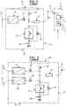
- the feeding of the embodiment of the figure 1 is not intended to be connected to a low voltage source, but only to a mains supply.
- the presentation first makes it possible to understand the other aspects of the invention before describing with reference to the figure 1 the embodiments of the other figures which include a possibility of connection to a low voltage source.
- the power supply 5 illustrated at figure 1 is intended to be used with a mobile phone 1.
- the mobile phone 1 can be of any known type. Classically, it is powered by a rechargeable battery 2 which is housed in its housing.
- the housing of the telephone 1 is generally provided with a connector 3 for recharging the battery 2 through a control circuit 4.
- the control circuit 4 serves in particular to check the charge level of the battery 2 to inform the user as well as the need or not to recharge the battery 2 and / or protect the battery 2 against misuse.
- Charging the battery 2 is performed by applying to the connector 3 a voltage of about 5 VDC which is provided in this case by the power supply 5 according to the invention.
- the power supply 5 comprises a converter circuit 6 which outputs a DC voltage of 6 volts from the sector applied to its input.
- the converter 6 can be of any suitable conventional type. In particular, it may be a conventional power supply circuit based on a transformer, a Graetz bridge and a filter capacitor. Nevertheless, it is preferable to use a switching power supply which has the advantage of being more compact and light.
- the converter 6 is preferably designed to accept as input the AC voltages of the existing power supplies in the different countries, in particular 110 volts 60 Hz and 220 to 240 volts, 50 Hz.
- the converter 6 can be implemented in the form of a switched-mode power supply automatically adapting as input to an entire range of AC or DC voltages covering the different mains supply voltages existing in the world.
- the converter 6 may be provided to receive as input any voltage in the range of 80 to 240 volts AC - 50 or 60 Hz - or in a range of 100 to 350 volts DC.
- the input of the converter 6 can be conventionally connected to the mains by means of a cord 7 provided at its end with a plug.
- the power supply 5 comprises a rechargeable battery 10.
- the output of the converter 6 is connected to the battery 10 to recharge it when the power supply 5 is connected to the mains.
- the converter 6 is preferably provided to carry out an ultrafast charge of the battery 10.
- the battery 10 is therefore chosen to tolerate such an ultrafast load and the converter 6 is designed to deliver a current sufficient to allow this charge.
- Such batteries particularly of the nickel-cadmium type in sealed cylindrical form, are for example marketed by the French company Saft.
- a circuit 11 controls the charging current applied to the battery 10.
- the control circuit 11 has been represented symbolically in the form of a controlled switch. In practice, this control circuit 11 can be implemented in a known manner, in particular by following the instructions of the battery manufacturer. It may in particular be based on a MOS transistor used in switching.
- the ultra-fast charge is to apply a constant high current until the voltage across the battery - or each of its cells - reaches a predefined threshold, which generally allows the battery to be recharged at about 75% of the battery. his ability, see more. The charge can then be continued slower at lower currents. Generally, it is It is also desirable to monitor the charging current of the battery according to the temperature of the battery. This role can also be provided by the circuit 11.
- the battery 10 is connected to a cord 8 provided at its end with a connector for connecting the power supply 5 to the connector 3 of the mobile telephone 1.
- the load control circuit 11 can be bridged by a diode 12.
- the diode 12 is preferably a Shottky diode because of the low voltage drop present at its terminals when it is conducting.
- the battery 10 thus makes it possible to recharge the battery of the telephone 1 and / or to directly feed the telephone 1.
- the control circuit 11 is based on a bidirectional switch, the role of the diode 12 can also be assumed by the switch of the control circuit 11 in which case the diode 12 is superfluous.
- the power supply 5 preferably comprises a circuit 9 limiting the current supplied by the battery 10 to the telephone 1.
- the current limiting circuit 9 serves to protect the mobile phone 1 against overcurrents that could damage it - this is especially the case when charging of the battery 2 by the power supply 5 - because the control circuit 4 of the telephone 1 does not generally provide this function or insufficiently.
- the current limiting circuit 9 may consist of a simple resistor. But it can also be a controlled switch - such as a MOS transistor - chopping the current as a function of the evolution of the charging current supplied to the battery 2.
- the choice of the battery 10 with regard to its storage capacity is made in consideration of the energy consumption of the device to be powered, in this case, in consideration of the capacity of the telephone battery 1.
- the a storage capacity of the battery 10 sufficient to completely charge the battery 2 or at least 90% is chosen.
- the storage capacity is preferably chosen at least equal to that of the battery 2.
- it can also be significantly greater than that of the battery of the device to be recharged to allow several charges of the latter.
- the choice is also made in consideration of the weight and the size of the battery 10, as well as the converter 6 which must provide a charging current which is all the more important in the case of ultra-fast charging of the battery 10.
- the choice of the battery 10 with respect to its voltage is made in consideration of the supply voltage required by the device to be powered.
- the voltage across it varies between 2.5 and 4.2 volts depending on its level of charge. Therefore, the voltage of the battery 10 is preferably chosen to be sufficient to charge the battery 2 up to 4.2 volts, given the voltage drops introduced by the intermediate elements between the battery 10 and the battery 2, that is to say in particular the diode 12, the circuit current limiter 9 and the control circuit 4.
- a nickel-cadnium battery of 6 volts - that is to say five cells of 0.9 volts each - whose voltage varies from 4.5 Volts at about 7.5 Volts depending on its charge level.
- the converter 6 is preferably chosen to provide a voltage sufficient to fully charge the battery 10.
- the voltage delivered by the converter 6 can be of the order of 8 or 9 volts.
- the power supply 5 may include a circuit limiting the output voltage applied to the cord 8, this circuit can for example be based on a zener diode.
- the power supply 5 can be supplemented by a voltage booster circuit to raise the voltage supplied by the battery 10 at a sufficient level.
- the output of the converter 6 is connected to the cord 8, where appropriate through the current limiter circuit 9 and / or the aforementioned voltage limiter circuit.
- the converter 6 supplies the external device directly when it is connected to the mains. In this way, the converter 6 charges the battery 10 at the same time that it powers the external device. Nevertheless, this connection between the output of the converter 6 and the cord 8 can be omitted. In this case, the power supply can not supply power directly to the device 1.
- a diode 13 is preferably provided at the output of the converter 6 to avoid the possible discharge of the battery 10 and / or the battery 2 of the outdoor unit, through the converter 6.
- the power supply 5 advantageously makes it possible to charge its battery 10 in a few minutes when the user has access to the sector. Optionally, it simultaneously allows to start charging the battery 2 of the phone 1 from the mains. When the sector is no longer available, the power supply 5 starts or continues charging the battery 2 from the energy stored in its battery 10.
- the diet of the figure 2 is a more developed version of the diet 5 of the figure 1 . It comprises identically, and with the same operation, all the elements of the power supply 5 which are therefore designated by the same references on the figure 2 .
- the power supply 15 is also intended to be used with the telephone 1 not shown on the figure 2 . It also includes additional circuits.
- the power supply 15 comprises a second converter 16 outputting the same voltage as the first converter 6, but from a low voltage applied at the input. It is preferably a converter accepting input voltage in a range of 3 to 15 volts, or 3 to 25 volts, continuous or alternative.
- This converter can be of any known type suitable. This may include a so-called "buck-boost" structure that lowers or raises the input voltage to provide a predetermined output voltage.
- the output of the converter 16 supplies the battery 10 and preferably also the external device, similarly to the converter 6.
- the output of the converter 16 can charge the battery 10 via the charge control circuit 11 and feed the external device connected to the cord 8 via, if appropriate, the current limiter circuit 9 and the voltage limiter circuit mentioned above for the power supply 5.
- the input of the converter is connected to a cord 17 provided with one or more connectors for connection with different types of low voltage electrical sources.
- a cord 17 provided with one or more connectors for connection with different types of low voltage electrical sources.
- low-voltage electrical energy sources can charge the battery 10 and / or directly power the outdoor unit, similar to the converter 6 from the mains.
- a diode 18 is preferably provided at the output of the converter 16 to prevent the batteries 2 or 10 can not be discharged through the converter 16 or that the converter 6 can inject a current therein. Similarly, the diode 13 prevents the converter 16 from injecting a current into the output of the converter 6.
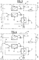
- the diet of the figure 3 is a variant of the diet 15 of the figure 2 . It comprises identically, and with the same operation, all the elements of the power supply 15 which are therefore designated by the same references on the figure 3 .
- the power supply 25 is also intended to be used with the telephone 1 not shown on the figure 3 .
- the power supply 25 differs from the power supply 15 in that it further comprises a controlled inverter switch 19 which can be implemented using transistors for example.
- This inverter 19 makes it possible to connect the input of the converter 16 selectively to the low-voltage power source connected to the cord 17 or the battery 10.
- the presence of the low voltage power source can be determined by the detection of its voltage at the terminals of the cord 17, for example using an amplifier amplifier operational circuit.
- the power supply is in the configuration of the power supply 15.
- the control circuit of the inverter 19 can cause the switching of the inverter 17 to connect the battery 10 to the input of the converter 16 In other words, the battery 10 then supplies the external device via the converter 16.
- This possibility is advantageous since the voltage across the battery 10 decreases progressively as a function of its discharge. Thus, it makes it possible to raise the voltage of the battery 10 to a level sufficient to continue to power the external device in the case where the voltage across the battery 10 becomes too low. This possibility therefore makes it possible to take fuller advantage of the storage capacity of the battery 10.
- the latter may also consist of a smaller number of battery cells to define a battery having a lower voltage. This results in a gain in weight and size.
- the battery 10 may consist of four 1.2-volt nickel-cadmium cells, instead of five in the example cited for 5. This results in a 4.8 Volt battery whose voltage varies between 3.6 Volts and 6 Volts depending on its level of charge. When it drops below 5 volts, the voltage of the battery 10 becomes insufficient to charge the battery 2 at a voltage of 4.2 volts taking into account the voltage drops introduced by the intermediate elements: diode 12, current limiting circuit 9, control circuit 4, etc ...
- the control circuit of the inverter 19 can be provided to connect the battery 10 to the input of the converter 16 as soon as the voltage of the battery 10 passes below 5 volts. Therefore, it is the output voltage - higher - of the converter 16 which supplies the battery 2. Moreover, the output voltage supplied by the converters 6 and 16 can be of the order of 6 or 7 volts, at the place of the aforementioned 8 or 9 volts in the case of power supply 5.
- the food 35 of the figure 4 is a variant of the diet 25 of the figure 3 . It comprises identically, and with the same operation, all the elements of the power supply 25 which are therefore designated by the same references on the figure 3 . In our example, the power supply 25 is also intended to be used with the telephone 1 not shown on the figure 4 .
- the power supply 35 differs from the power supply 25 in that it further comprises another controlled inverter switch 20 which can be implemented by means of transistors for example.
- This inverter 20 connects the low voltage power source connected to the cord 17 selectively to the input of the converter 16 via, if necessary, the inverter 19 or the cord 8 via, if appropriate, the current limiting circuit 9.
- the power supply 35 In the first position of the inverter 20, the power supply 35 is found in the configurations described above . In the other position, the low voltage power source supplies the external device via the current limiting circuit 9 and the battery 10, without passing through the converter 16.
- a control circuit - not shown - sets the inverter 20 in this other position when the voltage of the power source connected to the cord 17 is within an acceptable range to be applied directly to the external device and to the battery 10. This will avoid the loss of efficiency associated with the converter 16.
- this voltage range can be 5.5 to 7 volts.
- this variant can also be implemented in the absence of the inverter 19 for connecting the battery 10 to the input of the converter 16. In other words, this variant can be implemented on the power supply. 15 of the figure 2 . It suffices for this to connect the terminal of the switch 20 - which is connected to the figure 4 at one of the terminals of the inverter 19 - directly at the input of the converter 16.
- the power supply is provided to not charge the battery 10 , but only to power the external device, when the power supply is connected not to the mains by the cord 7, but only to a low-voltage energy source of less than 12 volts by the cord 17.
- the power supply when is optionally connected to a low voltage power source greater than or equal to 12 Volts or to the mains, the power supply preferably simultaneously ensures the charge of the battery 10 and the power supply of the external device connected to the cord 8 like this has been described previously. Nevertheless, when the external device is not connected to the cord 8, the power supply charges the battery 10 whatever the source of energy available at the input. If the current is not sufficient to allow ultra-fast charging, it can of course be realized more slowly.
- a power source having a voltage greater than or equal to 12 Volts generally corresponds to a motor vehicle battery which is capable of supplying a sufficient current to simultaneously charge the battery 10 and power the external device.
- a power source having a voltage of less than 12 volts generally corresponds to a source of low power which is then more advantageously to be used for the sole power supply of the external device. when it is connected to the cord 8.
- the low voltage source is a bicycle dynamo or a standard battery type R61 9 Volts, R12 4.5 Volts or similar.
- this variant is all the more justified by the fact that these batteries are themselves an energy storage element easily transportable by an individual: it is then more advantageous to directly power the outdoor device without intermediate storage in the battery 10 which necessarily implies yield losses as well as time.
- the power supply may include a manual switch allowing the user selectively to allow or prevent charging of the battery 10 from the input power source. Therefore, it can choose itself whether it wishes to power only the external device connected to the power supply or to simultaneously charge the battery 10.
- the power supplies 5, 15, 25 and 35 may all comprise a housing 23 which houses all of the circuits forming part of it, including the battery 10, with the plugs of the cords 7, 8 and, where appropriate, 17, which are accessible from outside the housing 23.
- the housing 23 has been represented symbolically in phantom in the figures.
- the battery 10 may be external to the housing 23 and removable.
- the power supply may comprise a connector - for example placed in a housing made in the housing 23 and accessible from outside the housing - to enable the battery 10 to be connected and disconnected. This variant has the advantage of being able to charge successively several batteries 10 and then use them successively to power the external device.
- a separate cord - including, if necessary, a current limiting circuit similar to that referenced 9 - to connect the external device to the battery 10, without the intermediary of the 23.
- the power supply in the housing 23 is used to recharge the battery 10 which can then be separated from the housing 23 and connected with the separate cord to the external device to power it.
- the cord 8 of the power supply in the housing 23 can even be removed in this case.
- the battery 10 can be replaced by any appropriate electrical energy storage means, preferably accepting to be loaded ultra-fast.
- This may include supercapacitors. It can be by example of supercapacitors with capacities of 3000 Farad marketed by the Korean company Ness.
- the invention can be implemented with a battery 10 or other electrical energy storage means not allowing an ultrafast load in which case the power supply of the invention may not be provided to be able to achieve this. type of charge.
- Another variant is to provide a solar panel 21 - for example 7.2 volts - on the housing 23 and which also charges the battery 10 and / or power the outdoor unit.
- a diode 22 can also be provided to prevent the battery 10, the battery 2 or other power source connected to the input of the power supply can be discharged into the solar panel.
- Such a solar panel can advantageously provide electrical energy in the absence of any other available source.
- cords with plugs 7, 8 and 17 can be replaced by any other suitable means for connecting the input power sources, as well as the external device.
- the battery 10 generally consists of several elementary accumulator cells connected in series to obtain the desired battery voltage - cf. examples cited in relation to the figures 1 and 3 . Therefore, the charging of the battery 10 is carried out conventionally on the battery 10 with its cells connected in series. As a variant, the charge of the battery 10 can be carried out individually for each of the cells of the battery 10. Such a variant is represented by the figure 5 and is based on the diet 5 of the figure 2 .
- the references 8 and 9 respectively denote the current limiting circuit and the cord used to connect the external device to be powered.
- the exemplary battery 10 comprises four elementary cells 10a-10d. Each cell 10a-10d corresponds to a charge control circuit 11a-11d.
- each of the load control circuits 11a-11d is to carry out an ultrafast load of the corresponding cell.
- the current is provided by a converter 6a which replaces the converter 6 of the power supply 2.
- the converter 6a differs from the converter 6 in that it delivers an adequate voltage to charge a cell of the battery, and not the battery as a whole .
- the load control circuits 11a-11d are similar to the control circuit 11 of the power supply 5, except for what they are each provided for the control of a single battery cell, instead of the entire battery.
- a series of controlled switches 27a-27c - for example MOS transistors - allow - when they are closed - to connect the cells in series so as to constitute the battery 10.
- Another series of switches Controlled 26a-26c - for example MOS transistors - allow - when closed - to connect a terminal of each battery cell - except the last referenced 10d - to ground, the other terminal of the cells being connected permanently to their respective load control circuit 11a-11d.
- the cell 10d is permanently connected to the ground.
- the terminal of the first cell 10a which is connected to its load control circuit 11a is also connected to the cord 8 via the current limiting circuit 9.
- a control circuit - not shown - opens the switches 27a-27c and close the switches 26a-26c. In this way, each of the cells 10a-10c is loaded through its load control circuit 11a-11c. On the contrary, when it comes to powering the external device connected to the cord 8, the control circuit opens the switches 26a-26c and close the switches 27a-27c. The voltage resulting from the series setting of the cells 10a-10d is then applied to the apparatus by means of the diode 13c and the current limiting circuit 9.
- the supply can be provided with an additional converter 6b if It is desired to be able to simultaneously charge the cells 10a-10d and supply the device connected to the cord 8 when the cord 7 is connected to the mains.
- the converter 6b also receives the input sector through the cord 7.
- the converter 6b provides a voltage output to directly power the device via the current limiting circuit 9.
- a diode 13b provides the coupling to the limiting circuit.
- the device according to the invention makes it possible to supply any kind of electrical appliance, in particular appliances that do not have a clean battery, unlike the mobile phone used as an example.
- the mobile phone used as an example can power a radio.
- the charge control circuit 11 and the battery 10 are eliminated in the power supplies 15 and 35. This simply results in a universal power supply allowing the power supply of the external device to be selected by the sector or by a low-voltage energy source, see by the solar panel 21 integrated in the housing 23. But the power supply no longer offers the possibility of clean storage of electrical energy.
- its weight is preferably less than or equal to three times, more preferably to one and a half times and even more preferably to one time the weight of the device that is intended to feed in the case where this device is a mobile phone or a pocket electronic diary.
- its weight is preferably less than or equal to 20%, more preferably 10% of the weight of the apparatus that it is intended to supply in the case where this device is a laptop.
- FIG. 1 illustrates the fact that the use of a buffer energy storage means 10 is independent of the possibility for the device of the invention to be powered from a mains supply or from a source of electrical energy low tension.
Landscapes
- Engineering & Computer Science (AREA)
- Power Engineering (AREA)
- Charge And Discharge Circuits For Batteries Or The Like (AREA)
- Power Sources (AREA)
- Secondary Cells (AREA)
- Dc-Dc Converters (AREA)
Applications Claiming Priority (3)
| Application Number | Priority Date | Filing Date | Title |
|---|---|---|---|
| FR0114538 | 2001-11-09 | ||
| FR0114538A FR2832262A1 (fr) | 2001-11-09 | 2001-11-09 | Procede et dispositif d'alimentation en energie electrique d'un appareil |
| PCT/FR2002/003841 WO2003041189A2 (fr) | 2001-11-09 | 2002-11-08 | Procede et dispositif d'alimentation en energie electrique d'un appareil |
Publications (2)
| Publication Number | Publication Date |
|---|---|
| EP1446855A2 EP1446855A2 (fr) | 2004-08-18 |
| EP1446855B1 true EP1446855B1 (fr) | 2018-04-18 |
Family
ID=8869254
Family Applications (1)
| Application Number | Title | Priority Date | Filing Date |
|---|---|---|---|
| EP02793218.5A Expired - Lifetime EP1446855B1 (fr) | 2001-11-09 | 2002-11-08 | Procede et dispositif d'alimentation en energie electrique d'un appareil |
Country Status (6)
| Country | Link |
|---|---|
| US (1) | US7408272B2 (enExample) |
| EP (1) | EP1446855B1 (enExample) |
| JP (1) | JP4261358B2 (enExample) |
| AU (1) | AU2002358880A1 (enExample) |
| FR (1) | FR2832262A1 (enExample) |
| WO (1) | WO2003041189A2 (enExample) |
Families Citing this family (462)
| Publication number | Priority date | Publication date | Assignee | Title |
|---|---|---|---|---|
| LU90584B1 (de) | 2000-05-17 | 2001-11-19 | Trefil Arbed Bissen S A | Drahtfaser |
| FR2832262A1 (fr) | 2001-11-09 | 2003-05-16 | France Telecom | Procede et dispositif d'alimentation en energie electrique d'un appareil |
| US9060770B2 (en) | 2003-05-20 | 2015-06-23 | Ethicon Endo-Surgery, Inc. | Robotically-driven surgical instrument with E-beam driver |
| US20070084897A1 (en) | 2003-05-20 | 2007-04-19 | Shelton Frederick E Iv | Articulating surgical stapling instrument incorporating a two-piece e-beam firing mechanism |
| US7535196B2 (en) * | 2004-01-22 | 2009-05-19 | Nec Corporation | Power apparatus and electronic equipment for cellular phone having main battery and attachable battery |
| US11998198B2 (en) | 2004-07-28 | 2024-06-04 | Cilag Gmbh International | Surgical stapling instrument incorporating a two-piece E-beam firing mechanism |
| US11890012B2 (en) | 2004-07-28 | 2024-02-06 | Cilag Gmbh International | Staple cartridge comprising cartridge body and attached support |
| US8215531B2 (en) | 2004-07-28 | 2012-07-10 | Ethicon Endo-Surgery, Inc. | Surgical stapling instrument having a medical substance dispenser |
| US9072535B2 (en) | 2011-05-27 | 2015-07-07 | Ethicon Endo-Surgery, Inc. | Surgical stapling instruments with rotatable staple deployment arrangements |
| CA2519606A1 (en) * | 2004-09-15 | 2006-03-15 | Belkin Corporation | Power supply system comprising rechargeable battery pack and attachment apparatus |
| US11246590B2 (en) | 2005-08-31 | 2022-02-15 | Cilag Gmbh International | Staple cartridge including staple drivers having different unfired heights |
| US9237891B2 (en) | 2005-08-31 | 2016-01-19 | Ethicon Endo-Surgery, Inc. | Robotically-controlled surgical stapling devices that produce formed staples having different lengths |
| US7934630B2 (en) | 2005-08-31 | 2011-05-03 | Ethicon Endo-Surgery, Inc. | Staple cartridges for forming staples having differing formed staple heights |
| US7669746B2 (en) | 2005-08-31 | 2010-03-02 | Ethicon Endo-Surgery, Inc. | Staple cartridges for forming staples having differing formed staple heights |
| US11484312B2 (en) | 2005-08-31 | 2022-11-01 | Cilag Gmbh International | Staple cartridge comprising a staple driver arrangement |
| US10159482B2 (en) | 2005-08-31 | 2018-12-25 | Ethicon Llc | Fastener cartridge assembly comprising a fixed anvil and different staple heights |
| US20070106317A1 (en) | 2005-11-09 | 2007-05-10 | Shelton Frederick E Iv | Hydraulically and electrically actuated articulation joints for surgical instruments |
| KR100731595B1 (ko) * | 2005-11-16 | 2007-06-22 | (주)에스피에스 | 휴대용 배터리 충전 및 비상 전원공급장치 |
| US7845537B2 (en) | 2006-01-31 | 2010-12-07 | Ethicon Endo-Surgery, Inc. | Surgical instrument having recording capabilities |
| US20120292367A1 (en) | 2006-01-31 | 2012-11-22 | Ethicon Endo-Surgery, Inc. | Robotically-controlled end effector |
| US11793518B2 (en) | 2006-01-31 | 2023-10-24 | Cilag Gmbh International | Powered surgical instruments with firing system lockout arrangements |
| US8708213B2 (en) | 2006-01-31 | 2014-04-29 | Ethicon Endo-Surgery, Inc. | Surgical instrument having a feedback system |
| US20110024477A1 (en) | 2009-02-06 | 2011-02-03 | Hall Steven G | Driven Surgical Stapler Improvements |
| US11278279B2 (en) | 2006-01-31 | 2022-03-22 | Cilag Gmbh International | Surgical instrument assembly |
| US7753904B2 (en) | 2006-01-31 | 2010-07-13 | Ethicon Endo-Surgery, Inc. | Endoscopic surgical instrument with a handle that can articulate with respect to the shaft |
| US8186555B2 (en) | 2006-01-31 | 2012-05-29 | Ethicon Endo-Surgery, Inc. | Motor-driven surgical cutting and fastening instrument with mechanical closure system |
| US11224427B2 (en) | 2006-01-31 | 2022-01-18 | Cilag Gmbh International | Surgical stapling system including a console and retraction assembly |
| US20110290856A1 (en) | 2006-01-31 | 2011-12-01 | Ethicon Endo-Surgery, Inc. | Robotically-controlled surgical instrument with force-feedback capabilities |
| US8820603B2 (en) | 2006-01-31 | 2014-09-02 | Ethicon Endo-Surgery, Inc. | Accessing data stored in a memory of a surgical instrument |
| US7989981B2 (en) * | 2006-02-02 | 2011-08-02 | Flextronics Ap, Llc | Power adaptor and storage unit for portable devices |
| US8992422B2 (en) | 2006-03-23 | 2015-03-31 | Ethicon Endo-Surgery, Inc. | Robotically-controlled endoscopic accessory channel |
| NL2000276C2 (nl) * | 2006-05-29 | 2007-11-30 | Fed Creations C V | Schakeling voor opladen van draagbare elektronica. |
| US8322455B2 (en) | 2006-06-27 | 2012-12-04 | Ethicon Endo-Surgery, Inc. | Manually driven surgical cutting and fastening instrument |
| US8485412B2 (en) | 2006-09-29 | 2013-07-16 | Ethicon Endo-Surgery, Inc. | Surgical staples having attached drivers and stapling instruments for deploying the same |
| US10568652B2 (en) | 2006-09-29 | 2020-02-25 | Ethicon Llc | Surgical staples having attached drivers of different heights and stapling instruments for deploying the same |
| US11980366B2 (en) | 2006-10-03 | 2024-05-14 | Cilag Gmbh International | Surgical instrument |
| US11291441B2 (en) | 2007-01-10 | 2022-04-05 | Cilag Gmbh International | Surgical instrument with wireless communication between control unit and remote sensor |
| US8632535B2 (en) | 2007-01-10 | 2014-01-21 | Ethicon Endo-Surgery, Inc. | Interlock and surgical instrument including same |
| US8652120B2 (en) | 2007-01-10 | 2014-02-18 | Ethicon Endo-Surgery, Inc. | Surgical instrument with wireless communication between control unit and sensor transponders |
| US8684253B2 (en) | 2007-01-10 | 2014-04-01 | Ethicon Endo-Surgery, Inc. | Surgical instrument with wireless communication between a control unit of a robotic system and remote sensor |
| US11039836B2 (en) | 2007-01-11 | 2021-06-22 | Cilag Gmbh International | Staple cartridge for use with a surgical stapling instrument |
| US20080169332A1 (en) | 2007-01-11 | 2008-07-17 | Shelton Frederick E | Surgical stapling device with a curved cutting member |
| US8727197B2 (en) | 2007-03-15 | 2014-05-20 | Ethicon Endo-Surgery, Inc. | Staple cartridge cavity configuration with cooperative surgical staple |
| US8368346B2 (en) | 2007-03-26 | 2013-02-05 | The Gillette Company | Portable energy storage and charging device |
| EP2130280A2 (en) * | 2007-03-26 | 2009-12-09 | The Gillette Company | Portable energy storage and charging device |
| US8893946B2 (en) | 2007-03-28 | 2014-11-25 | Ethicon Endo-Surgery, Inc. | Laparoscopic tissue thickness and clamp load measuring devices |
| US8931682B2 (en) | 2007-06-04 | 2015-01-13 | Ethicon Endo-Surgery, Inc. | Robotically-controlled shaft based rotary drive systems for surgical instruments |
| US11857181B2 (en) | 2007-06-04 | 2024-01-02 | Cilag Gmbh International | Robotically-controlled shaft based rotary drive systems for surgical instruments |
| US7753245B2 (en) | 2007-06-22 | 2010-07-13 | Ethicon Endo-Surgery, Inc. | Surgical stapling instruments |
| US11849941B2 (en) | 2007-06-29 | 2023-12-26 | Cilag Gmbh International | Staple cartridge having staple cavities extending at a transverse angle relative to a longitudinal cartridge axis |
| US9179912B2 (en) | 2008-02-14 | 2015-11-10 | Ethicon Endo-Surgery, Inc. | Robotically-controlled motorized surgical cutting and fastening instrument |
| US8636736B2 (en) | 2008-02-14 | 2014-01-28 | Ethicon Endo-Surgery, Inc. | Motorized surgical cutting and fastening instrument |
| US8573465B2 (en) | 2008-02-14 | 2013-11-05 | Ethicon Endo-Surgery, Inc. | Robotically-controlled surgical end effector system with rotary actuated closure systems |
| US8758391B2 (en) | 2008-02-14 | 2014-06-24 | Ethicon Endo-Surgery, Inc. | Interchangeable tools for surgical instruments |
| RU2493788C2 (ru) | 2008-02-14 | 2013-09-27 | Этикон Эндо-Серджери, Инк. | Хирургический режущий и крепежный инструмент, имеющий радиочастотные электроды |
| US7819298B2 (en) | 2008-02-14 | 2010-10-26 | Ethicon Endo-Surgery, Inc. | Surgical stapling apparatus with control features operable with one hand |
| US11986183B2 (en) | 2008-02-14 | 2024-05-21 | Cilag Gmbh International | Surgical cutting and fastening instrument comprising a plurality of sensors to measure an electrical parameter |
| US7866527B2 (en) | 2008-02-14 | 2011-01-11 | Ethicon Endo-Surgery, Inc. | Surgical stapling apparatus with interlockable firing system |
| US11272927B2 (en) | 2008-02-15 | 2022-03-15 | Cilag Gmbh International | Layer arrangements for surgical staple cartridges |
| US20130153641A1 (en) | 2008-02-15 | 2013-06-20 | Ethicon Endo-Surgery, Inc. | Releasable layer of material and surgical end effector having the same |
| US9005230B2 (en) | 2008-09-23 | 2015-04-14 | Ethicon Endo-Surgery, Inc. | Motorized surgical instrument |
| US9386983B2 (en) | 2008-09-23 | 2016-07-12 | Ethicon Endo-Surgery, Llc | Robotically-controlled motorized surgical instrument |
| US11648005B2 (en) | 2008-09-23 | 2023-05-16 | Cilag Gmbh International | Robotically-controlled motorized surgical instrument with an end effector |
| US8210411B2 (en) | 2008-09-23 | 2012-07-03 | Ethicon Endo-Surgery, Inc. | Motor-driven surgical cutting instrument |
| US8608045B2 (en) | 2008-10-10 | 2013-12-17 | Ethicon Endo-Sugery, Inc. | Powered surgical cutting and stapling apparatus with manually retractable firing system |
| US8517239B2 (en) | 2009-02-05 | 2013-08-27 | Ethicon Endo-Surgery, Inc. | Surgical stapling instrument comprising a magnetic element driver |
| JP2012517287A (ja) | 2009-02-06 | 2012-08-02 | エシコン・エンド−サージェリィ・インコーポレイテッド | 被駆動式手術用ステープラの改良 |
| US8444036B2 (en) | 2009-02-06 | 2013-05-21 | Ethicon Endo-Surgery, Inc. | Motor driven surgical fastener device with mechanisms for adjusting a tissue gap within the end effector |
| TWI458220B (zh) | 2009-03-30 | 2014-10-21 | Atomtech Energy & Ind Co Ltd | 電力供應器 |
| US8446037B2 (en) * | 2009-12-04 | 2013-05-21 | Kevin R. Williams | Energy storage system for peak-shaving of drilling rig power usage |
| US8220688B2 (en) | 2009-12-24 | 2012-07-17 | Ethicon Endo-Surgery, Inc. | Motor-driven surgical cutting instrument with electric actuator directional control assembly |
| US8851354B2 (en) | 2009-12-24 | 2014-10-07 | Ethicon Endo-Surgery, Inc. | Surgical cutting instrument that analyzes tissue thickness |
| US8170818B2 (en) | 2010-03-10 | 2012-05-01 | GM Global Technology Operations LLC | Battery state estimator using multiple sampling rates |
| US8783543B2 (en) | 2010-07-30 | 2014-07-22 | Ethicon Endo-Surgery, Inc. | Tissue acquisition arrangements and methods for surgical stapling devices |
| EP2424067A1 (en) * | 2010-08-26 | 2012-02-29 | ST-Ericsson SA | Power management circuit for a portable electronic device including USB functionality and method for doing the same |
| US11812965B2 (en) | 2010-09-30 | 2023-11-14 | Cilag Gmbh International | Layer of material for a surgical end effector |
| US9232941B2 (en) | 2010-09-30 | 2016-01-12 | Ethicon Endo-Surgery, Inc. | Tissue thickness compensator comprising a reservoir |
| US9364233B2 (en) | 2010-09-30 | 2016-06-14 | Ethicon Endo-Surgery, Llc | Tissue thickness compensators for circular surgical staplers |
| US12213666B2 (en) | 2010-09-30 | 2025-02-04 | Cilag Gmbh International | Tissue thickness compensator comprising layers |
| US9241714B2 (en) | 2011-04-29 | 2016-01-26 | Ethicon Endo-Surgery, Inc. | Tissue thickness compensator and method for making the same |
| US11298125B2 (en) | 2010-09-30 | 2022-04-12 | Cilag Gmbh International | Tissue stapler having a thickness compensator |
| US10945731B2 (en) | 2010-09-30 | 2021-03-16 | Ethicon Llc | Tissue thickness compensator comprising controlled release and expansion |
| US9629814B2 (en) | 2010-09-30 | 2017-04-25 | Ethicon Endo-Surgery, Llc | Tissue thickness compensator configured to redistribute compressive forces |
| US11925354B2 (en) | 2010-09-30 | 2024-03-12 | Cilag Gmbh International | Staple cartridge comprising staples positioned within a compressible portion thereof |
| US9320523B2 (en) | 2012-03-28 | 2016-04-26 | Ethicon Endo-Surgery, Llc | Tissue thickness compensator comprising tissue ingrowth features |
| US9113865B2 (en) | 2010-09-30 | 2015-08-25 | Ethicon Endo-Surgery, Inc. | Staple cartridge comprising a layer |
| US10405854B2 (en) | 2010-09-30 | 2019-09-10 | Ethicon Llc | Surgical stapling cartridge with layer retention features |
| US8695866B2 (en) | 2010-10-01 | 2014-04-15 | Ethicon Endo-Surgery, Inc. | Surgical instrument having a power control circuit |
| GB2484773B (en) * | 2010-10-21 | 2013-09-11 | Chervon Hk Ltd | Battery charging system having multiple charging modes |
| JP5348697B2 (ja) * | 2010-10-22 | 2013-11-20 | Necアクセステクニカ株式会社 | 電力パス切り替え方法および電力パス切替回路 |
| US8400113B2 (en) | 2011-02-11 | 2013-03-19 | Mark Andrew Waring | Battery enhanced, smart grid add-on for appliance |
| WO2012127649A1 (ja) * | 2011-03-23 | 2012-09-27 | トヨタ自動車株式会社 | アダプタ、ならびにそれを用いて電力供給を行なう車両および方法 |
| BR112013027794B1 (pt) | 2011-04-29 | 2020-12-15 | Ethicon Endo-Surgery, Inc | Conjunto de cartucho de grampos |
| US9158336B2 (en) * | 2011-05-06 | 2015-10-13 | Micron Technology, Inc. | Cases for tablet computers and methods |
| US11207064B2 (en) | 2011-05-27 | 2021-12-28 | Cilag Gmbh International | Automated end effector component reloading system for use with a robotic system |
| DE102011077660A1 (de) * | 2011-06-16 | 2012-12-20 | Meiko Maschinenbau Gmbh & Co. Kg | Reinigungsvorrichtung mit Energiespeicher |
| JP5152543B1 (ja) * | 2011-08-29 | 2013-02-27 | 有限会社 加納 | 微弱電力の充電装置 |
| US9044230B2 (en) | 2012-02-13 | 2015-06-02 | Ethicon Endo-Surgery, Inc. | Surgical cutting and fastening instrument with apparatus for determining cartridge and firing motion status |
| DK2815483T3 (da) * | 2012-02-17 | 2022-02-28 | Milwaukee Electric Tool Corp | Flerrumsatterioplader |
| CN104379068B (zh) | 2012-03-28 | 2017-09-22 | 伊西康内外科公司 | 包括组织厚度补偿件的保持器组件 |
| MX350846B (es) | 2012-03-28 | 2017-09-22 | Ethicon Endo Surgery Inc | Compensador de grosor de tejido que comprende cápsulas que definen un ambiente de baja presión. |
| MX358135B (es) | 2012-03-28 | 2018-08-06 | Ethicon Endo Surgery Inc | Compensador de grosor de tejido que comprende una pluralidad de capas. |
| JP6062162B2 (ja) * | 2012-06-07 | 2017-01-18 | シャープ株式会社 | 充放電装置 |
| US9101358B2 (en) | 2012-06-15 | 2015-08-11 | Ethicon Endo-Surgery, Inc. | Articulatable surgical instrument comprising a firing drive |
| US9282974B2 (en) | 2012-06-28 | 2016-03-15 | Ethicon Endo-Surgery, Llc | Empty clip cartridge lockout |
| US11197671B2 (en) | 2012-06-28 | 2021-12-14 | Cilag Gmbh International | Stapling assembly comprising a lockout |
| BR112014032776B1 (pt) | 2012-06-28 | 2021-09-08 | Ethicon Endo-Surgery, Inc | Sistema de instrumento cirúrgico e kit cirúrgico para uso com um sistema de instrumento cirúrgico |
| JP6290201B2 (ja) | 2012-06-28 | 2018-03-07 | エシコン・エンド−サージェリィ・インコーポレイテッドEthicon Endo−Surgery,Inc. | 空クリップカートリッジ用のロックアウト |
| US9226751B2 (en) | 2012-06-28 | 2016-01-05 | Ethicon Endo-Surgery, Inc. | Surgical instrument system including replaceable end effectors |
| US9289256B2 (en) | 2012-06-28 | 2016-03-22 | Ethicon Endo-Surgery, Llc | Surgical end effectors having angled tissue-contacting surfaces |
| US9204879B2 (en) | 2012-06-28 | 2015-12-08 | Ethicon Endo-Surgery, Inc. | Flexible drive member |
| US20140001231A1 (en) | 2012-06-28 | 2014-01-02 | Ethicon Endo-Surgery, Inc. | Firing system lockout arrangements for surgical instruments |
| US12383267B2 (en) | 2012-06-28 | 2025-08-12 | Cilag Gmbh International | Robotically powered surgical device with manually-actuatable reversing system |
| HUE029084T2 (en) * | 2012-10-10 | 2017-02-28 | Grieshaber Vega Kg | power source |
| TW201417056A (zh) * | 2012-10-16 | 2014-05-01 | 桓科股份有限公司 | 能快速充電之警示設備 |
| EP2747298A1 (en) * | 2012-12-18 | 2014-06-25 | Gigastone Corporation | Wireless hotpoint device usable as electronic device charger |
| RU2669463C2 (ru) | 2013-03-01 | 2018-10-11 | Этикон Эндо-Серджери, Инк. | Хирургический инструмент с мягким упором |
| MX368026B (es) | 2013-03-01 | 2019-09-12 | Ethicon Endo Surgery Inc | Instrumento quirúrgico articulable con vías conductoras para la comunicación de la señal. |
| US9629629B2 (en) | 2013-03-14 | 2017-04-25 | Ethicon Endo-Surgey, LLC | Control systems for surgical instruments |
| US9351726B2 (en) | 2013-03-14 | 2016-05-31 | Ethicon Endo-Surgery, Llc | Articulation control system for articulatable surgical instruments |
| US9801626B2 (en) | 2013-04-16 | 2017-10-31 | Ethicon Llc | Modular motor driven surgical instruments with alignment features for aligning rotary drive shafts with surgical end effector shafts |
| BR112015026109B1 (pt) | 2013-04-16 | 2022-02-22 | Ethicon Endo-Surgery, Inc | Instrumento cirúrgico |
| US20150053737A1 (en) | 2013-08-23 | 2015-02-26 | Ethicon Endo-Surgery, Inc. | End effector detection systems for surgical instruments |
| MX369362B (es) | 2013-08-23 | 2019-11-06 | Ethicon Endo Surgery Llc | Dispositivos de retraccion de miembros de disparo para instrumentos quirurgicos electricos. |
| CN104734261B (zh) * | 2013-12-20 | 2017-02-22 | 中国移动通信集团甘肃有限公司 | 基于四网融合的室内供电开关电源及其实现方法 |
| US9962161B2 (en) | 2014-02-12 | 2018-05-08 | Ethicon Llc | Deliverable surgical instrument |
| BR112016019387B1 (pt) | 2014-02-24 | 2022-11-29 | Ethicon Endo-Surgery, Llc | Sistema de instrumento cirúrgico e cartucho de prendedores para uso com um instrumento cirúrgico de fixação |
| US9750499B2 (en) | 2014-03-26 | 2017-09-05 | Ethicon Llc | Surgical stapling instrument system |
| US10013049B2 (en) | 2014-03-26 | 2018-07-03 | Ethicon Llc | Power management through sleep options of segmented circuit and wake up control |
| US12232723B2 (en) | 2014-03-26 | 2025-02-25 | Cilag Gmbh International | Systems and methods for controlling a segmented circuit |
| BR112016021943B1 (pt) | 2014-03-26 | 2022-06-14 | Ethicon Endo-Surgery, Llc | Instrumento cirúrgico para uso por um operador em um procedimento cirúrgico |
| US20150272557A1 (en) | 2014-03-26 | 2015-10-01 | Ethicon Endo-Surgery, Inc. | Modular surgical instrument system |
| JP6532889B2 (ja) | 2014-04-16 | 2019-06-19 | エシコン エルエルシーEthicon LLC | 締結具カートリッジ組立体及びステープル保持具カバー配置構成 |
| US20150297223A1 (en) | 2014-04-16 | 2015-10-22 | Ethicon Endo-Surgery, Inc. | Fastener cartridges including extensions having different configurations |
| CN106456158B (zh) | 2014-04-16 | 2019-02-05 | 伊西康内外科有限责任公司 | 包括非一致紧固件的紧固件仓 |
| US10561422B2 (en) | 2014-04-16 | 2020-02-18 | Ethicon Llc | Fastener cartridge comprising deployable tissue engaging members |
| US10327764B2 (en) | 2014-09-26 | 2019-06-25 | Ethicon Llc | Method for creating a flexible staple line |
| CN106456176B (zh) | 2014-04-16 | 2019-06-28 | 伊西康内外科有限责任公司 | 包括具有不同构型的延伸部的紧固件仓 |
| CN103944250A (zh) * | 2014-04-21 | 2014-07-23 | 国家电网公司 | 一种单相智能电能表电池防钝化电路 |
| US9800075B2 (en) | 2014-06-04 | 2017-10-24 | Societe Bic | Smart charging cable and method for operating a portable electronic device |
| JP2017525327A (ja) * | 2014-06-24 | 2017-08-31 | アップル インコーポレイテッド | ポータブル電子デバイスのための単一インダクタ複数出力のバッテリ充電器 |
| KR101872655B1 (ko) | 2014-09-02 | 2018-06-28 | 애플 인크. | 부스트 바이패스를 이용한 다중-위상 배터리 충전 |
| BR112017004361B1 (pt) | 2014-09-05 | 2023-04-11 | Ethicon Llc | Sistema eletrônico para um instrumento cirúrgico |
| US9724094B2 (en) | 2014-09-05 | 2017-08-08 | Ethicon Llc | Adjunct with integrated sensors to quantify tissue compression |
| US11311294B2 (en) | 2014-09-05 | 2022-04-26 | Cilag Gmbh International | Powered medical device including measurement of closure state of jaws |
| US10105142B2 (en) | 2014-09-18 | 2018-10-23 | Ethicon Llc | Surgical stapler with plurality of cutting elements |
| US11523821B2 (en) | 2014-09-26 | 2022-12-13 | Cilag Gmbh International | Method for creating a flexible staple line |
| JP6648119B2 (ja) | 2014-09-26 | 2020-02-14 | エシコン エルエルシーEthicon LLC | 外科ステープル留めバットレス及び付属物材料 |
| US10076325B2 (en) | 2014-10-13 | 2018-09-18 | Ethicon Llc | Surgical stapling apparatus comprising a tissue stop |
| US9924944B2 (en) | 2014-10-16 | 2018-03-27 | Ethicon Llc | Staple cartridge comprising an adjunct material |
| US11141153B2 (en) | 2014-10-29 | 2021-10-12 | Cilag Gmbh International | Staple cartridges comprising driver arrangements |
| US10517594B2 (en) | 2014-10-29 | 2019-12-31 | Ethicon Llc | Cartridge assemblies for surgical staplers |
| US9844376B2 (en) | 2014-11-06 | 2017-12-19 | Ethicon Llc | Staple cartridge comprising a releasable adjunct material |
| US10736636B2 (en) | 2014-12-10 | 2020-08-11 | Ethicon Llc | Articulatable surgical instrument system |
| CN104485812A (zh) * | 2014-12-17 | 2015-04-01 | 镇江市高等专科学校 | 电源适配器老化烧机装置 |
| US10245027B2 (en) | 2014-12-18 | 2019-04-02 | Ethicon Llc | Surgical instrument with an anvil that is selectively movable about a discrete non-movable axis relative to a staple cartridge |
| US10188385B2 (en) | 2014-12-18 | 2019-01-29 | Ethicon Llc | Surgical instrument system comprising lockable systems |
| US9844374B2 (en) | 2014-12-18 | 2017-12-19 | Ethicon Llc | Surgical instrument systems comprising an articulatable end effector and means for adjusting the firing stroke of a firing member |
| US9844375B2 (en) | 2014-12-18 | 2017-12-19 | Ethicon Llc | Drive arrangements for articulatable surgical instruments |
| RU2703684C2 (ru) | 2014-12-18 | 2019-10-21 | ЭТИКОН ЭНДО-СЕРДЖЕРИ, ЭлЭлСи | Хирургический инструмент с упором, который выполнен с возможностью избирательного перемещения относительно кассеты со скобами вокруг дискретной неподвижной оси |
| US10085748B2 (en) | 2014-12-18 | 2018-10-02 | Ethicon Llc | Locking arrangements for detachable shaft assemblies with articulatable surgical end effectors |
| US9987000B2 (en) | 2014-12-18 | 2018-06-05 | Ethicon Llc | Surgical instrument assembly comprising a flexible articulation system |
| CN107872967B (zh) * | 2015-02-27 | 2020-08-11 | 伊西康有限责任公司 | 实现电池充电紧急解决方案的充电系统 |
| US10159483B2 (en) * | 2015-02-27 | 2018-12-25 | Ethicon Llc | Surgical apparatus configured to track an end-of-life parameter |
| US11154301B2 (en) | 2015-02-27 | 2021-10-26 | Cilag Gmbh International | Modular stapling assembly |
| US10180463B2 (en) | 2015-02-27 | 2019-01-15 | Ethicon Llc | Surgical apparatus configured to assess whether a performance parameter of the surgical apparatus is within an acceptable performance band |
| US9901342B2 (en) | 2015-03-06 | 2018-02-27 | Ethicon Endo-Surgery, Llc | Signal and power communication system positioned on a rotatable shaft |
| JP2020121162A (ja) | 2015-03-06 | 2020-08-13 | エシコン エルエルシーEthicon LLC | 測定の安定性要素、クリープ要素、及び粘弾性要素を決定するためのセンサデータの時間依存性評価 |
| US9924961B2 (en) | 2015-03-06 | 2018-03-27 | Ethicon Endo-Surgery, Llc | Interactive feedback system for powered surgical instruments |
| US10687806B2 (en) | 2015-03-06 | 2020-06-23 | Ethicon Llc | Adaptive tissue compression techniques to adjust closure rates for multiple tissue types |
| US9808246B2 (en) | 2015-03-06 | 2017-11-07 | Ethicon Endo-Surgery, Llc | Method of operating a powered surgical instrument |
| US10245033B2 (en) | 2015-03-06 | 2019-04-02 | Ethicon Llc | Surgical instrument comprising a lockable battery housing |
| US10617412B2 (en) | 2015-03-06 | 2020-04-14 | Ethicon Llc | System for detecting the mis-insertion of a staple cartridge into a surgical stapler |
| US10441279B2 (en) | 2015-03-06 | 2019-10-15 | Ethicon Llc | Multiple level thresholds to modify operation of powered surgical instruments |
| US10548504B2 (en) | 2015-03-06 | 2020-02-04 | Ethicon Llc | Overlaid multi sensor radio frequency (RF) electrode system to measure tissue compression |
| US9993248B2 (en) | 2015-03-06 | 2018-06-12 | Ethicon Endo-Surgery, Llc | Smart sensors with local signal processing |
| US10390825B2 (en) | 2015-03-31 | 2019-08-27 | Ethicon Llc | Surgical instrument with progressive rotary drive systems |
| US10097017B2 (en) | 2015-06-24 | 2018-10-09 | Apple Inc. | Systems and methods for bidirectional two-port battery charging with boost functionality |
| US11058425B2 (en) | 2015-08-17 | 2021-07-13 | Ethicon Llc | Implantable layers for a surgical instrument |
| US10327769B2 (en) | 2015-09-23 | 2019-06-25 | Ethicon Llc | Surgical stapler having motor control based on a drive system component |
| US10363036B2 (en) | 2015-09-23 | 2019-07-30 | Ethicon Llc | Surgical stapler having force-based motor control |
| US10238386B2 (en) | 2015-09-23 | 2019-03-26 | Ethicon Llc | Surgical stapler having motor control based on an electrical parameter related to a motor current |
| US10105139B2 (en) | 2015-09-23 | 2018-10-23 | Ethicon Llc | Surgical stapler having downstream current-based motor control |
| US10299878B2 (en) | 2015-09-25 | 2019-05-28 | Ethicon Llc | Implantable adjunct systems for determining adjunct skew |
| CN105141020A (zh) * | 2015-09-29 | 2015-12-09 | 大连罗宾森电源设备有限公司 | 一种模块集成化的单双枪交流充电桩 |
| US11890015B2 (en) | 2015-09-30 | 2024-02-06 | Cilag Gmbh International | Compressible adjunct with crossing spacer fibers |
| US10980539B2 (en) | 2015-09-30 | 2021-04-20 | Ethicon Llc | Implantable adjunct comprising bonded layers |
| US10736633B2 (en) | 2015-09-30 | 2020-08-11 | Ethicon Llc | Compressible adjunct with looping members |
| US10172620B2 (en) | 2015-09-30 | 2019-01-08 | Ethicon Llc | Compressible adjuncts with bonding nodes |
| US10368865B2 (en) | 2015-12-30 | 2019-08-06 | Ethicon Llc | Mechanisms for compensating for drivetrain failure in powered surgical instruments |
| US10292704B2 (en) | 2015-12-30 | 2019-05-21 | Ethicon Llc | Mechanisms for compensating for battery pack failure in powered surgical instruments |
| US10265068B2 (en) | 2015-12-30 | 2019-04-23 | Ethicon Llc | Surgical instruments with separable motors and motor control circuits |
| US10413291B2 (en) | 2016-02-09 | 2019-09-17 | Ethicon Llc | Surgical instrument articulation mechanism with slotted secondary constraint |
| US11213293B2 (en) | 2016-02-09 | 2022-01-04 | Cilag Gmbh International | Articulatable surgical instruments with single articulation link arrangements |
| BR112018016098B1 (pt) | 2016-02-09 | 2023-02-23 | Ethicon Llc | Instrumento cirúrgico |
| US10448948B2 (en) | 2016-02-12 | 2019-10-22 | Ethicon Llc | Mechanisms for compensating for drivetrain failure in powered surgical instruments |
| US11224426B2 (en) | 2016-02-12 | 2022-01-18 | Cilag Gmbh International | Mechanisms for compensating for drivetrain failure in powered surgical instruments |
| US10258331B2 (en) | 2016-02-12 | 2019-04-16 | Ethicon Llc | Mechanisms for compensating for drivetrain failure in powered surgical instruments |
| US11064997B2 (en) | 2016-04-01 | 2021-07-20 | Cilag Gmbh International | Surgical stapling instrument |
| US10617413B2 (en) | 2016-04-01 | 2020-04-14 | Ethicon Llc | Closure system arrangements for surgical cutting and stapling devices with separate and distinct firing shafts |
| US10456137B2 (en) | 2016-04-15 | 2019-10-29 | Ethicon Llc | Staple formation detection mechanisms |
| US10405859B2 (en) | 2016-04-15 | 2019-09-10 | Ethicon Llc | Surgical instrument with adjustable stop/start control during a firing motion |
| US10828028B2 (en) | 2016-04-15 | 2020-11-10 | Ethicon Llc | Surgical instrument with multiple program responses during a firing motion |
| US10357247B2 (en) | 2016-04-15 | 2019-07-23 | Ethicon Llc | Surgical instrument with multiple program responses during a firing motion |
| US11607239B2 (en) | 2016-04-15 | 2023-03-21 | Cilag Gmbh International | Systems and methods for controlling a surgical stapling and cutting instrument |
| US11179150B2 (en) | 2016-04-15 | 2021-11-23 | Cilag Gmbh International | Systems and methods for controlling a surgical stapling and cutting instrument |
| US10492783B2 (en) | 2016-04-15 | 2019-12-03 | Ethicon, Llc | Surgical instrument with improved stop/start control during a firing motion |
| US10426467B2 (en) | 2016-04-15 | 2019-10-01 | Ethicon Llc | Surgical instrument with detection sensors |
| US10335145B2 (en) | 2016-04-15 | 2019-07-02 | Ethicon Llc | Modular surgical instrument with configurable operating mode |
| US11317917B2 (en) | 2016-04-18 | 2022-05-03 | Cilag Gmbh International | Surgical stapling system comprising a lockable firing assembly |
| US10433840B2 (en) | 2016-04-18 | 2019-10-08 | Ethicon Llc | Surgical instrument comprising a replaceable cartridge jaw |
| US20170296173A1 (en) | 2016-04-18 | 2017-10-19 | Ethicon Endo-Surgery, Llc | Method for operating a surgical instrument |
| US10500000B2 (en) | 2016-08-16 | 2019-12-10 | Ethicon Llc | Surgical tool with manual control of end effector jaws |
| JP6654535B2 (ja) * | 2016-09-21 | 2020-02-26 | 日立オートモティブシステムズ株式会社 | 負荷駆動装置 |
| US10778026B2 (en) | 2016-09-23 | 2020-09-15 | Apple Inc. | Multi-phase buck-boost charger |
| US10881401B2 (en) | 2016-12-21 | 2021-01-05 | Ethicon Llc | Staple firing member comprising a missing cartridge and/or spent cartridge lockout |
| US10758230B2 (en) | 2016-12-21 | 2020-09-01 | Ethicon Llc | Surgical instrument with primary and safety processors |
| US10426471B2 (en) | 2016-12-21 | 2019-10-01 | Ethicon Llc | Surgical instrument with multiple failure response modes |
| US10639035B2 (en) | 2016-12-21 | 2020-05-05 | Ethicon Llc | Surgical stapling instruments and replaceable tool assemblies thereof |
| US10779823B2 (en) | 2016-12-21 | 2020-09-22 | Ethicon Llc | Firing member pin angle |
| CN110099619B (zh) | 2016-12-21 | 2022-07-15 | 爱惜康有限责任公司 | 用于外科端部执行器和可替换工具组件的闭锁装置 |
| US20180168609A1 (en) | 2016-12-21 | 2018-06-21 | Ethicon Endo-Surgery, Llc | Firing assembly comprising a fuse |
| CN110114014B (zh) | 2016-12-21 | 2022-08-09 | 爱惜康有限责任公司 | 包括端部执行器闭锁件和击发组件闭锁件的外科器械系统 |
| JP7010957B2 (ja) | 2016-12-21 | 2022-01-26 | エシコン エルエルシー | ロックアウトを備えるシャフトアセンブリ |
| US11134942B2 (en) | 2016-12-21 | 2021-10-05 | Cilag Gmbh International | Surgical stapling instruments and staple-forming anvils |
| US10918385B2 (en) | 2016-12-21 | 2021-02-16 | Ethicon Llc | Surgical system comprising a firing member rotatable into an articulation state to articulate an end effector of the surgical system |
| US10499914B2 (en) | 2016-12-21 | 2019-12-10 | Ethicon Llc | Staple forming pocket arrangements |
| US10617414B2 (en) | 2016-12-21 | 2020-04-14 | Ethicon Llc | Closure member arrangements for surgical instruments |
| JP2020501815A (ja) | 2016-12-21 | 2020-01-23 | エシコン エルエルシーEthicon LLC | 外科用ステープル留めシステム |
| US20180168623A1 (en) | 2016-12-21 | 2018-06-21 | Ethicon Endo-Surgery, Llc | Surgical stapling systems |
| JP7010956B2 (ja) | 2016-12-21 | 2022-01-26 | エシコン エルエルシー | 組織をステープル留めする方法 |
| US20180168615A1 (en) | 2016-12-21 | 2018-06-21 | Ethicon Endo-Surgery, Llc | Method of deforming staples from two different types of staple cartridges with the same surgical stapling instrument |
| MX2019007311A (es) | 2016-12-21 | 2019-11-18 | Ethicon Llc | Sistemas de engrapado quirurgico. |
| US10667811B2 (en) | 2016-12-21 | 2020-06-02 | Ethicon Llc | Surgical stapling instruments and staple-forming anvils |
| US11419606B2 (en) | 2016-12-21 | 2022-08-23 | Cilag Gmbh International | Shaft assembly comprising a clutch configured to adapt the output of a rotary firing member to two different systems |
| US11090048B2 (en) | 2016-12-21 | 2021-08-17 | Cilag Gmbh International | Method for resetting a fuse of a surgical instrument shaft |
| US10568626B2 (en) | 2016-12-21 | 2020-02-25 | Ethicon Llc | Surgical instruments with jaw opening features for increasing a jaw opening distance |
| CN106849751A (zh) * | 2017-03-01 | 2017-06-13 | 西北工业大学 | 一种运动自行车发电蓄电装置 |
| DE102017112663A1 (de) * | 2017-06-08 | 2018-12-13 | Vorwerk & Co. Interholding Gmbh | Verfahren zum Betrieb eines einen Akkumulator aufweisenden Haushaltsgerätes |
| US10327767B2 (en) | 2017-06-20 | 2019-06-25 | Ethicon Llc | Control of motor velocity of a surgical stapling and cutting instrument based on angle of articulation |
| US11653914B2 (en) | 2017-06-20 | 2023-05-23 | Cilag Gmbh International | Systems and methods for controlling motor velocity of a surgical stapling and cutting instrument according to articulation angle of end effector |
| US10881396B2 (en) | 2017-06-20 | 2021-01-05 | Ethicon Llc | Surgical instrument with variable duration trigger arrangement |
| US10779820B2 (en) | 2017-06-20 | 2020-09-22 | Ethicon Llc | Systems and methods for controlling motor speed according to user input for a surgical instrument |
| US10390841B2 (en) | 2017-06-20 | 2019-08-27 | Ethicon Llc | Control of motor velocity of a surgical stapling and cutting instrument based on angle of articulation |
| USD890784S1 (en) | 2017-06-20 | 2020-07-21 | Ethicon Llc | Display panel with changeable graphical user interface |
| US10888321B2 (en) | 2017-06-20 | 2021-01-12 | Ethicon Llc | Systems and methods for controlling velocity of a displacement member of a surgical stapling and cutting instrument |
| US11071554B2 (en) | 2017-06-20 | 2021-07-27 | Cilag Gmbh International | Closed loop feedback control of motor velocity of a surgical stapling and cutting instrument based on magnitude of velocity error measurements |
| US11382638B2 (en) | 2017-06-20 | 2022-07-12 | Cilag Gmbh International | Closed loop feedback control of motor velocity of a surgical stapling and cutting instrument based on measured time over a specified displacement distance |
| US10624633B2 (en) | 2017-06-20 | 2020-04-21 | Ethicon Llc | Systems and methods for controlling motor velocity of a surgical stapling and cutting instrument |
| US10307170B2 (en) | 2017-06-20 | 2019-06-04 | Ethicon Llc | Method for closed loop control of motor velocity of a surgical stapling and cutting instrument |
| US11090046B2 (en) | 2017-06-20 | 2021-08-17 | Cilag Gmbh International | Systems and methods for controlling displacement member motion of a surgical stapling and cutting instrument |
| US12490980B2 (en) | 2017-06-20 | 2025-12-09 | Cilag Gmbh International | Surgical instrument having controllable articulation velocity |
| US10980537B2 (en) | 2017-06-20 | 2021-04-20 | Ethicon Llc | Closed loop feedback control of motor velocity of a surgical stapling and cutting instrument based on measured time over a specified number of shaft rotations |
| US11517325B2 (en) | 2017-06-20 | 2022-12-06 | Cilag Gmbh International | Closed loop feedback control of motor velocity of a surgical stapling and cutting instrument based on measured displacement distance traveled over a specified time interval |
| US10368864B2 (en) | 2017-06-20 | 2019-08-06 | Ethicon Llc | Systems and methods for controlling displaying motor velocity for a surgical instrument |
| US10813639B2 (en) | 2017-06-20 | 2020-10-27 | Ethicon Llc | Closed loop feedback control of motor velocity of a surgical stapling and cutting instrument based on system conditions |
| US10881399B2 (en) | 2017-06-20 | 2021-01-05 | Ethicon Llc | Techniques for adaptive control of motor velocity of a surgical stapling and cutting instrument |
| USD879808S1 (en) | 2017-06-20 | 2020-03-31 | Ethicon Llc | Display panel with graphical user interface |
| US10646220B2 (en) | 2017-06-20 | 2020-05-12 | Ethicon Llc | Systems and methods for controlling displacement member velocity for a surgical instrument |
| USD879809S1 (en) | 2017-06-20 | 2020-03-31 | Ethicon Llc | Display panel with changeable graphical user interface |
| US10993716B2 (en) | 2017-06-27 | 2021-05-04 | Ethicon Llc | Surgical anvil arrangements |
| US11324503B2 (en) | 2017-06-27 | 2022-05-10 | Cilag Gmbh International | Surgical firing member arrangements |
| US11090049B2 (en) | 2017-06-27 | 2021-08-17 | Cilag Gmbh International | Staple forming pocket arrangements |
| US10772629B2 (en) | 2017-06-27 | 2020-09-15 | Ethicon Llc | Surgical anvil arrangements |
| US10856869B2 (en) | 2017-06-27 | 2020-12-08 | Ethicon Llc | Surgical anvil arrangements |
| US11266405B2 (en) | 2017-06-27 | 2022-03-08 | Cilag Gmbh International | Surgical anvil manufacturing methods |
| US10903685B2 (en) | 2017-06-28 | 2021-01-26 | Ethicon Llc | Surgical shaft assemblies with slip ring assemblies forming capacitive channels |
| US11259805B2 (en) | 2017-06-28 | 2022-03-01 | Cilag Gmbh International | Surgical instrument comprising firing member supports |
| US20190000461A1 (en) | 2017-06-28 | 2019-01-03 | Ethicon Llc | Surgical cutting and fastening devices with pivotable anvil with a tissue locating arrangement in close proximity to an anvil pivot axis |
| US11564686B2 (en) | 2017-06-28 | 2023-01-31 | Cilag Gmbh International | Surgical shaft assemblies with flexible interfaces |
| USD854151S1 (en) | 2017-06-28 | 2019-07-16 | Ethicon Llc | Surgical instrument shaft |
| US10716614B2 (en) | 2017-06-28 | 2020-07-21 | Ethicon Llc | Surgical shaft assemblies with slip ring assemblies with increased contact pressure |
| BR112019027065B1 (pt) | 2017-06-28 | 2023-12-26 | Ethicon Llc | Instrumento cirúrgico e sistema cirúrgico |
| USD869655S1 (en) | 2017-06-28 | 2019-12-10 | Ethicon Llc | Surgical fastener cartridge |
| USD906355S1 (en) | 2017-06-28 | 2020-12-29 | Ethicon Llc | Display screen or portion thereof with a graphical user interface for a surgical instrument |
| US10211586B2 (en) | 2017-06-28 | 2019-02-19 | Ethicon Llc | Surgical shaft assemblies with watertight housings |
| US11000279B2 (en) | 2017-06-28 | 2021-05-11 | Ethicon Llc | Surgical instrument comprising an articulation system ratio |
| US10765427B2 (en) | 2017-06-28 | 2020-09-08 | Ethicon Llc | Method for articulating a surgical instrument |
| EP4070740B1 (en) | 2017-06-28 | 2025-03-26 | Cilag GmbH International | Surgical instrument comprising selectively actuatable rotatable couplers |
| US11246592B2 (en) | 2017-06-28 | 2022-02-15 | Cilag Gmbh International | Surgical instrument comprising an articulation system lockable to a frame |
| USD851762S1 (en) | 2017-06-28 | 2019-06-18 | Ethicon Llc | Anvil |
| US10398434B2 (en) | 2017-06-29 | 2019-09-03 | Ethicon Llc | Closed loop velocity control of closure member for robotic surgical instrument |
| US10898183B2 (en) | 2017-06-29 | 2021-01-26 | Ethicon Llc | Robotic surgical instrument with closed loop feedback techniques for advancement of closure member during firing |
| US11007022B2 (en) | 2017-06-29 | 2021-05-18 | Ethicon Llc | Closed loop velocity control techniques based on sensed tissue parameters for robotic surgical instrument |
| US10932772B2 (en) | 2017-06-29 | 2021-03-02 | Ethicon Llc | Methods for closed loop velocity control for robotic surgical instrument |
| US10258418B2 (en) | 2017-06-29 | 2019-04-16 | Ethicon Llc | System for controlling articulation forces |
| US11304695B2 (en) | 2017-08-03 | 2022-04-19 | Cilag Gmbh International | Surgical system shaft interconnection |
| US11471155B2 (en) | 2017-08-03 | 2022-10-18 | Cilag Gmbh International | Surgical system bailout |
| US11974742B2 (en) | 2017-08-03 | 2024-05-07 | Cilag Gmbh International | Surgical system comprising an articulation bailout |
| US11944300B2 (en) | 2017-08-03 | 2024-04-02 | Cilag Gmbh International | Method for operating a surgical system bailout |
| US10765429B2 (en) | 2017-09-29 | 2020-09-08 | Ethicon Llc | Systems and methods for providing alerts according to the operational state of a surgical instrument |
| US11399829B2 (en) | 2017-09-29 | 2022-08-02 | Cilag Gmbh International | Systems and methods of initiating a power shutdown mode for a surgical instrument |
| USD907648S1 (en) | 2017-09-29 | 2021-01-12 | Ethicon Llc | Display screen or portion thereof with animated graphical user interface |
| USD907647S1 (en) | 2017-09-29 | 2021-01-12 | Ethicon Llc | Display screen or portion thereof with animated graphical user interface |
| US10796471B2 (en) | 2017-09-29 | 2020-10-06 | Ethicon Llc | Systems and methods of displaying a knife position for a surgical instrument |
| US10743872B2 (en) | 2017-09-29 | 2020-08-18 | Ethicon Llc | System and methods for controlling a display of a surgical instrument |
| USD917500S1 (en) | 2017-09-29 | 2021-04-27 | Ethicon Llc | Display screen or portion thereof with graphical user interface |
| IT201700120257A1 (it) * | 2017-10-24 | 2019-04-24 | Newen Srl | Dispositivo di alimentazione elettrica particolarmente per dispositivi di rete di tipo residenziale. |
| US11090075B2 (en) | 2017-10-30 | 2021-08-17 | Cilag Gmbh International | Articulation features for surgical end effector |
| US11134944B2 (en) | 2017-10-30 | 2021-10-05 | Cilag Gmbh International | Surgical stapler knife motion controls |
| US10779903B2 (en) | 2017-10-31 | 2020-09-22 | Ethicon Llc | Positive shaft rotation lock activated by jaw closure |
| US10842490B2 (en) | 2017-10-31 | 2020-11-24 | Ethicon Llc | Cartridge body design with force reduction based on firing completion |
| US10966718B2 (en) | 2017-12-15 | 2021-04-06 | Ethicon Llc | Dynamic clamping assemblies with improved wear characteristics for use in connection with electromechanical surgical instruments |
| US10743875B2 (en) | 2017-12-15 | 2020-08-18 | Ethicon Llc | Surgical end effectors with jaw stiffener arrangements configured to permit monitoring of firing member |
| US11033267B2 (en) | 2017-12-15 | 2021-06-15 | Ethicon Llc | Systems and methods of controlling a clamping member firing rate of a surgical instrument |
| US11071543B2 (en) | 2017-12-15 | 2021-07-27 | Cilag Gmbh International | Surgical end effectors with clamping assemblies configured to increase jaw aperture ranges |
| US11006955B2 (en) | 2017-12-15 | 2021-05-18 | Ethicon Llc | End effectors with positive jaw opening features for use with adapters for electromechanical surgical instruments |
| US10743874B2 (en) | 2017-12-15 | 2020-08-18 | Ethicon Llc | Sealed adapters for use with electromechanical surgical instruments |
| US11197670B2 (en) | 2017-12-15 | 2021-12-14 | Cilag Gmbh International | Surgical end effectors with pivotal jaws configured to touch at their respective distal ends when fully closed |
| US10687813B2 (en) | 2017-12-15 | 2020-06-23 | Ethicon Llc | Adapters with firing stroke sensing arrangements for use in connection with electromechanical surgical instruments |
| US10828033B2 (en) | 2017-12-15 | 2020-11-10 | Ethicon Llc | Handheld electromechanical surgical instruments with improved motor control arrangements for positioning components of an adapter coupled thereto |
| US10869666B2 (en) | 2017-12-15 | 2020-12-22 | Ethicon Llc | Adapters with control systems for controlling multiple motors of an electromechanical surgical instrument |
| US10779826B2 (en) | 2017-12-15 | 2020-09-22 | Ethicon Llc | Methods of operating surgical end effectors |
| US10779825B2 (en) | 2017-12-15 | 2020-09-22 | Ethicon Llc | Adapters with end effector position sensing and control arrangements for use in connection with electromechanical surgical instruments |
| US11045270B2 (en) | 2017-12-19 | 2021-06-29 | Cilag Gmbh International | Robotic attachment comprising exterior drive actuator |
| US10729509B2 (en) | 2017-12-19 | 2020-08-04 | Ethicon Llc | Surgical instrument comprising closure and firing locking mechanism |
| US10716565B2 (en) | 2017-12-19 | 2020-07-21 | Ethicon Llc | Surgical instruments with dual articulation drivers |
| US10835330B2 (en) | 2017-12-19 | 2020-11-17 | Ethicon Llc | Method for determining the position of a rotatable jaw of a surgical instrument attachment assembly |
| USD910847S1 (en) | 2017-12-19 | 2021-02-16 | Ethicon Llc | Surgical instrument assembly |
| US11020112B2 (en) | 2017-12-19 | 2021-06-01 | Ethicon Llc | Surgical tools configured for interchangeable use with different controller interfaces |
| US11129680B2 (en) | 2017-12-21 | 2021-09-28 | Cilag Gmbh International | Surgical instrument comprising a projector |
| US11311290B2 (en) | 2017-12-21 | 2022-04-26 | Cilag Gmbh International | Surgical instrument comprising an end effector dampener |
| US11751867B2 (en) | 2017-12-21 | 2023-09-12 | Cilag Gmbh International | Surgical instrument comprising sequenced systems |
| US12336705B2 (en) | 2017-12-21 | 2025-06-24 | Cilag Gmbh International | Continuous use self-propelled stapling instrument |
| US11076853B2 (en) | 2017-12-21 | 2021-08-03 | Cilag Gmbh International | Systems and methods of displaying a knife position during transection for a surgical instrument |
| US10779821B2 (en) | 2018-08-20 | 2020-09-22 | Ethicon Llc | Surgical stapler anvils with tissue stop features configured to avoid tissue pinch |
| US11253256B2 (en) | 2018-08-20 | 2022-02-22 | Cilag Gmbh International | Articulatable motor powered surgical instruments with dedicated articulation motor arrangements |
| US20200054321A1 (en) | 2018-08-20 | 2020-02-20 | Ethicon Llc | Surgical instruments with progressive jaw closure arrangements |
| US11083458B2 (en) | 2018-08-20 | 2021-08-10 | Cilag Gmbh International | Powered surgical instruments with clutching arrangements to convert linear drive motions to rotary drive motions |
| US11039834B2 (en) | 2018-08-20 | 2021-06-22 | Cilag Gmbh International | Surgical stapler anvils with staple directing protrusions and tissue stability features |
| USD914878S1 (en) | 2018-08-20 | 2021-03-30 | Ethicon Llc | Surgical instrument anvil |
| US10842492B2 (en) | 2018-08-20 | 2020-11-24 | Ethicon Llc | Powered articulatable surgical instruments with clutching and locking arrangements for linking an articulation drive system to a firing drive system |
| US11207065B2 (en) | 2018-08-20 | 2021-12-28 | Cilag Gmbh International | Method for fabricating surgical stapler anvils |
| US10856870B2 (en) | 2018-08-20 | 2020-12-08 | Ethicon Llc | Switching arrangements for motor powered articulatable surgical instruments |
| US11291440B2 (en) | 2018-08-20 | 2022-04-05 | Cilag Gmbh International | Method for operating a powered articulatable surgical instrument |
| US11045192B2 (en) | 2018-08-20 | 2021-06-29 | Cilag Gmbh International | Fabricating techniques for surgical stapler anvils |
| US11324501B2 (en) | 2018-08-20 | 2022-05-10 | Cilag Gmbh International | Surgical stapling devices with improved closure members |
| US10912559B2 (en) | 2018-08-20 | 2021-02-09 | Ethicon Llc | Reinforced deformable anvil tip for surgical stapler anvil |
| US11696761B2 (en) | 2019-03-25 | 2023-07-11 | Cilag Gmbh International | Firing drive arrangements for surgical systems |
| US11147553B2 (en) | 2019-03-25 | 2021-10-19 | Cilag Gmbh International | Firing drive arrangements for surgical systems |
| US11147551B2 (en) | 2019-03-25 | 2021-10-19 | Cilag Gmbh International | Firing drive arrangements for surgical systems |
| US11172929B2 (en) | 2019-03-25 | 2021-11-16 | Cilag Gmbh International | Articulation drive arrangements for surgical systems |
| US11471157B2 (en) | 2019-04-30 | 2022-10-18 | Cilag Gmbh International | Articulation control mapping for a surgical instrument |
| US11253254B2 (en) | 2019-04-30 | 2022-02-22 | Cilag Gmbh International | Shaft rotation actuator on a surgical instrument |
| US11648009B2 (en) | 2019-04-30 | 2023-05-16 | Cilag Gmbh International | Rotatable jaw tip for a surgical instrument |
| US11426251B2 (en) | 2019-04-30 | 2022-08-30 | Cilag Gmbh International | Articulation directional lights on a surgical instrument |
| US11432816B2 (en) | 2019-04-30 | 2022-09-06 | Cilag Gmbh International | Articulation pin for a surgical instrument |
| US11452528B2 (en) | 2019-04-30 | 2022-09-27 | Cilag Gmbh International | Articulation actuators for a surgical instrument |
| US11903581B2 (en) | 2019-04-30 | 2024-02-20 | Cilag Gmbh International | Methods for stapling tissue using a surgical instrument |
| US11497492B2 (en) | 2019-06-28 | 2022-11-15 | Cilag Gmbh International | Surgical instrument including an articulation lock |
| US11259803B2 (en) | 2019-06-28 | 2022-03-01 | Cilag Gmbh International | Surgical stapling system having an information encryption protocol |
| US11298127B2 (en) | 2019-06-28 | 2022-04-12 | Cilag GmbH Interational | Surgical stapling system having a lockout mechanism for an incompatible cartridge |
| US11553971B2 (en) | 2019-06-28 | 2023-01-17 | Cilag Gmbh International | Surgical RFID assemblies for display and communication |
| US11224497B2 (en) | 2019-06-28 | 2022-01-18 | Cilag Gmbh International | Surgical systems with multiple RFID tags |
| US11684434B2 (en) | 2019-06-28 | 2023-06-27 | Cilag Gmbh International | Surgical RFID assemblies for instrument operational setting control |
| US11660163B2 (en) | 2019-06-28 | 2023-05-30 | Cilag Gmbh International | Surgical system with RFID tags for updating motor assembly parameters |
| US11376098B2 (en) | 2019-06-28 | 2022-07-05 | Cilag Gmbh International | Surgical instrument system comprising an RFID system |
| US11771419B2 (en) | 2019-06-28 | 2023-10-03 | Cilag Gmbh International | Packaging for a replaceable component of a surgical stapling system |
| US11627959B2 (en) | 2019-06-28 | 2023-04-18 | Cilag Gmbh International | Surgical instruments including manual and powered system lockouts |
| US11291451B2 (en) | 2019-06-28 | 2022-04-05 | Cilag Gmbh International | Surgical instrument with battery compatibility verification functionality |
| US11051807B2 (en) | 2019-06-28 | 2021-07-06 | Cilag Gmbh International | Packaging assembly including a particulate trap |
| US12004740B2 (en) | 2019-06-28 | 2024-06-11 | Cilag Gmbh International | Surgical stapling system having an information decryption protocol |
| US11523822B2 (en) | 2019-06-28 | 2022-12-13 | Cilag Gmbh International | Battery pack including a circuit interrupter |
| US11298132B2 (en) | 2019-06-28 | 2022-04-12 | Cilag GmbH Inlernational | Staple cartridge including a honeycomb extension |
| US11399837B2 (en) | 2019-06-28 | 2022-08-02 | Cilag Gmbh International | Mechanisms for motor control adjustments of a motorized surgical instrument |
| US11241235B2 (en) | 2019-06-28 | 2022-02-08 | Cilag Gmbh International | Method of using multiple RFID chips with a surgical assembly |
| US11219455B2 (en) | 2019-06-28 | 2022-01-11 | Cilag Gmbh International | Surgical instrument including a lockout key |
| US11464601B2 (en) | 2019-06-28 | 2022-10-11 | Cilag Gmbh International | Surgical instrument comprising an RFID system for tracking a movable component |
| US11638587B2 (en) | 2019-06-28 | 2023-05-02 | Cilag Gmbh International | RFID identification systems for surgical instruments |
| US11426167B2 (en) | 2019-06-28 | 2022-08-30 | Cilag Gmbh International | Mechanisms for proper anvil attachment surgical stapling head assembly |
| US11246678B2 (en) | 2019-06-28 | 2022-02-15 | Cilag Gmbh International | Surgical stapling system having a frangible RFID tag |
| US11478241B2 (en) | 2019-06-28 | 2022-10-25 | Cilag Gmbh International | Staple cartridge including projections |
| US11576672B2 (en) | 2019-12-19 | 2023-02-14 | Cilag Gmbh International | Surgical instrument comprising a closure system including a closure member and an opening member driven by a drive screw |
| US12035913B2 (en) | 2019-12-19 | 2024-07-16 | Cilag Gmbh International | Staple cartridge comprising a deployable knife |
| US11931033B2 (en) | 2019-12-19 | 2024-03-19 | Cilag Gmbh International | Staple cartridge comprising a latch lockout |
| US11504122B2 (en) | 2019-12-19 | 2022-11-22 | Cilag Gmbh International | Surgical instrument comprising a nested firing member |
| US11234698B2 (en) | 2019-12-19 | 2022-02-01 | Cilag Gmbh International | Stapling system comprising a clamp lockout and a firing lockout |
| US11607219B2 (en) | 2019-12-19 | 2023-03-21 | Cilag Gmbh International | Staple cartridge comprising a detachable tissue cutting knife |
| US11559304B2 (en) | 2019-12-19 | 2023-01-24 | Cilag Gmbh International | Surgical instrument comprising a rapid closure mechanism |
| US11446029B2 (en) | 2019-12-19 | 2022-09-20 | Cilag Gmbh International | Staple cartridge comprising projections extending from a curved deck surface |
| US11844520B2 (en) | 2019-12-19 | 2023-12-19 | Cilag Gmbh International | Staple cartridge comprising driver retention members |
| US11304696B2 (en) | 2019-12-19 | 2022-04-19 | Cilag Gmbh International | Surgical instrument comprising a powered articulation system |
| US11529139B2 (en) | 2019-12-19 | 2022-12-20 | Cilag Gmbh International | Motor driven surgical instrument |
| US11701111B2 (en) | 2019-12-19 | 2023-07-18 | Cilag Gmbh International | Method for operating a surgical stapling instrument |
| US11529137B2 (en) | 2019-12-19 | 2022-12-20 | Cilag Gmbh International | Staple cartridge comprising driver retention members |
| US11291447B2 (en) | 2019-12-19 | 2022-04-05 | Cilag Gmbh International | Stapling instrument comprising independent jaw closing and staple firing systems |
| US11464512B2 (en) | 2019-12-19 | 2022-10-11 | Cilag Gmbh International | Staple cartridge comprising a curved deck surface |
| US11911032B2 (en) | 2019-12-19 | 2024-02-27 | Cilag Gmbh International | Staple cartridge comprising a seating cam |
| USD967421S1 (en) | 2020-06-02 | 2022-10-18 | Cilag Gmbh International | Staple cartridge |
| USD975278S1 (en) | 2020-06-02 | 2023-01-10 | Cilag Gmbh International | Staple cartridge |
| USD976401S1 (en) | 2020-06-02 | 2023-01-24 | Cilag Gmbh International | Staple cartridge |
| USD974560S1 (en) | 2020-06-02 | 2023-01-03 | Cilag Gmbh International | Staple cartridge |
| USD966512S1 (en) | 2020-06-02 | 2022-10-11 | Cilag Gmbh International | Staple cartridge |
| USD975850S1 (en) | 2020-06-02 | 2023-01-17 | Cilag Gmbh International | Staple cartridge |
| USD975851S1 (en) | 2020-06-02 | 2023-01-17 | Cilag Gmbh International | Staple cartridge |
| US11638582B2 (en) | 2020-07-28 | 2023-05-02 | Cilag Gmbh International | Surgical instruments with torsion spine drive arrangements |
| US11717289B2 (en) | 2020-10-29 | 2023-08-08 | Cilag Gmbh International | Surgical instrument comprising an indicator which indicates that an articulation drive is actuatable |
| US11779330B2 (en) | 2020-10-29 | 2023-10-10 | Cilag Gmbh International | Surgical instrument comprising a jaw alignment system |
| US11452526B2 (en) | 2020-10-29 | 2022-09-27 | Cilag Gmbh International | Surgical instrument comprising a staged voltage regulation start-up system |
| US11617577B2 (en) | 2020-10-29 | 2023-04-04 | Cilag Gmbh International | Surgical instrument comprising a sensor configured to sense whether an articulation drive of the surgical instrument is actuatable |
| US11931025B2 (en) | 2020-10-29 | 2024-03-19 | Cilag Gmbh International | Surgical instrument comprising a releasable closure drive lock |
| USD980425S1 (en) | 2020-10-29 | 2023-03-07 | Cilag Gmbh International | Surgical instrument assembly |
| US11844518B2 (en) | 2020-10-29 | 2023-12-19 | Cilag Gmbh International | Method for operating a surgical instrument |
| US12053175B2 (en) | 2020-10-29 | 2024-08-06 | Cilag Gmbh International | Surgical instrument comprising a stowed closure actuator stop |
| US11517390B2 (en) | 2020-10-29 | 2022-12-06 | Cilag Gmbh International | Surgical instrument comprising a limited travel switch |
| US11896217B2 (en) | 2020-10-29 | 2024-02-13 | Cilag Gmbh International | Surgical instrument comprising an articulation lock |
| US11534259B2 (en) | 2020-10-29 | 2022-12-27 | Cilag Gmbh International | Surgical instrument comprising an articulation indicator |
| USD1013170S1 (en) | 2020-10-29 | 2024-01-30 | Cilag Gmbh International | Surgical instrument assembly |
| CN112311083A (zh) * | 2020-11-06 | 2021-02-02 | 杭州钧诺能源技术有限公司 | 多冗余分布式移动化电源供电系统 |
| US11737751B2 (en) | 2020-12-02 | 2023-08-29 | Cilag Gmbh International | Devices and methods of managing energy dissipated within sterile barriers of surgical instrument housings |
| US11744581B2 (en) | 2020-12-02 | 2023-09-05 | Cilag Gmbh International | Powered surgical instruments with multi-phase tissue treatment |
| US11653920B2 (en) | 2020-12-02 | 2023-05-23 | Cilag Gmbh International | Powered surgical instruments with communication interfaces through sterile barrier |
| US11890010B2 (en) | 2020-12-02 | 2024-02-06 | Cllag GmbH International | Dual-sided reinforced reload for surgical instruments |
| US11653915B2 (en) | 2020-12-02 | 2023-05-23 | Cilag Gmbh International | Surgical instruments with sled location detection and adjustment features |
| US11849943B2 (en) | 2020-12-02 | 2023-12-26 | Cilag Gmbh International | Surgical instrument with cartridge release mechanisms |
| US12471982B2 (en) | 2020-12-02 | 2025-11-18 | Cilag Gmbh International | Method for tissue treatment by surgical instrument |
| US11678882B2 (en) | 2020-12-02 | 2023-06-20 | Cilag Gmbh International | Surgical instruments with interactive features to remedy incidental sled movements |
| US11627960B2 (en) | 2020-12-02 | 2023-04-18 | Cilag Gmbh International | Powered surgical instruments with smart reload with separately attachable exteriorly mounted wiring connections |
| US11944296B2 (en) | 2020-12-02 | 2024-04-02 | Cilag Gmbh International | Powered surgical instruments with external connectors |
| US11751869B2 (en) | 2021-02-26 | 2023-09-12 | Cilag Gmbh International | Monitoring of multiple sensors over time to detect moving characteristics of tissue |
| US11812964B2 (en) | 2021-02-26 | 2023-11-14 | Cilag Gmbh International | Staple cartridge comprising a power management circuit |
| US11749877B2 (en) | 2021-02-26 | 2023-09-05 | Cilag Gmbh International | Stapling instrument comprising a signal antenna |
| US11744583B2 (en) | 2021-02-26 | 2023-09-05 | Cilag Gmbh International | Distal communication array to tune frequency of RF systems |
| US11696757B2 (en) | 2021-02-26 | 2023-07-11 | Cilag Gmbh International | Monitoring of internal systems to detect and track cartridge motion status |
| US12324580B2 (en) | 2021-02-26 | 2025-06-10 | Cilag Gmbh International | Method of powering and communicating with a staple cartridge |
| US11980362B2 (en) | 2021-02-26 | 2024-05-14 | Cilag Gmbh International | Surgical instrument system comprising a power transfer coil |
| US11730473B2 (en) | 2021-02-26 | 2023-08-22 | Cilag Gmbh International | Monitoring of manufacturing life-cycle |
| US12108951B2 (en) | 2021-02-26 | 2024-10-08 | Cilag Gmbh International | Staple cartridge comprising a sensing array and a temperature control system |
| US11925349B2 (en) | 2021-02-26 | 2024-03-12 | Cilag Gmbh International | Adjustment to transfer parameters to improve available power |
| US11950779B2 (en) | 2021-02-26 | 2024-04-09 | Cilag Gmbh International | Method of powering and communicating with a staple cartridge |
| US11793514B2 (en) | 2021-02-26 | 2023-10-24 | Cilag Gmbh International | Staple cartridge comprising sensor array which may be embedded in cartridge body |
| US11701113B2 (en) | 2021-02-26 | 2023-07-18 | Cilag Gmbh International | Stapling instrument comprising a separate power antenna and a data transfer antenna |
| US11723657B2 (en) | 2021-02-26 | 2023-08-15 | Cilag Gmbh International | Adjustable communication based on available bandwidth and power capacity |
| US11950777B2 (en) | 2021-02-26 | 2024-04-09 | Cilag Gmbh International | Staple cartridge comprising an information access control system |
| US11826012B2 (en) | 2021-03-22 | 2023-11-28 | Cilag Gmbh International | Stapling instrument comprising a pulsed motor-driven firing rack |
| US11806011B2 (en) | 2021-03-22 | 2023-11-07 | Cilag Gmbh International | Stapling instrument comprising tissue compression systems |
| US11737749B2 (en) | 2021-03-22 | 2023-08-29 | Cilag Gmbh International | Surgical stapling instrument comprising a retraction system |
| US11826042B2 (en) | 2021-03-22 | 2023-11-28 | Cilag Gmbh International | Surgical instrument comprising a firing drive including a selectable leverage mechanism |
| US11723658B2 (en) | 2021-03-22 | 2023-08-15 | Cilag Gmbh International | Staple cartridge comprising a firing lockout |
| US11759202B2 (en) | 2021-03-22 | 2023-09-19 | Cilag Gmbh International | Staple cartridge comprising an implantable layer |
| US11717291B2 (en) | 2021-03-22 | 2023-08-08 | Cilag Gmbh International | Staple cartridge comprising staples configured to apply different tissue compression |
| US11857183B2 (en) | 2021-03-24 | 2024-01-02 | Cilag Gmbh International | Stapling assembly components having metal substrates and plastic bodies |
| US12102323B2 (en) | 2021-03-24 | 2024-10-01 | Cilag Gmbh International | Rotary-driven surgical stapling assembly comprising a floatable component |
| US11896219B2 (en) | 2021-03-24 | 2024-02-13 | Cilag Gmbh International | Mating features between drivers and underside of a cartridge deck |
| US11786243B2 (en) | 2021-03-24 | 2023-10-17 | Cilag Gmbh International | Firing members having flexible portions for adapting to a load during a surgical firing stroke |
| US11793516B2 (en) | 2021-03-24 | 2023-10-24 | Cilag Gmbh International | Surgical staple cartridge comprising longitudinal support beam |
| US11896218B2 (en) | 2021-03-24 | 2024-02-13 | Cilag Gmbh International | Method of using a powered stapling device |
| US11849945B2 (en) | 2021-03-24 | 2023-12-26 | Cilag Gmbh International | Rotary-driven surgical stapling assembly comprising eccentrically driven firing member |
| US11849944B2 (en) | 2021-03-24 | 2023-12-26 | Cilag Gmbh International | Drivers for fastener cartridge assemblies having rotary drive screws |
| US11903582B2 (en) | 2021-03-24 | 2024-02-20 | Cilag Gmbh International | Leveraging surfaces for cartridge installation |
| US11832816B2 (en) | 2021-03-24 | 2023-12-05 | Cilag Gmbh International | Surgical stapling assembly comprising nonplanar staples and planar staples |
| US11944336B2 (en) | 2021-03-24 | 2024-04-02 | Cilag Gmbh International | Joint arrangements for multi-planar alignment and support of operational drive shafts in articulatable surgical instruments |
| US11786239B2 (en) | 2021-03-24 | 2023-10-17 | Cilag Gmbh International | Surgical instrument articulation joint arrangements comprising multiple moving linkage features |
| US11744603B2 (en) | 2021-03-24 | 2023-09-05 | Cilag Gmbh International | Multi-axis pivot joints for surgical instruments and methods for manufacturing same |
| US20220378425A1 (en) | 2021-05-28 | 2022-12-01 | Cilag Gmbh International | Stapling instrument comprising a control system that controls a firing stroke length |
| US12239317B2 (en) | 2021-10-18 | 2025-03-04 | Cilag Gmbh International | Anvil comprising an arrangement of forming pockets proximal to tissue stop |
| US11980363B2 (en) | 2021-10-18 | 2024-05-14 | Cilag Gmbh International | Row-to-row staple array variations |
| US11957337B2 (en) | 2021-10-18 | 2024-04-16 | Cilag Gmbh International | Surgical stapling assembly with offset ramped drive surfaces |
| US11877745B2 (en) | 2021-10-18 | 2024-01-23 | Cilag Gmbh International | Surgical stapling assembly having longitudinally-repeating staple leg clusters |
| US12089841B2 (en) | 2021-10-28 | 2024-09-17 | Cilag CmbH International | Staple cartridge identification systems |
| US12432790B2 (en) | 2021-10-28 | 2025-09-30 | Cilag Gmbh International | Method and device for transmitting UART communications over a security short range wireless communication |
| US11937816B2 (en) | 2021-10-28 | 2024-03-26 | Cilag Gmbh International | Electrical lead arrangements for surgical instruments |
Family Cites Families (25)
| Publication number | Priority date | Publication date | Assignee | Title |
|---|---|---|---|---|
| JPS4827237A (enExample) * | 1971-08-13 | 1973-04-10 | ||
| ZA823763B (en) | 1981-05-29 | 1983-05-25 | Peter Frederick Barker | Rechargeable battery system |
| GB8625035D0 (en) * | 1986-10-18 | 1986-11-19 | Husky Computers Ltd | Battery charge state monitor |
| FR2636479B1 (fr) * | 1988-09-09 | 1992-04-24 | Accumulateurs Fixes | Procede de charge ultrarapide pour accumulateur cadmium-nickel etanche |
| JPH0773413B2 (ja) * | 1990-07-31 | 1995-08-02 | 三洋電機株式会社 | 外部バッテリ用アダプタ及びバッテリシステム |
| US5200688A (en) * | 1991-05-31 | 1993-04-06 | Motorola, Inc. | Vehicular charger |
| JP2754963B2 (ja) * | 1991-08-08 | 1998-05-20 | 松下電器産業株式会社 | 電源切替え回路 |
| JP3622212B2 (ja) * | 1993-09-03 | 2005-02-23 | 松下電工株式会社 | 充電装置 |
| US5686809A (en) * | 1995-05-12 | 1997-11-11 | Fuji Photo Film Co., Ltd. | Combination solar and external battery powered camera battery charger |
| WO1997008804A1 (en) * | 1995-08-22 | 1997-03-06 | Philips Electronics N.V. | Combination of an electrical appliance and an associated stand |
| US5847545A (en) * | 1996-02-20 | 1998-12-08 | Superior Communication Products Inc. | Dual A/C and D/C input powered portable battery charger |
| US5715156A (en) * | 1996-06-24 | 1998-02-03 | Yilmaz; G. George | Method and apparatus for providing AC or DC power for battery powered tools |
| JP3361700B2 (ja) * | 1996-08-12 | 2003-01-07 | 三菱電機株式会社 | 充電装置 |
| US6043626A (en) * | 1996-10-29 | 2000-03-28 | Ericsson Inc. | Auxiliary battery holder with multicharger functionality |
| JPH1169659A (ja) | 1997-08-08 | 1999-03-09 | G K Tec Kk | 太陽発電充電システム |
| US6018231A (en) * | 1997-10-02 | 2000-01-25 | Black & Decker Inc. | Battery charging system |
| JP3863273B2 (ja) | 1997-12-26 | 2006-12-27 | 富士通株式会社 | 電源装置 |
| US6184654B1 (en) * | 1998-07-28 | 2001-02-06 | Double-Time Battery Corporation | Wearable docking-holster system, with energy management, to support portable electronic devices |
| JP3616262B2 (ja) | 1998-10-28 | 2005-02-02 | シャープ株式会社 | 携帯電話機 |
| US6137280A (en) * | 1999-01-22 | 2000-10-24 | Science Applications International Corporation | Universal power manager with variable buck/boost converter |
| GB2349518A (en) * | 1999-02-24 | 2000-11-01 | Roderick David Brown | Portable power pack with series/parallel connection of batteries |
| JP3403121B2 (ja) | 1999-07-12 | 2003-05-06 | 株式会社エヌ・ティ・ティ・ドコモ | バッテリ内蔵型カードアダプタ及びアダプタ機能付充電装置 |
| JP2001309563A (ja) | 2000-02-15 | 2001-11-02 | Sekisui Chem Co Ltd | 建物用電力供給システム及び電池装置 |
| US20020149343A1 (en) * | 2001-04-15 | 2002-10-17 | Mei-Ling Huang | Portable telephone charger |
| FR2832262A1 (fr) | 2001-11-09 | 2003-05-16 | France Telecom | Procede et dispositif d'alimentation en energie electrique d'un appareil |
-
2001
- 2001-11-09 FR FR0114538A patent/FR2832262A1/fr active Pending
-
2002
- 2002-11-08 JP JP2003543121A patent/JP4261358B2/ja not_active Expired - Lifetime
- 2002-11-08 US US10/494,918 patent/US7408272B2/en not_active Expired - Lifetime
- 2002-11-08 WO PCT/FR2002/003841 patent/WO2003041189A2/fr not_active Ceased
- 2002-11-08 EP EP02793218.5A patent/EP1446855B1/fr not_active Expired - Lifetime
- 2002-11-08 AU AU2002358880A patent/AU2002358880A1/en not_active Abandoned
Also Published As
| Publication number | Publication date |
|---|---|
| EP1446855A2 (fr) | 2004-08-18 |
| US7408272B2 (en) | 2008-08-05 |
| AU2002358880A1 (en) | 2003-05-19 |
| JP2005509391A (ja) | 2005-04-07 |
| JP4261358B2 (ja) | 2009-04-30 |
| WO2003041189A2 (fr) | 2003-05-15 |
| FR2832262A1 (fr) | 2003-05-16 |
| WO2003041189A3 (fr) | 2004-03-04 |
| US20050057225A1 (en) | 2005-03-17 |
Similar Documents
| Publication | Publication Date | Title |
|---|---|---|
| EP1446855B1 (fr) | Procede et dispositif d'alimentation en energie electrique d'un appareil | |
| CA2122776C (fr) | Systeme de reconnaissance et de gestion de generateurs electrochimiques | |
| FR2713028A1 (fr) | Dispositif et procédé destinés à déterminer le type d'alimentation externe. | |
| FR2668865A1 (fr) | Systeme de demarrage de moteur a combustion interne. | |
| EP2416468A2 (fr) | Procédé d'équilibrage pour batterie électrique et système de gestion pour batterie mettant en ouvre un tel procédé | |
| WO2012120030A1 (fr) | Systeme d'equilibrage de charge pour batteries | |
| EP0573832A1 (fr) | Appareil pour charger un accumulateur rechargeable | |
| FR2707131A1 (fr) | Dispositif électronique comprenant un régulateur de charge interne pour contrôler l'application d'un courant de charge et procédé qui lui est associé. | |
| EP1815576B1 (fr) | Chargeur electrique autonome | |
| EP0077531A1 (fr) | Dispositif de charge d'un ensemble de batteries, notamment de batteries tampons alimentées par une source d'énergie de puissance limitée | |
| CA2571623C (fr) | Procede de gestion de l'alimentation electrique et circuit d'alimentation electrique d'un appareil | |
| EP4222833A1 (fr) | Systeme dynamique d'equilibrage de tension de charge de modules de batterie | |
| FR2462802A1 (fr) | Chargeur d'accumulateur | |
| EP3311461B1 (fr) | Dispositif de charge nomade et procédé de gestion de la charge interne dudit dispositif | |
| FR2707438A1 (fr) | Dispositif de chargement de batteries électriques. | |
| FR3166767A1 (fr) | Réserve d’énergie capacitive à courant d’appel maîtrisé et équipement embarqué doté d’une telle réserve d’énergie capacitive | |
| EP1701531A1 (fr) | Circuit de suppression de sous-tension transitoire | |
| FR2978625A1 (fr) | Methode et dispositif d'equilibrage des batteries d'accumulateurs electriques | |
| FR2875963A1 (fr) | Systeme de controle du fonctionnement de moyens de stockage d'energie electrique de moyens de motorisation hybride | |
| FR2853975A1 (fr) | Adaptateur usb double port | |
| WO2019097068A1 (fr) | Dispositif électronique de chargement d'une pluralité de batteries externes pour terminal mobile, ensemble électronique comprenant une pluralité de batteries externes et un tel dispositif de chargement | |
| EP1278285A1 (fr) | Dispositif de commande pour chargeur de batterie d'accumulateurs | |
| EP1177673A1 (fr) | Systeme d'alimentation a partir d'une ligne telephonique | |
| FR2831012A1 (fr) | Dispositif d'alimentation electrique et telephone mobile l'incorporant | |
| FR2895895A3 (fr) | Aspirateur rechargeable |
Legal Events
| Date | Code | Title | Description |
|---|---|---|---|
| PUAI | Public reference made under article 153(3) epc to a published international application that has entered the european phase |
Free format text: ORIGINAL CODE: 0009012 |
|
| AK | Designated contracting states |
Kind code of ref document: A2 Designated state(s): AT BE BG CH CY CZ DE DK EE ES FI FR GB GR IE IT LI LU MC NL PT SE SK TR |
|
| AX | Request for extension of the european patent |
Extension state: AL LT LV MK RO SI |
|
| 17P | Request for examination filed |
Effective date: 20040906 |
|
| RAP1 | Party data changed (applicant data changed or rights of an application transferred) |
Owner name: ORANGE |
|
| 17Q | First examination report despatched |
Effective date: 20170301 |
|
| GRAP | Despatch of communication of intention to grant a patent |
Free format text: ORIGINAL CODE: EPIDOSNIGR1 |
|
| INTG | Intention to grant announced |
Effective date: 20171121 |
|
| GRAS | Grant fee paid |
Free format text: ORIGINAL CODE: EPIDOSNIGR3 |
|
| GRAA | (expected) grant |
Free format text: ORIGINAL CODE: 0009210 |
|
| AK | Designated contracting states |
Kind code of ref document: B1 Designated state(s): AT BE BG CH CY CZ DE DK EE ES FI FR GB GR IE IT LI LU MC NL PT SE SK TR |
|
| REG | Reference to a national code |
Ref country code: GB Ref legal event code: FG4D Free format text: NOT ENGLISH |
|
| REG | Reference to a national code |
Ref country code: CH Ref legal event code: EP |
|
| REG | Reference to a national code |
Ref country code: AT Ref legal event code: REF Ref document number: 991453 Country of ref document: AT Kind code of ref document: T Effective date: 20180515 |
|
| REG | Reference to a national code |
Ref country code: IE Ref legal event code: FG4D Free format text: LANGUAGE OF EP DOCUMENT: FRENCH |
|
| REG | Reference to a national code |
Ref country code: DE Ref legal event code: R096 Ref document number: 60249384 Country of ref document: DE |
|
| REG | Reference to a national code |
Ref country code: NL Ref legal event code: MP Effective date: 20180418 |
|
| PG25 | Lapsed in a contracting state [announced via postgrant information from national office to epo] |
Ref country code: NL Free format text: LAPSE BECAUSE OF FAILURE TO SUBMIT A TRANSLATION OF THE DESCRIPTION OR TO PAY THE FEE WITHIN THE PRESCRIBED TIME-LIMIT Effective date: 20180418 |
|
| REG | Reference to a national code |
Ref country code: FR Ref legal event code: PLFP Year of fee payment: 17 |
|
| PG25 | Lapsed in a contracting state [announced via postgrant information from national office to epo] |
Ref country code: SE Free format text: LAPSE BECAUSE OF FAILURE TO SUBMIT A TRANSLATION OF THE DESCRIPTION OR TO PAY THE FEE WITHIN THE PRESCRIBED TIME-LIMIT Effective date: 20180418 Ref country code: ES Free format text: LAPSE BECAUSE OF FAILURE TO SUBMIT A TRANSLATION OF THE DESCRIPTION OR TO PAY THE FEE WITHIN THE PRESCRIBED TIME-LIMIT Effective date: 20180418 Ref country code: FI Free format text: LAPSE BECAUSE OF FAILURE TO SUBMIT A TRANSLATION OF THE DESCRIPTION OR TO PAY THE FEE WITHIN THE PRESCRIBED TIME-LIMIT Effective date: 20180418 Ref country code: BG Free format text: LAPSE BECAUSE OF FAILURE TO SUBMIT A TRANSLATION OF THE DESCRIPTION OR TO PAY THE FEE WITHIN THE PRESCRIBED TIME-LIMIT Effective date: 20180718 |
|
| PG25 | Lapsed in a contracting state [announced via postgrant information from national office to epo] |
Ref country code: GR Free format text: LAPSE BECAUSE OF FAILURE TO SUBMIT A TRANSLATION OF THE DESCRIPTION OR TO PAY THE FEE WITHIN THE PRESCRIBED TIME-LIMIT Effective date: 20180719 |
|
| REG | Reference to a national code |
Ref country code: AT Ref legal event code: MK05 Ref document number: 991453 Country of ref document: AT Kind code of ref document: T Effective date: 20180418 |
|
| PG25 | Lapsed in a contracting state [announced via postgrant information from national office to epo] |
Ref country code: PT Free format text: LAPSE BECAUSE OF FAILURE TO SUBMIT A TRANSLATION OF THE DESCRIPTION OR TO PAY THE FEE WITHIN THE PRESCRIBED TIME-LIMIT Effective date: 20180820 |
|
| REG | Reference to a national code |
Ref country code: DE Ref legal event code: R097 Ref document number: 60249384 Country of ref document: DE |
|
| PG25 | Lapsed in a contracting state [announced via postgrant information from national office to epo] |
Ref country code: SK Free format text: LAPSE BECAUSE OF FAILURE TO SUBMIT A TRANSLATION OF THE DESCRIPTION OR TO PAY THE FEE WITHIN THE PRESCRIBED TIME-LIMIT Effective date: 20180418 Ref country code: EE Free format text: LAPSE BECAUSE OF FAILURE TO SUBMIT A TRANSLATION OF THE DESCRIPTION OR TO PAY THE FEE WITHIN THE PRESCRIBED TIME-LIMIT Effective date: 20180418 Ref country code: DK Free format text: LAPSE BECAUSE OF FAILURE TO SUBMIT A TRANSLATION OF THE DESCRIPTION OR TO PAY THE FEE WITHIN THE PRESCRIBED TIME-LIMIT Effective date: 20180418 Ref country code: AT Free format text: LAPSE BECAUSE OF FAILURE TO SUBMIT A TRANSLATION OF THE DESCRIPTION OR TO PAY THE FEE WITHIN THE PRESCRIBED TIME-LIMIT Effective date: 20180418 Ref country code: CZ Free format text: LAPSE BECAUSE OF FAILURE TO SUBMIT A TRANSLATION OF THE DESCRIPTION OR TO PAY THE FEE WITHIN THE PRESCRIBED TIME-LIMIT Effective date: 20180418 |
|
| PLBE | No opposition filed within time limit |
Free format text: ORIGINAL CODE: 0009261 |
|
| STAA | Information on the status of an ep patent application or granted ep patent |
Free format text: STATUS: NO OPPOSITION FILED WITHIN TIME LIMIT |
|
| PG25 | Lapsed in a contracting state [announced via postgrant information from national office to epo] |
Ref country code: IT Free format text: LAPSE BECAUSE OF FAILURE TO SUBMIT A TRANSLATION OF THE DESCRIPTION OR TO PAY THE FEE WITHIN THE PRESCRIBED TIME-LIMIT Effective date: 20180418 |
|
| 26N | No opposition filed |
Effective date: 20190121 |
|
| REG | Reference to a national code |
Ref country code: CH Ref legal event code: PL |
|
| PG25 | Lapsed in a contracting state [announced via postgrant information from national office to epo] |
Ref country code: MC Free format text: LAPSE BECAUSE OF FAILURE TO SUBMIT A TRANSLATION OF THE DESCRIPTION OR TO PAY THE FEE WITHIN THE PRESCRIBED TIME-LIMIT Effective date: 20180418 Ref country code: LU Free format text: LAPSE BECAUSE OF NON-PAYMENT OF DUE FEES Effective date: 20181108 |
|
| REG | Reference to a national code |
Ref country code: BE Ref legal event code: MM Effective date: 20181130 |
|
| REG | Reference to a national code |
Ref country code: IE Ref legal event code: MM4A |
|
| PG25 | Lapsed in a contracting state [announced via postgrant information from national office to epo] |
Ref country code: CH Free format text: LAPSE BECAUSE OF NON-PAYMENT OF DUE FEES Effective date: 20181130 Ref country code: LI Free format text: LAPSE BECAUSE OF NON-PAYMENT OF DUE FEES Effective date: 20181130 |
|
| PG25 | Lapsed in a contracting state [announced via postgrant information from national office to epo] |
Ref country code: IE Free format text: LAPSE BECAUSE OF NON-PAYMENT OF DUE FEES Effective date: 20181108 |
|
| PG25 | Lapsed in a contracting state [announced via postgrant information from national office to epo] |
Ref country code: BE Free format text: LAPSE BECAUSE OF NON-PAYMENT OF DUE FEES Effective date: 20181130 |
|
| PG25 | Lapsed in a contracting state [announced via postgrant information from national office to epo] |
Ref country code: TR Free format text: LAPSE BECAUSE OF FAILURE TO SUBMIT A TRANSLATION OF THE DESCRIPTION OR TO PAY THE FEE WITHIN THE PRESCRIBED TIME-LIMIT Effective date: 20180418 |
|
| PG25 | Lapsed in a contracting state [announced via postgrant information from national office to epo] |
Ref country code: CY Free format text: LAPSE BECAUSE OF FAILURE TO SUBMIT A TRANSLATION OF THE DESCRIPTION OR TO PAY THE FEE WITHIN THE PRESCRIBED TIME-LIMIT Effective date: 20180418 |
|
| PGFP | Annual fee paid to national office [announced via postgrant information from national office to epo] |
Ref country code: GB Payment date: 20211020 Year of fee payment: 20 Ref country code: DE Payment date: 20211020 Year of fee payment: 20 |
|
| PGFP | Annual fee paid to national office [announced via postgrant information from national office to epo] |
Ref country code: FR Payment date: 20211020 Year of fee payment: 20 |
|
| REG | Reference to a national code |
Ref country code: DE Ref legal event code: R071 Ref document number: 60249384 Country of ref document: DE |
|
| REG | Reference to a national code |
Ref country code: GB Ref legal event code: PE20 Expiry date: 20221107 |
|
| PG25 | Lapsed in a contracting state [announced via postgrant information from national office to epo] |
Ref country code: GB Free format text: LAPSE BECAUSE OF EXPIRATION OF PROTECTION Effective date: 20221107 |