EP1446855B1 - Method and device for supplying electric power to an appliance - Google Patents
Method and device for supplying electric power to an appliance Download PDFInfo
- Publication number
- EP1446855B1 EP1446855B1 EP02793218.5A EP02793218A EP1446855B1 EP 1446855 B1 EP1446855 B1 EP 1446855B1 EP 02793218 A EP02793218 A EP 02793218A EP 1446855 B1 EP1446855 B1 EP 1446855B1
- Authority
- EP
- European Patent Office
- Prior art keywords
- battery
- circuit
- voltage
- storage means
- power supply
- Prior art date
- Legal status (The legal status is an assumption and is not a legal conclusion. Google has not performed a legal analysis and makes no representation as to the accuracy of the status listed.)
- Expired - Lifetime
Links
Images

Classifications
-
- H—ELECTRICITY
- H02—GENERATION; CONVERSION OR DISTRIBUTION OF ELECTRIC POWER
- H02J—CIRCUIT ARRANGEMENTS OR SYSTEMS FOR SUPPLYING OR DISTRIBUTING ELECTRIC POWER; SYSTEMS FOR STORING ELECTRIC ENERGY
- H02J7/00—Circuit arrangements for charging or depolarising batteries or for supplying loads from batteries
- H02J7/0068—Battery or charger load switching, e.g. concurrent charging and load supply
-
- H—ELECTRICITY
- H02—GENERATION; CONVERSION OR DISTRIBUTION OF ELECTRIC POWER
- H02J—CIRCUIT ARRANGEMENTS OR SYSTEMS FOR SUPPLYING OR DISTRIBUTING ELECTRIC POWER; SYSTEMS FOR STORING ELECTRIC ENERGY
- H02J7/00—Circuit arrangements for charging or depolarising batteries or for supplying loads from batteries
- H02J7/34—Parallel operation in networks using both storage and other dc sources, e.g. providing buffering
- H02J7/342—The other DC source being a battery actively interacting with the first one, i.e. battery to battery charging
-
- H—ELECTRICITY
- H02—GENERATION; CONVERSION OR DISTRIBUTION OF ELECTRIC POWER
- H02M—APPARATUS FOR CONVERSION BETWEEN AC AND AC, BETWEEN AC AND DC, OR BETWEEN DC AND DC, AND FOR USE WITH MAINS OR SIMILAR POWER SUPPLY SYSTEMS; CONVERSION OF DC OR AC INPUT POWER INTO SURGE OUTPUT POWER; CONTROL OR REGULATION THEREOF
- H02M1/00—Details of apparatus for conversion
- H02M1/10—Arrangements incorporating converting means for enabling loads to be operated at will from different kinds of power supplies, e.g. from ac or dc
-
- H—ELECTRICITY
- H02—GENERATION; CONVERSION OR DISTRIBUTION OF ELECTRIC POWER
- H02J—CIRCUIT ARRANGEMENTS OR SYSTEMS FOR SUPPLYING OR DISTRIBUTING ELECTRIC POWER; SYSTEMS FOR STORING ELECTRIC ENERGY
- H02J2207/00—Indexing scheme relating to details of circuit arrangements for charging or depolarising batteries or for supplying loads from batteries
- H02J2207/20—Charging or discharging characterised by the power electronics converter
-
- H—ELECTRICITY
- H02—GENERATION; CONVERSION OR DISTRIBUTION OF ELECTRIC POWER
- H02J—CIRCUIT ARRANGEMENTS OR SYSTEMS FOR SUPPLYING OR DISTRIBUTING ELECTRIC POWER; SYSTEMS FOR STORING ELECTRIC ENERGY
- H02J2207/00—Indexing scheme relating to details of circuit arrangements for charging or depolarising batteries or for supplying loads from batteries
- H02J2207/40—Indexing scheme relating to details of circuit arrangements for charging or depolarising batteries or for supplying loads from batteries adapted for charging from various sources, e.g. AC, DC or multivoltage
Definitions
- the present invention relates to a portable power supply device, in particular for powering a device such as a mobile phone.
- the document WO97 / 08804 shows a portable power supply device comprising connection means for connecting an appliance comprising at least one battery pack, a supply circuit supplying a supply voltage, a rechargeable electrical energy storage means , the circuit charging the energy storage means when the circuit is connected to a suitable power source, the connecting means for powering the apparatus and / or charging the power supply battery of the apparatus to from the energy storage means.
- connection means for connecting an appliance comprising at least one battery pack, a supply circuit supplying a supply voltage, a rechargeable electrical energy storage means , the circuit charging the energy storage means when the circuit is connected to a suitable power source, the connecting means for powering the apparatus and / or charging the power supply battery of the apparatus to from the energy storage means.
- a major disadvantage stems from the fact that the autonomy of these devices is limited by the energy storage capacity of their battery, which requires recharging them regularly using a charger from the power supply. The problem becomes critical when the user does not have access to the area. Similarly, the user sometimes has access to the sector for a short time, for example half an hour or less. However, charging the batteries of these devices very often require at least an hour, or even three hours, if not more. As a result, the battery of the device will only be partially recharged.
- the invention aims to at least partially overcome the disadvantages of the prior art.
- a first object of the invention is to facilitate the supply or charging of an electrical appliance in the presence of different electrical energy sources.
- Another object of the invention is to extend the autonomy of electrical appliances incorporating a rechargeable battery pack.
- Yet another object of the invention is to provide a satisfactory autonomy to such devices despite limited availability of mains power or other times.
- low voltage means a voltage less than or equal to preferably 60 volts, more preferably 40 volts or 28 volts.
- the device is preferably designed to accept as input any low voltage in a range for example from 3 to 60 volts. Alternatively, it may be provided for one or more pre-defined low voltages such as 6 volts, 12 volts and 24 volts.
- the battery may be charged by the device whether the battery is in the device or the battery has been previously removed from the device for the charging operation.
- the circuit comprises a voltage converter outputting a given voltage used to power the apparatus, when the circuit is connected to a low-voltage electrical energy source. But if the circuit is connected to a low-voltage electrical power source having a voltage within a predetermined voltage range including the voltage output of the converter, then the circuit supplies the device connected to the connection means from the source of electrical energy without the intermediary of the converter.
- the device provides power to the device through the storage means loaded at least partially, even if the charger circuit is no longer connected to the source of electrical energy for charging.
- the capacity of the storage means is chosen to be able to feed the apparatus preferably for at least half an hour, but more advantageously for at least one hour, see two hours.
- the capacity of the storage means is at least equal to the storage capacity of the battery of the device, or at least half of the latter .
- the circuit can super-fast charge the energy storage means when the circuit is connected to a suitable power source.
- the ultrafast charge of the storage means corresponds to the electrical charge of the storage means to at least 50% of its storage capacity carried out in less than half an hour, preferably in less than a quarter of an hour and more advantageously in less than 8 minutes.
- the device thus allows rapid refills of its storage means even when the power source is available for a few minutes such as for example a businessman passing through his hotel room for a few minutes between two appointments outside.
- the device allows to feed the device thereafter in the absence of any other source of energy. Since it is portable, the user can take the device with him to power his device in any place.
- This embodiment is all the more advantageous when the battery pack of the device and / or the device itself are not designed to allow ultra-fast charging of this battery.
- the storage means provides a significant autonomy compared to the battery pack of the device, when the charging time is limited by the circumstances.
- devices incorporating a battery pack - such as phones or laptops - do not allow ultra-fast charging of the battery.
- neither the circuits of the device nor the battery itself can withstand the high currents - usually several amperes - required for such an ultrafast load. These devices usually require at least an hour, and often at least three hours, if not more, to recharge their battery.
- the electrical energy storage means may comprise a rechargeable battery.
- the capacity of the rechargeable battery is less than or equal to preferably three times, more preferably twice, or even once and half the storage capacity of the battery of the device, which allows compactness and a limited weight of the device thus improving its portability.
- the electrical energy storage means comprises a rechargeable battery and the latter comprises several accumulator cells connected in series when the battery supplies the connected device to the connection means, each cell of the battery being charged with ultrafast way through a respective load control circuit.
- the circuit comprises a voltage converter supplying at output a given voltage used for charging - possibly ultrafast - energy storage means, when the circuit is connected to a source of low electrical energy voltage, and the energy storage means supplies the device connected to the connection means through the converter operating voltage booster when the voltage across the energy storage means is below a predetermined threshold.
- the circuit when the circuit is connected to a low-voltage electrical power source having a voltage within a predetermined voltage range including the voltage outputted from the converter, the circuit supplies power to the connected device. connecting means, and / or loads the energy storage means, from the source of electrical energy without the intermediary of the converter.
- the circuit comprises a voltage converter outputting a given voltage for charging the energy storage means and / or supplying the device connected to the connection means, when the circuit is connected to a low voltage power source. But when the circuit is connected to a low-voltage electrical power source having a voltage within a predetermined voltage range including the voltage output of the converter, then the circuit supplies the device connected to the connection means and / or charges the energy storage means, from the source of electrical energy without the intermediary of the converter.
- the circuit when the circuit is connected to a source of electrical energy having a voltage below a predetermined threshold, the circuit supplies the device connected to the connection means, but does not charge the energy storage means.
- the device may advantageously comprise a circuit limiting the current supplied to the device.
- the device may further include a solar panel for powering the apparatus and / or charging the energy storage means.
- the device comprises connection means for connecting a removable and portable electrical energy storage means in which, when said removable electrical energy storage means is connected to said connection means, the The power supply circuit charges the detachable energy storage means rapidly when the supply circuit is connected to a suitable power source.
- the device may or may not include another non-removable storage means as described above.
- the removable energy storage means may include a rechargeable battery. The removable storage means thus charged can be disconnected from the device and can then power a device - for example to recharge the battery of the device if it has - in the absence of any other source of energy. Since it is portable, the user can take the removable storage means with him to power his device in any place.
- the preferred indications concerning the choice of the capacity of the energy storage means of the device given above also apply to the means of removable storage.
- the invention also proposes the use of the device of the invention for powering an electrical appliance.
- the device is preferably portable type, preferably a mobile phone or a laptop or a pocket diary.
- An advantageous use lies in the fact that the device of the invention recharges a battery pack (2) of the electrical apparatus.
- the load of an energy storage means of the invention can be implemented independently of the fact that the device of the invention can be optionally connected to a mains power supply and to a source of low voltage electrical energy.
- the invention makes it possible to recharge the storage means in situations where the source of electric power is available for a short time, for example, a businessman passing through his hotel room for a few minutes between two appointments. outside.
- the storage means thus charged then allows to power its device in the absence of any other source of energy. Since it is portable, the user can take the storage means with him to power his device in any place.
- the invention is particularly suitable for the supply of apparatus having a low voltage supply input, for example 6 volts, 9 volts or 12 volts.
- the invention is all the more advantageous when the battery pack of the device and / or the device itself are not designed to allow ultra-fast charging of this battery.
- the storage means provides a significant autonomy compared to the battery pack of the device, when the charging time is limited by the circumstances.
- devices incorporating a battery pack - such as phones or laptops - do not allow ultra-fast charging of the battery.
- neither the circuits of the device nor the battery itself can withstand the high currents - usually several amperes - required for such an ultrafast load. These devices usually require at least an hour, and often at least three hours, if not more, to recharge their battery.
- the energy storage means can be used to recharge the power supply battery. the device.
- the capacity of the storage means is at least equal to the storage capacity of the battery of the device, or at least half of the latter.
- the storage means then reloads significantly the battery of the device.
- the capacity of the storage means especially if it comprises a rechargeable battery, is less than or equal to preferably three times, more advantageously twice or even one and a half times the storage capacity of the battery of the battery. the device, which allows a compactness and a limited weight thus improving its portability.
- This embodiment of the invention is again particularly advantageous when the battery pack of the device and / or the device itself are not designed to allow ultra-fast charging of its battery.
- This embodiment allows charging of the storage means even if the source of electrical energy - for example the sector or a cigarette lighter socket of a car - is available only a few minutes. Because it is portable, the user can take the storage means with him to recharge the battery of his device thanks to it while he no longer has access to the source of electrical energy. .
- the energy storage means is connected to the power input of the apparatus via a circuit limiting the current supplied. the apparatus.
- This limiter circuit protects the device against overcurrents that could damage it.
- step a) the charging of the energy storage means is carried out using a charger intended to be connected optionally to a mains power supply or to a power supply.
- source of low voltage electrical energy As already indicated, in the context of the invention, low voltage means a voltage less than or equal to 60 volts.
- step a) the charging of the energy storage means is carried out using a charger also provided for powering the apparatus. It is thus possible to simultaneously charge the storage means and to power the device, as well as to charge the battery of the latter if necessary.
- the device to be powered is preferably of the portable type. It can be advantageously a mobile phone or a laptop or a pocket diary.
- the device according to the invention makes it possible to supply the device with the at least partially charged storage means, even if the charger circuit is no longer connected to the source of electrical energy used to charge it.
- the capacity of the storage means is chosen to be able to feed the apparatus preferably for at least half an hour, but more advantageously for at least one hour, see two hours.
- this device allows rapid refills of its storage means even when the power source is available for a few minutes, the device for powering the device by the in the absence of any other source of energy.
- the electrical energy storage means comprises a rechargeable battery.
- the battery may comprise a plurality of accumulator cells connected in series when the battery supplies the device connected to the connection means and each cell may advantageously be charged in a very fast manner through a respective charge control circuit.
- the charger circuit supplies the device connected to the connection means, when the charger circuit is connected to the source of electrical energy.
- the charger circuit is suitable for connection to a mains power supply or to a low voltage supply.
- the charger circuit comprises a voltage converter outputting a given voltage for the ultra-fast charging of the energy storage means, when the device is connected to a power source. electrical low voltage, and in that the energy storage means supplies the device connected to the connection means through the converter operating voltage booster when the voltage across the energy storage means is less than a predetermined threshold.
- the charger circuit when the charger circuit is connected to a low-voltage electrical power source having a voltage within a predetermined voltage range including the voltage output of the converter, the charger circuit supplies the device connected to the connection means, and / or loads the energy storage means, from the source of electrical energy without the intermediary of the converter.
- the charger circuit when the charger circuit is connected to a source of electrical energy having a voltage lower than a predetermined threshold, the charger circuit supplies the device connected to the connection means, but does not charge the storage means. energy.
- the circuit when the circuit is connected to a source of electrical energy having a voltage greater than or equal to said predetermined threshold, the circuit supplies the device connected to the connection means and charges the energy storage means.
- the invention has the advantage of not requiring modifications of the electrical appliances to be powered, in particular the physical connection interface serving as the power input of the devices. Therefore, the invention can be implemented for any existing electrical device.
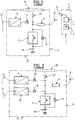
- the feeding of the embodiment of the figure 1 is not intended to be connected to a low voltage source, but only to a mains supply.
- the presentation first makes it possible to understand the other aspects of the invention before describing with reference to the figure 1 the embodiments of the other figures which include a possibility of connection to a low voltage source.
- the power supply 5 illustrated at figure 1 is intended to be used with a mobile phone 1.
- the mobile phone 1 can be of any known type. Classically, it is powered by a rechargeable battery 2 which is housed in its housing.
- the housing of the telephone 1 is generally provided with a connector 3 for recharging the battery 2 through a control circuit 4.
- the control circuit 4 serves in particular to check the charge level of the battery 2 to inform the user as well as the need or not to recharge the battery 2 and / or protect the battery 2 against misuse.
- Charging the battery 2 is performed by applying to the connector 3 a voltage of about 5 VDC which is provided in this case by the power supply 5 according to the invention.
- the power supply 5 comprises a converter circuit 6 which outputs a DC voltage of 6 volts from the sector applied to its input.
- the converter 6 can be of any suitable conventional type. In particular, it may be a conventional power supply circuit based on a transformer, a Graetz bridge and a filter capacitor. Nevertheless, it is preferable to use a switching power supply which has the advantage of being more compact and light.
- the converter 6 is preferably designed to accept as input the AC voltages of the existing power supplies in the different countries, in particular 110 volts 60 Hz and 220 to 240 volts, 50 Hz.
- the converter 6 can be implemented in the form of a switched-mode power supply automatically adapting as input to an entire range of AC or DC voltages covering the different mains supply voltages existing in the world.
- the converter 6 may be provided to receive as input any voltage in the range of 80 to 240 volts AC - 50 or 60 Hz - or in a range of 100 to 350 volts DC.
- the input of the converter 6 can be conventionally connected to the mains by means of a cord 7 provided at its end with a plug.
- the power supply 5 comprises a rechargeable battery 10.
- the output of the converter 6 is connected to the battery 10 to recharge it when the power supply 5 is connected to the mains.
- the converter 6 is preferably provided to carry out an ultrafast charge of the battery 10.
- the battery 10 is therefore chosen to tolerate such an ultrafast load and the converter 6 is designed to deliver a current sufficient to allow this charge.
- Such batteries particularly of the nickel-cadmium type in sealed cylindrical form, are for example marketed by the French company Saft.
- a circuit 11 controls the charging current applied to the battery 10.
- the control circuit 11 has been represented symbolically in the form of a controlled switch. In practice, this control circuit 11 can be implemented in a known manner, in particular by following the instructions of the battery manufacturer. It may in particular be based on a MOS transistor used in switching.
- the ultra-fast charge is to apply a constant high current until the voltage across the battery - or each of its cells - reaches a predefined threshold, which generally allows the battery to be recharged at about 75% of the battery. his ability, see more. The charge can then be continued slower at lower currents. Generally, it is It is also desirable to monitor the charging current of the battery according to the temperature of the battery. This role can also be provided by the circuit 11.
- the battery 10 is connected to a cord 8 provided at its end with a connector for connecting the power supply 5 to the connector 3 of the mobile telephone 1.
- the load control circuit 11 can be bridged by a diode 12.
- the diode 12 is preferably a Shottky diode because of the low voltage drop present at its terminals when it is conducting.
- the battery 10 thus makes it possible to recharge the battery of the telephone 1 and / or to directly feed the telephone 1.
- the control circuit 11 is based on a bidirectional switch, the role of the diode 12 can also be assumed by the switch of the control circuit 11 in which case the diode 12 is superfluous.
- the power supply 5 preferably comprises a circuit 9 limiting the current supplied by the battery 10 to the telephone 1.
- the current limiting circuit 9 serves to protect the mobile phone 1 against overcurrents that could damage it - this is especially the case when charging of the battery 2 by the power supply 5 - because the control circuit 4 of the telephone 1 does not generally provide this function or insufficiently.
- the current limiting circuit 9 may consist of a simple resistor. But it can also be a controlled switch - such as a MOS transistor - chopping the current as a function of the evolution of the charging current supplied to the battery 2.
- the choice of the battery 10 with regard to its storage capacity is made in consideration of the energy consumption of the device to be powered, in this case, in consideration of the capacity of the telephone battery 1.
- the a storage capacity of the battery 10 sufficient to completely charge the battery 2 or at least 90% is chosen.
- the storage capacity is preferably chosen at least equal to that of the battery 2.
- it can also be significantly greater than that of the battery of the device to be recharged to allow several charges of the latter.
- the choice is also made in consideration of the weight and the size of the battery 10, as well as the converter 6 which must provide a charging current which is all the more important in the case of ultra-fast charging of the battery 10.
- the choice of the battery 10 with respect to its voltage is made in consideration of the supply voltage required by the device to be powered.
- the voltage across it varies between 2.5 and 4.2 volts depending on its level of charge. Therefore, the voltage of the battery 10 is preferably chosen to be sufficient to charge the battery 2 up to 4.2 volts, given the voltage drops introduced by the intermediate elements between the battery 10 and the battery 2, that is to say in particular the diode 12, the circuit current limiter 9 and the control circuit 4.
- a nickel-cadnium battery of 6 volts - that is to say five cells of 0.9 volts each - whose voltage varies from 4.5 Volts at about 7.5 Volts depending on its charge level.
- the converter 6 is preferably chosen to provide a voltage sufficient to fully charge the battery 10.
- the voltage delivered by the converter 6 can be of the order of 8 or 9 volts.
- the power supply 5 may include a circuit limiting the output voltage applied to the cord 8, this circuit can for example be based on a zener diode.
- the power supply 5 can be supplemented by a voltage booster circuit to raise the voltage supplied by the battery 10 at a sufficient level.
- the output of the converter 6 is connected to the cord 8, where appropriate through the current limiter circuit 9 and / or the aforementioned voltage limiter circuit.
- the converter 6 supplies the external device directly when it is connected to the mains. In this way, the converter 6 charges the battery 10 at the same time that it powers the external device. Nevertheless, this connection between the output of the converter 6 and the cord 8 can be omitted. In this case, the power supply can not supply power directly to the device 1.
- a diode 13 is preferably provided at the output of the converter 6 to avoid the possible discharge of the battery 10 and / or the battery 2 of the outdoor unit, through the converter 6.
- the power supply 5 advantageously makes it possible to charge its battery 10 in a few minutes when the user has access to the sector. Optionally, it simultaneously allows to start charging the battery 2 of the phone 1 from the mains. When the sector is no longer available, the power supply 5 starts or continues charging the battery 2 from the energy stored in its battery 10.
- the diet of the figure 2 is a more developed version of the diet 5 of the figure 1 . It comprises identically, and with the same operation, all the elements of the power supply 5 which are therefore designated by the same references on the figure 2 .
- the power supply 15 is also intended to be used with the telephone 1 not shown on the figure 2 . It also includes additional circuits.
- the power supply 15 comprises a second converter 16 outputting the same voltage as the first converter 6, but from a low voltage applied at the input. It is preferably a converter accepting input voltage in a range of 3 to 15 volts, or 3 to 25 volts, continuous or alternative.
- This converter can be of any known type suitable. This may include a so-called "buck-boost" structure that lowers or raises the input voltage to provide a predetermined output voltage.
- the output of the converter 16 supplies the battery 10 and preferably also the external device, similarly to the converter 6.
- the output of the converter 16 can charge the battery 10 via the charge control circuit 11 and feed the external device connected to the cord 8 via, if appropriate, the current limiter circuit 9 and the voltage limiter circuit mentioned above for the power supply 5.
- the input of the converter is connected to a cord 17 provided with one or more connectors for connection with different types of low voltage electrical sources.
- a cord 17 provided with one or more connectors for connection with different types of low voltage electrical sources.
- low-voltage electrical energy sources can charge the battery 10 and / or directly power the outdoor unit, similar to the converter 6 from the mains.
- a diode 18 is preferably provided at the output of the converter 16 to prevent the batteries 2 or 10 can not be discharged through the converter 16 or that the converter 6 can inject a current therein. Similarly, the diode 13 prevents the converter 16 from injecting a current into the output of the converter 6.
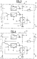
- the diet of the figure 3 is a variant of the diet 15 of the figure 2 . It comprises identically, and with the same operation, all the elements of the power supply 15 which are therefore designated by the same references on the figure 3 .
- the power supply 25 is also intended to be used with the telephone 1 not shown on the figure 3 .
- the power supply 25 differs from the power supply 15 in that it further comprises a controlled inverter switch 19 which can be implemented using transistors for example.
- This inverter 19 makes it possible to connect the input of the converter 16 selectively to the low-voltage power source connected to the cord 17 or the battery 10.
- the presence of the low voltage power source can be determined by the detection of its voltage at the terminals of the cord 17, for example using an amplifier amplifier operational circuit.
- the power supply is in the configuration of the power supply 15.
- the control circuit of the inverter 19 can cause the switching of the inverter 17 to connect the battery 10 to the input of the converter 16 In other words, the battery 10 then supplies the external device via the converter 16.
- This possibility is advantageous since the voltage across the battery 10 decreases progressively as a function of its discharge. Thus, it makes it possible to raise the voltage of the battery 10 to a level sufficient to continue to power the external device in the case where the voltage across the battery 10 becomes too low. This possibility therefore makes it possible to take fuller advantage of the storage capacity of the battery 10.
- the latter may also consist of a smaller number of battery cells to define a battery having a lower voltage. This results in a gain in weight and size.
- the battery 10 may consist of four 1.2-volt nickel-cadmium cells, instead of five in the example cited for 5. This results in a 4.8 Volt battery whose voltage varies between 3.6 Volts and 6 Volts depending on its level of charge. When it drops below 5 volts, the voltage of the battery 10 becomes insufficient to charge the battery 2 at a voltage of 4.2 volts taking into account the voltage drops introduced by the intermediate elements: diode 12, current limiting circuit 9, control circuit 4, etc ...
- the control circuit of the inverter 19 can be provided to connect the battery 10 to the input of the converter 16 as soon as the voltage of the battery 10 passes below 5 volts. Therefore, it is the output voltage - higher - of the converter 16 which supplies the battery 2. Moreover, the output voltage supplied by the converters 6 and 16 can be of the order of 6 or 7 volts, at the place of the aforementioned 8 or 9 volts in the case of power supply 5.
- the food 35 of the figure 4 is a variant of the diet 25 of the figure 3 . It comprises identically, and with the same operation, all the elements of the power supply 25 which are therefore designated by the same references on the figure 3 . In our example, the power supply 25 is also intended to be used with the telephone 1 not shown on the figure 4 .
- the power supply 35 differs from the power supply 25 in that it further comprises another controlled inverter switch 20 which can be implemented by means of transistors for example.
- This inverter 20 connects the low voltage power source connected to the cord 17 selectively to the input of the converter 16 via, if necessary, the inverter 19 or the cord 8 via, if appropriate, the current limiting circuit 9.
- the power supply 35 In the first position of the inverter 20, the power supply 35 is found in the configurations described above . In the other position, the low voltage power source supplies the external device via the current limiting circuit 9 and the battery 10, without passing through the converter 16.
- a control circuit - not shown - sets the inverter 20 in this other position when the voltage of the power source connected to the cord 17 is within an acceptable range to be applied directly to the external device and to the battery 10. This will avoid the loss of efficiency associated with the converter 16.
- this voltage range can be 5.5 to 7 volts.
- this variant can also be implemented in the absence of the inverter 19 for connecting the battery 10 to the input of the converter 16. In other words, this variant can be implemented on the power supply. 15 of the figure 2 . It suffices for this to connect the terminal of the switch 20 - which is connected to the figure 4 at one of the terminals of the inverter 19 - directly at the input of the converter 16.
- the power supply is provided to not charge the battery 10 , but only to power the external device, when the power supply is connected not to the mains by the cord 7, but only to a low-voltage energy source of less than 12 volts by the cord 17.
- the power supply when is optionally connected to a low voltage power source greater than or equal to 12 Volts or to the mains, the power supply preferably simultaneously ensures the charge of the battery 10 and the power supply of the external device connected to the cord 8 like this has been described previously. Nevertheless, when the external device is not connected to the cord 8, the power supply charges the battery 10 whatever the source of energy available at the input. If the current is not sufficient to allow ultra-fast charging, it can of course be realized more slowly.
- a power source having a voltage greater than or equal to 12 Volts generally corresponds to a motor vehicle battery which is capable of supplying a sufficient current to simultaneously charge the battery 10 and power the external device.
- a power source having a voltage of less than 12 volts generally corresponds to a source of low power which is then more advantageously to be used for the sole power supply of the external device. when it is connected to the cord 8.
- the low voltage source is a bicycle dynamo or a standard battery type R61 9 Volts, R12 4.5 Volts or similar.
- this variant is all the more justified by the fact that these batteries are themselves an energy storage element easily transportable by an individual: it is then more advantageous to directly power the outdoor device without intermediate storage in the battery 10 which necessarily implies yield losses as well as time.
- the power supply may include a manual switch allowing the user selectively to allow or prevent charging of the battery 10 from the input power source. Therefore, it can choose itself whether it wishes to power only the external device connected to the power supply or to simultaneously charge the battery 10.
- the power supplies 5, 15, 25 and 35 may all comprise a housing 23 which houses all of the circuits forming part of it, including the battery 10, with the plugs of the cords 7, 8 and, where appropriate, 17, which are accessible from outside the housing 23.
- the housing 23 has been represented symbolically in phantom in the figures.
- the battery 10 may be external to the housing 23 and removable.
- the power supply may comprise a connector - for example placed in a housing made in the housing 23 and accessible from outside the housing - to enable the battery 10 to be connected and disconnected. This variant has the advantage of being able to charge successively several batteries 10 and then use them successively to power the external device.
- a separate cord - including, if necessary, a current limiting circuit similar to that referenced 9 - to connect the external device to the battery 10, without the intermediary of the 23.
- the power supply in the housing 23 is used to recharge the battery 10 which can then be separated from the housing 23 and connected with the separate cord to the external device to power it.
- the cord 8 of the power supply in the housing 23 can even be removed in this case.
- the battery 10 can be replaced by any appropriate electrical energy storage means, preferably accepting to be loaded ultra-fast.
- This may include supercapacitors. It can be by example of supercapacitors with capacities of 3000 Farad marketed by the Korean company Ness.
- the invention can be implemented with a battery 10 or other electrical energy storage means not allowing an ultrafast load in which case the power supply of the invention may not be provided to be able to achieve this. type of charge.
- Another variant is to provide a solar panel 21 - for example 7.2 volts - on the housing 23 and which also charges the battery 10 and / or power the outdoor unit.
- a diode 22 can also be provided to prevent the battery 10, the battery 2 or other power source connected to the input of the power supply can be discharged into the solar panel.
- Such a solar panel can advantageously provide electrical energy in the absence of any other available source.
- cords with plugs 7, 8 and 17 can be replaced by any other suitable means for connecting the input power sources, as well as the external device.
- the battery 10 generally consists of several elementary accumulator cells connected in series to obtain the desired battery voltage - cf. examples cited in relation to the figures 1 and 3 . Therefore, the charging of the battery 10 is carried out conventionally on the battery 10 with its cells connected in series. As a variant, the charge of the battery 10 can be carried out individually for each of the cells of the battery 10. Such a variant is represented by the figure 5 and is based on the diet 5 of the figure 2 .
- the references 8 and 9 respectively denote the current limiting circuit and the cord used to connect the external device to be powered.
- the exemplary battery 10 comprises four elementary cells 10a-10d. Each cell 10a-10d corresponds to a charge control circuit 11a-11d.
- each of the load control circuits 11a-11d is to carry out an ultrafast load of the corresponding cell.
- the current is provided by a converter 6a which replaces the converter 6 of the power supply 2.
- the converter 6a differs from the converter 6 in that it delivers an adequate voltage to charge a cell of the battery, and not the battery as a whole .
- the load control circuits 11a-11d are similar to the control circuit 11 of the power supply 5, except for what they are each provided for the control of a single battery cell, instead of the entire battery.
- a series of controlled switches 27a-27c - for example MOS transistors - allow - when they are closed - to connect the cells in series so as to constitute the battery 10.
- Another series of switches Controlled 26a-26c - for example MOS transistors - allow - when closed - to connect a terminal of each battery cell - except the last referenced 10d - to ground, the other terminal of the cells being connected permanently to their respective load control circuit 11a-11d.
- the cell 10d is permanently connected to the ground.
- the terminal of the first cell 10a which is connected to its load control circuit 11a is also connected to the cord 8 via the current limiting circuit 9.
- a control circuit - not shown - opens the switches 27a-27c and close the switches 26a-26c. In this way, each of the cells 10a-10c is loaded through its load control circuit 11a-11c. On the contrary, when it comes to powering the external device connected to the cord 8, the control circuit opens the switches 26a-26c and close the switches 27a-27c. The voltage resulting from the series setting of the cells 10a-10d is then applied to the apparatus by means of the diode 13c and the current limiting circuit 9.
- the supply can be provided with an additional converter 6b if It is desired to be able to simultaneously charge the cells 10a-10d and supply the device connected to the cord 8 when the cord 7 is connected to the mains.
- the converter 6b also receives the input sector through the cord 7.
- the converter 6b provides a voltage output to directly power the device via the current limiting circuit 9.
- a diode 13b provides the coupling to the limiting circuit.
- the device according to the invention makes it possible to supply any kind of electrical appliance, in particular appliances that do not have a clean battery, unlike the mobile phone used as an example.
- the mobile phone used as an example can power a radio.
- the charge control circuit 11 and the battery 10 are eliminated in the power supplies 15 and 35. This simply results in a universal power supply allowing the power supply of the external device to be selected by the sector or by a low-voltage energy source, see by the solar panel 21 integrated in the housing 23. But the power supply no longer offers the possibility of clean storage of electrical energy.
- its weight is preferably less than or equal to three times, more preferably to one and a half times and even more preferably to one time the weight of the device that is intended to feed in the case where this device is a mobile phone or a pocket electronic diary.
- its weight is preferably less than or equal to 20%, more preferably 10% of the weight of the apparatus that it is intended to supply in the case where this device is a laptop.
- FIG. 1 illustrates the fact that the use of a buffer energy storage means 10 is independent of the possibility for the device of the invention to be powered from a mains supply or from a source of electrical energy low tension.
Description
La présente invention concerne un dispositif d'alimentation électrique portable, permettant notamment d'alimenter un appareil tel qu'un téléphone portable. Le document
Pour pallier cet inconvénient, il est proposé avec certains appareils un cordon permettant de le brancher sur une prise allume-cigare d'un véhicule automobile, ce qui permet de l'alimenter à partir de la batterie du véhicule. Mais l'utilisateur n'a pas toujours son véhicule à disposition ou encore pas toujours suffisamment longtemps pour recharger la batterie de son appareil.To overcome this drawback, it is proposed with some devices a cord for connecting it to a cigarette lighter socket of a motor vehicle, which allows to feed it from the vehicle battery. But the user does not always have his vehicle available or still not long enough to recharge the battery of his device.
L'invention vise à pallier au moins partiellement les inconvénients de l'art antérieur.The invention aims to at least partially overcome the disadvantages of the prior art.
Ainsi, un premier but de l'invention est de faciliter l'alimentation ou la recharge d'un appareil électrique en présence de sources d'énergie électrique différentes.Thus, a first object of the invention is to facilitate the supply or charging of an electrical appliance in the presence of different electrical energy sources.
Un autre but de l'invention est de prolonger l'autonomie d'appareils électriques incorporant une batterie d'alimentation rechargeable.Another object of the invention is to extend the autonomy of electrical appliances incorporating a rechargeable battery pack.
Encore un autre but de l'invention est de conférer une autonomie satisfaisante à de tels appareils malgré des temps de disponibilité limités de l'alimentation secteur ou autre.Yet another object of the invention is to provide a satisfactory autonomy to such devices despite limited availability of mains power or other times.
Pour atteindre ce premier but, l'invention propose un dispositif d'alimentation électrique portable selon la revendication 1. Il comprend:
- un moyen de connexion permettant de brancher un appareil à alimenter ; et
- un circuit d'alimentation fournissant en sortie une tension d'alimentation pour l'appareil lorsque le circuit est branché au choix à une alimentation secteur ou à une source d'énergie électrique basse tension.
- connection means for connecting a device to power; and
- a supply circuit supplying a supply voltage for the apparatus when the circuit is connected to a mains power supply or to a low-voltage electrical energy source.
Dans le cadre de l'invention, l'on entend par basse tension une tension inférieure ou égale à de préférence 60 Volts, plus avantageusement à 40 Volts, voire 28 Volts.In the context of the invention, low voltage means a voltage less than or equal to preferably 60 volts, more preferably 40 volts or 28 volts.
Le dispositif est de préférence prévu pour accepter en entrée une basse tension quelconque comprise dans une plage allant par exemple de 3 à 60 Volts. En variante, il peut être prévu pour une ou plusieurs basses tensions prédéfinies telles que 6 Volts, 12 Volts et 24 Volts.The device is preferably designed to accept as input any low voltage in a range for example from 3 to 60 volts. Alternatively, it may be provided for one or more pre-defined low voltages such as 6 volts, 12 volts and 24 volts.
L'invention est tout particulièrement adaptée pour l'alimentation d'appareil présentant une entrée d'alimentation basse tension, par exemple 6 Volts, 9Volts ou 12 Volts. L'on comprendra que dans le cadre de l'invention, l'entrée d'alimentation de l'appareil peut servir selon l'appareil :
- à alimenter directement l'appareil pour le faire fonctionner - c'est-à-dire sans utiliser sa batterie d'alimentation comme tampon -, mais non pas à recharger sa batterie d'alimentation ; ou
- à recharger sa batterie d'alimentation, mais non pas à alimenter directement l'appareil pour le faire fonctionner ; ou
- à la fois à alimenter directement l'appareil pour le faire fonctionner et à recharger sa batterie d'alimentation.
- powering the device directly to operate it - that is, without using its battery pack as a buffer - but not to recharge its battery pack; or
- to recharge its battery pack, but not to directly power the device to operate it; or
- both to directly power the device to operate it and recharge its battery pack.
Dans le cas où le dispositif est utilisé uniquement pour recharger la batterie d'alimentation d'un appareil, la batterie peut être chargée par le dispositif que la batterie soit dans l'appareil ou que la batterie ait été préalablement retirée de l'appareil pour l'opération de charge.In the case where the device is used solely to recharge the battery pack of a device, the battery may be charged by the device whether the battery is in the device or the battery has been previously removed from the device for the charging operation.
Selon un mode de réalisation préféré, le circuit comprend un convertisseur de tension fournissant en sortie une tension donnée servant à alimenter l'appareil, lorsque le circuit est branché à une source d'énergie électrique basse tension. Mais si le circuit est branché à une source d'énergie électrique basse tension présentant une tension comprise dans une plage de tensions prédéterminée incluant la tension que fournit en sortie le convertisseur, alors le circuit alimente l'appareil branché au moyen de connexion à partir de la source d'énergie électrique sans l'intermédiaire du convertisseur.According to a preferred embodiment, the circuit comprises a voltage converter outputting a given voltage used to power the apparatus, when the circuit is connected to a low-voltage electrical energy source. But if the circuit is connected to a low-voltage electrical power source having a voltage within a predetermined voltage range including the voltage output of the converter, then the circuit supplies the device connected to the connection means from the source of electrical energy without the intermediary of the converter.
Selon l'invention le dispositif comprend un moyen de stockage d'énergie électrique rechargeable et dans lequel :
- le circuit charge le moyen de stockage d'énergie lorsque le circuit est branché à une source d'énergie électrique appropriée ; et
- le moyen de connexion permet d'alimenter l'appareil à partir du moyen de stockage d'énergie.
- the circuit charges the energy storage means when the circuit is connected to a suitable power source; and
- the connection means is used to power the apparatus from the energy storage means.
Ainsi, le dispositif permet d'alimenter l'appareil grâce au moyen de stockage chargé au moins partiellement, même si le circuit chargeur n'est plus branché à la source d'énergie électrique servant à le charger. La capacité du moyen de stockage est choisie pour pouvoir alimenter l'appareil de préférence pendant au moins une demi-heure, mais plus avantageusement pendant au moins une heure, voir deux heures. Lorsque le dispositif est utilisé pour recharger la batterie d'un appareil, il est avantageux que la capacité du moyen de stockage soit au moins égale à la capacité de stockage de la batterie de l'appareil, ou tout au moins la moitié de cette dernière.Thus, the device provides power to the device through the storage means loaded at least partially, even if the charger circuit is no longer connected to the source of electrical energy for charging. The capacity of the storage means is chosen to be able to feed the apparatus preferably for at least half an hour, but more advantageously for at least one hour, see two hours. When the device is used to recharge the battery of a device, it is advantageous that the capacity of the storage means is at least equal to the storage capacity of the battery of the device, or at least half of the latter .
De façon avantageuse, le circuit peut charger de façon ultrarapide le moyen de stockage d'énergie lorsque le circuit est branché à une source d'énergie électrique appropriée. Dans le cadre de l'invention, la charge ultrarapide du moyen de stockage correspond à la charge électrique du moyen de stockage à au moins 50% de sa capacité de stockage effectuée en moins d'une demi-heure, de préférence en moins d'un quart d'heure et plus avantageusement en moins de 8 minutes. Le dispositif permet ainsi des recharges rapides de son moyen de stockage même lorsque la source d'énergie électrique n'est disponible que quelques minutes tel que par exemple un homme d'affaire de passage dans sa chambre d'hôtel pendant quelques minutes entre deux rendez-vous à l'extérieur. Le dispositif permet d'alimenter l'appareil par la suite en l'absence de toute autre source d'énergie. Etant donné qu'il est de type portable, l'utilisateur peut emmener le dispositif avec lui pour alimenter son appareil dans n'importe quel lieu. Ce mode de réalisation est d'autant plus avantageux lorsque la batterie d'alimentation de l'appareil et/ou l'appareil lui-même ne sont pas conçus pour permettre une charge ultrarapide de cette batterie. En effet, le moyen de stockage procure une autonomie importante comparativement à la batterie d'alimentation de l'appareil, lorsque le temps de charge est limité par les circonstances. Très généralement, les appareils incorporant une batterie d'alimentation - tels que téléphones ou ordinateurs portables - n'autorisent pas une recharge ultrarapide de celle-ci. En effet, ni les circuits de l'appareil, ni la batterie elle-même ne supportent les courants élevés - généralement plusieurs ampères - nécessaires à une telle charge ultrarapide. Ces appareils nécessitent généralement au moins une heure, et bien souvent au moins trois heures, sinon plus, pour recharger leur batterie.Advantageously, the circuit can super-fast charge the energy storage means when the circuit is connected to a suitable power source. In the context of the invention, the ultrafast charge of the storage means corresponds to the electrical charge of the storage means to at least 50% of its storage capacity carried out in less than half an hour, preferably in less than a quarter of an hour and more advantageously in less than 8 minutes. The device thus allows rapid refills of its storage means even when the power source is available for a few minutes such as for example a businessman passing through his hotel room for a few minutes between two appointments outside. The device allows to feed the device thereafter in the absence of any other source of energy. Since it is portable, the user can take the device with him to power his device in any place. This embodiment is all the more advantageous when the battery pack of the device and / or the device itself are not designed to allow ultra-fast charging of this battery. Indeed, the storage means provides a significant autonomy compared to the battery pack of the device, when the charging time is limited by the circumstances. Most commonly, devices incorporating a battery pack - such as phones or laptops - do not allow ultra-fast charging of the battery. Indeed, neither the circuits of the device nor the battery itself can withstand the high currents - usually several amperes - required for such an ultrafast load. These devices usually require at least an hour, and often at least three hours, if not more, to recharge their battery.
Le moyen de stockage d'énergie électrique peut comprendre une batterie rechargeable. Dans ce cas, la capacité de la batterie rechargeable est inférieure ou égale de préférence à trois fois, plus avantageusement à deux fois, voire à une fois et demi la capacité de stockage de la batterie de l'appareil, ce qui permet une compacité et un poids limité du dispositif améliorant ainsi sa portabilité.The electrical energy storage means may comprise a rechargeable battery. In this case, the capacity of the rechargeable battery is less than or equal to preferably three times, more preferably twice, or even once and half the storage capacity of the battery of the device, which allows compactness and a limited weight of the device thus improving its portability.
Selon un mode de réalisation avantageux, le moyen de stockage d'énergie électrique comprend une batterie rechargeable et cette dernière comprend plusieurs cellules accumulatrices branchées en série lorsque la batterie alimente l'appareil branché au moyen de connexion, chaque cellule de la batterie étant chargée de façon ultrarapide à travers un circuit de contrôle de charge respectif.According to an advantageous embodiment, the electrical energy storage means comprises a rechargeable battery and the latter comprises several accumulator cells connected in series when the battery supplies the connected device to the connection means, each cell of the battery being charged with ultrafast way through a respective load control circuit.
Selon un autre mode de réalisation préféré, le circuit comprend un convertisseur de tension fournissant en sortie une tension donnée servant à la charge - éventuellement ultrarapide - du moyen de stockage d'énergie, lorsque le circuit est branché à une source d'énergie électrique basse tension, et le moyen de stockage d'énergie alimente l'appareil branché au moyen de connexion par l'intermédiaire du convertisseur fonctionnant en élévateur de tension lorsque la tension aux bornes du moyen de stockage d'énergie est inférieure à un seuil prédéterminé.According to another preferred embodiment, the circuit comprises a voltage converter supplying at output a given voltage used for charging - possibly ultrafast - energy storage means, when the circuit is connected to a source of low electrical energy voltage, and the energy storage means supplies the device connected to the connection means through the converter operating voltage booster when the voltage across the energy storage means is below a predetermined threshold.
De plus, il peut être prévu que lorsque le circuit est branché à une source d'énergie électrique basse tension présentant une tension comprise dans une plage de tensions prédéterminée incluant la tension que fournie en sortie le convertisseur, le circuit alimente l'appareil branché au moyen de connexion, et/ou charge le moyen de stockage d'énergie, à partir de la source d'énergie électrique sans l'intermédiaire du convertisseur.In addition, it can be provided that when the circuit is connected to a low-voltage electrical power source having a voltage within a predetermined voltage range including the voltage outputted from the converter, the circuit supplies power to the connected device. connecting means, and / or loads the energy storage means, from the source of electrical energy without the intermediary of the converter.
Selon encore un autre mode de réalisation préféré, le circuit comprend un convertisseur de tension fournissant en sortie une tension donnée servant à la charge du moyen de stockage d'énergie et/ou à alimenter l'appareil branché au moyen de connexion, lorsque le circuit est branché à une source d'énergie électrique basse tension. Mais lorsque le circuit est branché à une source d'énergie électrique basse tension présentant une tension comprise dans une plage de tensions prédéterminée incluant la tension que fournit en sortie le convertisseur, alors le circuit alimente l'appareil branché au moyen de connexion et/ou charge le moyen de stockage d'énergie, à partir de la source d'énergie électrique sans l'intermédiaire du convertisseur.According to yet another preferred embodiment, the circuit comprises a voltage converter outputting a given voltage for charging the energy storage means and / or supplying the device connected to the connection means, when the circuit is connected to a low voltage power source. But when the circuit is connected to a low-voltage electrical power source having a voltage within a predetermined voltage range including the voltage output of the converter, then the circuit supplies the device connected to the connection means and / or charges the energy storage means, from the source of electrical energy without the intermediary of the converter.
Selon l'invention lorsque le circuit est branché à une source d'énergie électrique présentant une tension inférieure à un seuil prédéterminé, le circuit alimente l'appareil branché au moyen de connexion, mais ne charge pas le moyen de stockage d'énergie.According to the invention when the circuit is connected to a source of electrical energy having a voltage below a predetermined threshold, the circuit supplies the device connected to the connection means, but does not charge the energy storage means.
Par ailleurs, le dispositif peut avantageusement comprendre un circuit limitant le courant fourni à l'appareil.Furthermore, the device may advantageously comprise a circuit limiting the current supplied to the device.
Le dispositif peut comprendre en outre un panneau solaire permettant d'alimenter l'appareil et/ou charger le moyen de stockage d'énergie.The device may further include a solar panel for powering the apparatus and / or charging the energy storage means.
Selon un autre mode de réalisation préféré, le dispositif comprend des moyens de connexion pour connecter un moyen de stockage d'énergie électrique amovible et portable dans lequel, lorsque ledit moyen de stockage d'énergie électrique amovible est connecté aux dits moyens de connexion, le circuit d'alimentation charge de façon ultrarapide le moyen de stockage d'énergie amovible lorsque le circuit d'alimentation est branché à une source d'énergie électrique appropriée. Dans ce cas, le dispositif peut comprendre ou non un autre moyen de stockage non amovible tel que décrit précédemment. Le moyen de stockage d'énergie amovible peut comprendre une batterie rechargeable. Le moyen de stockage amovible ainsi chargé peut être débranché du dispositif et permet ensuite d'alimenter un appareil - par exemple pour recharger la batterie de l'appareil s'il en dispose - en l'absence de toute autre source d'énergie. Etant donné qu'il est de type portable, l'utilisateur peut emmener le moyen de stockage amovible avec lui pour alimenter son appareil dans n'importe quel lieu. Les indications préférentielles concernant le choix de la capacité du moyen de stockage d'énergie du dispositif données plus haut s'appliquent également au moyen de stockage amovible.According to another preferred embodiment, the device comprises connection means for connecting a removable and portable electrical energy storage means in which, when said removable electrical energy storage means is connected to said connection means, the The power supply circuit charges the detachable energy storage means rapidly when the supply circuit is connected to a suitable power source. In this case, the device may or may not include another non-removable storage means as described above. The removable energy storage means may include a rechargeable battery. The removable storage means thus charged can be disconnected from the device and can then power a device - for example to recharge the battery of the device if it has - in the absence of any other source of energy. Since it is portable, the user can take the removable storage means with him to power his device in any place. The preferred indications concerning the choice of the capacity of the energy storage means of the device given above also apply to the means of removable storage.
L'invention propose aussi l'utilisation du dispositif de l'invention pour alimenter un appareil électrique. L'appareil est de préférence de type portable, avantageusement un téléphone portable ou un ordinateur portable ou un agenda électronique de poche. Une utilisation avantageuse réside dans le fait que le dispositif de l'invention recharge une batterie d'alimentation (2) de l'appareil électrique.The invention also proposes the use of the device of the invention for powering an electrical appliance. The device is preferably portable type, preferably a mobile phone or a laptop or a pocket diary. An advantageous use lies in the fact that the device of the invention recharges a battery pack (2) of the electrical apparatus.
Par ailleurs, l'on comprendra que la charge d'un moyen de stockage d'énergie de l'invention peut être mise en oeuvre indépendamment du fait que le dispositif de l'invention puisse être branché en entrée au choix à une alimentation secteur et à une source d'énergie électrique basse tension.Furthermore, it will be understood that the load of an energy storage means of the invention can be implemented independently of the fact that the device of the invention can be optionally connected to a mains power supply and to a source of low voltage electrical energy.
L'invention permet de recharger le moyen de stockage dans des situations où la source d'énergie électrique est disponible peu de temps, par exemple, un homme d'affaire de passage dans sa chambre d'hôtel pendant quelques minutes entre deux rendez-vous à l'extérieur. Le moyen de stockage ainsi chargé permet ensuite d'alimenter son appareil en l'absence de toute autre source d'énergie. Etant donné qu'il est de type portable, l'utilisateur peut emmener le moyen de stockage avec lui pour alimenter son appareil dans n'importe quel lieu. L'invention est tout particulièrement adaptée pour l'alimentation d'appareil présentant une entrée d'alimentation basse tension, par exemple 6 Volts, 9Volts ou 12 Volts.The invention makes it possible to recharge the storage means in situations where the source of electric power is available for a short time, for example, a businessman passing through his hotel room for a few minutes between two appointments. outside. The storage means thus charged then allows to power its device in the absence of any other source of energy. Since it is portable, the user can take the storage means with him to power his device in any place. The invention is particularly suitable for the supply of apparatus having a low voltage supply input, for example 6 volts, 9 volts or 12 volts.
L'invention est d'autant plus avantageuse lorsque la batterie d'alimentation de l'appareil et/ou l'appareil lui-même ne sont pas conçus pour permettre une charge ultrarapide de cette batterie. En effet, le moyen de stockage procure une autonomie importante comparativement à la batterie d'alimentation de l'appareil, lorsque le temps de charge est limité par les circonstances. Très généralement, les appareils incorporant une batterie d'alimentation - tels que téléphones ou ordinateurs portables - n'autorisent pas une recharge ultrarapide de celle-ci. En effet, ni les circuits de l'appareil, ni la batterie elle-même ne supportent les courants élevés - généralement plusieurs ampères - nécessaires à une telle charge ultrarapide. Ces appareils nécessitent généralement au moins une heure, et bien souvent au moins trois heures, sinon plus, pour recharger leur batterie.The invention is all the more advantageous when the battery pack of the device and / or the device itself are not designed to allow ultra-fast charging of this battery. Indeed, the storage means provides a significant autonomy compared to the battery pack of the device, when the charging time is limited by the circumstances. Most commonly, devices incorporating a battery pack - such as phones or laptops - do not allow ultra-fast charging of the battery. Indeed, neither the circuits of the device nor the battery itself can withstand the high currents - usually several amperes - required for such an ultrafast load. These devices usually require at least an hour, and often at least three hours, if not more, to recharge their battery.
L'on comprendra que dans le cadre de l'invention, l'entrée d'alimentation de l'appareil peut servir selon l'appareil :
- à alimenter directement l'appareil pour le faire fonctionner - c'est-à-dire sans utiliser sa batterie d'alimentation comme tampon -, mais non pas à recharger sa batterie d'alimentation ; ou
- à recharger sa batterie d'alimentation, mais non pas à alimenter directement l'appareil pour le faire fonctionner ; ou
- à la fois à alimenter directement l'appareil pour le faire fonctionner et à recharger sa batterie d'alimentation.
- powering the device directly to operate it - that is, without using its battery pack as a buffer - but not to recharge its battery pack; or
- to recharge its battery pack, but not to directly power the device to operate it; or
- both to directly power the device to operate it and recharge its battery pack.
Ainsi, suivant un mode de réalisation préféré de l'invention, dans l'étape b), le moyen de stockage d'énergie peut servir à recharger la batterie d'alimentation de l'appareil. Dans ce cas, il est avantageux que la capacité du moyen de stockage soit au moins égale à la capacité de stockage de la batterie de l'appareil, ou tout au moins la moitié de cette dernière. Le moyen de stockage permet alors de recharger de façon sensible la batterie de l'appareil. Dans ce cas, la capacité du moyen de stockage surtout s'il comprend une batterie rechargeable, est inférieure ou égale de préférence à trois fois, plus avantageusement à deux fois, voire à une fois et demi la capacité de stockage de la batterie de l'appareil, ce qui permet une compacité et un poids limité améliorant ainsi sa portabilité.Thus, according to a preferred embodiment of the invention, in step b), the energy storage means can be used to recharge the power supply battery. the device. In this case, it is advantageous that the capacity of the storage means is at least equal to the storage capacity of the battery of the device, or at least half of the latter. The storage means then reloads significantly the battery of the device. In this case, the capacity of the storage means, especially if it comprises a rechargeable battery, is less than or equal to preferably three times, more advantageously twice or even one and a half times the storage capacity of the battery of the battery. the device, which allows a compactness and a limited weight thus improving its portability.
Ce mode de réalisation de l'invention est là encore particulièrement avantageux lorsque la batterie d'alimentation de l'appareil et/ou l'appareil lui-même ne sont pas conçus pour permettre une charge ultrarapide de sa batterie. Ce mode de réalisation permet une charge du moyen de stockage même si la source d'énergie électrique -par exemple le secteur ou une prise allume-cigare d'une voiture- est disponible que quelques minutes. Du fait qu'il est de type portable, l'utilisateur peut emmener le moyen de stockage avec lui pour recharger grâce à celui-ci la batterie de son appareil alors même qu'il n'a plus accès à la source d'énergie électrique.This embodiment of the invention is again particularly advantageous when the battery pack of the device and / or the device itself are not designed to allow ultra-fast charging of its battery. This embodiment allows charging of the storage means even if the source of electrical energy - for example the sector or a cigarette lighter socket of a car - is available only a few minutes. Because it is portable, the user can take the storage means with him to recharge the battery of his device thanks to it while he no longer has access to the source of electrical energy. .
Selon un autre mode de réalisation de l'invention, dans l'étape b), le moyen de stockage d'énergie est branché à l'entrée d'alimentation de l'appareil par l'intermédiaire d'un circuit limitant le courant fourni à l'appareil. Ce circuit limiteur protège notamment l'appareil contre des surintensités qui pourraient le détériorer.According to another embodiment of the invention, in step b), the energy storage means is connected to the power input of the apparatus via a circuit limiting the current supplied. the apparatus. This limiter circuit protects the device against overcurrents that could damage it.
Selon un autre mode de réalisation de l'invention, dans l'étape a), la charge du moyen de stockage d'énergie est effectuée à l'aide d'un chargeur prévu pour être branché au choix à une alimentation secteur ou à une source d'énergie électrique basse tension. Comme déjà indiqué, dans le cadre de l'invention, l'on entend par basse tension une tension inférieure ou égale à 60 Volts.According to another embodiment of the invention, in step a), the charging of the energy storage means is carried out using a charger intended to be connected optionally to a mains power supply or to a power supply. source of low voltage electrical energy. As already indicated, in the context of the invention, low voltage means a voltage less than or equal to 60 volts.
Selon encore un autre mode de réalisation de l'invention, dans l'étape a), la charge du moyen de stockage d'énergie est effectuée à l'aide d'un chargeur prévu également pour alimenter l'appareil. Il est ainsi possible de simultanément charger le moyen de stockage et d'alimenter l'appareil, ainsi que de charger la batterie de ce dernier le cas échéant.According to yet another embodiment of the invention, in step a), the charging of the energy storage means is carried out using a charger also provided for powering the apparatus. It is thus possible to simultaneously charge the storage means and to power the device, as well as to charge the battery of the latter if necessary.
Par ailleurs, l'appareil à alimenter est de préférence du type portable. Il peut s'agir avantageusement d'un téléphone portable ou d'un ordinateur portable ou d'un agenda électronique de poche.Moreover, the device to be powered is preferably of the portable type. It can be advantageously a mobile phone or a laptop or a pocket diary.
Selon un autre aspect, l'invention propose encore un dispositif d'alimentation électrique portable, comprenant :
- un moyen de stockage d'énergie électrique rechargeable ;
- un circuit chargeur chargeant de préférence de façon ultrarapide le moyen de stockage d'énergie lorsqu'il est branché à une source d'énergie électrique appropriée ; et
- un moyen de connexion permettant de brancher un appareil pour alimenter celui-ci à partir du moyen de stockage d'énergie.
- rechargeable electrical energy storage means;
- a charging circuit preferably super fast charging the energy storage means when connected to a suitable electrical power source; and
- connection means for connecting an apparatus for supplying the same from the energy storage means.
Le dispositif selon l'invention permet d'alimenter l'appareil grâce au moyen de stockage chargé au moins partiellement, même si le circuit chargeur n'est plus branché à la source d'énergie électrique servant à le charger. La capacité du moyen de stockage est choisie pour pouvoir alimenter l'appareil de préférence pendant au moins une demi-heure, mais plus avantageusement pendant au moins une heure, voir deux heures.The device according to the invention makes it possible to supply the device with the at least partially charged storage means, even if the charger circuit is no longer connected to the source of electrical energy used to charge it. The capacity of the storage means is chosen to be able to feed the apparatus preferably for at least half an hour, but more advantageously for at least one hour, see two hours.
Si la charge du moyen de stockage est de type ultrarapide, ce dispositif permet des recharges rapides de son moyen de stockage même lorsque la source d'énergie électrique n'est disponible que quelques minutes, le dispositif permettant d'alimenter l'appareil par la suite en l'absence de toute autre source d'énergie.If the load of the storage means is ultrafast type, this device allows rapid refills of its storage means even when the power source is available for a few minutes, the device for powering the device by the in the absence of any other source of energy.
Selon un mode de réalisation de l'invention, le moyen de stockage d'énergie électrique comprend une batterie rechargeable.According to one embodiment of the invention, the electrical energy storage means comprises a rechargeable battery.
Par ailleurs, la batterie peut comprendre plusieurs cellules accumulatrices branchées en série lorsque la batterie alimente l'appareil branché au moyen de connexion et chaque cellule peut avantageusement être chargée de façon ultrarapide à travers un circuit de contrôle de charge respectif.On the other hand, the battery may comprise a plurality of accumulator cells connected in series when the battery supplies the device connected to the connection means and each cell may advantageously be charged in a very fast manner through a respective charge control circuit.
Selon un autre mode de réalisation de l'invention, le circuit chargeur alimente l'appareil branché au moyen de connexion, lorsque le circuit chargeur est branché à la source d'énergie électrique.According to another embodiment of the invention, the charger circuit supplies the device connected to the connection means, when the charger circuit is connected to the source of electrical energy.
Selon encore un autre mode de réalisation de l'invention, le circuit chargeur est apte à être branché au choix à une alimentation secteur ou à une alimentation basse tension.According to yet another embodiment of the invention, the charger circuit is suitable for connection to a mains power supply or to a low voltage supply.
Selon encore un autre mode de réalisation de l'invention, le circuit chargeur comprend un convertisseur de tension fournissant en sortie une tension donnée servant à la charge ultrarapide du moyen de stockage d'énergie, lorsque le dispositif est branché à une source d'énergie électrique basse tension, et en ce que le moyen de stockage d'énergie alimente l'appareil branché au moyen de connexion par l'intermédiaire du convertisseur fonctionnant en élévateur de tension lorsque la tension aux bornes du moyen de stockage d'énergie est inférieure à un seuil prédéterminé.According to yet another embodiment of the invention, the charger circuit comprises a voltage converter outputting a given voltage for the ultra-fast charging of the energy storage means, when the device is connected to a power source. electrical low voltage, and in that the energy storage means supplies the device connected to the connection means through the converter operating voltage booster when the voltage across the energy storage means is less than a predetermined threshold.
Il est également avantageux que, lorsque le circuit chargeur est branché à une source d'énergie électrique basse tension présentant une tension comprise dans une plage de tensions prédéterminée incluant la tension que fournie en sortie le convertisseur, le circuit chargeur alimente l'appareil branché au moyen de connexion, et/ou charge le moyen de stockage d'énergie, à partir de la source d'énergie électrique sans l'intermédiaire du convertisseur. Suivant l'invention, lorsque le circuit chargeur est branché à une source d'énergie électrique présentant une tension inférieure à un seuil prédéterminé, le circuit chargeur alimente l'appareil branché au moyen de connexion, mais ne charge pas le moyen de stockage d'énergie. Suivant l'invention, lorsque le circuit est branché à une source d'énergie électrique présentant une tension supérieure ou égale audit seuil prédéterminé, le circuit alimente l'appareil branché au moyen de connexion et charge le moyen de stockage d'énergie. De façon générale, l'invention a pour avantage de ne pas exiger de modifications des appareils électriques à alimenter, en particulier de l'interface physique de connexion servant d'entrée d'alimentation des appareils. Dès lors, l'invention peut être mise en oeuvre pour tout appareil électrique existant.It is also advantageous that, when the charger circuit is connected to a low-voltage electrical power source having a voltage within a predetermined voltage range including the voltage output of the converter, the charger circuit supplies the device connected to the connection means, and / or loads the energy storage means, from the source of electrical energy without the intermediary of the converter. According to the invention, when the charger circuit is connected to a source of electrical energy having a voltage lower than a predetermined threshold, the charger circuit supplies the device connected to the connection means, but does not charge the storage means. energy. According to the invention, when the circuit is connected to a source of electrical energy having a voltage greater than or equal to said predetermined threshold, the circuit supplies the device connected to the connection means and charges the energy storage means. In general, the invention has the advantage of not requiring modifications of the electrical appliances to be powered, in particular the physical connection interface serving as the power input of the devices. Therefore, the invention can be implemented for any existing electrical device.
D'autres caractéristiques et avantages de l'invention apparaîtront à la lecture de la description qui suit de modes de réalisation préférés de l'invention, donnée à titre d'exemple et en référence au dessin annexé.
- La
figure 1 représente le schéma de principe d'une alimentation selon l'invention, prévue pour recharger la batterie d'un téléphone portable. - La
figure 2 représente une variante de l'alimentation de lafigure 1 . - La
figure 3 représente une variante de l'alimentation de lafigure 2 . - La
figure 4 représente une variante de l'alimentation de lafigure 3 . - La
figure 5 représente une variante de l'alimentation de lafigure 2 qui permet un contrôle individuel de la charge de chaque cellule accumulatrice constituant la batterie équipant cette alimentation.
- The
figure 1 represents the block diagram of a power supply according to the invention, designed to recharge the battery of a mobile phone. - The
figure 2 represents a variant of the diet of thefigure 1 . - The
figure 3 represents a variant of the diet of thefigure 2 . - The
figure 4 represents a variant of the diet of thefigure 3 . - The
figure 5 represents a variant of the diet of thefigure 2 which allows an individual control of the charge of each accumulator cell constituting the battery equipping this power supply.
Dans un souci de simplification, l'alimentation du mode de réalisation de la
L'alimentation 5 illustrée à la
Le boîtier du téléphone 1 est généralement muni d'un connecteur 3 servant à recharger la batterie 2 à travers un circuit de contrôle 4. Le circuit de contrôle 4 sert notamment à vérifier le niveau de charge de la batterie 2 pour en informer l'utilisateur ainsi que de la nécessité ou non de recharger la batterie 2 et/ou à protéger la batterie 2 contre un usage abusif.The housing of the
La recharge de la batterie 2 est réalisée en appliquant sur le connecteur 3 une tension d'environ 5 Volts continue qui est fournie en l'occurrence par l'alimentation 5 selon l'invention.Charging the
Pour cela, l'alimentation 5 comprend un circuit convertisseur 6 qui fournit en sortie une tension continue de 6 Volts à partir du secteur appliqué à son entrée. Le convertisseur 6 peut être de tout type classique approprié. Notamment, il peut s'agir d'un circuit d'alimentation conventionnel basé sur un transformateur, un pont de Graetz et un condensateur de filtrage. Néanmoins, il est préférable d'utiliser une alimentation à découpage qui a pour avantage d'être plus compacte et légère.For this, the
Le convertisseur 6 est de préférence prévu pour accepter en entrée les tensions alternatives des alimentations secteurs existantes dans les différents pays, en particulier 110 Volts 60 Hz et 220 à 240 Volts, 50 Hz.The
Plus avantageusement, le convertisseur 6 peut être mis en oeuvre sous la forme d'une alimentation à découpage s'adaptant automatiquement en entrée à l'ensemble d'une plage de tensions alternatives ou continues couvrant les différentes tensions d'alimentation secteur existant dans le monde. Ainsi, le convertisseur 6 peut être prévu pour recevoir en entrée une tension quelconque comprise dans une plage allant de 80 à 240 Volts alternatif - 50 ou 60 Hz - ou dans une plage allant de 100 à 350 Volts continu. L'entrée du convertisseur 6 peut être classiquement branchée au secteur par le biais d'un cordon 7 muni à son extrémité d'une fiche mâle.More advantageously, the
L'alimentation 5 comprend une batterie rechargeable 10. La sortie du convertisseur 6 est reliée à la batterie 10 pour la recharger lorsque l'alimentation 5 est branchée au secteur.The
Le convertisseur 6 est de préférence prévu pour réaliser une charge ultrarapide de la batterie 10. La batterie 10 est choisie par conséquent pour tolérer une telle charge ultrarapide et le convertisseur 6 est conçu pour délivrer un courant suffisant pour permettre cette charge. De telles batteries, notamment du type nickel-cadnium sous forme cylindrique étanche, sont par exemple commercialisées par la société française Saft. Un circuit 11 contrôle le courant de charge appliqué à la batterie 10. Sur la
Par ailleurs, la batterie 10 est reliée à un cordon 8 muni à son extrémité d'un connecteur permettant de relier l'alimentation 5 au connecteur 3 du téléphone portable 1. Pour établir cette liaison, le circuit de contrôle de charge 11 peut être ponté par une diode 12. La diode 12 est de préférence une diode Shottky en raison de la faible chute de tension présente à ses bornes lorsqu'elle est passante. La batterie 10 permet ainsi de recharger la batterie du téléphone 1 et/ou d'alimenter directement le téléphone 1. Bien entendu, si le circuit de contrôle 11 est basé sur un interrupteur bidirectionnel, le rôle de la diode 12 peut être également assumé par l'interrupteur du circuit de contrôle 11 auquel cas la diode 12 est superflue.Moreover, the
L'alimentation 5 comprend de préférence un circuit 9 limitant le courant fourni par la batterie 10 au téléphone 1. Le circuit limiteur de courant 9 sert à protéger le téléphone portable 1 contre les surintensités qui pourraient le détériorer - ceci tout particulièrement lors de la charge de la batterie 2 par l'alimentation 5 - car le circuit de contrôle 4 du téléphone 1 n'assure généralement pas cette fonction ou de façon insuffisante. Dans une version simple, le circuit limiteur de courant 9 peut consister en une simple résistance. Mais il peut également s'agir d'un interrupteur commandé - tel qu'un transistor MOS - hachant le courant en fonction de l'évolution du courant de charge fourni à la batterie 2.The
Le choix de la batterie 10 en ce qui concerne sa capacité de stockage est fait en considération de la consommation énergétique de l'appareil à alimenter, en l'occurrence, en considération de la capacité de la batterie du téléphone 1. Généralement, l'on choisit une capacité de stockage de la batterie 10 suffisante pour recharger complètement la batterie 2 ou au moins à 90 %. Ainsi, la capacité de stockage est choisi préférentiellement au moins égale à celle de la batterie 2. Bien évidemment, elle peut également être nettement supérieure à celle de la batterie de l'appareil à recharger pour permettre plusieurs charges de cette dernière. Dans la mesure où l'alimentation 5 est du type portable, le choix s'effectue également en considération du poids et de la taille de la batterie 10, ainsi que du convertisseur 6 qui doit fournir un courant de charge qui est d'autant plus important dans le cas d'une charge ultrarapide de la batterie 10.The choice of the
Le choix de la batterie 10 en ce qui concerne sa tension est fait en considération de la tension d'alimentation requise par l'appareil à alimenter. Pour un téléphone portable dont la batterie 2 est par exemple du type Lithium-Ion 3,6V, la tension aux bornes de celle-ci varie entre 2,5 et 4,2 Volts environ en fonction de son niveau de charge. Par conséquent, la tension de la batterie 10 est de préférence choisie pour suffire à charger la batterie 2 jusqu'à 4,2 Volts, compte tenu des chutes de tension introduites par les éléments intermédiaires entre la batterie 10 et la batterie 2, c'est-à-dire notamment la diode 12, le circuit limiteur de courant 9 et la circuit de contrôle 4. A titre d'exemple, on peut utiliser une batterie Nickel-Cadnium de 6 Volts - c'est-à-dire cinq cellules de 0,9 Volt chacune - dont la tension varie de 4,5 Volts à 7,5 Volts environ en fonction de son niveau de charge.The choice of the
Bien entendu, le convertisseur 6 est de préférence choisi pour délivrer une tension suffisante pour charger entièrement la batterie 10. Ainsi, dans notre exemple, la tension délivrée par le convertisseur 6 peut être de l'ordre de 8 ou 9 Volts.Of course, the
Dans le cas où la tension de la batterie 10 est trop importante par rapport à celle que peut admettre l'appareil à alimenter, l'alimentation 5 peut comprendre un circuit limitant la tension de sortie appliquée au cordon 8, ce circuit pouvant par exemple être basé sur une diode zéner.In the case where the voltage of the
Au contraire, dans le cas où la batterie 10 est choisie avec une tension trop faible par rapport à celle requise par l'appareil extérieur, l'alimentation 5 peut être complété par un circuit élévateur de tension pour élever la tension fournie par la batterie 10 à un niveau suffisant.On the contrary, in the case where the
Par ailleurs, la sortie du convertisseur 6 est reliée au cordon 8, le cas échéant par le biais du circuit limiteur de courant 9 et/ou le circuit limiteur de tension précité. Ainsi, le convertisseur 6 alimente directement l'appareil extérieur lorsqu'il est branché au secteur. De la sorte, le convertisseur 6 charge la batterie 10 en même temps qu'il alimente l'appareil extérieur. Néanmoins, cette liaison entre la sortie du convertisseur 6 et le cordon 8 peut être omise. Dans ce cas, l'alimentation ne peut pas alimenter directement l'appareil 1.Furthermore, the output of the
Une diode 13 est de préférence prévue à la sortie du convertisseur 6 pour éviter la décharge éventuelle de la batterie 10 et/ou de la batterie 2 de l'appareil extérieur, à travers le convertisseur 6.A
L'alimentation 5 permet avantageusement de charger sa batterie 10 en quelques minutes lorsque l'utilisateur a accès au secteur. Eventuellement, elle permet simultanément de commencer la charge de la batterie 2 du téléphone 1 depuis le secteur. Lorsque le secteur n'est plus disponible, l'alimentation 5 commence ou poursuit la charge de la batterie 2 à partir de l'énergie stockée dans sa batterie 10.The
L'alimentation 15 de la
Ainsi, l'alimentation 15 comprend un deuxième convertisseur 16 fournissant en sortie la même tension que le premier convertisseur 6, mais à partir d'une basse tension appliquée en entrée. Il s'agit de préférence d'un convertisseur acceptant en entrée une tension comprise dans une plage de 3 à 15 Volts, voir de 3 à 25 Volts, continue ou alternative. Ce convertisseur peut être de tout type connu approprié. Il pourra s'agir notamment d'une structure dite « buck-boost » qui abaisse ou élève la tension d'entrée pour fournir une tension de sortie prédéterminée. La sortie du convertisseur 16 alimente la batterie 10 et de préférence aussi l'appareil extérieur, de façon similaire au convertisseur 6. Ainsi, la sortie du convertisseur 16 peut charger la batterie 10 par l'intermédiaire du circuit de contrôle de charge 11 et alimenter l'appareil extérieure branché au cordon 8 par le biais, le cas échéant, du circuit limiteur de courant 9 et du circuit limiteur de tension déjà cité pour l'alimentation 5. L'entrée du convertisseur est reliée à un cordon 17 muni d'un ou plusieurs connecteurs permettant la connexion avec différents types de sources électriques basse tension. A titre d'exemple, il peut s'agir d'une pile électrique 9 Volts, une dynamo de vélo 6 Volts ou la batterie 12 Volts d'un véhicule automobile sur laquelle il est possible de se connecter sur l'allume-cigare. Ainsi, des sources d'énergie électrique basse tension permettent de charger la batterie 10 et/ou d'alimenter directement l'appareil extérieur, de façon similaire au convertisseur 6 à partir du secteur.Thus, the
Une diode 18 est de préférence prévue à la sortie du convertisseur 16 pour éviter que les batteries 2 ou 10 ne puissent se décharger à travers le convertisseur 16 ou encore que le convertisseur 6 ne puisse injecter un courant dans ce dernier. De façon similaire, la diode 13 évite que le convertisseur 16 ne puisse injecter un courant dans la sortie du convertisseur 6.A
L'alimentation 25 de la
L'alimentation 25 se distingue de l'alimentation 15 en ce qu'elle comprend en outre un interrupteur inverseur commandé 19 qui peut être mis en oeuvre à l'aide de transistors par exemple. Cet inverseur 19 permet de relier l'entrée du convertisseur 16 sélectivement à la source d'alimentation basse tension branchée au cordon 17 ou à la batterie 10. Un circuit- non représenté - commande l'inverseur 17 pour relier le cordon 17 à l'entrée du convertisseur 16 lorsque la source d'alimentation basse tension est effectivement branchée au cordon 17. A cette fin, la présence de la source d'alimentation basse tension peut être déterminée par la détection de sa tension aux bornes du cordon 17, par exemple à l'aide d'un circuit comparateur à amplificateur opérationnel. Dans ce cas, l'alimentation se trouve dans la configuration de l'alimentation 15. En revanche, lorsque l'alimentation 25 est en train d'alimenter l'appareil extérieur branché au cordon 8 alors qu'aucune des sources d'alimentation - ni le secteur, ni la source basse tension - n'est branchée aux cordons 7 et 17, le circuit de commande de l'inverseur 19 peut provoquer la commutation de l'inverseur 17 pour relier la batterie 10 à l'entrée du convertisseur 16. Autrement dit, la batterie 10 alimente alors l'appareil extérieur par l'intermédiaire du convertisseur 16. Cette possibilité est avantageuse étant donné que la tension aux bornes de la batterie 10 diminue progressivement en fonction de sa décharge. Ainsi, elle permet d'élever la tension de la batterie 10 à un niveau suffisant pour continuer à alimenter l'appareil extérieur dans le cas où la tension aux bornes de la batterie 10 devient trop faible. Cette possibilité permet donc de tirer plus pleinement profit de la capacité de stockage de la batterie 10. Cette dernière pourra aussi être constituée d'un nombre de cellules d'accumulateur moindre pour définir une batterie ayant une tension inférieure. Il en résulte un gain en poids et en taille. A titre d'exemple, pour le téléphone 1 ayant une batterie de type Lithium-Ion 3,6V, la batterie 10 peut être constituée de quatre cellules Nickel-Cadnium de 1,2 Volts, au lieu de cinq dans l'exemple cité pour l'alimentation 5. Il en résulte une batterie de 4,8 Volts dont la tension varie entre 3,6 Volts et 6 Volts selon son niveau de charge. Lorsqu'elle passe en dessous de 5 Volts, la tension de la batterie 10 devient insuffisante pour charger la batterie 2 à une tension de 4,2 Volts compte tenu des chutes de tension introduites par les éléments intermédiaires : diode 12, circuit limiteur de courant 9, circuit de contrôle 4, etc... D'où, le circuit de commande de l'inverseur 19 peut être prévu pour relier la batterie 10 à l'entrée du convertisseur 16 dès que la tension de la batterie 10 passe en dessous de 5 Volts. Dès lors, c'est la tension de sortie - plus élevée - du convertisseur 16 qui alimente la batterie 2. Par ailleurs, la tension de sortie fournie par les convertisseurs 6 et 16 peut être de l'ordre de 6 ou 7 Volts, au lieu des 8 ou 9 Volts précités dans le cas de l'alimentation 5.The
L'alimentation 35 de la
L'alimentation 35 se distingue de l'alimentation 25 en ce qu'elle comprend en outre un autre interrupteur inverseur commandé 20 qui peut être mis en oeuvre à l'aide de transistors par exemple. Cet inverseur 20 permet de relier la source d'alimentation basse tension branchée au cordon 17 sélectivement à l'entrée du convertisseur 16 via, le cas échéant, l'inverseur 19 ou au cordon 8 via, le cas échéant, le circuit limiteur de courant 9. Dans la première position de l'inverseur 20, l'alimentation 35 se retrouve dans les configurations décrites précédemment. Dans l'autre position, la source d'énergie basse tension alimente l'appareil extérieure via le circuit limiteur de courant 9 et la batterie 10, sans passer par le convertisseur 16. Un circuit de commande - non représenté - met l'inverseur 20 dans cette autre position lorsque la tension de la source d'alimentation connectée au cordon 17 se situe dans une plage acceptable pour être appliquée directement à l'appareil extérieur et à la batterie 10. L'on évitera ainsi les pertes de rendement liées au convertisseur 16. A titre d'exemple, pour le téléphone 1 ayant une batterie de type Lithium-Ion 3,6V, cette plage de tension peut être de 5,5 à 7 Volts.The
L'on comprendra que cette variante peut aussi être mise en oeuvre en l'absence de l'inverseur 19 permettant de relier la batterie 10 à l'entrée du convertisseur 16. Autrement dit, cette variante peut être mis en oeuvre sur l'alimentation 15 de la
Dans une autre variante qui est applicable à n'importe laquelle des alimentations précédentes présentant un convertisseur basse tension 16 - c'est-à-dire les alimentations 15, 25 et 35 -, l'alimentation est prévue pour ne pas charger la batterie 10, mais uniquement alimenter l'appareil extérieur, lorsque l'alimentation est branchée non pas sur le secteur par le cordon 7, mais seulement sur une source d'énergie basse tension inférieure à 12 Volts par le cordon 17. Au contraire, lorsqu'elle est branchée au choix à une source d'énergie basse tension supérieure ou égale à 12 Volts ou au secteur, l'alimentation assure de préférence simultanément la charge de la batterie 10 et l'alimentation de l'appareil extérieur connecté au cordon 8 comme cela a été décrit précédemment. Néanmoins, lorsque l'appareil extérieur n'est pas branché au cordon 8, l'alimentation charge la batterie 10 quelle que soit la source d'énergie disponible en entrée. Si le courant n'est pas suffisant pour permettre une charge ultrarapide, elle pourra bien entendue être réalisée plus lentement.In another variant that is applicable to any of the previous power supplies having a low voltage converter 16 - that is, the power supplies 15, 25 and 35 -, the power supply is provided to not charge the
Cette variante permet avantageusement de discriminer entre les sources d'énergie appliquées en entrée selon leur aptitude à fournir un courant suffisant ou non pour à la fois charger la batterie 10 et alimenter l'appareil extérieur. En effet, une source d'énergie présentant une tension supérieure ou égale à 12 Volts correspond généralement à une batterie de véhicule automobile qui est capable de fournir un courant suffisant pour simultanément charger la batterie 10 et alimenter l'appareil extérieur. Au contraire, une source d'énergie présentant une tension inférieure à 12 Volts correspond généralement à une source de faible puissance qu'il convient alors plus avantageusement d'utiliser pour la seule alimentation de l'appareil extérieur lorsque celui-ci est branché au cordon 8. C'est le cas notamment lorsque la source basse tension est une dynamo de bicyclette ou encore une pile standard type R61 9 Volts, R12 4,5 Volts ou similaire. Dans le cas des piles, cette variante se justifie d'autant plus par le fait que ces piles constituent elles-mêmes un élément de stockage d'énergie facilement transportable par un individu : il est alors plus avantageux d'alimenter directement l'appareil extérieur sans stockage intermédiaire dans la batterie 10 qui implique nécessairement des pertes de rendement ainsi que de temps.This variant advantageously makes it possible to discriminate between the energy sources applied as input according to their ability to supply a sufficient current or not to both charge the
Une alternative à cette variante consiste à ne pas opérer automatiquement la sélection entre la seule alimentation de l'appareil extérieur et la charge simultanée de la batterie 10, en fonction de la tension de la source d'énergie connectée en entrée. Au lieu de cela, l'alimentation peut comporter un interrupteur manuel permettant à l'utilisateur sélectivement de permettre ou d'empêcher la charge de la batterie 10 à partir de la source d'énergie branchée en entrée. Par conséquent, il peut choisir lui-même s'il souhaite alimenter uniquement l'appareil extérieur branché à l'alimentation ou charger simultanément la batterie 10.An alternative to this variant is not to automatically select between the power supply of the external device and the simultaneous charging of the
Bien entendu, la présente invention n'est pas limitée aux exemples et aux modes de réalisation décrits et représentés, mais elle est susceptible de nombreuses variantes accessibles à l'homme de l'art.Of course, the present invention is not limited to the examples and embodiments described and shown, but it is capable of numerous variants accessible to those skilled in the art.
Ainsi, les alimentations 5, 15, 25 et 35 peuvent toutes comprendre un boîtier 23 qui loge l'ensemble des circuits qui en font parties, y compris la batterie 10, avec les fiches des cordons 7, 8 et le cas échéant 17, qui sont accessibles depuis l'extérieur du boîtier 23. Le boîtier 23 a été représenté symboliquement en traits mixtes sur les figures. En variante, la batterie 10 peut être extérieure au boîtier 23 et amovible. Dans ce cas, l'alimentation peut comprendre un connecteur - par exemple placé dans un logement réalisé dans le boîtier 23 et accessible depuis l'extérieur du boîtier - pour permettre de connecter et déconnecter la batterie 10. Cette variante a pour avantage de pouvoir charger successivement plusieurs batteries 10 et ensuite de les utiliser successivement pour alimenter l'appareil extérieur. Dans ce cas, il peut en outre être prévu d'utiliser un cordon séparé - incluant le cas échéant un circuit limiteur de courant similaire à celui référencé 9 - pour brancher l'appareil extérieur à la batterie 10, sans l'intermédiaire de l'alimentation dans le boîtier 23. Autrement dit, l'alimentation dans le boîtier 23 sert à recharger la batterie 10 qui peut ensuite être séparée du boîtier 23 et raccordée avec le cordon séparé à l'appareil extérieur pour alimenter celui-ci. Le cordon 8 de l'alimentation dans le boîtier 23 peut même être supprimé dans ce cas-là.Thus, the
Par ailleurs, la batterie 10 peut être remplacée par tout moyen de stockage d'énergie électrique approprié, acceptant de préférence d'être chargé de façon ultrarapide. Il peut s'agir notamment de supercondensateurs. Il peut s'agir par exemple de supercondensateurs ayant des capacités de l'ordre de 3000 Farad commercialisés par la société coréenne Ness.Furthermore, the
Bien entendu, l'invention peut être mise en oeuvre avec une batterie 10 ou un autre moyen de stockage d'énergie électrique n'autorisant pas une charge ultrarapide auquel cas l'alimentation de l'invention peut ne pas être prévu pour pouvoir réaliser ce type de charge.Of course, the invention can be implemented with a
Une autre variante consiste à prévoir un panneau solaire 21 - par exemple de 7,2 Volts - sur le boîtier 23 et qui permet également de charger la batterie 10 et/ou d'alimenter l'appareil extérieur. Une diode 22 peut là aussi être prévue pour éviter que la batterie 10, la batterie 2 ou une autre source d'énergie branchée à l'entrée de l'alimentation puisse se décharger dans le panneau solaire. Un tel panneau solaire peut avantageusement procurer une énergie électrique en l'absence de toute autre source disponible.Another variant is to provide a solar panel 21 - for example 7.2 volts - on the
Bien entendu, les cordons avec fiches 7, 8 et 17 peuvent être remplacés par tout autre moyen approprié permettant de brancher les sources d'énergie en entrée, ainsi que l'appareil extérieur.Of course, the cords with
La batterie 10 est généralement constitué de plusieurs cellules d'accumulateur élémentaires reliées en série pour obtenir la tension de batterie souhaitée - cf. les exemples citées en relation avec les
L'on comprendra que le dispositif selon l'invention permet d'alimenter toute sorte d'appareil électrique, notamment des appareils ne possédant pas une batterie propre au contraire du téléphone portable pris en exemple. Ainsi peut-on par exemple alimenter un poste radio.It will be understood that the device according to the invention makes it possible to supply any kind of electrical appliance, in particular appliances that do not have a clean battery, unlike the mobile phone used as an example. Thus, for example, can power a radio.
Selon encore une autre variante, le circuit de contrôle de charge 11 et la batterie 10 sont supprimés dans les alimentations 15 et 35. Il en résulte alors simplement une alimentation universelle permettant l'alimentation de l'appareil extérieur au choix par le secteur ou par une source d'énergie basse tension, voir par le panneau solaire 21 intégré au boîtier 23. Mais l'alimentation n'offre plus de possibilité de stockage propre d'énergie électrique.According to yet another variant, the
Par ailleurs, pour assurer une portabilité optimale du dispositif d'alimentation de l'invention - qu'il comprenne un moyen de stockage d'énergie 10 ou non - , son poids est de préférence inférieure ou égale à trois fois, plus avantageusement à une fois et demi et encore plus avantageusement à une fois le poids de l'appareil qu'il est destiné alimenter dans le cas où cet appareil est un téléphone portable ou encore un agenda électronique de poche. De façon similaire, son poids est de préférence inférieure ou égale à 20 %, plus avantageusement à 10 % du poids de l'appareil qu'il est destiné alimenter dans le cas où cet appareil est un ordinateur portable.Moreover, to ensure optimal portability of the power supply device of the invention - whether it includes energy storage means 10 or not - its weight is preferably less than or equal to three times, more preferably to one and a half times and even more preferably to one time the weight of the device that is intended to feed in the case where this device is a mobile phone or a pocket electronic diary. Similarly, its weight is preferably less than or equal to 20%, more preferably 10% of the weight of the apparatus that it is intended to supply in the case where this device is a laptop.
Enfin, l'on remarquera que le mode de réalisation de la
Claims (18)
- Portable electrical power supply device, comprising:- a connection means (8) enabling the connexion of an appliance (1) including at least one power supply battery (2);- a power supply circuit (6; 16) delivering, as output, a supply voltage;- a rechargeable electrical energy storage means (10), the circuit charging the energy storage means (10) in an ultrafast manner when the circuit is connected to a suitable electrical energy source, the connection means (8) enabling the power supply of the appliance (1) and/or the charge of the appliance power supply battery from the energy storage means (10); andin which said circuit is adapted such that:- when the circuit is connected to an electrical energy source having a voltage that is lower than a predetermined threshold, the circuit supplies power to the appliance (1) that is connected to the connection means (8), but does not charge the energy storage means (10); and- when the circuit is connected to an electrical energy source having a voltage that is higher than or equal to said predetermined threshold, the circuit supplies power to the appliance (1) that is connected to the connection means (8) and charges the energy storage means (10).
- Device according to Claim 1, in which the supply voltage for the appliance (1) delivered as output by the circuit (6; 16) is a low voltage.
- Device according to Claim 1 or 2, in which provision is made for the circuit to be connected either to a mains power supply or to a low-voltage electrical energy source.
- Device according to Claim 1, 2 or 3, in which the electrical energy storage means comprises a rechargeable battery (10).
- Device according to Claim 4, in which:- the electrical energy storage means comprises a rechargeable battery (10);- the battery (10) comprises a plurality of accumulator cells (10a-10d) that are connected in series when the battery (10) supplies power to the appliance (1) that is connected to the connection means (8); and- each cell (10a-10b) of the battery is charged in an ultrafast manner through a respective charge control circuit (11a-11d).
- Device according to any one of Claims 1 to 5, in which the circuit comprises a converter (16) delivering, as output, a given voltage serving to supply power to the appliance (1) that is connected to the connection means (8) and to charge the storage means (10), when the circuit is connected to a low-voltage electrical energy source.
- Device according to Claim 6, in which the energy storage means (10) supply power to the appliance (1) that is connected to the connection means (8) via the converter (16) operating in voltage boost mode when the voltage across the terminals of the energy storage means (10) is lower than a predetermined threshold.
- Device according to Claim 6 or 7, in which, when the circuit is connected to a low-voltage electrical energy source having a voltage comprised within a predetermined range of voltages including the voltage that the converter (16) delivers as output, the circuit supplies power to the appliance (1) that is connected to the connection means (8), and/or charges the energy storage means (10), from the electrical energy source without the use of the converter (16).
- Device according to Claim 8, in which said predetermined threshold is 12 volts.
- Device according to any one of Claims 1 to 9, comprising a manual switch allowing a user to selectively allow or prevent the charging of the energy storage means (10) by the circuit when the circuit is connected to an electrical energy source.
- Device according to any one of the preceding claims, comprising a circuit (9) limiting the current delivered to the appliance (1).
- Device according to any one of the preceding claims, further comprising a solar panel (21) enabling the power supply of the appliance (1) and/or the charge of the energy storage means (10).
- Device according to any one of the preceding claims, comprising connection means for connecting a removable and portable electrical energy storage means in which, when said removable electrical energy storage means is connected to said connection means, the power supply circuit charges, in an ultrafast manner, the removable energy storage means when the power supply circuit is connected to a suitable electrical energy source.
- Portable electrical power supply device according to any one of Claims 1 to 13, intended to be used to charge a power supply battery (2) of an appliance (1) which is not designed to enable said power supply battery to be charged in an ultrafast manner.
- Use of the device according to any one of Claims 1 to 14 to supply power to an electrical appliance.
- Use according to Claim 15, the appliance being portable.
- Use according to Claim 16, the appliance being a mobile phone or a laptop computer or a personal digital assistant.
- Use according to any one of Claims 15 to 17, in which the device recharges a power supply battery (2) of the electrical appliance.
Applications Claiming Priority (3)
| Application Number | Priority Date | Filing Date | Title |
|---|---|---|---|
| FR0114538 | 2001-11-09 | ||
| FR0114538A FR2832262A1 (en) | 2001-11-09 | 2001-11-09 | METHOD AND DEVICE FOR SUPPLYING ELECTRICAL ENERGY TO AN APPARATUS |
| PCT/FR2002/003841 WO2003041189A2 (en) | 2001-11-09 | 2002-11-08 | Method and device for supplying electric power to an appliance |
Publications (2)
| Publication Number | Publication Date |
|---|---|
| EP1446855A2 EP1446855A2 (en) | 2004-08-18 |
| EP1446855B1 true EP1446855B1 (en) | 2018-04-18 |
Family
ID=8869254
Family Applications (1)
| Application Number | Title | Priority Date | Filing Date |
|---|---|---|---|
| EP02793218.5A Expired - Lifetime EP1446855B1 (en) | 2001-11-09 | 2002-11-08 | Method and device for supplying electric power to an appliance |
Country Status (6)
| Country | Link |
|---|---|
| US (1) | US7408272B2 (en) |
| EP (1) | EP1446855B1 (en) |
| JP (1) | JP4261358B2 (en) |
| AU (1) | AU2002358880A1 (en) |
| FR (1) | FR2832262A1 (en) |
| WO (1) | WO2003041189A2 (en) |
Families Citing this family (433)
| Publication number | Priority date | Publication date | Assignee | Title |
|---|---|---|---|---|
| LU90584B1 (en) | 2000-05-17 | 2001-11-19 | Trefil Arbed Bissen S A | Wire fiber |
| FR2832262A1 (en) | 2001-11-09 | 2003-05-16 | France Telecom | METHOD AND DEVICE FOR SUPPLYING ELECTRICAL ENERGY TO AN APPARATUS |
| US9060770B2 (en) | 2003-05-20 | 2015-06-23 | Ethicon Endo-Surgery, Inc. | Robotically-driven surgical instrument with E-beam driver |
| US20070084897A1 (en) | 2003-05-20 | 2007-04-19 | Shelton Frederick E Iv | Articulating surgical stapling instrument incorporating a two-piece e-beam firing mechanism |
| US7535196B2 (en) * | 2004-01-22 | 2009-05-19 | Nec Corporation | Power apparatus and electronic equipment for cellular phone having main battery and attachable battery |
| US8215531B2 (en) | 2004-07-28 | 2012-07-10 | Ethicon Endo-Surgery, Inc. | Surgical stapling instrument having a medical substance dispenser |
| US11896225B2 (en) | 2004-07-28 | 2024-02-13 | Cilag Gmbh International | Staple cartridge comprising a pan |
| CA2519606A1 (en) | 2004-09-15 | 2006-03-15 | Belkin Corporation | Power supply system comprising rechargeable battery pack and attachment apparatus |
| US7669746B2 (en) | 2005-08-31 | 2010-03-02 | Ethicon Endo-Surgery, Inc. | Staple cartridges for forming staples having differing formed staple heights |
| US7934630B2 (en) | 2005-08-31 | 2011-05-03 | Ethicon Endo-Surgery, Inc. | Staple cartridges for forming staples having differing formed staple heights |
| US9237891B2 (en) | 2005-08-31 | 2016-01-19 | Ethicon Endo-Surgery, Inc. | Robotically-controlled surgical stapling devices that produce formed staples having different lengths |
| US10159482B2 (en) | 2005-08-31 | 2018-12-25 | Ethicon Llc | Fastener cartridge assembly comprising a fixed anvil and different staple heights |
| US11484312B2 (en) | 2005-08-31 | 2022-11-01 | Cilag Gmbh International | Staple cartridge comprising a staple driver arrangement |
| US11246590B2 (en) | 2005-08-31 | 2022-02-15 | Cilag Gmbh International | Staple cartridge including staple drivers having different unfired heights |
| US20070106317A1 (en) | 2005-11-09 | 2007-05-10 | Shelton Frederick E Iv | Hydraulically and electrically actuated articulation joints for surgical instruments |
| KR100731595B1 (en) * | 2005-11-16 | 2007-06-22 | (주)에스피에스 | Portable Apparatus of emergency power supply and battery charger |
| US11278279B2 (en) | 2006-01-31 | 2022-03-22 | Cilag Gmbh International | Surgical instrument assembly |
| US20110295295A1 (en) | 2006-01-31 | 2011-12-01 | Ethicon Endo-Surgery, Inc. | Robotically-controlled surgical instrument having recording capabilities |
| US7753904B2 (en) | 2006-01-31 | 2010-07-13 | Ethicon Endo-Surgery, Inc. | Endoscopic surgical instrument with a handle that can articulate with respect to the shaft |
| US20110024477A1 (en) | 2009-02-06 | 2011-02-03 | Hall Steven G | Driven Surgical Stapler Improvements |
| US11793518B2 (en) | 2006-01-31 | 2023-10-24 | Cilag Gmbh International | Powered surgical instruments with firing system lockout arrangements |
| US7845537B2 (en) | 2006-01-31 | 2010-12-07 | Ethicon Endo-Surgery, Inc. | Surgical instrument having recording capabilities |
| US11224427B2 (en) | 2006-01-31 | 2022-01-18 | Cilag Gmbh International | Surgical stapling system including a console and retraction assembly |
| US8186555B2 (en) | 2006-01-31 | 2012-05-29 | Ethicon Endo-Surgery, Inc. | Motor-driven surgical cutting and fastening instrument with mechanical closure system |
| US8708213B2 (en) | 2006-01-31 | 2014-04-29 | Ethicon Endo-Surgery, Inc. | Surgical instrument having a feedback system |
| US20120292367A1 (en) | 2006-01-31 | 2012-11-22 | Ethicon Endo-Surgery, Inc. | Robotically-controlled end effector |
| US8820603B2 (en) | 2006-01-31 | 2014-09-02 | Ethicon Endo-Surgery, Inc. | Accessing data stored in a memory of a surgical instrument |
| US7989981B2 (en) * | 2006-02-02 | 2011-08-02 | Flextronics Ap, Llc | Power adaptor and storage unit for portable devices |
| US8992422B2 (en) | 2006-03-23 | 2015-03-31 | Ethicon Endo-Surgery, Inc. | Robotically-controlled endoscopic accessory channel |
| NL2000276C2 (en) * | 2006-05-29 | 2007-11-30 | Fed Creations C V | Battery recharging circuit for portable electronic device, e.g. mobile phone, has output linked to inputs via connections with voltage converters for generating common charge voltage |
| US8322455B2 (en) | 2006-06-27 | 2012-12-04 | Ethicon Endo-Surgery, Inc. | Manually driven surgical cutting and fastening instrument |
| US7506791B2 (en) | 2006-09-29 | 2009-03-24 | Ethicon Endo-Surgery, Inc. | Surgical stapling instrument with mechanical mechanism for limiting maximum tissue compression |
| US10568652B2 (en) | 2006-09-29 | 2020-02-25 | Ethicon Llc | Surgical staples having attached drivers of different heights and stapling instruments for deploying the same |
| US8652120B2 (en) | 2007-01-10 | 2014-02-18 | Ethicon Endo-Surgery, Inc. | Surgical instrument with wireless communication between control unit and sensor transponders |
| US11291441B2 (en) | 2007-01-10 | 2022-04-05 | Cilag Gmbh International | Surgical instrument with wireless communication between control unit and remote sensor |
| US8684253B2 (en) | 2007-01-10 | 2014-04-01 | Ethicon Endo-Surgery, Inc. | Surgical instrument with wireless communication between a control unit of a robotic system and remote sensor |
| US11039836B2 (en) | 2007-01-11 | 2021-06-22 | Cilag Gmbh International | Staple cartridge for use with a surgical stapling instrument |
| US8701958B2 (en) | 2007-01-11 | 2014-04-22 | Ethicon Endo-Surgery, Inc. | Curved end effector for a surgical stapling device |
| US7669747B2 (en) | 2007-03-15 | 2010-03-02 | Ethicon Endo-Surgery, Inc. | Washer for use with a surgical stapling instrument |
| US8368346B2 (en) * | 2007-03-26 | 2013-02-05 | The Gillette Company | Portable energy storage and charging device |
| US8893946B2 (en) | 2007-03-28 | 2014-11-25 | Ethicon Endo-Surgery, Inc. | Laparoscopic tissue thickness and clamp load measuring devices |
| US8931682B2 (en) | 2007-06-04 | 2015-01-13 | Ethicon Endo-Surgery, Inc. | Robotically-controlled shaft based rotary drive systems for surgical instruments |
| US11564682B2 (en) | 2007-06-04 | 2023-01-31 | Cilag Gmbh International | Surgical stapler device |
| US7753245B2 (en) | 2007-06-22 | 2010-07-13 | Ethicon Endo-Surgery, Inc. | Surgical stapling instruments |
| US11849941B2 (en) | 2007-06-29 | 2023-12-26 | Cilag Gmbh International | Staple cartridge having staple cavities extending at a transverse angle relative to a longitudinal cartridge axis |
| US8636736B2 (en) | 2008-02-14 | 2014-01-28 | Ethicon Endo-Surgery, Inc. | Motorized surgical cutting and fastening instrument |
| US7866527B2 (en) | 2008-02-14 | 2011-01-11 | Ethicon Endo-Surgery, Inc. | Surgical stapling apparatus with interlockable firing system |
| US9179912B2 (en) | 2008-02-14 | 2015-11-10 | Ethicon Endo-Surgery, Inc. | Robotically-controlled motorized surgical cutting and fastening instrument |
| US7819298B2 (en) | 2008-02-14 | 2010-10-26 | Ethicon Endo-Surgery, Inc. | Surgical stapling apparatus with control features operable with one hand |
| JP5410110B2 (en) | 2008-02-14 | 2014-02-05 | エシコン・エンド−サージェリィ・インコーポレイテッド | Surgical cutting / fixing instrument with RF electrode |
| US8573465B2 (en) | 2008-02-14 | 2013-11-05 | Ethicon Endo-Surgery, Inc. | Robotically-controlled surgical end effector system with rotary actuated closure systems |
| US8758391B2 (en) | 2008-02-14 | 2014-06-24 | Ethicon Endo-Surgery, Inc. | Interchangeable tools for surgical instruments |
| US20130153641A1 (en) | 2008-02-15 | 2013-06-20 | Ethicon Endo-Surgery, Inc. | Releasable layer of material and surgical end effector having the same |
| US11272927B2 (en) | 2008-02-15 | 2022-03-15 | Cilag Gmbh International | Layer arrangements for surgical staple cartridges |
| US11648005B2 (en) | 2008-09-23 | 2023-05-16 | Cilag Gmbh International | Robotically-controlled motorized surgical instrument with an end effector |
| US9386983B2 (en) | 2008-09-23 | 2016-07-12 | Ethicon Endo-Surgery, Llc | Robotically-controlled motorized surgical instrument |
| US8210411B2 (en) | 2008-09-23 | 2012-07-03 | Ethicon Endo-Surgery, Inc. | Motor-driven surgical cutting instrument |
| US9005230B2 (en) | 2008-09-23 | 2015-04-14 | Ethicon Endo-Surgery, Inc. | Motorized surgical instrument |
| US8608045B2 (en) | 2008-10-10 | 2013-12-17 | Ethicon Endo-Sugery, Inc. | Powered surgical cutting and stapling apparatus with manually retractable firing system |
| US8517239B2 (en) | 2009-02-05 | 2013-08-27 | Ethicon Endo-Surgery, Inc. | Surgical stapling instrument comprising a magnetic element driver |
| US8444036B2 (en) | 2009-02-06 | 2013-05-21 | Ethicon Endo-Surgery, Inc. | Motor driven surgical fastener device with mechanisms for adjusting a tissue gap within the end effector |
| EP2393430A1 (en) | 2009-02-06 | 2011-12-14 | Ethicon Endo-Surgery, Inc. | Driven surgical stapler improvements |
| TWI458220B (en) | 2009-03-30 | 2014-10-21 | Atomtech Energy & Ind Co Ltd | Power supply |
| US8446037B2 (en) * | 2009-12-04 | 2013-05-21 | Kevin R. Williams | Energy storage system for peak-shaving of drilling rig power usage |
| US8851354B2 (en) | 2009-12-24 | 2014-10-07 | Ethicon Endo-Surgery, Inc. | Surgical cutting instrument that analyzes tissue thickness |
| US8220688B2 (en) | 2009-12-24 | 2012-07-17 | Ethicon Endo-Surgery, Inc. | Motor-driven surgical cutting instrument with electric actuator directional control assembly |
| US8170818B2 (en) | 2010-03-10 | 2012-05-01 | GM Global Technology Operations LLC | Battery state estimator using multiple sampling rates |
| US8783543B2 (en) | 2010-07-30 | 2014-07-22 | Ethicon Endo-Surgery, Inc. | Tissue acquisition arrangements and methods for surgical stapling devices |
| EP2424067A1 (en) * | 2010-08-26 | 2012-02-29 | ST-Ericsson SA | Power management circuit for a portable electronic device including USB functionality and method for doing the same |
| US10945731B2 (en) | 2010-09-30 | 2021-03-16 | Ethicon Llc | Tissue thickness compensator comprising controlled release and expansion |
| US9566061B2 (en) | 2010-09-30 | 2017-02-14 | Ethicon Endo-Surgery, Llc | Fastener cartridge comprising a releasably attached tissue thickness compensator |
| US9629814B2 (en) | 2010-09-30 | 2017-04-25 | Ethicon Endo-Surgery, Llc | Tissue thickness compensator configured to redistribute compressive forces |
| US11849952B2 (en) | 2010-09-30 | 2023-12-26 | Cilag Gmbh International | Staple cartridge comprising staples positioned within a compressible portion thereof |
| US9386988B2 (en) | 2010-09-30 | 2016-07-12 | Ethicon End-Surgery, LLC | Retainer assembly including a tissue thickness compensator |
| US11812965B2 (en) | 2010-09-30 | 2023-11-14 | Cilag Gmbh International | Layer of material for a surgical end effector |
| US11298125B2 (en) | 2010-09-30 | 2022-04-12 | Cilag Gmbh International | Tissue stapler having a thickness compensator |
| US9839420B2 (en) | 2010-09-30 | 2017-12-12 | Ethicon Llc | Tissue thickness compensator comprising at least one medicament |
| US8746535B2 (en) | 2010-09-30 | 2014-06-10 | Ethicon Endo-Surgery, Inc. | Tissue thickness compensator comprising detachable portions |
| US9517063B2 (en) | 2012-03-28 | 2016-12-13 | Ethicon Endo-Surgery, Llc | Movable member for use with a tissue thickness compensator |
| US9364233B2 (en) | 2010-09-30 | 2016-06-14 | Ethicon Endo-Surgery, Llc | Tissue thickness compensators for circular surgical staplers |
| US8695866B2 (en) | 2010-10-01 | 2014-04-15 | Ethicon Endo-Surgery, Inc. | Surgical instrument having a power control circuit |
| US9252463B2 (en) * | 2010-10-21 | 2016-02-02 | Chervon (Hk) Limited | Battery charging system having multiple charging modes |
| JP5348697B2 (en) * | 2010-10-22 | 2013-11-20 | Necアクセステクニカ株式会社 | Power path switching method and power path switching circuit |
| US8400113B2 (en) | 2011-02-11 | 2013-03-19 | Mark Andrew Waring | Battery enhanced, smart grid add-on for appliance |
| JP5708790B2 (en) | 2011-03-23 | 2015-04-30 | トヨタ自動車株式会社 | Adapter, and vehicle and method for supplying power using the adapter |
| AU2012250197B2 (en) | 2011-04-29 | 2017-08-10 | Ethicon Endo-Surgery, Inc. | Staple cartridge comprising staples positioned within a compressible portion thereof |
| US9158336B2 (en) * | 2011-05-06 | 2015-10-13 | Micron Technology, Inc. | Cases for tablet computers and methods |
| US9072535B2 (en) | 2011-05-27 | 2015-07-07 | Ethicon Endo-Surgery, Inc. | Surgical stapling instruments with rotatable staple deployment arrangements |
| US11207064B2 (en) | 2011-05-27 | 2021-12-28 | Cilag Gmbh International | Automated end effector component reloading system for use with a robotic system |
| DE102011077660A1 (en) * | 2011-06-16 | 2012-12-20 | Meiko Maschinenbau Gmbh & Co. Kg | Cleaning device with energy storage |
| JP5152543B1 (en) * | 2011-08-29 | 2013-02-27 | 有限会社 加納 | Weak power charger |
| US9044230B2 (en) | 2012-02-13 | 2015-06-02 | Ethicon Endo-Surgery, Inc. | Surgical cutting and fastening instrument with apparatus for determining cartridge and firing motion status |
| EP2815483B1 (en) * | 2012-02-17 | 2021-12-22 | Milwaukee Electric Tool Corporation | Multi-bay battery charger |
| RU2639857C2 (en) | 2012-03-28 | 2017-12-22 | Этикон Эндо-Серджери, Инк. | Tissue thickness compensator containing capsule for medium with low pressure |
| RU2644272C2 (en) | 2012-03-28 | 2018-02-08 | Этикон Эндо-Серджери, Инк. | Limitation node with tissue thickness compensator |
| MX358135B (en) | 2012-03-28 | 2018-08-06 | Ethicon Endo Surgery Inc | Tissue thickness compensator comprising a plurality of layers. |
| JP6062162B2 (en) * | 2012-06-07 | 2017-01-18 | シャープ株式会社 | Charge / discharge device |
| US9101358B2 (en) | 2012-06-15 | 2015-08-11 | Ethicon Endo-Surgery, Inc. | Articulatable surgical instrument comprising a firing drive |
| US9289256B2 (en) | 2012-06-28 | 2016-03-22 | Ethicon Endo-Surgery, Llc | Surgical end effectors having angled tissue-contacting surfaces |
| US9649111B2 (en) | 2012-06-28 | 2017-05-16 | Ethicon Endo-Surgery, Llc | Replaceable clip cartridge for a clip applier |
| BR112014032776B1 (en) | 2012-06-28 | 2021-09-08 | Ethicon Endo-Surgery, Inc | SURGICAL INSTRUMENT SYSTEM AND SURGICAL KIT FOR USE WITH A SURGICAL INSTRUMENT SYSTEM |
| EP2866686A1 (en) | 2012-06-28 | 2015-05-06 | Ethicon Endo-Surgery, Inc. | Empty clip cartridge lockout |
| US11202631B2 (en) | 2012-06-28 | 2021-12-21 | Cilag Gmbh International | Stapling assembly comprising a firing lockout |
| US20140001231A1 (en) | 2012-06-28 | 2014-01-02 | Ethicon Endo-Surgery, Inc. | Firing system lockout arrangements for surgical instruments |
| US20140005718A1 (en) | 2012-06-28 | 2014-01-02 | Ethicon Endo-Surgery, Inc. | Multi-functional powered surgical device with external dissection features |
| US9226751B2 (en) | 2012-06-28 | 2016-01-05 | Ethicon Endo-Surgery, Inc. | Surgical instrument system including replaceable end effectors |
| HUE029084T2 (en) * | 2012-10-10 | 2017-02-28 | Grieshaber Vega Kg | Energy supply |
| TW201417056A (en) * | 2012-10-16 | 2014-05-01 | 桓科股份有限公司 | Rapidly rechargeable warning device |
| EP2747298A1 (en) * | 2012-12-18 | 2014-06-25 | Gigastone Corporation | Wireless hotpoint device usable as electronic device charger |
| RU2669463C2 (en) | 2013-03-01 | 2018-10-11 | Этикон Эндо-Серджери, Инк. | Surgical instrument with soft stop |
| RU2672520C2 (en) | 2013-03-01 | 2018-11-15 | Этикон Эндо-Серджери, Инк. | Hingedly turnable surgical instruments with conducting ways for signal transfer |
| US9332987B2 (en) | 2013-03-14 | 2016-05-10 | Ethicon Endo-Surgery, Llc | Control arrangements for a drive member of a surgical instrument |
| US9629629B2 (en) | 2013-03-14 | 2017-04-25 | Ethicon Endo-Surgey, LLC | Control systems for surgical instruments |
| US9867612B2 (en) | 2013-04-16 | 2018-01-16 | Ethicon Llc | Powered surgical stapler |
| BR112015026109B1 (en) | 2013-04-16 | 2022-02-22 | Ethicon Endo-Surgery, Inc | surgical instrument |
| US9775609B2 (en) | 2013-08-23 | 2017-10-03 | Ethicon Llc | Tamper proof circuit for surgical instrument battery pack |
| MX369362B (en) | 2013-08-23 | 2019-11-06 | Ethicon Endo Surgery Llc | Firing member retraction devices for powered surgical instruments. |
| CN104734261B (en) * | 2013-12-20 | 2017-02-22 | 中国移动通信集团甘肃有限公司 | Indoor power supply switching mode power source based on four-network fusion and obtaining method thereof |
| US9962161B2 (en) | 2014-02-12 | 2018-05-08 | Ethicon Llc | Deliverable surgical instrument |
| JP6462004B2 (en) | 2014-02-24 | 2019-01-30 | エシコン エルエルシー | Fastening system with launcher lockout |
| BR112016021943B1 (en) | 2014-03-26 | 2022-06-14 | Ethicon Endo-Surgery, Llc | SURGICAL INSTRUMENT FOR USE BY AN OPERATOR IN A SURGICAL PROCEDURE |
| US9826977B2 (en) | 2014-03-26 | 2017-11-28 | Ethicon Llc | Sterilization verification circuit |
| US10028761B2 (en) | 2014-03-26 | 2018-07-24 | Ethicon Llc | Feedback algorithms for manual bailout systems for surgical instruments |
| US20150272557A1 (en) | 2014-03-26 | 2015-10-01 | Ethicon Endo-Surgery, Inc. | Modular surgical instrument system |
| US9844369B2 (en) | 2014-04-16 | 2017-12-19 | Ethicon Llc | Surgical end effectors with firing element monitoring arrangements |
| CN106456176B (en) | 2014-04-16 | 2019-06-28 | 伊西康内外科有限责任公司 | Fastener cartridge including the extension with various configuration |
| JP6532889B2 (en) | 2014-04-16 | 2019-06-19 | エシコン エルエルシーEthicon LLC | Fastener cartridge assembly and staple holder cover arrangement |
| US10206677B2 (en) | 2014-09-26 | 2019-02-19 | Ethicon Llc | Surgical staple and driver arrangements for staple cartridges |
| US20150297223A1 (en) | 2014-04-16 | 2015-10-22 | Ethicon Endo-Surgery, Inc. | Fastener cartridges including extensions having different configurations |
| JP6612256B2 (en) | 2014-04-16 | 2019-11-27 | エシコン エルエルシー | Fastener cartridge with non-uniform fastener |
| CN103944250A (en) * | 2014-04-21 | 2014-07-23 | 国家电网公司 | Battery passivation preventing circuit of single-phase intelligent electric energy meter |
| US9800075B2 (en) | 2014-06-04 | 2017-10-24 | Societe Bic | Smart charging cable and method for operating a portable electronic device |
| EP3146623A1 (en) * | 2014-06-24 | 2017-03-29 | Apple Inc. | Single inductor multi-output battery charger for portable electronic devices |
| US10075007B2 (en) | 2014-09-02 | 2018-09-11 | Apple Inc. | Multi-phase battery charging with boost bypass |
| US20160066913A1 (en) | 2014-09-05 | 2016-03-10 | Ethicon Endo-Surgery, Inc. | Local display of tissue parameter stabilization |
| BR112017004361B1 (en) | 2014-09-05 | 2023-04-11 | Ethicon Llc | ELECTRONIC SYSTEM FOR A SURGICAL INSTRUMENT |
| US11311294B2 (en) | 2014-09-05 | 2022-04-26 | Cilag Gmbh International | Powered medical device including measurement of closure state of jaws |
| US10105142B2 (en) | 2014-09-18 | 2018-10-23 | Ethicon Llc | Surgical stapler with plurality of cutting elements |
| US11523821B2 (en) | 2014-09-26 | 2022-12-13 | Cilag Gmbh International | Method for creating a flexible staple line |
| JP6648119B2 (en) | 2014-09-26 | 2020-02-14 | エシコン エルエルシーEthicon LLC | Surgical stapling buttress and accessory materials |
| US10076325B2 (en) | 2014-10-13 | 2018-09-18 | Ethicon Llc | Surgical stapling apparatus comprising a tissue stop |
| US9924944B2 (en) | 2014-10-16 | 2018-03-27 | Ethicon Llc | Staple cartridge comprising an adjunct material |
| US10517594B2 (en) | 2014-10-29 | 2019-12-31 | Ethicon Llc | Cartridge assemblies for surgical staplers |
| US11141153B2 (en) | 2014-10-29 | 2021-10-12 | Cilag Gmbh International | Staple cartridges comprising driver arrangements |
| US9844376B2 (en) | 2014-11-06 | 2017-12-19 | Ethicon Llc | Staple cartridge comprising a releasable adjunct material |
| US10736636B2 (en) | 2014-12-10 | 2020-08-11 | Ethicon Llc | Articulatable surgical instrument system |
| CN104485812A (en) * | 2014-12-17 | 2015-04-01 | 镇江市高等专科学校 | Burn-in device for ageing power supply adapter |
| RU2703684C2 (en) | 2014-12-18 | 2019-10-21 | ЭТИКОН ЭНДО-СЕРДЖЕРИ, ЭлЭлСи | Surgical instrument with anvil which is selectively movable relative to staple cartridge around discrete fixed axis |
| US9844374B2 (en) | 2014-12-18 | 2017-12-19 | Ethicon Llc | Surgical instrument systems comprising an articulatable end effector and means for adjusting the firing stroke of a firing member |
| US10004501B2 (en) | 2014-12-18 | 2018-06-26 | Ethicon Llc | Surgical instruments with improved closure arrangements |
| US9987000B2 (en) | 2014-12-18 | 2018-06-05 | Ethicon Llc | Surgical instrument assembly comprising a flexible articulation system |
| US9844375B2 (en) | 2014-12-18 | 2017-12-19 | Ethicon Llc | Drive arrangements for articulatable surgical instruments |
| US10085748B2 (en) | 2014-12-18 | 2018-10-02 | Ethicon Llc | Locking arrangements for detachable shaft assemblies with articulatable surgical end effectors |
| US10188385B2 (en) | 2014-12-18 | 2019-01-29 | Ethicon Llc | Surgical instrument system comprising lockable systems |
| JP6772164B2 (en) * | 2015-02-27 | 2020-10-21 | エシコン エルエルシーEthicon LLC | Charging system that enables emergency resolution to charge the battery |
| US11154301B2 (en) | 2015-02-27 | 2021-10-26 | Cilag Gmbh International | Modular stapling assembly |
| US10180463B2 (en) | 2015-02-27 | 2019-01-15 | Ethicon Llc | Surgical apparatus configured to assess whether a performance parameter of the surgical apparatus is within an acceptable performance band |
| US20160249910A1 (en) | 2015-02-27 | 2016-09-01 | Ethicon Endo-Surgery, Llc | Surgical charging system that charges and/or conditions one or more batteries |
| US9993248B2 (en) | 2015-03-06 | 2018-06-12 | Ethicon Endo-Surgery, Llc | Smart sensors with local signal processing |
| US10617412B2 (en) | 2015-03-06 | 2020-04-14 | Ethicon Llc | System for detecting the mis-insertion of a staple cartridge into a surgical stapler |
| US10052044B2 (en) | 2015-03-06 | 2018-08-21 | Ethicon Llc | Time dependent evaluation of sensor data to determine stability, creep, and viscoelastic elements of measures |
| US10441279B2 (en) | 2015-03-06 | 2019-10-15 | Ethicon Llc | Multiple level thresholds to modify operation of powered surgical instruments |
| US9901342B2 (en) | 2015-03-06 | 2018-02-27 | Ethicon Endo-Surgery, Llc | Signal and power communication system positioned on a rotatable shaft |
| US10245033B2 (en) | 2015-03-06 | 2019-04-02 | Ethicon Llc | Surgical instrument comprising a lockable battery housing |
| US10687806B2 (en) | 2015-03-06 | 2020-06-23 | Ethicon Llc | Adaptive tissue compression techniques to adjust closure rates for multiple tissue types |
| US9808246B2 (en) | 2015-03-06 | 2017-11-07 | Ethicon Endo-Surgery, Llc | Method of operating a powered surgical instrument |
| US9924961B2 (en) | 2015-03-06 | 2018-03-27 | Ethicon Endo-Surgery, Llc | Interactive feedback system for powered surgical instruments |
| JP2020121162A (en) | 2015-03-06 | 2020-08-13 | エシコン エルエルシーEthicon LLC | Time dependent evaluation of sensor data to determine stability element, creep element and viscoelastic element of measurement |
| US10433844B2 (en) | 2015-03-31 | 2019-10-08 | Ethicon Llc | Surgical instrument with selectively disengageable threaded drive systems |
| US10097017B2 (en) | 2015-06-24 | 2018-10-09 | Apple Inc. | Systems and methods for bidirectional two-port battery charging with boost functionality |
| US10835249B2 (en) | 2015-08-17 | 2020-11-17 | Ethicon Llc | Implantable layers for a surgical instrument |
| US10238386B2 (en) | 2015-09-23 | 2019-03-26 | Ethicon Llc | Surgical stapler having motor control based on an electrical parameter related to a motor current |
| US10327769B2 (en) | 2015-09-23 | 2019-06-25 | Ethicon Llc | Surgical stapler having motor control based on a drive system component |
| US10363036B2 (en) | 2015-09-23 | 2019-07-30 | Ethicon Llc | Surgical stapler having force-based motor control |
| US10105139B2 (en) | 2015-09-23 | 2018-10-23 | Ethicon Llc | Surgical stapler having downstream current-based motor control |
| US10299878B2 (en) | 2015-09-25 | 2019-05-28 | Ethicon Llc | Implantable adjunct systems for determining adjunct skew |
| CN105141020A (en) * | 2015-09-29 | 2015-12-09 | 大连罗宾森电源设备有限公司 | Module integrated type single and dual-gun alternating current (AC) charging pile |
| US10603039B2 (en) | 2015-09-30 | 2020-03-31 | Ethicon Llc | Progressively releasable implantable adjunct for use with a surgical stapling instrument |
| US10271849B2 (en) | 2015-09-30 | 2019-04-30 | Ethicon Llc | Woven constructs with interlocked standing fibers |
| US11890015B2 (en) | 2015-09-30 | 2024-02-06 | Cilag Gmbh International | Compressible adjunct with crossing spacer fibers |
| US10980539B2 (en) | 2015-09-30 | 2021-04-20 | Ethicon Llc | Implantable adjunct comprising bonded layers |
| US10292704B2 (en) | 2015-12-30 | 2019-05-21 | Ethicon Llc | Mechanisms for compensating for battery pack failure in powered surgical instruments |
| US10265068B2 (en) | 2015-12-30 | 2019-04-23 | Ethicon Llc | Surgical instruments with separable motors and motor control circuits |
| US10368865B2 (en) | 2015-12-30 | 2019-08-06 | Ethicon Llc | Mechanisms for compensating for drivetrain failure in powered surgical instruments |
| US11213293B2 (en) | 2016-02-09 | 2022-01-04 | Cilag Gmbh International | Articulatable surgical instruments with single articulation link arrangements |
| BR112018016098B1 (en) | 2016-02-09 | 2023-02-23 | Ethicon Llc | SURGICAL INSTRUMENT |
| US10433837B2 (en) | 2016-02-09 | 2019-10-08 | Ethicon Llc | Surgical instruments with multiple link articulation arrangements |
| US10258331B2 (en) | 2016-02-12 | 2019-04-16 | Ethicon Llc | Mechanisms for compensating for drivetrain failure in powered surgical instruments |
| US10448948B2 (en) | 2016-02-12 | 2019-10-22 | Ethicon Llc | Mechanisms for compensating for drivetrain failure in powered surgical instruments |
| US11224426B2 (en) | 2016-02-12 | 2022-01-18 | Cilag Gmbh International | Mechanisms for compensating for drivetrain failure in powered surgical instruments |
| US10617413B2 (en) | 2016-04-01 | 2020-04-14 | Ethicon Llc | Closure system arrangements for surgical cutting and stapling devices with separate and distinct firing shafts |
| US10314582B2 (en) | 2016-04-01 | 2019-06-11 | Ethicon Llc | Surgical instrument comprising a shifting mechanism |
| US11179150B2 (en) | 2016-04-15 | 2021-11-23 | Cilag Gmbh International | Systems and methods for controlling a surgical stapling and cutting instrument |
| US10492783B2 (en) | 2016-04-15 | 2019-12-03 | Ethicon, Llc | Surgical instrument with improved stop/start control during a firing motion |
| US10456137B2 (en) | 2016-04-15 | 2019-10-29 | Ethicon Llc | Staple formation detection mechanisms |
| US10335145B2 (en) | 2016-04-15 | 2019-07-02 | Ethicon Llc | Modular surgical instrument with configurable operating mode |
| US10426467B2 (en) | 2016-04-15 | 2019-10-01 | Ethicon Llc | Surgical instrument with detection sensors |
| US10828028B2 (en) | 2016-04-15 | 2020-11-10 | Ethicon Llc | Surgical instrument with multiple program responses during a firing motion |
| US10357247B2 (en) | 2016-04-15 | 2019-07-23 | Ethicon Llc | Surgical instrument with multiple program responses during a firing motion |
| US10405859B2 (en) | 2016-04-15 | 2019-09-10 | Ethicon Llc | Surgical instrument with adjustable stop/start control during a firing motion |
| US11607239B2 (en) | 2016-04-15 | 2023-03-21 | Cilag Gmbh International | Systems and methods for controlling a surgical stapling and cutting instrument |
| US10426469B2 (en) | 2016-04-18 | 2019-10-01 | Ethicon Llc | Surgical instrument comprising a primary firing lockout and a secondary firing lockout |
| US20170296173A1 (en) | 2016-04-18 | 2017-10-19 | Ethicon Endo-Surgery, Llc | Method for operating a surgical instrument |
| US11317917B2 (en) | 2016-04-18 | 2022-05-03 | Cilag Gmbh International | Surgical stapling system comprising a lockable firing assembly |
| JP6654535B2 (en) * | 2016-09-21 | 2020-02-26 | 日立オートモティブシステムズ株式会社 | Load drive |
| US10778026B2 (en) | 2016-09-23 | 2020-09-15 | Apple Inc. | Multi-phase buck-boost charger |
| US20180168615A1 (en) | 2016-12-21 | 2018-06-21 | Ethicon Endo-Surgery, Llc | Method of deforming staples from two different types of staple cartridges with the same surgical stapling instrument |
| US20180168598A1 (en) | 2016-12-21 | 2018-06-21 | Ethicon Endo-Surgery, Llc | Staple forming pocket arrangements comprising zoned forming surface grooves |
| US10568625B2 (en) | 2016-12-21 | 2020-02-25 | Ethicon Llc | Staple cartridges and arrangements of staples and staple cavities therein |
| US10888322B2 (en) | 2016-12-21 | 2021-01-12 | Ethicon Llc | Surgical instrument comprising a cutting member |
| US10695055B2 (en) | 2016-12-21 | 2020-06-30 | Ethicon Llc | Firing assembly comprising a lockout |
| MX2019007311A (en) | 2016-12-21 | 2019-11-18 | Ethicon Llc | Surgical stapling systems. |
| US10426471B2 (en) | 2016-12-21 | 2019-10-01 | Ethicon Llc | Surgical instrument with multiple failure response modes |
| US10588630B2 (en) | 2016-12-21 | 2020-03-17 | Ethicon Llc | Surgical tool assemblies with closure stroke reduction features |
| US10610224B2 (en) | 2016-12-21 | 2020-04-07 | Ethicon Llc | Lockout arrangements for surgical end effectors and replaceable tool assemblies |
| US10675025B2 (en) | 2016-12-21 | 2020-06-09 | Ethicon Llc | Shaft assembly comprising separately actuatable and retractable systems |
| US10856868B2 (en) | 2016-12-21 | 2020-12-08 | Ethicon Llc | Firing member pin configurations |
| US20180168625A1 (en) | 2016-12-21 | 2018-06-21 | Ethicon Endo-Surgery, Llc | Surgical stapling instruments with smart staple cartridges |
| US11191540B2 (en) | 2016-12-21 | 2021-12-07 | Cilag Gmbh International | Protective cover arrangements for a joint interface between a movable jaw and actuator shaft of a surgical instrument |
| JP6983893B2 (en) | 2016-12-21 | 2021-12-17 | エシコン エルエルシーEthicon LLC | Lockout configuration for surgical end effectors and replaceable tool assemblies |
| JP7010956B2 (en) | 2016-12-21 | 2022-01-26 | エシコン エルエルシー | How to staple tissue |
| US10568624B2 (en) | 2016-12-21 | 2020-02-25 | Ethicon Llc | Surgical instruments with jaws that are pivotable about a fixed axis and include separate and distinct closure and firing systems |
| US11419606B2 (en) | 2016-12-21 | 2022-08-23 | Cilag Gmbh International | Shaft assembly comprising a clutch configured to adapt the output of a rotary firing member to two different systems |
| US11134942B2 (en) | 2016-12-21 | 2021-10-05 | Cilag Gmbh International | Surgical stapling instruments and staple-forming anvils |
| US11090048B2 (en) | 2016-12-21 | 2021-08-17 | Cilag Gmbh International | Method for resetting a fuse of a surgical instrument shaft |
| CN106849751A (en) * | 2017-03-01 | 2017-06-13 | 西北工业大学 | A kind of sports bicycle generating electrical storage device |
| DE102017112663A1 (en) * | 2017-06-08 | 2018-12-13 | Vorwerk & Co. Interholding Gmbh | Method for operating a household appliance having an accumulator |
| US11653914B2 (en) | 2017-06-20 | 2023-05-23 | Cilag Gmbh International | Systems and methods for controlling motor velocity of a surgical stapling and cutting instrument according to articulation angle of end effector |
| US11517325B2 (en) | 2017-06-20 | 2022-12-06 | Cilag Gmbh International | Closed loop feedback control of motor velocity of a surgical stapling and cutting instrument based on measured displacement distance traveled over a specified time interval |
| US10881399B2 (en) | 2017-06-20 | 2021-01-05 | Ethicon Llc | Techniques for adaptive control of motor velocity of a surgical stapling and cutting instrument |
| USD879808S1 (en) | 2017-06-20 | 2020-03-31 | Ethicon Llc | Display panel with graphical user interface |
| US10390841B2 (en) | 2017-06-20 | 2019-08-27 | Ethicon Llc | Control of motor velocity of a surgical stapling and cutting instrument based on angle of articulation |
| USD879809S1 (en) | 2017-06-20 | 2020-03-31 | Ethicon Llc | Display panel with changeable graphical user interface |
| US10327767B2 (en) | 2017-06-20 | 2019-06-25 | Ethicon Llc | Control of motor velocity of a surgical stapling and cutting instrument based on angle of articulation |
| US10813639B2 (en) | 2017-06-20 | 2020-10-27 | Ethicon Llc | Closed loop feedback control of motor velocity of a surgical stapling and cutting instrument based on system conditions |
| US10888321B2 (en) | 2017-06-20 | 2021-01-12 | Ethicon Llc | Systems and methods for controlling velocity of a displacement member of a surgical stapling and cutting instrument |
| US10307170B2 (en) | 2017-06-20 | 2019-06-04 | Ethicon Llc | Method for closed loop control of motor velocity of a surgical stapling and cutting instrument |
| US10779820B2 (en) | 2017-06-20 | 2020-09-22 | Ethicon Llc | Systems and methods for controlling motor speed according to user input for a surgical instrument |
| US10624633B2 (en) | 2017-06-20 | 2020-04-21 | Ethicon Llc | Systems and methods for controlling motor velocity of a surgical stapling and cutting instrument |
| US11071554B2 (en) | 2017-06-20 | 2021-07-27 | Cilag Gmbh International | Closed loop feedback control of motor velocity of a surgical stapling and cutting instrument based on magnitude of velocity error measurements |
| USD890784S1 (en) | 2017-06-20 | 2020-07-21 | Ethicon Llc | Display panel with changeable graphical user interface |
| US10881396B2 (en) | 2017-06-20 | 2021-01-05 | Ethicon Llc | Surgical instrument with variable duration trigger arrangement |
| US11382638B2 (en) | 2017-06-20 | 2022-07-12 | Cilag Gmbh International | Closed loop feedback control of motor velocity of a surgical stapling and cutting instrument based on measured time over a specified displacement distance |
| US10646220B2 (en) | 2017-06-20 | 2020-05-12 | Ethicon Llc | Systems and methods for controlling displacement member velocity for a surgical instrument |
| US10368864B2 (en) | 2017-06-20 | 2019-08-06 | Ethicon Llc | Systems and methods for controlling displaying motor velocity for a surgical instrument |
| US11090046B2 (en) | 2017-06-20 | 2021-08-17 | Cilag Gmbh International | Systems and methods for controlling displacement member motion of a surgical stapling and cutting instrument |
| US10980537B2 (en) | 2017-06-20 | 2021-04-20 | Ethicon Llc | Closed loop feedback control of motor velocity of a surgical stapling and cutting instrument based on measured time over a specified number of shaft rotations |
| US10856869B2 (en) | 2017-06-27 | 2020-12-08 | Ethicon Llc | Surgical anvil arrangements |
| US10631859B2 (en) | 2017-06-27 | 2020-04-28 | Ethicon Llc | Articulation systems for surgical instruments |
| US11266405B2 (en) | 2017-06-27 | 2022-03-08 | Cilag Gmbh International | Surgical anvil manufacturing methods |
| US10772629B2 (en) | 2017-06-27 | 2020-09-15 | Ethicon Llc | Surgical anvil arrangements |
| US10993716B2 (en) | 2017-06-27 | 2021-05-04 | Ethicon Llc | Surgical anvil arrangements |
| US11324503B2 (en) | 2017-06-27 | 2022-05-10 | Cilag Gmbh International | Surgical firing member arrangements |
| EP4070740A1 (en) | 2017-06-28 | 2022-10-12 | Cilag GmbH International | Surgical instrument comprising selectively actuatable rotatable couplers |
| US10903685B2 (en) | 2017-06-28 | 2021-01-26 | Ethicon Llc | Surgical shaft assemblies with slip ring assemblies forming capacitive channels |
| USD906355S1 (en) | 2017-06-28 | 2020-12-29 | Ethicon Llc | Display screen or portion thereof with a graphical user interface for a surgical instrument |
| US11564686B2 (en) | 2017-06-28 | 2023-01-31 | Cilag Gmbh International | Surgical shaft assemblies with flexible interfaces |
| USD854151S1 (en) | 2017-06-28 | 2019-07-16 | Ethicon Llc | Surgical instrument shaft |
| US11246592B2 (en) | 2017-06-28 | 2022-02-15 | Cilag Gmbh International | Surgical instrument comprising an articulation system lockable to a frame |
| US11678880B2 (en) | 2017-06-28 | 2023-06-20 | Cilag Gmbh International | Surgical instrument comprising a shaft including a housing arrangement |
| USD869655S1 (en) | 2017-06-28 | 2019-12-10 | Ethicon Llc | Surgical fastener cartridge |
| US11259805B2 (en) | 2017-06-28 | 2022-03-01 | Cilag Gmbh International | Surgical instrument comprising firing member supports |
| US20190000461A1 (en) | 2017-06-28 | 2019-01-03 | Ethicon Llc | Surgical cutting and fastening devices with pivotable anvil with a tissue locating arrangement in close proximity to an anvil pivot axis |
| USD851762S1 (en) | 2017-06-28 | 2019-06-18 | Ethicon Llc | Anvil |
| US10716614B2 (en) | 2017-06-28 | 2020-07-21 | Ethicon Llc | Surgical shaft assemblies with slip ring assemblies with increased contact pressure |
| US10211586B2 (en) | 2017-06-28 | 2019-02-19 | Ethicon Llc | Surgical shaft assemblies with watertight housings |
| US10765427B2 (en) | 2017-06-28 | 2020-09-08 | Ethicon Llc | Method for articulating a surgical instrument |
| US10398434B2 (en) | 2017-06-29 | 2019-09-03 | Ethicon Llc | Closed loop velocity control of closure member for robotic surgical instrument |
| US10258418B2 (en) | 2017-06-29 | 2019-04-16 | Ethicon Llc | System for controlling articulation forces |
| US10898183B2 (en) | 2017-06-29 | 2021-01-26 | Ethicon Llc | Robotic surgical instrument with closed loop feedback techniques for advancement of closure member during firing |
| US11007022B2 (en) | 2017-06-29 | 2021-05-18 | Ethicon Llc | Closed loop velocity control techniques based on sensed tissue parameters for robotic surgical instrument |
| US10932772B2 (en) | 2017-06-29 | 2021-03-02 | Ethicon Llc | Methods for closed loop velocity control for robotic surgical instrument |
| US11304695B2 (en) | 2017-08-03 | 2022-04-19 | Cilag Gmbh International | Surgical system shaft interconnection |
| US11471155B2 (en) | 2017-08-03 | 2022-10-18 | Cilag Gmbh International | Surgical system bailout |
| US11944300B2 (en) | 2017-08-03 | 2024-04-02 | Cilag Gmbh International | Method for operating a surgical system bailout |
| US10796471B2 (en) | 2017-09-29 | 2020-10-06 | Ethicon Llc | Systems and methods of displaying a knife position for a surgical instrument |
| USD907647S1 (en) | 2017-09-29 | 2021-01-12 | Ethicon Llc | Display screen or portion thereof with animated graphical user interface |
| US11399829B2 (en) | 2017-09-29 | 2022-08-02 | Cilag Gmbh International | Systems and methods of initiating a power shutdown mode for a surgical instrument |
| USD917500S1 (en) | 2017-09-29 | 2021-04-27 | Ethicon Llc | Display screen or portion thereof with graphical user interface |
| US10765429B2 (en) | 2017-09-29 | 2020-09-08 | Ethicon Llc | Systems and methods for providing alerts according to the operational state of a surgical instrument |
| USD907648S1 (en) | 2017-09-29 | 2021-01-12 | Ethicon Llc | Display screen or portion thereof with animated graphical user interface |
| US10743872B2 (en) | 2017-09-29 | 2020-08-18 | Ethicon Llc | System and methods for controlling a display of a surgical instrument |
| IT201700120257A1 (en) * | 2017-10-24 | 2019-04-24 | Newen Srl | Power supply device particularly for residential network devices. |
| US11134944B2 (en) | 2017-10-30 | 2021-10-05 | Cilag Gmbh International | Surgical stapler knife motion controls |
| US11090075B2 (en) | 2017-10-30 | 2021-08-17 | Cilag Gmbh International | Articulation features for surgical end effector |
| US10842490B2 (en) | 2017-10-31 | 2020-11-24 | Ethicon Llc | Cartridge body design with force reduction based on firing completion |
| US10779903B2 (en) | 2017-10-31 | 2020-09-22 | Ethicon Llc | Positive shaft rotation lock activated by jaw closure |
| US10743874B2 (en) | 2017-12-15 | 2020-08-18 | Ethicon Llc | Sealed adapters for use with electromechanical surgical instruments |
| US10779826B2 (en) | 2017-12-15 | 2020-09-22 | Ethicon Llc | Methods of operating surgical end effectors |
| US10779825B2 (en) | 2017-12-15 | 2020-09-22 | Ethicon Llc | Adapters with end effector position sensing and control arrangements for use in connection with electromechanical surgical instruments |
| US11006955B2 (en) | 2017-12-15 | 2021-05-18 | Ethicon Llc | End effectors with positive jaw opening features for use with adapters for electromechanical surgical instruments |
| US11071543B2 (en) | 2017-12-15 | 2021-07-27 | Cilag Gmbh International | Surgical end effectors with clamping assemblies configured to increase jaw aperture ranges |
| US10687813B2 (en) | 2017-12-15 | 2020-06-23 | Ethicon Llc | Adapters with firing stroke sensing arrangements for use in connection with electromechanical surgical instruments |
| US10828033B2 (en) | 2017-12-15 | 2020-11-10 | Ethicon Llc | Handheld electromechanical surgical instruments with improved motor control arrangements for positioning components of an adapter coupled thereto |
| US10869666B2 (en) | 2017-12-15 | 2020-12-22 | Ethicon Llc | Adapters with control systems for controlling multiple motors of an electromechanical surgical instrument |
| US11033267B2 (en) | 2017-12-15 | 2021-06-15 | Ethicon Llc | Systems and methods of controlling a clamping member firing rate of a surgical instrument |
| US10743875B2 (en) | 2017-12-15 | 2020-08-18 | Ethicon Llc | Surgical end effectors with jaw stiffener arrangements configured to permit monitoring of firing member |
| US11197670B2 (en) | 2017-12-15 | 2021-12-14 | Cilag Gmbh International | Surgical end effectors with pivotal jaws configured to touch at their respective distal ends when fully closed |
| US10966718B2 (en) | 2017-12-15 | 2021-04-06 | Ethicon Llc | Dynamic clamping assemblies with improved wear characteristics for use in connection with electromechanical surgical instruments |
| US11020112B2 (en) | 2017-12-19 | 2021-06-01 | Ethicon Llc | Surgical tools configured for interchangeable use with different controller interfaces |
| USD910847S1 (en) | 2017-12-19 | 2021-02-16 | Ethicon Llc | Surgical instrument assembly |
| US10835330B2 (en) | 2017-12-19 | 2020-11-17 | Ethicon Llc | Method for determining the position of a rotatable jaw of a surgical instrument attachment assembly |
| US10716565B2 (en) | 2017-12-19 | 2020-07-21 | Ethicon Llc | Surgical instruments with dual articulation drivers |
| US11045270B2 (en) | 2017-12-19 | 2021-06-29 | Cilag Gmbh International | Robotic attachment comprising exterior drive actuator |
| US10729509B2 (en) | 2017-12-19 | 2020-08-04 | Ethicon Llc | Surgical instrument comprising closure and firing locking mechanism |
| US11076853B2 (en) | 2017-12-21 | 2021-08-03 | Cilag Gmbh International | Systems and methods of displaying a knife position during transection for a surgical instrument |
| US11129680B2 (en) | 2017-12-21 | 2021-09-28 | Cilag Gmbh International | Surgical instrument comprising a projector |
| US11311290B2 (en) | 2017-12-21 | 2022-04-26 | Cilag Gmbh International | Surgical instrument comprising an end effector dampener |
| US11337691B2 (en) | 2017-12-21 | 2022-05-24 | Cilag Gmbh International | Surgical instrument configured to determine firing path |
| US11291440B2 (en) | 2018-08-20 | 2022-04-05 | Cilag Gmbh International | Method for operating a powered articulatable surgical instrument |
| US11207065B2 (en) | 2018-08-20 | 2021-12-28 | Cilag Gmbh International | Method for fabricating surgical stapler anvils |
| US10842492B2 (en) | 2018-08-20 | 2020-11-24 | Ethicon Llc | Powered articulatable surgical instruments with clutching and locking arrangements for linking an articulation drive system to a firing drive system |
| US10912559B2 (en) | 2018-08-20 | 2021-02-09 | Ethicon Llc | Reinforced deformable anvil tip for surgical stapler anvil |
| US11045192B2 (en) | 2018-08-20 | 2021-06-29 | Cilag Gmbh International | Fabricating techniques for surgical stapler anvils |
| USD914878S1 (en) | 2018-08-20 | 2021-03-30 | Ethicon Llc | Surgical instrument anvil |
| US11324501B2 (en) | 2018-08-20 | 2022-05-10 | Cilag Gmbh International | Surgical stapling devices with improved closure members |
| US11083458B2 (en) | 2018-08-20 | 2021-08-10 | Cilag Gmbh International | Powered surgical instruments with clutching arrangements to convert linear drive motions to rotary drive motions |
| US11253256B2 (en) | 2018-08-20 | 2022-02-22 | Cilag Gmbh International | Articulatable motor powered surgical instruments with dedicated articulation motor arrangements |
| US10779821B2 (en) | 2018-08-20 | 2020-09-22 | Ethicon Llc | Surgical stapler anvils with tissue stop features configured to avoid tissue pinch |
| US10856870B2 (en) | 2018-08-20 | 2020-12-08 | Ethicon Llc | Switching arrangements for motor powered articulatable surgical instruments |
| US11039834B2 (en) | 2018-08-20 | 2021-06-22 | Cilag Gmbh International | Surgical stapler anvils with staple directing protrusions and tissue stability features |
| US11172929B2 (en) | 2019-03-25 | 2021-11-16 | Cilag Gmbh International | Articulation drive arrangements for surgical systems |
| US11147553B2 (en) | 2019-03-25 | 2021-10-19 | Cilag Gmbh International | Firing drive arrangements for surgical systems |
| US11696761B2 (en) | 2019-03-25 | 2023-07-11 | Cilag Gmbh International | Firing drive arrangements for surgical systems |
| US11147551B2 (en) | 2019-03-25 | 2021-10-19 | Cilag Gmbh International | Firing drive arrangements for surgical systems |
| US11426251B2 (en) | 2019-04-30 | 2022-08-30 | Cilag Gmbh International | Articulation directional lights on a surgical instrument |
| US11471157B2 (en) | 2019-04-30 | 2022-10-18 | Cilag Gmbh International | Articulation control mapping for a surgical instrument |
| US11452528B2 (en) | 2019-04-30 | 2022-09-27 | Cilag Gmbh International | Articulation actuators for a surgical instrument |
| US11903581B2 (en) | 2019-04-30 | 2024-02-20 | Cilag Gmbh International | Methods for stapling tissue using a surgical instrument |
| US11432816B2 (en) | 2019-04-30 | 2022-09-06 | Cilag Gmbh International | Articulation pin for a surgical instrument |
| US11648009B2 (en) | 2019-04-30 | 2023-05-16 | Cilag Gmbh International | Rotatable jaw tip for a surgical instrument |
| US11253254B2 (en) | 2019-04-30 | 2022-02-22 | Cilag Gmbh International | Shaft rotation actuator on a surgical instrument |
| US11627959B2 (en) | 2019-06-28 | 2023-04-18 | Cilag Gmbh International | Surgical instruments including manual and powered system lockouts |
| US11051807B2 (en) | 2019-06-28 | 2021-07-06 | Cilag Gmbh International | Packaging assembly including a particulate trap |
| US11426167B2 (en) | 2019-06-28 | 2022-08-30 | Cilag Gmbh International | Mechanisms for proper anvil attachment surgical stapling head assembly |
| US11291451B2 (en) | 2019-06-28 | 2022-04-05 | Cilag Gmbh International | Surgical instrument with battery compatibility verification functionality |
| US11638587B2 (en) | 2019-06-28 | 2023-05-02 | Cilag Gmbh International | RFID identification systems for surgical instruments |
| US11224497B2 (en) | 2019-06-28 | 2022-01-18 | Cilag Gmbh International | Surgical systems with multiple RFID tags |
| US11376098B2 (en) | 2019-06-28 | 2022-07-05 | Cilag Gmbh International | Surgical instrument system comprising an RFID system |
| US11523822B2 (en) | 2019-06-28 | 2022-12-13 | Cilag Gmbh International | Battery pack including a circuit interrupter |
| US11246678B2 (en) | 2019-06-28 | 2022-02-15 | Cilag Gmbh International | Surgical stapling system having a frangible RFID tag |
| US11219455B2 (en) | 2019-06-28 | 2022-01-11 | Cilag Gmbh International | Surgical instrument including a lockout key |
| US11684434B2 (en) | 2019-06-28 | 2023-06-27 | Cilag Gmbh International | Surgical RFID assemblies for instrument operational setting control |
| US11660163B2 (en) | 2019-06-28 | 2023-05-30 | Cilag Gmbh International | Surgical system with RFID tags for updating motor assembly parameters |
| US11298127B2 (en) | 2019-06-28 | 2022-04-12 | Cilag GmbH Interational | Surgical stapling system having a lockout mechanism for an incompatible cartridge |
| US11399837B2 (en) | 2019-06-28 | 2022-08-02 | Cilag Gmbh International | Mechanisms for motor control adjustments of a motorized surgical instrument |
| US11259803B2 (en) | 2019-06-28 | 2022-03-01 | Cilag Gmbh International | Surgical stapling system having an information encryption protocol |
| US11553971B2 (en) | 2019-06-28 | 2023-01-17 | Cilag Gmbh International | Surgical RFID assemblies for display and communication |
| US11464601B2 (en) | 2019-06-28 | 2022-10-11 | Cilag Gmbh International | Surgical instrument comprising an RFID system for tracking a movable component |
| US11298132B2 (en) | 2019-06-28 | 2022-04-12 | Cilag GmbH Inlernational | Staple cartridge including a honeycomb extension |
| US11241235B2 (en) | 2019-06-28 | 2022-02-08 | Cilag Gmbh International | Method of using multiple RFID chips with a surgical assembly |
| US11497492B2 (en) | 2019-06-28 | 2022-11-15 | Cilag Gmbh International | Surgical instrument including an articulation lock |
| US11478241B2 (en) | 2019-06-28 | 2022-10-25 | Cilag Gmbh International | Staple cartridge including projections |
| US11771419B2 (en) | 2019-06-28 | 2023-10-03 | Cilag Gmbh International | Packaging for a replaceable component of a surgical stapling system |
| US11844520B2 (en) | 2019-12-19 | 2023-12-19 | Cilag Gmbh International | Staple cartridge comprising driver retention members |
| US11446029B2 (en) | 2019-12-19 | 2022-09-20 | Cilag Gmbh International | Staple cartridge comprising projections extending from a curved deck surface |
| US11607219B2 (en) | 2019-12-19 | 2023-03-21 | Cilag Gmbh International | Staple cartridge comprising a detachable tissue cutting knife |
| US11559304B2 (en) | 2019-12-19 | 2023-01-24 | Cilag Gmbh International | Surgical instrument comprising a rapid closure mechanism |
| US11911032B2 (en) | 2019-12-19 | 2024-02-27 | Cilag Gmbh International | Staple cartridge comprising a seating cam |
| US11291447B2 (en) | 2019-12-19 | 2022-04-05 | Cilag Gmbh International | Stapling instrument comprising independent jaw closing and staple firing systems |
| US11576672B2 (en) | 2019-12-19 | 2023-02-14 | Cilag Gmbh International | Surgical instrument comprising a closure system including a closure member and an opening member driven by a drive screw |
| US11529139B2 (en) | 2019-12-19 | 2022-12-20 | Cilag Gmbh International | Motor driven surgical instrument |
| US11464512B2 (en) | 2019-12-19 | 2022-10-11 | Cilag Gmbh International | Staple cartridge comprising a curved deck surface |
| US11529137B2 (en) | 2019-12-19 | 2022-12-20 | Cilag Gmbh International | Staple cartridge comprising driver retention members |
| US11701111B2 (en) | 2019-12-19 | 2023-07-18 | Cilag Gmbh International | Method for operating a surgical stapling instrument |
| US11931033B2 (en) | 2019-12-19 | 2024-03-19 | Cilag Gmbh International | Staple cartridge comprising a latch lockout |
| US11504122B2 (en) | 2019-12-19 | 2022-11-22 | Cilag Gmbh International | Surgical instrument comprising a nested firing member |
| US11234698B2 (en) | 2019-12-19 | 2022-02-01 | Cilag Gmbh International | Stapling system comprising a clamp lockout and a firing lockout |
| US11304696B2 (en) | 2019-12-19 | 2022-04-19 | Cilag Gmbh International | Surgical instrument comprising a powered articulation system |
| USD967421S1 (en) | 2020-06-02 | 2022-10-18 | Cilag Gmbh International | Staple cartridge |
| USD974560S1 (en) | 2020-06-02 | 2023-01-03 | Cilag Gmbh International | Staple cartridge |
| USD975851S1 (en) | 2020-06-02 | 2023-01-17 | Cilag Gmbh International | Staple cartridge |
| USD976401S1 (en) | 2020-06-02 | 2023-01-24 | Cilag Gmbh International | Staple cartridge |
| USD966512S1 (en) | 2020-06-02 | 2022-10-11 | Cilag Gmbh International | Staple cartridge |
| USD975278S1 (en) | 2020-06-02 | 2023-01-10 | Cilag Gmbh International | Staple cartridge |
| USD975850S1 (en) | 2020-06-02 | 2023-01-17 | Cilag Gmbh International | Staple cartridge |
| US11883024B2 (en) | 2020-07-28 | 2024-01-30 | Cilag Gmbh International | Method of operating a surgical instrument |
| US11717289B2 (en) | 2020-10-29 | 2023-08-08 | Cilag Gmbh International | Surgical instrument comprising an indicator which indicates that an articulation drive is actuatable |
| US11844518B2 (en) | 2020-10-29 | 2023-12-19 | Cilag Gmbh International | Method for operating a surgical instrument |
| US11779330B2 (en) | 2020-10-29 | 2023-10-10 | Cilag Gmbh International | Surgical instrument comprising a jaw alignment system |
| USD1013170S1 (en) | 2020-10-29 | 2024-01-30 | Cilag Gmbh International | Surgical instrument assembly |
| USD980425S1 (en) | 2020-10-29 | 2023-03-07 | Cilag Gmbh International | Surgical instrument assembly |
| US11452526B2 (en) | 2020-10-29 | 2022-09-27 | Cilag Gmbh International | Surgical instrument comprising a staged voltage regulation start-up system |
| US11931025B2 (en) | 2020-10-29 | 2024-03-19 | Cilag Gmbh International | Surgical instrument comprising a releasable closure drive lock |
| US11534259B2 (en) | 2020-10-29 | 2022-12-27 | Cilag Gmbh International | Surgical instrument comprising an articulation indicator |
| US11617577B2 (en) | 2020-10-29 | 2023-04-04 | Cilag Gmbh International | Surgical instrument comprising a sensor configured to sense whether an articulation drive of the surgical instrument is actuatable |
| US11896217B2 (en) | 2020-10-29 | 2024-02-13 | Cilag Gmbh International | Surgical instrument comprising an articulation lock |
| US11517390B2 (en) | 2020-10-29 | 2022-12-06 | Cilag Gmbh International | Surgical instrument comprising a limited travel switch |
| CN112311083A (en) * | 2020-11-06 | 2021-02-02 | 杭州钧诺能源技术有限公司 | Multi-redundancy distributed mobile power supply system |
| US11849943B2 (en) | 2020-12-02 | 2023-12-26 | Cilag Gmbh International | Surgical instrument with cartridge release mechanisms |
| US11653915B2 (en) | 2020-12-02 | 2023-05-23 | Cilag Gmbh International | Surgical instruments with sled location detection and adjustment features |
| US11944296B2 (en) | 2020-12-02 | 2024-04-02 | Cilag Gmbh International | Powered surgical instruments with external connectors |
| US11890010B2 (en) | 2020-12-02 | 2024-02-06 | Cllag GmbH International | Dual-sided reinforced reload for surgical instruments |
| US11627960B2 (en) | 2020-12-02 | 2023-04-18 | Cilag Gmbh International | Powered surgical instruments with smart reload with separately attachable exteriorly mounted wiring connections |
| US11653920B2 (en) | 2020-12-02 | 2023-05-23 | Cilag Gmbh International | Powered surgical instruments with communication interfaces through sterile barrier |
| US11678882B2 (en) | 2020-12-02 | 2023-06-20 | Cilag Gmbh International | Surgical instruments with interactive features to remedy incidental sled movements |
| US11737751B2 (en) | 2020-12-02 | 2023-08-29 | Cilag Gmbh International | Devices and methods of managing energy dissipated within sterile barriers of surgical instrument housings |
| US11744581B2 (en) | 2020-12-02 | 2023-09-05 | Cilag Gmbh International | Powered surgical instruments with multi-phase tissue treatment |
| US11696757B2 (en) | 2021-02-26 | 2023-07-11 | Cilag Gmbh International | Monitoring of internal systems to detect and track cartridge motion status |
| US11812964B2 (en) | 2021-02-26 | 2023-11-14 | Cilag Gmbh International | Staple cartridge comprising a power management circuit |
| US11744583B2 (en) | 2021-02-26 | 2023-09-05 | Cilag Gmbh International | Distal communication array to tune frequency of RF systems |
| US11950777B2 (en) | 2021-02-26 | 2024-04-09 | Cilag Gmbh International | Staple cartridge comprising an information access control system |
| US11793514B2 (en) | 2021-02-26 | 2023-10-24 | Cilag Gmbh International | Staple cartridge comprising sensor array which may be embedded in cartridge body |
| US11701113B2 (en) | 2021-02-26 | 2023-07-18 | Cilag Gmbh International | Stapling instrument comprising a separate power antenna and a data transfer antenna |
| US11751869B2 (en) | 2021-02-26 | 2023-09-12 | Cilag Gmbh International | Monitoring of multiple sensors over time to detect moving characteristics of tissue |
| US11925349B2 (en) | 2021-02-26 | 2024-03-12 | Cilag Gmbh International | Adjustment to transfer parameters to improve available power |
| US11730473B2 (en) | 2021-02-26 | 2023-08-22 | Cilag Gmbh International | Monitoring of manufacturing life-cycle |
| US11723657B2 (en) | 2021-02-26 | 2023-08-15 | Cilag Gmbh International | Adjustable communication based on available bandwidth and power capacity |
| US11749877B2 (en) | 2021-02-26 | 2023-09-05 | Cilag Gmbh International | Stapling instrument comprising a signal antenna |
| US11950779B2 (en) | 2021-02-26 | 2024-04-09 | Cilag Gmbh International | Method of powering and communicating with a staple cartridge |
| US11826012B2 (en) | 2021-03-22 | 2023-11-28 | Cilag Gmbh International | Stapling instrument comprising a pulsed motor-driven firing rack |
| US11806011B2 (en) | 2021-03-22 | 2023-11-07 | Cilag Gmbh International | Stapling instrument comprising tissue compression systems |
| US11826042B2 (en) | 2021-03-22 | 2023-11-28 | Cilag Gmbh International | Surgical instrument comprising a firing drive including a selectable leverage mechanism |
| US11759202B2 (en) | 2021-03-22 | 2023-09-19 | Cilag Gmbh International | Staple cartridge comprising an implantable layer |
| US11717291B2 (en) | 2021-03-22 | 2023-08-08 | Cilag Gmbh International | Staple cartridge comprising staples configured to apply different tissue compression |
| US11723658B2 (en) | 2021-03-22 | 2023-08-15 | Cilag Gmbh International | Staple cartridge comprising a firing lockout |
| US11737749B2 (en) | 2021-03-22 | 2023-08-29 | Cilag Gmbh International | Surgical stapling instrument comprising a retraction system |
| US11786243B2 (en) | 2021-03-24 | 2023-10-17 | Cilag Gmbh International | Firing members having flexible portions for adapting to a load during a surgical firing stroke |
| US11944336B2 (en) | 2021-03-24 | 2024-04-02 | Cilag Gmbh International | Joint arrangements for multi-planar alignment and support of operational drive shafts in articulatable surgical instruments |
| US11786239B2 (en) | 2021-03-24 | 2023-10-17 | Cilag Gmbh International | Surgical instrument articulation joint arrangements comprising multiple moving linkage features |
| US11896219B2 (en) | 2021-03-24 | 2024-02-13 | Cilag Gmbh International | Mating features between drivers and underside of a cartridge deck |
| US11849944B2 (en) | 2021-03-24 | 2023-12-26 | Cilag Gmbh International | Drivers for fastener cartridge assemblies having rotary drive screws |
| US11857183B2 (en) | 2021-03-24 | 2024-01-02 | Cilag Gmbh International | Stapling assembly components having metal substrates and plastic bodies |
| US11849945B2 (en) | 2021-03-24 | 2023-12-26 | Cilag Gmbh International | Rotary-driven surgical stapling assembly comprising eccentrically driven firing member |
| US11744603B2 (en) | 2021-03-24 | 2023-09-05 | Cilag Gmbh International | Multi-axis pivot joints for surgical instruments and methods for manufacturing same |
| US11903582B2 (en) | 2021-03-24 | 2024-02-20 | Cilag Gmbh International | Leveraging surfaces for cartridge installation |
| US11793516B2 (en) | 2021-03-24 | 2023-10-24 | Cilag Gmbh International | Surgical staple cartridge comprising longitudinal support beam |
| US11896218B2 (en) | 2021-03-24 | 2024-02-13 | Cilag Gmbh International | Method of using a powered stapling device |
| US11832816B2 (en) | 2021-03-24 | 2023-12-05 | Cilag Gmbh International | Surgical stapling assembly comprising nonplanar staples and planar staples |
| US11826047B2 (en) | 2021-05-28 | 2023-11-28 | Cilag Gmbh International | Stapling instrument comprising jaw mounts |
| US11877745B2 (en) | 2021-10-18 | 2024-01-23 | Cilag Gmbh International | Surgical stapling assembly having longitudinally-repeating staple leg clusters |
| US11957337B2 (en) | 2021-10-18 | 2024-04-16 | Cilag Gmbh International | Surgical stapling assembly with offset ramped drive surfaces |
| US11937816B2 (en) | 2021-10-28 | 2024-03-26 | Cilag Gmbh International | Electrical lead arrangements for surgical instruments |
Family Cites Families (25)
| Publication number | Priority date | Publication date | Assignee | Title |
|---|---|---|---|---|
| JPS4827237A (en) * | 1971-08-13 | 1973-04-10 | ||
| ZA823763B (en) * | 1981-05-29 | 1983-05-25 | Peter Frederick Barker | Rechargeable battery system |
| GB8625035D0 (en) * | 1986-10-18 | 1986-11-19 | Husky Computers Ltd | Battery charge state monitor |
| FR2636479B1 (en) * | 1988-09-09 | 1992-04-24 | Accumulateurs Fixes | ULTRA-FAST CHARGING PROCESS FOR WATERPROOF CADMIUM-NICKEL ACCUMULATOR |
| JPH0773413B2 (en) * | 1990-07-31 | 1995-08-02 | 三洋電機株式会社 | External battery adapter and battery system |
| US5200688A (en) * | 1991-05-31 | 1993-04-06 | Motorola, Inc. | Vehicular charger |
| JP2754963B2 (en) * | 1991-08-08 | 1998-05-20 | 松下電器産業株式会社 | Power switching circuit |
| JP3622212B2 (en) * | 1993-09-03 | 2005-02-23 | 松下電工株式会社 | Charger |
| US5686809A (en) * | 1995-05-12 | 1997-11-11 | Fuji Photo Film Co., Ltd. | Combination solar and external battery powered camera battery charger |
| WO1997008804A1 (en) * | 1995-08-22 | 1997-03-06 | Philips Electronics N.V. | Combination of an electrical appliance and an associated stand |
| US5847545A (en) * | 1996-02-20 | 1998-12-08 | Superior Communication Products Inc. | Dual A/C and D/C input powered portable battery charger |
| US5715156A (en) * | 1996-06-24 | 1998-02-03 | Yilmaz; G. George | Method and apparatus for providing AC or DC power for battery powered tools |
| JP3361700B2 (en) * | 1996-08-12 | 2003-01-07 | 三菱電機株式会社 | Charging device |
| US6043626A (en) * | 1996-10-29 | 2000-03-28 | Ericsson Inc. | Auxiliary battery holder with multicharger functionality |
| JPH1169659A (en) | 1997-08-08 | 1999-03-09 | G K Tec Kk | Solar power generation and charging system |
| US6018231A (en) * | 1997-10-02 | 2000-01-25 | Black & Decker Inc. | Battery charging system |
| JP3863273B2 (en) | 1997-12-26 | 2006-12-27 | 富士通株式会社 | Power supply |
| US6184654B1 (en) * | 1998-07-28 | 2001-02-06 | Double-Time Battery Corporation | Wearable docking-holster system, with energy management, to support portable electronic devices |
| JP3616262B2 (en) | 1998-10-28 | 2005-02-02 | シャープ株式会社 | Mobile phone |
| US6137280A (en) * | 1999-01-22 | 2000-10-24 | Science Applications International Corporation | Universal power manager with variable buck/boost converter |
| GB2349518A (en) * | 1999-02-24 | 2000-11-01 | Roderick David Brown | Portable power pack with series/parallel connection of batteries |
| JP3403121B2 (en) | 1999-07-12 | 2003-05-06 | 株式会社エヌ・ティ・ティ・ドコモ | Battery built-in card adapter and charging device with adapter function |
| JP2001309563A (en) | 2000-02-15 | 2001-11-02 | Sekisui Chem Co Ltd | Building power supply system and battery device |
| US20020149343A1 (en) * | 2001-04-15 | 2002-10-17 | Mei-Ling Huang | Portable telephone charger |
| FR2832262A1 (en) | 2001-11-09 | 2003-05-16 | France Telecom | METHOD AND DEVICE FOR SUPPLYING ELECTRICAL ENERGY TO AN APPARATUS |
-
2001
- 2001-11-09 FR FR0114538A patent/FR2832262A1/en active Pending
-
2002
- 2002-11-08 WO PCT/FR2002/003841 patent/WO2003041189A2/en active Application Filing
- 2002-11-08 EP EP02793218.5A patent/EP1446855B1/en not_active Expired - Lifetime
- 2002-11-08 JP JP2003543121A patent/JP4261358B2/en not_active Expired - Lifetime
- 2002-11-08 US US10/494,918 patent/US7408272B2/en not_active Expired - Lifetime
- 2002-11-08 AU AU2002358880A patent/AU2002358880A1/en not_active Abandoned
Also Published As
| Publication number | Publication date |
|---|---|
| US20050057225A1 (en) | 2005-03-17 |
| AU2002358880A1 (en) | 2003-05-19 |
| JP2005509391A (en) | 2005-04-07 |
| FR2832262A1 (en) | 2003-05-16 |
| JP4261358B2 (en) | 2009-04-30 |
| EP1446855A2 (en) | 2004-08-18 |
| US7408272B2 (en) | 2008-08-05 |
| WO2003041189A3 (en) | 2004-03-04 |
| WO2003041189A2 (en) | 2003-05-15 |
Similar Documents
| Publication | Publication Date | Title |
|---|---|---|
| EP1446855B1 (en) | Method and device for supplying electric power to an appliance | |
| CA2122776C (en) | Electrochemical generator monitoring and managing system | |
| FR2713028A1 (en) | Device and method for determining the type of external power supply. | |
| EP1815576B1 (en) | Self-powered electric charger | |
| FR2668865A1 (en) | STARTING SYSTEM OF INTERNAL COMBUSTION ENGINE. | |
| EP2684274A1 (en) | Charge balancing system for batteries | |
| FR2750507A1 (en) | METHOD FOR PREDICTING THE BATTERY CAPACITY, BATTERY UNIT, AND APPARATUS USING THE BATTERY UNIT | |
| EP2416468A2 (en) | Method for balancing a battery and battery management system implementing such a method | |
| FR2707131A1 (en) | Electronic device comprising an internal charge regulator for controlling the application of a charging current and associated method. | |
| CA2571623C (en) | Method of electrical power supply management and electrical power supply circuit of a device | |
| EP0077531A1 (en) | Charging device for a group of batteries, especially of buffer batteries fed by a limited power supply | |
| WO2022069277A1 (en) | Dynamic system for balancing charging voltage for battery modules | |
| EP1701531A1 (en) | Voltage transient suppression circuit | |
| FR2810809A1 (en) | Battery supply system, e.g. for mobile phone, has higher voltage reserve battery improves autonomy | |
| FR2462802A1 (en) | BATTERY CHARGER | |
| EP3311461B1 (en) | Nomadic charging device and method for managing the internal charge of said device | |
| FR2707438A1 (en) | Charging device for electric batteries | |
| FR2978625A1 (en) | METHOD AND DEVICE FOR BALANCING BATTERIES OF ELECTRIC STORAGE BATTERIES | |
| WO2019097068A1 (en) | Electronic device for charging a plurality of external batteries for a mobile terminal, and electronic assembly comprising a plurality of external batteries and such a charging device | |
| FR3079940A1 (en) | METHOD FOR SELECTING POWER SUPPLIED BY A POWER SOURCE | |
| FR2875963A1 (en) | Electric energy storage unit e.g. battery, operation control system for hybrid motorization unit, has limiting units to limit charging power of storage units, when storage units` charging state is greater than maximum nominal charging state | |
| FR2812468A1 (en) | Battery and charger for mobile phone includes memory module identifying battery type to ensure correct charging regime | |
| WO2000070862A1 (en) | Telephone-line based power supply system | |
| FR2831012A1 (en) | Mobile phone power supply has automatic and manual switching of backup battery | |
| CH541895A (en) | Converter device for supplying a small electric device with a rechargeable battery |
Legal Events
| Date | Code | Title | Description |
|---|---|---|---|
| PUAI | Public reference made under article 153(3) epc to a published international application that has entered the european phase |
Free format text: ORIGINAL CODE: 0009012 |
|
| AK | Designated contracting states |
Kind code of ref document: A2 Designated state(s): AT BE BG CH CY CZ DE DK EE ES FI FR GB GR IE IT LI LU MC NL PT SE SK TR |
|
| AX | Request for extension of the european patent |
Extension state: AL LT LV MK RO SI |
|
| 17P | Request for examination filed |
Effective date: 20040906 |
|
| RAP1 | Party data changed (applicant data changed or rights of an application transferred) |
Owner name: ORANGE |
|
| 17Q | First examination report despatched |
Effective date: 20170301 |
|
| GRAP | Despatch of communication of intention to grant a patent |
Free format text: ORIGINAL CODE: EPIDOSNIGR1 |
|
| INTG | Intention to grant announced |
Effective date: 20171121 |
|
| GRAS | Grant fee paid |
Free format text: ORIGINAL CODE: EPIDOSNIGR3 |
|
| GRAA | (expected) grant |
Free format text: ORIGINAL CODE: 0009210 |
|
| AK | Designated contracting states |
Kind code of ref document: B1 Designated state(s): AT BE BG CH CY CZ DE DK EE ES FI FR GB GR IE IT LI LU MC NL PT SE SK TR |
|
| REG | Reference to a national code |
Ref country code: GB Ref legal event code: FG4D Free format text: NOT ENGLISH |
|
| REG | Reference to a national code |
Ref country code: CH Ref legal event code: EP |
|
| REG | Reference to a national code |
Ref country code: AT Ref legal event code: REF Ref document number: 991453 Country of ref document: AT Kind code of ref document: T Effective date: 20180515 |
|
| REG | Reference to a national code |
Ref country code: IE Ref legal event code: FG4D Free format text: LANGUAGE OF EP DOCUMENT: FRENCH |
|
| REG | Reference to a national code |
Ref country code: DE Ref legal event code: R096 Ref document number: 60249384 Country of ref document: DE |
|
| REG | Reference to a national code |
Ref country code: NL Ref legal event code: MP Effective date: 20180418 |
|
| PG25 | Lapsed in a contracting state [announced via postgrant information from national office to epo] |
Ref country code: NL Free format text: LAPSE BECAUSE OF FAILURE TO SUBMIT A TRANSLATION OF THE DESCRIPTION OR TO PAY THE FEE WITHIN THE PRESCRIBED TIME-LIMIT Effective date: 20180418 |
|
| REG | Reference to a national code |
Ref country code: FR Ref legal event code: PLFP Year of fee payment: 17 |
|
| PG25 | Lapsed in a contracting state [announced via postgrant information from national office to epo] |
Ref country code: SE Free format text: LAPSE BECAUSE OF FAILURE TO SUBMIT A TRANSLATION OF THE DESCRIPTION OR TO PAY THE FEE WITHIN THE PRESCRIBED TIME-LIMIT Effective date: 20180418 Ref country code: ES Free format text: LAPSE BECAUSE OF FAILURE TO SUBMIT A TRANSLATION OF THE DESCRIPTION OR TO PAY THE FEE WITHIN THE PRESCRIBED TIME-LIMIT Effective date: 20180418 Ref country code: FI Free format text: LAPSE BECAUSE OF FAILURE TO SUBMIT A TRANSLATION OF THE DESCRIPTION OR TO PAY THE FEE WITHIN THE PRESCRIBED TIME-LIMIT Effective date: 20180418 Ref country code: BG Free format text: LAPSE BECAUSE OF FAILURE TO SUBMIT A TRANSLATION OF THE DESCRIPTION OR TO PAY THE FEE WITHIN THE PRESCRIBED TIME-LIMIT Effective date: 20180718 |
|
| PG25 | Lapsed in a contracting state [announced via postgrant information from national office to epo] |
Ref country code: GR Free format text: LAPSE BECAUSE OF FAILURE TO SUBMIT A TRANSLATION OF THE DESCRIPTION OR TO PAY THE FEE WITHIN THE PRESCRIBED TIME-LIMIT Effective date: 20180719 |
|
| REG | Reference to a national code |
Ref country code: AT Ref legal event code: MK05 Ref document number: 991453 Country of ref document: AT Kind code of ref document: T Effective date: 20180418 |
|
| PG25 | Lapsed in a contracting state [announced via postgrant information from national office to epo] |
Ref country code: PT Free format text: LAPSE BECAUSE OF FAILURE TO SUBMIT A TRANSLATION OF THE DESCRIPTION OR TO PAY THE FEE WITHIN THE PRESCRIBED TIME-LIMIT Effective date: 20180820 |
|
| REG | Reference to a national code |
Ref country code: DE Ref legal event code: R097 Ref document number: 60249384 Country of ref document: DE |
|
| PG25 | Lapsed in a contracting state [announced via postgrant information from national office to epo] |
Ref country code: SK Free format text: LAPSE BECAUSE OF FAILURE TO SUBMIT A TRANSLATION OF THE DESCRIPTION OR TO PAY THE FEE WITHIN THE PRESCRIBED TIME-LIMIT Effective date: 20180418 Ref country code: EE Free format text: LAPSE BECAUSE OF FAILURE TO SUBMIT A TRANSLATION OF THE DESCRIPTION OR TO PAY THE FEE WITHIN THE PRESCRIBED TIME-LIMIT Effective date: 20180418 Ref country code: DK Free format text: LAPSE BECAUSE OF FAILURE TO SUBMIT A TRANSLATION OF THE DESCRIPTION OR TO PAY THE FEE WITHIN THE PRESCRIBED TIME-LIMIT Effective date: 20180418 Ref country code: AT Free format text: LAPSE BECAUSE OF FAILURE TO SUBMIT A TRANSLATION OF THE DESCRIPTION OR TO PAY THE FEE WITHIN THE PRESCRIBED TIME-LIMIT Effective date: 20180418 Ref country code: CZ Free format text: LAPSE BECAUSE OF FAILURE TO SUBMIT A TRANSLATION OF THE DESCRIPTION OR TO PAY THE FEE WITHIN THE PRESCRIBED TIME-LIMIT Effective date: 20180418 |
|
| PLBE | No opposition filed within time limit |
Free format text: ORIGINAL CODE: 0009261 |
|
| STAA | Information on the status of an ep patent application or granted ep patent |
Free format text: STATUS: NO OPPOSITION FILED WITHIN TIME LIMIT |
|
| PG25 | Lapsed in a contracting state [announced via postgrant information from national office to epo] |
Ref country code: IT Free format text: LAPSE BECAUSE OF FAILURE TO SUBMIT A TRANSLATION OF THE DESCRIPTION OR TO PAY THE FEE WITHIN THE PRESCRIBED TIME-LIMIT Effective date: 20180418 |
|
| 26N | No opposition filed |
Effective date: 20190121 |
|
| REG | Reference to a national code |
Ref country code: CH Ref legal event code: PL |
|
| PG25 | Lapsed in a contracting state [announced via postgrant information from national office to epo] |
Ref country code: MC Free format text: LAPSE BECAUSE OF FAILURE TO SUBMIT A TRANSLATION OF THE DESCRIPTION OR TO PAY THE FEE WITHIN THE PRESCRIBED TIME-LIMIT Effective date: 20180418 Ref country code: LU Free format text: LAPSE BECAUSE OF NON-PAYMENT OF DUE FEES Effective date: 20181108 |
|
| REG | Reference to a national code |
Ref country code: BE Ref legal event code: MM Effective date: 20181130 |
|
| REG | Reference to a national code |
Ref country code: IE Ref legal event code: MM4A |
|
| PG25 | Lapsed in a contracting state [announced via postgrant information from national office to epo] |
Ref country code: CH Free format text: LAPSE BECAUSE OF NON-PAYMENT OF DUE FEES Effective date: 20181130 Ref country code: LI Free format text: LAPSE BECAUSE OF NON-PAYMENT OF DUE FEES Effective date: 20181130 |
|
| PG25 | Lapsed in a contracting state [announced via postgrant information from national office to epo] |
Ref country code: IE Free format text: LAPSE BECAUSE OF NON-PAYMENT OF DUE FEES Effective date: 20181108 |
|
| PG25 | Lapsed in a contracting state [announced via postgrant information from national office to epo] |
Ref country code: BE Free format text: LAPSE BECAUSE OF NON-PAYMENT OF DUE FEES Effective date: 20181130 |
|
| PG25 | Lapsed in a contracting state [announced via postgrant information from national office to epo] |
Ref country code: TR Free format text: LAPSE BECAUSE OF FAILURE TO SUBMIT A TRANSLATION OF THE DESCRIPTION OR TO PAY THE FEE WITHIN THE PRESCRIBED TIME-LIMIT Effective date: 20180418 |
|
| PG25 | Lapsed in a contracting state [announced via postgrant information from national office to epo] |
Ref country code: CY Free format text: LAPSE BECAUSE OF FAILURE TO SUBMIT A TRANSLATION OF THE DESCRIPTION OR TO PAY THE FEE WITHIN THE PRESCRIBED TIME-LIMIT Effective date: 20180418 |
|
| PGFP | Annual fee paid to national office [announced via postgrant information from national office to epo] |
Ref country code: GB Payment date: 20211020 Year of fee payment: 20 Ref country code: DE Payment date: 20211020 Year of fee payment: 20 |
|
| PGFP | Annual fee paid to national office [announced via postgrant information from national office to epo] |
Ref country code: FR Payment date: 20211020 Year of fee payment: 20 |
|
| REG | Reference to a national code |
Ref country code: DE Ref legal event code: R071 Ref document number: 60249384 Country of ref document: DE |
|
| REG | Reference to a national code |
Ref country code: GB Ref legal event code: PE20 Expiry date: 20221107 |
|
| PG25 | Lapsed in a contracting state [announced via postgrant information from national office to epo] |
Ref country code: GB Free format text: LAPSE BECAUSE OF EXPIRATION OF PROTECTION Effective date: 20221107 |