EP1445593B1 - Behälter und dosiervorrichtung dafür - Google Patents
Behälter und dosiervorrichtung dafür Download PDFInfo
- Publication number
- EP1445593B1 EP1445593B1 EP03733556A EP03733556A EP1445593B1 EP 1445593 B1 EP1445593 B1 EP 1445593B1 EP 03733556 A EP03733556 A EP 03733556A EP 03733556 A EP03733556 A EP 03733556A EP 1445593 B1 EP1445593 B1 EP 1445593B1
- Authority
- EP
- European Patent Office
- Prior art keywords
- cover
- hopper
- pipe
- link mechanism
- link
- Prior art date
- Legal status (The legal status is an assumption and is not a legal conclusion. Google has not performed a legal analysis and makes no representation as to the accuracy of the status listed.)
- Expired - Fee Related
Links
- 230000007246 mechanism Effects 0.000 claims abstract description 80
- 239000012634 fragment Substances 0.000 claims abstract description 13
- 238000005303 weighing Methods 0.000 claims description 85
- 230000008961 swelling Effects 0.000 abstract 1
- 239000000428 dust Substances 0.000 description 5
- 238000012423 maintenance Methods 0.000 description 4
- 230000005540 biological transmission Effects 0.000 description 3
- 239000000470 constituent Substances 0.000 description 3
- 238000009825 accumulation Methods 0.000 description 2
- 238000000034 method Methods 0.000 description 2
- 239000011347 resin Substances 0.000 description 2
- 229920005989 resin Polymers 0.000 description 2
- 238000005452 bending Methods 0.000 description 1
- 238000004140 cleaning Methods 0.000 description 1
- 238000010276 construction Methods 0.000 description 1
- 239000000356 contaminant Substances 0.000 description 1
- 230000001419 dependent effect Effects 0.000 description 1
- 230000000694 effects Effects 0.000 description 1
- 238000005516 engineering process Methods 0.000 description 1
- 238000004519 manufacturing process Methods 0.000 description 1
- 239000002184 metal Substances 0.000 description 1
- 229910001220 stainless steel Inorganic materials 0.000 description 1
- 239000010935 stainless steel Substances 0.000 description 1
Images


Classifications
-
- G—PHYSICS
- G01—MEASURING; TESTING
- G01G—WEIGHING
- G01G13/00—Weighing apparatus with automatic feed or discharge for weighing-out batches of material
- G01G13/16—Means for automatically discharging weigh receptacles under control of the weighing mechanism
Definitions
- the present invention relates to an improvement to a hopper constructed to hold and discharge articles and a weighing apparatus equipped with the hopper.
- the present invention belongs to the field of article weighing technologies.
- Combination weighing apparatuses used for automated weighing of a variety of articles are provided with multiple weighing hoppers.
- articles are dispersed/supplied to each of the weighing hoppers through pool hoppers correspondingly arranged above the weighing hoppers.
- the weights of the articles in the weighing hoppers are measured and a combinational computation is performed based on the measured weight values.
- the optimum combination for which the combined weight is within a prescribed allowed error tolerance and closest to a target weight is calculated and only the articles in the weighing hoppers corresponding to this optimum combination are discharged.
- the combination weighing apparatus obtains the article with the weight that is closest to the target weight.
- the hoppers are so constructed as to include a pipe-like body (box-like body) that is open at the top and bottom, a gate that is attached in a freely swingable manner to the pipe-like body and serves to open and close the bottom opening of the pipe-like body, and a link mechanism serving to transfer a driving force from an external drive source in such a manner as to swing the gate.
- the link mechanism is formed complexly with the nuts, bolts, link members, and other parts, so debris and dust readily accumulates on the component members and connection portions of the link mechanism. Therefore the component members and connection portions of the link mechanism are sometimes covered with a cover.
- An example of attaching a cover to a combination weighing apparatus is the invention disclosed in Japanese Laid-Open Patent Publication No. 2001-264153 .
- the apparatus disclosed in that publication is provided with a hollow hopper support arm.
- the hollow hopper support arm extends from the main unit to the hopper and encloses a power transmission mechanism configured to transmit power from the drive source to the link mechanism.
- a power transmission mechanism configured to transmit power from the drive source to the link mechanism.
- a lateral face of the main unit and the arm extending from the lateral face of the main unit are connected by a cover.
- the gap between the arm and an opening formed in the lateral face of the main unit is blocked and dust and moisture are prevented from entering the main unit.
- a plurality of covers are provided - one for each vertical column of hoppers arranged around the outside of the main unit.
- the covers are made of stainless steel or other metal that has been shaped by bending and are attached to each vertical column of hoppers such that the upper surface of each cover covers approximately the rear half of a conveying trough, where "rear" is defined in terms of the conveying direction.
- the front and lateral faces of the covers cover the top inlet openings and the entire lateral face of the stock hoppers and weighing hoppers as well as the top inlet openings and the approximately the upper half of the lateral faces of the memory hoppers.
- the apparatus presented in Japanese Laid-Open Patent Publication No. 2001-264153 is configured such that the portion from the power transmission mechanism to the link mechanism is enclosed inside a hollow hopper support arm. Consequently, bolts, nuts, and other items that have fallen cannot easily be removed. Furthermore, the cover structure is complex and disadvantageous in terms of manufacturing ease and cost.
- the object of the present invention is to provide a hopper having a simplified structure that can prevent fragments of component parts generated by vibrations and bolts, nuts, etc., that have fallen out of place from intermixing with the articles and also to provide a weighing apparatus equipped with such a hopper.
- this invention can prevent such fallen fragments, bolts, and nuts from intermixing with the articles because a cover is attached so as to cover the bottom of the link mechanism.
- the invention described in claim 2 is a hopper as described in claim 1, wherein the cover covers the entire link mechanism.
- the invention described in claim 3 is a hopper as described in claim 1 or 2, wherein the link mechanism is so arranged as to be concentrated on one side of the pipe-like body.
- the cover only needs to be attached to one side of the pipe-like body because the link mechanism is concentrated on one side of the pipe-like body. This arrangement is advantageous in terms of cost and streamlines the external appearance of the hopper.
- the invention described in claim 4 is a hopper as described in any one of claims 1 to 3, wherein the cover can be freely attached to and detached from the pipe-like body.
- the cover can be freely attached to and detached from the pipe-like body, it is easier to clean the inside of the cover as well as the main unit and maintenance of the link mechanism can be performed more easily.
- the invention described in claim 5 is a weighing apparatus equipped with a hopper as described in any one of claims 1 to 4.
- the combination weighing apparatus 1 of this embodiment is provided with main unit case 3 and a sub case 4 arranged opposite each other in a parallel manner on a frame 2.
- the combination weighing apparatus 1 is provided with a trough 6 arranged on the upper surface of the main unit case 3 with a vibrator 5 disposed there-between.
- the combination weighing apparatus 1 is also provided with a pool hopper 7 positioned below the tip end of the trough 6 on a lateral surface of the main unit case 3.
- a first weighing hopper 8a supported on the main unit case 3 and a second weighing hopper 8b supported on the sub case 4 are arranged closely adjacent to each other under the pool hopper 7.
- a collecting conveyor 9 is arranged on the counter 2 between the main unit case 3 and the sub case 4 of the combination weighing apparatus 1.
- Open/close drive mechanisms 10, 11a for opening and closing the gates of the pool hopper 7 and the first weighing hopper 8a, respectively, and a load cell 12a for measuring the weight of articles in the first weighing hopper 8a are installed inside the main unit case 3.
- an open/close drive mechanism 11b for opening and closing the gate of the second weighing hopper 8b and a load cell 12b for measuring the weight of articles in the second weighing hopper 8b are installed inside the sub case 4.
- this combination weighing apparatus 1 is provided with a plurality of sets arranged in the direction perpendicular to the plane of the paper in Figure 1 .
- the combination weighing apparatus 1 In the combination weighing apparatus 1, articles are supplied from the troughs 6 to the first and second weighing hoppers 8a, 8b through the pool hoppers 7. Then the weight of the articles in each weighing hopper is measured and combinational computations are conducted based on the measured weight values. The combination of measured weight values that provides the value that is closest to the target weight but not less than the target weight is selected and the articles in the first and second weighing hoppers 8a, 8b corresponding to said measured weight values are discharged. The discharged articles are collected by the collecting conveyor 9 and articles metered to a value close to the target weight are thereby obtained.
- the pool hopper 7 has a rectangular box-like body (pipe-like body) 20 that is open at the top and bottom and first and second gates 21, 22 that are configured to open and close the bottom opening.
- a plate 23 is attached to one side face of the box-like body 20.
- a link mechanism 24 for driving the first and second gates 21, 22 is arranged on the plate 23.
- a cover 25 is mounted to the plate 23 for covering the link mechanism 24. This cover is a characteristic feature of the present invention.
- the link mechanism 24 includes a drive shaft 31 that extends from the open/close drive mechanism 10 provided inside the main unit case 3 and an engaging member 32 fixed to the end of the drive shaft 31.
- the engaging member 32 meshes with a support shaft 33 that is provided on the plate 23 in a location close to the main unit case 3 and configured such that it can turn freely in the directions indicated by arrows A and B.
- An input link 34 that extends to approximately the middle of the plate 23 and has a U-shaped tip part 34a is fixed to the support shaft 33.
- One end of a generally U-shaped intermediate link 35 is supported such that it can turn freely in the directions indicated by arrows C and D about a support shaft 36 provided on a lower part of the plate 23 toward the middle of the plate 23.
- a roller 37 is provided in the approximate middle of the intermediate link 35 in such a manner that it can rotate freely and engage with the tip part 34a of the input link 34.
- a roller 38 is provided on the other end of the intermediate link 35 in such a manner that it can rotate freely.
- a pair of drive links 39a, 39b arranged symmetrically with a roller 38 sandwiched between them are supported at one end thereof such that they can swing freely in the directions of arrows E, F and G, H, respectively, about support shafts 40a, 40b provided in locations close to the center of plate 23.
- a roller 41a, 41b is provided at the other end each drive link 39a, 39b in such a manner that it can rotate freely.
- a pair of driven links 42a, 42b each having a long groove in the tip end portion thereof is arranged symmetrically in the vicinity of both ends of an upper portion of the plate 23.
- These driven links 42a, 42b are fixed to support shafts 43a, 43b and can swing freely in the directions of arrows I, J and K, L, respectively, about the support shafts 43a, 43b.
- the rollers 41a, 41b of the drive links 39a, 39b are arranged in the long grooves of the driven links 42a, 42b in such a manner that they can slide freely.
- Return springs 44a, 44b are provided such that intermediate portions thereof contact the support shafts 40a, 40b of the drive links 39a, 39b.
- One end of each return spring 44a, 44b engages with the support shaft 36 of the intermediate link 35.
- the other end of each return spring 44a, 44b engages with a pin 45a, 45b provided in a protruding manner on an approximate center portion of the respective drive link 39a, 39b.
- the return springs 44a, 44b constantly apply forces against the drive links 39a, 39b in the directions of arrows F and H, respectively.
- a stopper 46 is provided on a portion of the plate 23 that is sandwiched between the upper portions of the drive links 39a, 39b.
- the stopper 46 engages with the drive links 39a, 39b to restrict the swinging of the drive link 39a in the direction of arrow F and the swinging of the drive link 39b in the direction of arrow H.
- the first and second gates 21, 22 are fixed to the support shafts 43a, 43b with brackets 21 a, 22a.
- the links 34, 35, 39a, 39b, 42a, 42b of the link mechanism 24 are mounted to their respective support shafts 33, 36, 40a, 40b, 43a, 43b using bolts and nuts. Bolts and nuts are also used to mount the rollers 37, 38, 41a, 41b to their respective links 35, 39a, 39b. Further details regarding the mounting method are omitted here.
- the drive shaft 31 interlocks with the support shaft 33 of the input link 34 through the engaging member 32 and the input link 34 is swung in the directions of arrows A and B about the support shaft 33 by the open/close drive mechanism 10, which serves as a drive source.
- the tip part 34a of the input link 34 engages with the roller 37 provided on an intermediate portion of the intermediate link 35 and the intermediate link 35 swings in the directions of arrows C and D about the support shaft 36 when the input link 34 swings in the directions of arrows A and B.
- the roller 38 provided at the other end of the intermediate link 35 engages with the drive links 39a, 39b and causes them to swing accordingly.
- the roller 41a of the drive link 39a slides rightward (i.e., rightward as shown in Figure 2 ) along the inside of the long groove in the tip of the driven link 42a, causing the driven link 42a to swing in the direction of arrow I about the support shaft 43a.
- the first gate 21 also moves in the same direction and is thereby opened.
- the articles in the pool hopper 7 slide down generally along the second gate 22 so as to be discharged in the direction of arrow M through the bottom opening formed by the first gate 21.
- the articles are discharged toward the first weighing hopper 8a.
- the open/close drive mechanism 10 operates such that the input link 34 is swung in the direction of the arrow B.
- the intermediate link 35 swings in the direction of arrow D about the support shaft 36.
- the drive link 39a is released from the pressure of the roller 38 and swings in the direction of arrow F about the support shaft 40a due to the force of the return spring 44a.
- the roller 41 a of the drive link 39a slides leftward (i.e., leftward as shown in Figure 2 ) along the inside of the long groove in the tip of the driven link 42a, causing the driven link 42a to swing in the direction of arrow J.
- the first gate 21 also moves in the same direction and closes the bottom opening.
- the swinging of the drive link 39a in the direction of arrow F is restricted by contact with the stopper 46.
- the intermediate link 35 swings in the direction of arrow D about the support shaft 36. Accordingly, the roller 38 of the intermediate link 35 presses against the drive link 39b in opposition to the force of the return spring 44b so as to swing the drive link 39b in the direction of arrow G about the support shaft 40b. Then, the roller 41b of the drive link 39b slides leftward (i.e., leftward as shown in Figure 2 ) along the inside of the long groove in the tip of the driven link 42b, causing the driven link 42b to swing in the direction of arrow K. As a result, the second gate 22 also moves in the same direction and is thereby opened. The articles in the pool hopper 7 slide down generally along the first gate 21 so as to be discharged in the direction of arrow N through the bottom opening formed by the second gate 22. Thus, the articles are discharged toward the second weighing hopper 8b.
- the link mechanism 24 can be arranged in such a manner as to be concentrated on one side of the box-like body 20 and the articles can be discharged in either of two directions, as indicated by arrows M and N.
- a mounting part 50 configured to extend toward the main unit case 3 is provided on the plate 23 of the pool hopper 7 for the purpose of mounting the pool hopper 7 to the main unit case 3.
- a separate mounting part 51 configured to extend toward the main unit case 3 is provided on the rear surface of the box-like body 20.
- An engaging rod 52 is provided such that it spans between comparatively upper portions of the mounting parts 50, 51 and notches are provided in comparatively lower portions of the same.
- a pair of hopper support parts 53 configured to face toward the pool hopper 7 is provided on the main unit case 3.
- An engaging rod 54 is provided such that it spans between comparatively lower portions of the tip edges of the hopper support parts 53, 53 and notches that can engage with the engaging rod 52 are provided in comparatively upper portions of the same.
- the distance between the tip edges of the pair of hopper support members is slightly smaller than the distance between the mounting parts 50, 51 of the pool hopper 7.
- the engaging rod 52 of the mounting parts 50, 51 of the pool hopper 7 engages with the notches in the hopper support members 53 of the main unit case 3 and the engaging rod 54 of the hopper support members 53 of the main unit case 3 engages with the notches of the mounting parts 50, 51 of the pool hopper 7.
- the pool hopper 7 is supported on the main unit case 3.
- the pool hopper 7 can be easily attached to and detached from the main unit case 3.
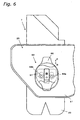
- the cover 25 which is a characteristic feature of the present invention, will be described using Figures 3 , 4 , and 5 .
- the cover 25 is made up of a cover main body 61 and an attachment/detachment mechanism 62.
- the cover main body 61 is shaped such that it covers the entire link mechanism 24.
- An elliptical bulged part 63 is provided in the approximate middle of the cover main body 61 and a long hole 64 is provided in the middle of the bulged part 63.
- the attachment/detachment mechanism 62 includes a slide member 65 arranged such that it can slide freely in the long hole 64, an attachment/detachment operating member 66, an engaging member 67, and a nut 68 that fastens the engaging member 67 to the attachment/detachment operating member 66 with the slide member 65 disposed there-between.
- the slide member 65 is shaped such that its short side is approximately the same size as that of the long hole 64 but its long side is shorter, and the slide member 65 is arranged such that it can move in the directions of arrows O and P within the long hole 64.
- the attachment/detachment operating member 66 is mounted to the outside of the cover main body 61 and has a somewhat larger vertical dimension than the bulged part 63 to facilitate easy operation by hand.
- the engaging part 67 is arranged on the inside of the cover main body 61 and has notches in two locations in a lower portion thereof.
- Nuts 69a, 69b having narrowed bases are screwed onto the support shafts 40a, 40b.
- the notches provided in the engaging part 67 engage with the bases of the nuts 69a, 69b.
- the cover main body 61 can be fixed in a prescribed position by engaging the notches of the engaging part 67 with the nuts 69a, 69b.
- the link mechanism 24 is so arranged as to be concentrated on one side of the box-like body 20, only one cover 25 is needed to cover the link mechanism 24.
- the cover 25 can be freely attached to and detached from the box-like body 20, it is easier to clean the inside of the cover 25 as well as the main unit case 3 and it is also easier to perform maintenance on the link mechanism 24.
- the first and second weighing hoppers 8a, 8b differ from the pool hopper 7 in that they are connected to load cells 12a, 12b and the articles supplied to the first and second weighing hoppers 8a, 8b are weighed by the load cells 12a, 12b.
- the first weighing hopper 8a (which is arranged closer to the main unit case 3) will now be described in detail.
- the first weighing hopper 8a has a rectangular box-like body (pipe-like body) 80 that is open at the top and bottom and first and second gates 81, 82 mounted to a lower portion thereof.
- a plate 83 is attached to one side face of the box-like body 80.
- a link mechanism 84 for driving the first and second gates 81, 82 is arranged on the plate 83.
- Also mounted to the plate 83 is a cover 85 for covering the link mechanism 84. This cover is a characteristic feature of the present invention.
- a drive shaft 91 extends from the open/close drive mechanism 11a of the main unit case 3 to a lower portion of the plate 83 and its tip end engages with a support shaft 94 that is supported in a freely rotatable manner on a support member 93 fixed with nuts 92, 92.
- An input link 95 is supported on the support shaft 94 in such a manner that it can swing freely in the directions of arrows R and S.
- a roller 96 is provided on the other end of the input link 95 in such a manner that it can rotate freely.
- a drive link 97 having a U-shaped tip part is fixed to a support shaft 98 and a driven link 99 is fixed to a support shaft 100.
- the support shafts 98, 100 are provided on opposite sides of the approximate middle of the plate 83 in such a manner that they can turn freely in the directions of arrows T, U and V, W, respectively.
- the roller 96 is arranged in the tip part of the drive link 97 such that it can slide freely there-within.
- the drive link 97 and the driven link 99 are coupled together through an intermediate link 101 by mean of support shafts 101a, 101b.
- the gates 81, 82 are fixed to the support shafts 98, 100 with brackets 81 a, 82a.
- the links 95, 97, 99, 101 of the link mechanism 84 are mounted to their respective support shafts 94, 98, 100, 101a, 101b using bolts and nuts. Also, a bolt is used to fasten the roller 96 to the input link 95.
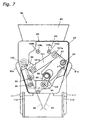
- the link mechanism 84 of the first weighing hopper 8a will now be described.
- the input link 95 supported on the support shaft 94 is swung in the direction of the arrow R by the drive shaft 91 of the open/close drive mechanism 11a.
- the roller 96 provided on the other end of the input link 95 slides generally downward (i.e., downward as shown in Figure 7 ) inside the generally U-shaped part of the drive link 97 and causes the drive link 97 to swing in the direction of the arrow T about the support shaft 98.
- the first gate 81 which is fixed to the support shaft 98 by the bracket 81 a, moves in the same direction and opens the bottom opening of the box-like body 80.
- the intermediate link 101 connected to the drive link 97 causes the driven link 99 to swing in the direction of the arrow V about the support shaft 100.
- the second gate 82 which is fixed to the support shaft 100 by the bracket 82a, moves simultaneously and opens the bottom opening of the box-like body 80.
- the link mechanism 84 can be arranged in such a manner as to be concentrated on one side of the box-like body 80.
- Mounting parts 110 for mounting the first weighing hopper 8a to the main unit case 3 are provided on the plate 83 of the first weighing hopper 8a and configured to extend toward the main unit case 3.
- Outwardly-protruding engaging rods 111, 111 are provided on comparatively upper portions of the mounting parts 110, 110 and notches are provided on comparatively lower parts.
- a pair of hopper support parts 112 configured to extend toward the first weighing hopper 8a is connected to the load cell 12a inside the main unit case 3.
- An engaging rod 113 is provided such that it spans between comparatively lower portions of the tip edges of the hopper support parts 112 and notches that can engage with the engaging rods 111, 111 are provided in comparatively upper portions of the same.
- the distance between the tip edges of these hopper support members 112 is slightly larger than the distance between the mounting parts 110, 110 of the first weighing hopper 8a.
- the engaging rods 111, 111 of the mounting parts 110, 110 of the first weighing hopper 8a engage with the notches in the hopper support members 112 of the main unit case 3 and the engaging rod 113, 113 of the hopper support members 112 of the main unit case 3 engages with the notches of the first weighing hopper 8a.
- the first weighing hopper 8a is supported on the main unit case 3.
- the first weighing hopper 8a can be easily attached to and detached from the main unit case 3.
- explanation of the second weighing hopper 8b has been omitted, the second weighing hopper 8b is mounted to the sub case 4 using the same method as the similarly constructed first weighing hopper 8a.
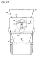
- the cover 85 which is a characteristic feature of the present invention, will be described using Figures 7 , 8 , and 9 .
- the cover 85 is made up of a cover main body 121 and an attachment/detachment mechanism 122.
- the cover main body 121 is shaped such that it covers the entire link mechanism 84 and is provided with a slight step between the upper part and lower part thereof.
- the cover main body 121 is provided with a long hole 123 in the vicinity of the center of the upper part thereof.
- the support shaft 94 protrudes from a hole provided in the lower part of the cover main body 121.
- the attachment/detachment mechanism 122 includes a slide member 124 arranged such that it can slide in the long hole 123, an attachment/detachment operating member 125, an engaging member 126, and a nut 127 that fastens the engaging member 126 to the attachment/detachment operating member 125 with the slide member 124 disposed there-between.
- the slide member 124 is shaped such that its short side is approximately the same size as that of the long hole 123 but its long side is shorter, and the slide member 124 is arranged such that it can move in the directions of arrows X and Y within the long hole 123.
- the attachment/detachment operating member 125 is mounted to the outside of an upper portion of the cover main body 121.
- the engaging part 126 is arranged on the inside of the cover main body 121 and has notches in two locations in a lower portion thereof.
- Nuts 129a, 129b having narrowed bases are screwed onto bolts 128a, 128b mounted above the intermediate link 101.
- the cover main body 121 can be fixed in a prescribed position by engaging the notches of the engaging part 126 with the nuts 129a, 129b.
- the link mechanism 84 is so arranged as to be concentrated on one side of the box-like body 80, only one cover 85 is needed to cover the link mechanism 84.
- the cover 85 can be freely attached to and detached from the box-like body 80, it is easier to clean the inside of the cover 85 as well as the main unit case 3 (or the sub case 4 in the case of the second weighing hopper 8b) and it is also easier to perform maintenance on the link mechanism 84.
- explanation of the second weighing hopper 8b is omitted because the construction is the same, the same operational effects are obtained with the second weighing hopper 8b.
- a combination weighing apparatus 1 in accordance with the embodiment presented heretofore is configured such that pool hoppers 7...7 and weighing hoppers 8a...8a, 8b...8b are arranged in rows
- the present invention can also be applied to a combination weighing apparatus in which the troughs, pool hoppers, and weighing hoppers are arranged in a circular fashion.
- the present invention features the idea of attaching covers configured to cover the link mechanisms of the hoppers in a combination weighing apparatus, the present invention can solve the problem of fragments of resin parts and other component parts that have been damaged by the vibrations resulting from opening and closing the gates, as well as bolts, nuts, and other parts of the link mechanism that have become loose due to vibrations, falling and becoming mixed into the articles. Also, since the link mechanism is so arranged as to be concentrated on one side of the box-like bodies, only one cover is needed to cover each link mechanism. Moreover, cleaning and maintenance can be accomplished more easily because the covers are constructed in such a manner that they can be attached and detached easily.
Claims (7)
- Behälter (7), umfassend:einen röhrenförmigen Körper (20) mit oberen und unteren Öffnungen;einen Verschluss (21, 22) der gestaltet ist, um frei zu schwingen in Bezug auf den röhrenförmigen Körper (20) und, um die untere Öffnung des röhrenförmigen Körpers (20) zu öffnen und zu schließen;einen Verbindungsmechanismus (24), der gestaltet ist zur Übertragung einer Antriebskraft von einer externen Antriebsquelle auf solch eine Art,dass der Verschluss schwingt,
dadurch gekennzeichnet, dass eine Abdeckung (25) den gesamten Verbindungsmechanismus (24) bedeckt, um Bruchstücke am Herausfallen aus der Abdeckung (25) zu hindern,die Abdeckung (25) ein Eingriffsbauteil (67) aufweist, unddie Abdeckung (25) an dem röhrenförmigen Körper (20) befestigt ist durch abwärts Eingreifen einer Kerbe des Eingriffsbauteils (67) in eine Mutter (69a) des röhrenförmigen Körpers (20). - Behälter nach Anspruch 1, wobei der Verbindungsmechanismus (24) auf einer Seite des röhrenförmigen Körpers (25) angeordnet ist.
- Behälter nach Anspruch 1, wobeidie Abdeckung (25) einen Hauptkörper (61) mit einer Bohrung (64) aufweist,ein Gleitbauteil (65) gleitbar mit der Bohrung (64) verbunden ist, unddas Eingriffsbauteil (67) mit dem Gleitbauteil (65) verbunden ist und eine Kerbe aufweist, unddie Abdeckung (25) an dem röhrenförmigen Körper (20) befestigt ist durch Eingreifen der Kerbe des Eingriffsbauteils (67) in die Mutter (69a) des röhrenförmigen Körpers (20).
- Wiegevorrichtung (1) zum Wiegen von Gegenständen, umfassend:ein Hauptgehäuse (3) mit einer ersten Antriebsquelle (10) und einer Messdose (12a), die darin installiert ist;eine Rinne (6), die sich über dem Hauptgehäuse (3) befindet, um Gegenstände zu transportieren; undeinen ersten Behälter (7), der sich auf dem Hauptgehäuse (3) unterhalb der Rinne (6) abstützt und einschließt:einen ersten röhrenförmigen Körper mit oberen und unteren Öffnungen;einen ersten Verschluss, der gestaltet ist, um frei zu schwingen in Bezug auf den ersten röhrenförmigen Körper, und um die untere Öffnung des ersten röhrenförmigen Körpers zu öffnen und zu schließen;einen ersten Verbindungsmechanismus, der gestaltet ist zum Übertragen einer Antriebsleistung von der ersten Antriebsquelle in solch einer Art, dass der Verschluss schwingt,dadurch gekennzeichnet,dass eine erste Abdeckung den gesamten ersten Verbindungsmechanismus bedeckt um Bruchstücke am Herausfallen aus der Abdeckung (25) zu hindern,die erste Abdeckung ein Eingriffsbauteil (67) aufweist, unddie erste Abdeckung an dem ersten röhrenförmigen Körper befestigt ist durch abwärts Eingreifen einer Kerbe des Eingriffsbauteils (67) in eine Mutter (69a) des ersten röhrenförmigen Körpers.
- Wiegevorrichtung nach Anspruch 4, wobei der erste Verbindungsmechanismus auf einer Seite des ersten röhrenförmigen Körpers angeordnet ist.
- Wiegevorrichtung nach Anspruch 4, wobeieine erste Abdeckung einen Hauptkörper mit einer Bohrung aufweist,ein Gleitbauteil verschiebbar mit der Bohrung verbunden ist, und das Eingriffsbauteil mit dem Gleitbauteil verbunden ist und eine Kerbe aufweist, unddie erste Abdeckung an dem ersten röhrenförmigen Körper befestigt ist durch Eingreifen der Kerbe des Eingriffsbauteils in die Mutter (69a) des ersten röhrenförmigen Körpers.
- Wiegevorrichtung nach Anspruch 4, weiterhin umfassend:eine zweite Antriebsquelle (11a), die in dem Hauptgehäuse (3) installiert ist; undeinen zweiten Behälter (8a), der sich auf dem Hauptgehäuse (3) unterhalb des ersten Behälters (7) abstützt und einschließt:einen zweiten röhrenförmigen Körper mit oberen und unteren Öffnungen;einen zweiten Verschluss, der gestaltet ist um frei zu schwingen in Bezug auf den zweiten röhrenförmigen Körper, und um die untere Öffnung des zweiten röhrenförmigen Körpers zu öffnen und zu schließen;einen zweiten Verbindungsmechanismus, der gestaltet ist zur Übertragung der Antriebsleistung von der zweiten Antriebsquelle auf solch eine Art, um den zweiten Verschluss zu schwingen; undeine zweite Abdeckung, die den gesamten zweiten Verbindungsmechanismus abdeckt, unddie Messdose, welche die Gegenstände in dem zweiten Behälter wiegt.
Applications Claiming Priority (3)
| Application Number | Priority Date | Filing Date | Title |
|---|---|---|---|
| JP2002185881 | 2002-06-26 | ||
| JP2002185881A JP3819330B2 (ja) | 2002-06-26 | 2002-06-26 | ホッパ及びそれを備えた計量装置 |
| PCT/JP2003/007947 WO2004003491A1 (ja) | 2002-06-26 | 2003-06-23 | ホッパ及びそれを備えた計量装置 |
Publications (3)
| Publication Number | Publication Date |
|---|---|
| EP1445593A1 EP1445593A1 (de) | 2004-08-11 |
| EP1445593A4 EP1445593A4 (de) | 2005-10-12 |
| EP1445593B1 true EP1445593B1 (de) | 2009-03-25 |
Family
ID=29996751
Family Applications (1)
| Application Number | Title | Priority Date | Filing Date |
|---|---|---|---|
| EP03733556A Expired - Fee Related EP1445593B1 (de) | 2002-06-26 | 2003-06-23 | Behälter und dosiervorrichtung dafür |
Country Status (6)
| Country | Link |
|---|---|
| US (1) | US7053317B2 (de) |
| EP (1) | EP1445593B1 (de) |
| JP (1) | JP3819330B2 (de) |
| AU (1) | AU2003243956A1 (de) |
| DE (1) | DE60326813D1 (de) |
| WO (1) | WO2004003491A1 (de) |
Families Citing this family (7)
| Publication number | Priority date | Publication date | Assignee | Title |
|---|---|---|---|---|
| FR2874211B1 (fr) * | 2004-08-10 | 2006-10-20 | Movidis Sa | Dispositif de transfert et de dosage de matiere pulverulente ou granuleuse contenue dans une tremie |
| US9228883B2 (en) * | 2010-09-06 | 2016-01-05 | Yamato Scale Co., Ltd. | Weighing unit and combination weigher using the same |
| AU2015381840B2 (en) * | 2015-02-04 | 2021-06-24 | Ishida Co., Ltd. | Combination weighing device |
| JP6465356B2 (ja) * | 2015-07-02 | 2019-02-06 | 大和製衡株式会社 | ホッパ及びこれを備えた組合せ秤 |
| JP6707759B2 (ja) * | 2016-09-20 | 2020-06-10 | 株式会社イシダ | ホッパ及び組合せ計量装置 |
| JP6993680B2 (ja) * | 2017-11-29 | 2022-01-13 | 株式会社イシダ | ホッパ及びそれを備えた組合せ計量装置 |
| JP7474473B2 (ja) | 2020-03-18 | 2024-04-25 | 株式会社イシダ | 計量機構 |
Family Cites Families (7)
| Publication number | Priority date | Publication date | Assignee | Title |
|---|---|---|---|---|
| US5379923A (en) * | 1992-06-17 | 1995-01-10 | Eagle Packaging Corp. | Hopper for a weighing machine |
| US6188029B1 (en) * | 1996-07-03 | 2001-02-13 | Ishida Co., Ltd. | Weighing apparatus having improved hopper detachability |
| JP4149114B2 (ja) | 2000-03-17 | 2008-09-10 | アンリツ産機システム株式会社 | 組合せ計量装置 |
| US6674021B2 (en) * | 2000-03-17 | 2004-01-06 | Anritsu Corporation | Combination weighing equipment with sealed happer door driving mechanisms to facilitate cleaning |
| JP4652529B2 (ja) | 2000-06-13 | 2011-03-16 | アンリツ産機システム株式会社 | 組合せ計量装置 |
| JP2001349768A (ja) | 2000-06-07 | 2001-12-21 | Anritsu Corp | 組合せ計量装置 |
| JP4566340B2 (ja) | 2000-06-08 | 2010-10-20 | アンリツ産機システム株式会社 | 計量装置 |
-
2002
- 2002-06-26 JP JP2002185881A patent/JP3819330B2/ja not_active Expired - Fee Related
-
2003
- 2003-06-23 EP EP03733556A patent/EP1445593B1/de not_active Expired - Fee Related
- 2003-06-23 AU AU2003243956A patent/AU2003243956A1/en not_active Abandoned
- 2003-06-23 WO PCT/JP2003/007947 patent/WO2004003491A1/ja active Application Filing
- 2003-06-23 US US10/496,396 patent/US7053317B2/en not_active Expired - Fee Related
- 2003-06-23 DE DE60326813T patent/DE60326813D1/de not_active Expired - Lifetime
Also Published As
| Publication number | Publication date |
|---|---|
| US7053317B2 (en) | 2006-05-30 |
| JP2004028805A (ja) | 2004-01-29 |
| EP1445593A4 (de) | 2005-10-12 |
| DE60326813D1 (de) | 2009-05-07 |
| US20050087372A1 (en) | 2005-04-28 |
| EP1445593A1 (de) | 2004-08-11 |
| AU2003243956A1 (en) | 2004-01-19 |
| JP3819330B2 (ja) | 2006-09-06 |
| WO2004003491A1 (ja) | 2004-01-08 |
Similar Documents
| Publication | Publication Date | Title |
|---|---|---|
| EP1445593B1 (de) | Behälter und dosiervorrichtung dafür | |
| DE69724088T2 (de) | Messvorrichtung zur vereinfachung des montierens und auswechselns eines behälters | |
| EA005328B1 (ru) | Цепной транспортёр в виде весов | |
| CN104272068A (zh) | 计量装置 | |
| US6607098B2 (en) | Allocating mechanism for a weighing apparatus | |
| BR112013010327B1 (pt) | tampa protetora que cobre a extremidade de descarga de uma correia transportadora transportando material solto | |
| US6709578B2 (en) | Tilt-out frame for a filter screen | |
| EP1062485B1 (de) | Wägeeinrichtung | |
| EP3879245A1 (de) | Kombinationswägevorrichtung | |
| US4089407A (en) | Constant belt tensioner | |
| GB2086593A (en) | Weighing device | |
| US3324960A (en) | Weighing mechanism for conveyor | |
| DE10249031A1 (de) | Bandförderer und Reinigungsvorrichtung | |
| CN1035569C (zh) | 软化固体称重装置 | |
| CN109178871B (zh) | 一种易拆装型烟用滤棒卸料挡条装置 | |
| EP2382451B1 (de) | Förderbandwaage | |
| CN218600663U (zh) | 一种四托辊电子皮带秤 | |
| CN219155330U (zh) | 一种可拆卸的料斗 | |
| CN2669150Y (zh) | 双向给料电子皮带秤 | |
| CN220657847U (zh) | 一种选煤加工用破碎筛分装置 | |
| WO2022044155A1 (ja) | 物品搬送用フィーダ及びそれを備えた組合せ秤 | |
| US2957578A (en) | Plansifters | |
| CN215171942U (zh) | 一种具有张紧功能的提升机链轮结构 | |
| CN217458044U (zh) | 一种供料系统及智能化煤炭分析设备 | |
| CN214166241U (zh) | 一种轻质物料皮带输送机 |
Legal Events
| Date | Code | Title | Description |
|---|---|---|---|
| PUAI | Public reference made under article 153(3) epc to a published international application that has entered the european phase |
Free format text: ORIGINAL CODE: 0009012 |
|
| 17P | Request for examination filed |
Effective date: 20040526 |
|
| AK | Designated contracting states |
Kind code of ref document: A1 Designated state(s): AT BE BG CH CY CZ DE DK EE ES FI FR GB GR HU IE IT LI LU MC NL PT RO SE SI SK TR |
|
| AX | Request for extension of the european patent |
Extension state: AL LT LV MK |
|
| A4 | Supplementary search report drawn up and despatched |
Effective date: 20050826 |
|
| RIC1 | Information provided on ipc code assigned before grant |
Ipc: 7G 01G 19/387 A Ipc: 7B 65G 65/40 B Ipc: 7G 01G 13/16 B |
|
| DAX | Request for extension of the european patent (deleted) | ||
| RBV | Designated contracting states (corrected) |
Designated state(s): DE FR GB IT |
|
| 17Q | First examination report despatched |
Effective date: 20051123 |
|
| 17Q | First examination report despatched |
Effective date: 20051123 |
|
| GRAP | Despatch of communication of intention to grant a patent |
Free format text: ORIGINAL CODE: EPIDOSNIGR1 |
|
| GRAS | Grant fee paid |
Free format text: ORIGINAL CODE: EPIDOSNIGR3 |
|
| GRAA | (expected) grant |
Free format text: ORIGINAL CODE: 0009210 |
|
| AK | Designated contracting states |
Kind code of ref document: B1 Designated state(s): DE FR GB IT |
|
| REG | Reference to a national code |
Ref country code: GB Ref legal event code: FG4D |
|
| REF | Corresponds to: |
Ref document number: 60326813 Country of ref document: DE Date of ref document: 20090507 Kind code of ref document: P |
|
| PLBE | No opposition filed within time limit |
Free format text: ORIGINAL CODE: 0009261 |
|
| STAA | Information on the status of an ep patent application or granted ep patent |
Free format text: STATUS: NO OPPOSITION FILED WITHIN TIME LIMIT |
|
| 26N | No opposition filed |
Effective date: 20091229 |
|
| PGFP | Annual fee paid to national office [announced via postgrant information from national office to epo] |
Ref country code: DE Payment date: 20120622 Year of fee payment: 10 |
|
| PGFP | Annual fee paid to national office [announced via postgrant information from national office to epo] |
Ref country code: FR Payment date: 20120705 Year of fee payment: 10 Ref country code: GB Payment date: 20120622 Year of fee payment: 10 |
|
| PGFP | Annual fee paid to national office [announced via postgrant information from national office to epo] |
Ref country code: IT Payment date: 20120627 Year of fee payment: 10 |
|
| GBPC | Gb: european patent ceased through non-payment of renewal fee |
Effective date: 20130623 |
|
| REG | Reference to a national code |
Ref country code: DE Ref legal event code: R119 Ref document number: 60326813 Country of ref document: DE Effective date: 20140101 |
|
| REG | Reference to a national code |
Ref country code: FR Ref legal event code: ST Effective date: 20140228 |
|
| PG25 | Lapsed in a contracting state [announced via postgrant information from national office to epo] |
Ref country code: DE Free format text: LAPSE BECAUSE OF NON-PAYMENT OF DUE FEES Effective date: 20140101 Ref country code: GB Free format text: LAPSE BECAUSE OF NON-PAYMENT OF DUE FEES Effective date: 20130623 |
|
| PG25 | Lapsed in a contracting state [announced via postgrant information from national office to epo] |
Ref country code: IT Free format text: LAPSE BECAUSE OF NON-PAYMENT OF DUE FEES Effective date: 20130623 Ref country code: FR Free format text: LAPSE BECAUSE OF NON-PAYMENT OF DUE FEES Effective date: 20130701 |