EP1445494A2 - Stellelement mit Lageerkennung - Google Patents
Stellelement mit Lageerkennung Download PDFInfo
- Publication number
- EP1445494A2 EP1445494A2 EP04100364A EP04100364A EP1445494A2 EP 1445494 A2 EP1445494 A2 EP 1445494A2 EP 04100364 A EP04100364 A EP 04100364A EP 04100364 A EP04100364 A EP 04100364A EP 1445494 A2 EP1445494 A2 EP 1445494A2
- Authority
- EP
- European Patent Office
- Prior art keywords
- hall sensor
- magnet
- piston rod
- housing
- turntable
- Prior art date
- Legal status (The legal status is an assumption and is not a legal conclusion. Google has not performed a legal analysis and makes no representation as to the accuracy of the status listed.)
- Granted
Links
- 238000001514 detection method Methods 0.000 claims abstract description 33
- 230000004907 flux Effects 0.000 claims abstract description 24
- 230000000694 effects Effects 0.000 claims abstract description 5
- 230000033001 locomotion Effects 0.000 claims description 31
- 230000008859 change Effects 0.000 claims description 15
- 230000008901 benefit Effects 0.000 description 4
- 238000013461 design Methods 0.000 description 4
- 239000012528 membrane Substances 0.000 description 3
- 238000006243 chemical reaction Methods 0.000 description 2
- 238000011109 contamination Methods 0.000 description 2
- 238000005260 corrosion Methods 0.000 description 2
- 230000007797 corrosion Effects 0.000 description 2
- 238000011156 evaluation Methods 0.000 description 2
- 230000006698 induction Effects 0.000 description 2
- 239000002184 metal Substances 0.000 description 2
- 238000000034 method Methods 0.000 description 2
- 230000008569 process Effects 0.000 description 2
- 239000000853 adhesive Substances 0.000 description 1
- 230000001070 adhesive effect Effects 0.000 description 1
- 230000033228 biological regulation Effects 0.000 description 1
- 230000005540 biological transmission Effects 0.000 description 1
- 230000003247 decreasing effect Effects 0.000 description 1
- 238000011161 development Methods 0.000 description 1
- 230000018109 developmental process Effects 0.000 description 1
- 238000011990 functional testing Methods 0.000 description 1
- 230000036039 immunity Effects 0.000 description 1
- 238000004519 manufacturing process Methods 0.000 description 1
- 239000000463 material Substances 0.000 description 1
- 230000007246 mechanism Effects 0.000 description 1
- 230000035945 sensitivity Effects 0.000 description 1
- 239000000126 substance Substances 0.000 description 1
- 230000001960 triggered effect Effects 0.000 description 1
- 238000003466 welding Methods 0.000 description 1
Images
Classifications
-
- F—MECHANICAL ENGINEERING; LIGHTING; HEATING; WEAPONS; BLASTING
- F15—FLUID-PRESSURE ACTUATORS; HYDRAULICS OR PNEUMATICS IN GENERAL
- F15B—SYSTEMS ACTING BY MEANS OF FLUIDS IN GENERAL; FLUID-PRESSURE ACTUATORS, e.g. SERVOMOTORS; DETAILS OF FLUID-PRESSURE SYSTEMS, NOT OTHERWISE PROVIDED FOR
- F15B15/00—Fluid-actuated devices for displacing a member from one position to another; Gearing associated therewith
- F15B15/20—Other details, e.g. assembly with regulating devices
- F15B15/28—Means for indicating the position, e.g. end of stroke
- F15B15/2807—Position switches, i.e. means for sensing of discrete positions only, e.g. limit switches
-
- F—MECHANICAL ENGINEERING; LIGHTING; HEATING; WEAPONS; BLASTING
- F15—FLUID-PRESSURE ACTUATORS; HYDRAULICS OR PNEUMATICS IN GENERAL
- F15B—SYSTEMS ACTING BY MEANS OF FLUIDS IN GENERAL; FLUID-PRESSURE ACTUATORS, e.g. SERVOMOTORS; DETAILS OF FLUID-PRESSURE SYSTEMS, NOT OTHERWISE PROVIDED FOR
- F15B15/00—Fluid-actuated devices for displacing a member from one position to another; Gearing associated therewith
- F15B15/08—Characterised by the construction of the motor unit
- F15B15/10—Characterised by the construction of the motor unit the motor being of diaphragm type
-
- Y—GENERAL TAGGING OF NEW TECHNOLOGICAL DEVELOPMENTS; GENERAL TAGGING OF CROSS-SECTIONAL TECHNOLOGIES SPANNING OVER SEVERAL SECTIONS OF THE IPC; TECHNICAL SUBJECTS COVERED BY FORMER USPC CROSS-REFERENCE ART COLLECTIONS [XRACs] AND DIGESTS
- Y10—TECHNICAL SUBJECTS COVERED BY FORMER USPC
- Y10T—TECHNICAL SUBJECTS COVERED BY FORMER US CLASSIFICATION
- Y10T137/00—Fluid handling
- Y10T137/8158—With indicator, register, recorder, alarm or inspection means
- Y10T137/8225—Position or extent of motion indicator
- Y10T137/8242—Electrical
Definitions
- the invention relates to an actuator according to the preamble of claim 1. Furthermore The invention relates to a modular system for creating the control element according to the genus of the independent claim 10.
- Actuators for actuating actuators such. B. flaps, rotary valves or valves are widely known in the art. For many applications it is necessary to at least the end positions one with the drive of the Actuating element correspondingly connected to detect and close monitor. It is known from EP 0 345 459 B1, within a pressure chamber pneumatic actuator to arrange an electrical switch, which depends can be actuated relative to the housing by the position of the piston rod. When reaching the switch is triggered at a predetermined position by the piston rod and outputs an electrical signal. The switch is deliberately in the pressure room of the pneumatic actuator arranged so as to prevent contamination and corrosion to be protected by aggressive media. Control elements are likewise known to the person skilled in the art is known in which the position detection via the acceptance of a signal from a grinding potentiometer he follows.
- a disadvantage of these solutions is, on the one hand, the susceptibility to wear of these contact-controlled ones End position detection and the resulting vulnerability with regard to a reliable signal output. There is also a risk of corrosion of the contacts or the sliding contacts of the potentiometer, especially when in contact with chemicals or aggressive media. Another disadvantage of the grinding potentiometer is that occurring temperature drift with strongly changing temperatures and thereby the Unreliability of the output signal.
- the object of the invention is therefore to provide an actuator with an integrated To create position detection, which is simple, with a wear-free Position detection works and by simply replacing fewer parts within one wide range of applications is applicable.
- Another object of the invention is not only to offer an end position detection of the control element, but also also the possibility to record the path between the end positions. This task will solved by the features of claims 1 and 10.
- the actuating element has a housing with one arranged therein Drive and at least one means for position detection, one in the housing movably mounted piston rod corresponding to the drive to exert a force effect connected is.
- the means for position detection consists of at least a stationary Hall sensor and at least one to the Hall sensor corresponding, movably arranged magnets. That emanating from the magnet magnetic field generated depending on the position of the magnet relative to the Hall sensor a magnetic flux through the Hall sensor.
- the drive is preferably via a vacuum housing with membrane, i.e. pneumatically implemented, but can also be electrical, be carried out mechanically or hydraulically.
- the execution of the control element Made entirely of plastic, a mix of materials between plastic and metal or consist entirely of metal.
- the piston rod movably mounted in the housing has preferably a square cross section, but can also be used without restriction have a circular (oval) or polygonal cross-section. Likewise can they can be straight or curved. It corresponds to the drive connected, the connection being detachable or non-detachable in nature and it this connection is also possible via an intermediate gear or change-over gear or carry out a different kind of redirection.
- the position detection is in the control element according to the invention contactlessly via a stationary in or Hall sensor arranged on the housing with at least one corresponding thereto movable magnet realized. The magnetic generated by the magnet Depending on the position of the magnet relative to the Hall sensor, the field generates a magnetic flux through the Hall sensor and thereby a changed signal at its output.
- the piston rod is at least a turntable correspondingly connected to a shaft and thus converts one translatory movement of the piston rod into a rotary movement of the shaft around.
- This is comparable e.g. B. with the crank mechanism of a bicycle, in which an approximate translational movement of the leg with respect to the pedals in a rotary Movement on the chain drive is converted.
- the piston rod movable in the housing and corresponding to the drive of the control element connected, it is possible for them to allow a certain angular offset, and so on an approximate circular path of the connection point between the piston rod and Turntable to follow in the outer area of the turntable.
- the so driven shaft can e.g. B. a switching flap, a switching flap assembly or a Turn the rotary valve within a certain angular range.
- the turntable can take the form of an essentially circular disk with volume, but here are the design options almost no limits. So the turntable can also be square or be oval in shape and in extreme cases even consist of only one deflecting rod. The kinematic conversions necessary for this should be well known to the skilled person and need no further examples.
- the Hall sensor is the position detection releasably arranged in the housing of the actuating element.
- a detachable connection such as. B. a screw connection, a clip connection or a pure plug connection as well as other in the state of Technically known types of connection is releasably connected to the housing.
- the Hall sensor is non-detachable in the housing arranged the actuator.
- the Hall sensor is attached to the intended one Pick-up point in the housing via an adhesive process or a welding process or other means known in the art for the permanent connection of two elements connected to the housing. Due to the inseparable connection possible Error caused by a change in the position of the Hall sensor, e.g. B. by vibrations and the associated falsified signal output can be minimized.
- a special embodiment The invention provides that to increase the magnetic flux of the movable arranged magnet arranged at least one flux guide plate on the Hall sensor is and this flux guide plate in predetermined positions, the poles of the magnet in the essentially covered.
- This flow baffle is for one corresponding to the Hall sensor and covered at least in one Partial area the path of the magnet guided in the housing when the position changes through the piston rod.
- the shape of the flow guide plate is preferably the same a U-shape, the two legs of the U respectively the north and the south pole of the Cover the magnet at at least one point of the magnet on its path of motion.
- the Hall sensor detects the translational change in position of the piston rod.
- the at least one magnet is preferably integrated into the piston rod, so that the magnetic flux is as unimpeded as possible.
- the magnet can be in Recesses are integrated in the piston rod and with it via detachable or non-detachable Connection types are connected.
- the magnet preferably has a cylindrical or pen shape, but other shapes are also conceivable and technically feasible.
- Movement of the piston rod is a relative movement to the stationary Hall sensor is carried out in the Hall sensor as a function of the change in the magnetic flux a different signal for identification from the position of the magnet the change in position or also to identify the end positions.
- At least one magnet is on the Turntable arranged and the Hall sensor thus detects the rotational change in position the wave.
- the Hall sensor is arranged stationary in the housing so that it corresponds with a change of position of the magnet by turning the turntable a change in position of the turntable and the correspondingly associated shaft can accommodate. So in a simple way and manner of the angle of rotation starting from a zero position of the driven shaft be recorded.
- the preferred application here are rotary valves which are connected to the Shaft are connected, or also flaps or flap walls, there are however, other applications are conceivable and possible in which the position of the Shaft and the angle of rotation of the shaft are relevant for an evaluation.
- a programmable Hall sensor In which The use of a programmable Hall sensor is still possible Two-point comparison with the functional test including the component to be switched. This is e.g. B. possible during production directly at the end of the belt and thus increases in very high time and cost efficiency.
- the control element can also be included calibrate the component to be switched so easily and cheaply, which results in a very leads to high accuracy.
- the data output by the Hall sensor can thus z. B. passed on to the engine control unit in the vehicle and thus meet the requirements to the On Board Diagnostics (OBD), which are used in modern motor vehicles the exhaust gas regulations and to achieve redundancies.
- OBD On Board Diagnostics
- At least a magnet arranged on the turntable can be released with the turntable or be permanently connected and changed by the rotary movement of the turntable its magnetic flux relative to the fixed Hall sensor. The shape of the magnet has no influence on the function of the position detection.
- the Hall sensor has for detection an output for a digital signal from predetermined positions. This is it possible, simply z. B. to detect and output the end positions of the movement.
- the Hall sensor functions as a simple end position detection and thus replaces that from the State-of-the-art make contact. Depending on the signal strength and Any programming of the Hall sensor can be done almost arbitrarily realize exact end position and position detection.
- the Hall sensor has an output for an analog signal to detect a position profile.
- the output signal changes depending on the change in the Magnetic flux. This change occurs as soon as the movable at least one magnet executes a relative movement to the stationary Hall sensor.
- a evaluation logic implemented either in the Hall sensor or externally available each movement point of the piston rod or the rotary valve can be recognized and output. This option therefore also allows conclusions to be drawn about the current one Position between the two end positions.
- actuating element is in realizing the individual variants in a modular system.
- this Modular system it is possible to use actuators to drive actuators produce, the individual parts of the modular system can be freely combined with each other are and with the different combination of control elements with or without Position detection and with or without force redirection from translational to rotary Result in force.
- the design options vary from a simple one Control element with piston rod and translatory force effect up to one control element with piston rod, corresponding here with connected turntable Redirection of the force effect from a translatory movement to a rotary movement Movement with a position detection, the position detection the entire movement detected.
- the modular system includes a housing with a drive, at least two movable piston rods that can be guided in the housing and can be used optionally, at least two rotary valves for the corresponding optional connection with one of the piston rods and at least one Hall sensor.
- the at least two Piston rods include at least one piston rod that has no magnet and at least one piston rod equipped with at least one magnet is.
- the actual design of the piston rod can be identical and differ only in the subsequent introduction of the at least one magnet. It is therefore also possible for the modular system to have at least two identical ones Has piston rods and additionally at least one magnet for subsequent Attachment to the piston rod is added to the modular system.
- At least two turntables differ from each other just as with the piston rods by arranging at least one magnet on one of the turntables.
- both turntables can be constructed identically and the at least one Magnet can be retrofitted to one of the two turntables.
- the turntables with or without a magnet to connect it optionally with the piston rod in order to redirect the force to realize.
- the turntables also have the option of a connection a wave for z. B. on a rotary valve or a flap assembly.
- a Hall sensor fixed either in the area of the movement Piston rod or alternatively stationary in the area of the movement of the turntable to arrange.
- the use of the Hall sensor is optional and is done here of course, preferably in combination with either that with at least one magnet equipped piston rod or that equipped with at least one magnet Turntable.
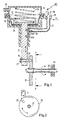
- FIG. 1 shows a schematic view of an actuator 10, here as a vacuum actuator executed, with a vacuum connection 11, which to a vacuum chamber 12 is connected with a spring 13 embedded therein.
- the vacuum room is formed from an upper housing part 14, which seals with a lower housing part 15 is connected.
- the spring 13 is supported on the one hand in the upper housing part 14 and on the other hand on a spring support 16 which is connected to a piston rod 17 is, from.
- the piston rod 17 is movable in the lower region of the lower housing part 15 led out of this, and through a membrane 18, the vacuum chamber 12th sealingly separated from the environment.
- the membrane 18 and the spring support 16 are connected to each other, whereby the piston rod 17th is tightened against the spring force of the spring 13 in the direction of the upper housing part 14.
- the piston rod 17 has a through bore 19, through which a pin 20 which is rotatably mounted eccentrically in a turntable 22 is reaching out.
- a locking ring 21 is embedded.
- the turntable 22 is concentric firmly connected to a shaft 23, the shaft being supported by a ball bearing 24. Due to the fixed connection between the turntable 22 and shaft 23, a rotational force can are transferred from the turntable to the shaft, whereby in the further course the shaft 23 z.
- a rotary valve or a switching flap assembly which is rotatable is operated, can be connected.
- the piston rod 17 Since the piston rod 17 is movable in the lower part of the housing 15 is stored, it can in the lower region of the circular path at the Turntable 22 follow fixed pin 20 and so translationally upwards Directed movement of the turntable 22 and the shaft 23 connected thereto to a convince rotary motion.
- Two magnets 25a and 25b are arranged in the upper region of the piston rod 17. These are embedded in the piston rod 17 and firmly connected to it. In the lower one The position of the piston rod 17 at the level of the magnet 25a is fixed in the housing Hall sensor 26 arranged. This is via a closed cable guide 27 with a Plug output 28 connected. The system of Hall sensor 26, closed Cable guide 27 and connector outlet 28 is in the upper area of the lower part of the housing 15 clipped into a clipping opening 29 arranged there in the direction X. With this structure of the control element 10, it is possible, either via a Hall sensor 26 with digital Output to detect the two end positions of the piston rod 17, or the entire Path of the piston rod 17 via a Hall sensor 26 with an analog output signal take.
- the lower end position of the piston rod 17 is characterized in that that here the magnet 25a is at the level of the stationary Hall sensor 26.
- the The upper end position of the piston rod 17 is then reached as soon as the magnet 25b opens Height of the Hall sensor 26 is located. Because the Hall sensor 26 changes in the magnetic field strength resp. the magnetic flux responds, it gives an end position signal when reached the highest magnetic field strength. The highest magnetic field strength is then reached as soon as the magnet is exactly at the level of the Hall sensor.
- FIG. 2 shows the section A - A as a side plan view of the turntable 22 1 corresponding components are provided with the same reference numerals.
- the turntable 22 is concentric on the shaft 23 and is connected to it in a rotationally fixed manner.
- the connecting pin 20 between the piston rod 17 and turntable 22 is arranged eccentrically and thus causes translational Movement of the piston rod 17 a rotation of the turntable 22 and thus also the associated shaft 23.
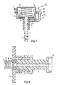
- FIG. 3 shows a schematic view of a variant of the invention Control element 10.
- This pneumatic control element 10 differs from the control element 10 of Figure 1 in that there is no conversion of the translational movement the piston rod 17 in a rotational movement of a shaft 23 becomes. Another important difference is that here on the piston rod 17 only one Magnet 25 is arranged. With a digital design of the Hall sensor, the Hall sensor only the end position of the piston rod 17 when the vacuum is applied Control element 10 are detected. Once the magnet 25 by moving the piston rod 17 in the direction of the upper housing part 14 is in register with the Hall sensor 26 the signal for reaching the end stop is output by the Hall sensor.
- the actuating element 10 shown is in the second end position of the piston rod 17, this being mechanically limited by the walls of the lower housing part 15 becomes.
- This is a simple variant of the control element according to the invention.
- a Hall sensor 26 which has an analog output, can also be used in this Arrangement detect the entire change in position of the piston rod 17. In this case the strength of the magnetic field increases continuously up to the end stop in the vacuum charged form. Through suitable programming and calibration The Hall sensor 26 can also be controlled in this simple form achieve. Should be due to the available space attached to the housing closed cable routing 27 may not be possible, it is also possible with all variants, to work with an open cable guide and the connector output 28 at one to arrange another component in the vicinity of the control element.
- FIG. 4 shows the schematic view of an enlargement of the Hall sensor with it attached flow baffles. Components corresponding to FIG. 1 are the same Provide reference numerals.
- the piston rod 17 goes into the plane of the sheet, the system for position detection is shown in section at the level of the Hall sensor 26. It can be seen that a sensor housing 31 with a plug output 28 into a corresponding receptacle of the lower housing part 15 is clipped. In the sensor housing 31, the Hall sensor 26 and two flux guide plates 30 are embedded. It's closed recognize that the flux guide plates 30 are the magnets embedded in the piston rod 17 25 completely cover in this position.
- the outgoing from the magnet 25 magnetic flux is through the flux guide plates 30 to a three-digit
- the factor increases and increases the sensitivity of the Hall sensor to the same extent 26 for a change in magnetic flux.
- the equipment with the flow baffles 30 is optional and not absolutely necessary to detect a changed magnetic field strength by moving the piston rod 17.
- the flux guide plates 30 serve to strengthen the magnetic field and thus include the possibility of using a less sensitive Hall sensor 26 with the associated cost advantages.
Landscapes
- Engineering & Computer Science (AREA)
- Physics & Mathematics (AREA)
- Fluid Mechanics (AREA)
- Mechanical Engineering (AREA)
- General Engineering & Computer Science (AREA)
- Transmission And Conversion Of Sensor Element Output (AREA)
- Measurement Of Length, Angles, Or The Like Using Electric Or Magnetic Means (AREA)
- Actuator (AREA)
- Bidet-Like Cleaning Device And Other Flush Toilet Accessories (AREA)
- Details Of Television Scanning (AREA)
- Air Bags (AREA)
Abstract
Description
- Figur 1
- eine schematische Ansicht eines Stellelementes mit Lageerkennung und Kraftumleitung,
- Figur 2
- eine Schnittansicht der Kraftumleitung gemäß A - A von Figur 1,
- Figur 3
- eine schematische Ansicht eines Stellelementes mit Lageerkennung ohne Kraftumleitung,
- Figur 4
- eine schematische Ansicht der Vergrößerung der Lageerkennung.
Claims (10)
- Stellelement, insbesondere zur Betätigung von Drehschiebern, mit einem Gehäuse, einem darin angeordneten Antrieb und wenigstens einem Mittel zur Lageerkennung, wobei eine im Gehäuse beweglich gelagerte Kolbenstange zur Ausübung einer Kraftwirkung mit dem Antrieb korrespondierend verbunden ist, dadurch gekennzeichnet, dass das Mittel zur Lageerkennung wenigstens einen ortsfesten Hall-Sensor und wenigstens einen zum Hall-Sensor korrespondierenden beweglichen Magneten umfasst, wobei der Magnet ein magnetisches Feld zur Erzeugung eines Magnetflusses erzeugt.
- Stellelement nach Anspruch 1, dadurch gekennzeichnet, dass die Kolbenstange über wenigstens eine Drehscheibe korrespondierend mit einer Welle verbunden ist und so eine translatorische Bewegung der Kolbenstange in eine rotatorische Bewegung der Welle umwandelt.
- Stellelement nach einem der vorhergehenden Ansprüche, dadurch gekennzeichnet, dass der Hall-Sensor lösbar in dem Gehäuse des Stellelementes angeordnet ist.
- Stellelement nach einem der Ansprüche 1 bis zwei, dadurch gekennzeichnet, dass der Hall-Sensor unlösbar in dem Gehäuse des Stellelementes angeordnet ist.
- Stellelement nach einem der vorhergehenden Ansprüche, dadurch gekennzeichnet, dass zur Verstärkung des Magnetflusses wenigstens ein Flussleitblech am Hall-Sensor angeordnet ist und dieses Flussleitblech in vorbestimmten Positionen die Pole des Magneten im wesentlichen überdeckt.
- Stellelement nach einem der vorhergehenden Ansprüche, dadurch gekennzeichnet, dass wenigstens ein Magnet an der Kolbenstange angeordnet ist und der Hall-Sensor die translatorische Lageänderung der Kolbenstange erfasst.
- Stellelement nach einem der vorhergehenden Ansprüche 1 bis 5, dadurch gekennzeichnet, dass wenigstens ein Magnet an der Drehscheibe angeordnet ist und der Hall-Sensor die rotatorische Lageänderung der Welle erfasst.
- Stellelement nach einem der vorhergehenden Ansprüche, dadurch gekennzeichnet, dass der Hall-Sensor zur Erkennung von vorbestimmten Positionen einen Ausgang für ein digitales Signal aufweist.
- Stellelement nach einem der vorhergehenden Ansprüche 1 bis 7, dadurch gekennzeichnet, dass der Hall-Sensor zur Erkennung eines Lageverlaufes einen Ausgang für ein analoges Signal aufweist.
- Baukastensystem zur Erstellung von Stellelementen zum Antrieb von Stellvorrichtungen, wobei die Einzelteile frei miteinander kombinierbar sind und wobei sich aus der unterschiedlichen Kombination Stellelemente mit oder ohne Lageerkennung und mit oder ohne Kraftumleitung von translatorischer auf rotatorische Kraftwirkung ergeben, aufweisend:ein Gehäuse mit einem Antriebwenigstens zwei beweglich im Gehäuse führbare wahlweise verwendbare Kolbenstangen, wobei eine erste Kolbenstange mit wenigstens einem Magneten und eine zweite Kolbenstange ohne Magnet ausgeführt istwenigstens zwei Drehscheiben mit Anschlussmöglichkeiten für eine weiterführende Welle zur wahlweisen korrespondierenden Verbindung mit einer der Kolbenstangen, wobei eine erste Drehscheibe mit wenigstens einem Magneten und eine zweite Drehscheibe ohne Magnet ausgeführt ist, undwenigstens einen Hall-Sensor, welcher ortsfest im Gehäuse zur Erfassung der translatorischen Bewegung der Kolbenstange oder zur Erfassung der rotatorischen Bewegung der Drehscheibe wahlweise anzuordnen ist.
Applications Claiming Priority (2)
| Application Number | Priority Date | Filing Date | Title |
|---|---|---|---|
| DE10304551 | 2003-02-04 | ||
| DE2003104551 DE10304551A1 (de) | 2003-02-04 | 2003-02-04 | Stellelement mit Lageerkennung |
Publications (3)
| Publication Number | Publication Date |
|---|---|
| EP1445494A2 true EP1445494A2 (de) | 2004-08-11 |
| EP1445494A3 EP1445494A3 (de) | 2004-09-29 |
| EP1445494B1 EP1445494B1 (de) | 2006-06-21 |
Family
ID=32603151
Family Applications (1)
| Application Number | Title | Priority Date | Filing Date |
|---|---|---|---|
| EP20040100364 Expired - Lifetime EP1445494B1 (de) | 2003-02-04 | 2004-02-02 | Stellelement mit Lageerkennung |
Country Status (5)
| Country | Link |
|---|---|
| US (1) | US7044444B2 (de) |
| EP (1) | EP1445494B1 (de) |
| AT (1) | ATE331144T1 (de) |
| DE (2) | DE10304551A1 (de) |
| ES (1) | ES2266985T3 (de) |
Cited By (10)
| Publication number | Priority date | Publication date | Assignee | Title |
|---|---|---|---|---|
| EP1852588A3 (de) * | 2006-05-04 | 2009-04-22 | smk systeme metall kunststoff gmbh & co. | Ladedruckregler für Abgas- Turbolader von Brennkraftmotoren für Automobile |
| EP1852586A3 (de) * | 2006-05-04 | 2009-04-22 | smk systeme metall kunststoff gmbh & co. | Ladedruckregler für Abgas- Turbolader von Brennkraftmotoren für Automobile |
| EP1852587A3 (de) * | 2006-05-04 | 2009-04-29 | smk systeme metall kunststoff gmbh & co. | Ladedruckregler für Abgas- Turbolader von Brennkraftmotoren für Automobile |
| EP1832757A3 (de) * | 2006-03-10 | 2010-04-07 | Robert Bosch Gmbh | Stellvorrichtung mit Hall-Sensor zur Positionserfassung |
| ITVR20090042A1 (it) * | 2009-03-31 | 2010-10-01 | Gianfranco Natali | Attuatore pneumatico |
| ITPD20100134A1 (it) * | 2010-04-28 | 2011-10-29 | Metersit Srl | Gruppo valvolare con dispositivo sensore per il controllo della posizione di un otturatore nella corsa operativa relativamente ad una corrispondente sede di valvola, in particolare per l'erogazione di gas attraverso un apparecchio contatore per gas |
| WO2016075420A1 (fr) * | 2014-11-14 | 2016-05-19 | Sc2N | Système avec cible magnétique et capteur |
| CN107560532A (zh) * | 2016-06-30 | 2018-01-09 | 日本精机株式会社 | 行程传感器以及骑乘型车辆 |
| CN113685610A (zh) * | 2021-08-24 | 2021-11-23 | 中冶京诚工程技术有限公司 | 阀位信号发讯器 |
| CN116181728A (zh) * | 2023-02-24 | 2023-05-30 | 大连海事大学 | 一种基于磁场强度差值的阀芯卡滞偏心自检测电磁阀 |
Families Citing this family (48)
| Publication number | Priority date | Publication date | Assignee | Title |
|---|---|---|---|---|
| US7070161B2 (en) * | 2003-09-11 | 2006-07-04 | Continental Hydraulics | Proportional directional control valve with a magnetic positioning sensor |
| US7116100B1 (en) * | 2005-03-21 | 2006-10-03 | Hr Textron, Inc. | Position sensing for moveable mechanical systems and associated methods and apparatus |
| US7265539B2 (en) * | 2005-06-09 | 2007-09-04 | Ford Motor Company | Calibration of a hall effect sensor |
| DE102005029904A1 (de) * | 2005-06-26 | 2007-01-04 | Murrplastik Systemtechnik Gmbh | Unterdruckdose |
| DE102005057623B3 (de) * | 2005-12-02 | 2007-05-10 | Keiper Gmbh & Co.Kg | Fahrzeugsitz, insbesondere Kraftfahrzeugsitz |
| US7536860B2 (en) * | 2006-05-25 | 2009-05-26 | Thermotion Corporation | Thermo-magnetic actuator |
| DE102006025429A1 (de) * | 2006-05-31 | 2007-12-06 | Tyco Electronics Amp Gmbh | Linearer magnetischer Positionsaufnehmer mit verbesserter Linearität der Ausgangskennlinie |
| DE102006040667B3 (de) * | 2006-08-30 | 2008-01-10 | Siemens Ag | Waste-Gate-Aktuator für einen Abgasturbolader |
| DE102007019059B4 (de) * | 2007-04-23 | 2013-05-08 | Abb Ag | Verfahren zum Betrieb eines Stellantriebs |
| CN101952689A (zh) | 2007-12-03 | 2011-01-19 | Cts公司 | 线性位置传感器 |
| DE102007062099B4 (de) * | 2007-12-21 | 2015-07-16 | Mahle International Gmbh | Positionserfassungseinrichtung |
| WO2010068241A1 (en) | 2008-11-26 | 2010-06-17 | Cts Corporation | Linear position sensor with anti-rotation device |
| US8664947B2 (en) * | 2008-12-02 | 2014-03-04 | Cts Corporation | Actuator and sensor assembly |
| DE202008016636U1 (de) | 2008-12-16 | 2009-03-05 | Visiocorp Patents S.á.r.l. | Memoryfunktion im Außenspiegel |
| FR2955168B1 (fr) * | 2010-01-14 | 2012-02-10 | Mann & Hummel Gmbh | Vanne de commande pour circuit de circulation de liquide |
| AT509627B1 (de) * | 2010-03-29 | 2012-04-15 | Ait Austrian Institute Of Technology Gmbh | Vorrichtung zur erfassung der position einer stelleinheit |
| US20110262266A1 (en) * | 2010-04-23 | 2011-10-27 | Honeywell International Inc. | Linear Actuator for a Variable-Geometry Member of a Turbocharger, and a Turbocharger Incorporating Same |
| US20130153684A1 (en) * | 2010-08-25 | 2013-06-20 | Basf Se | Spray gun for expelling a fluid |
| US8517333B2 (en) | 2010-09-02 | 2013-08-27 | Honeywell International Inc. | Fluid actuated valve with hall position sensor |
| US9435630B2 (en) | 2010-12-08 | 2016-09-06 | Cts Corporation | Actuator and linear position sensor assembly |
| DE102012004078A1 (de) * | 2012-03-02 | 2013-09-05 | Illinois Tool Works Inc. | Betätigungsvorrichtung |
| EP3675072B1 (de) * | 2012-05-25 | 2023-12-06 | Mueller International, LLC | Stellungsanzeige für ventile |
| US9827658B2 (en) | 2012-05-31 | 2017-11-28 | Black & Decker Inc. | Power tool having latched pusher assembly |
| US11229995B2 (en) | 2012-05-31 | 2022-01-25 | Black Decker Inc. | Fastening tool nail stop |
| US9144929B2 (en) * | 2012-08-06 | 2015-09-29 | Synventive Molding Solutions, Inc. | Apparatus and method for detecting a position of an actuator piston |
| US10414033B2 (en) * | 2012-10-04 | 2019-09-17 | Black & Decker Inc. | Power tool hall effect mode selector switch |
| EP2750112A1 (de) * | 2012-12-27 | 2014-07-02 | Wincor Nixdorf International GmbH | Geldkassette und Vorrichtung zur Handhabung von Wertscheinen mit mechanischer Kodierung |
| FI20135083L (fi) * | 2013-01-29 | 2014-07-30 | Farmcomp Oy | Kosteuden mittauslaite raemuodossa olevan materiaalin kosteuden mittaamiseksi |
| CN204267833U (zh) * | 2013-08-01 | 2015-04-15 | 通用设备和制造公司 | 阀标靶组件及控制阀组件 |
| US12502756B2 (en) | 2013-10-09 | 2025-12-23 | Black & Decker Inc. | High inertia driver system |
| CN105960516A (zh) * | 2014-02-11 | 2016-09-21 | 博格华纳公司 | 耐腐蚀的气动致动器 |
| DE102014226610B4 (de) * | 2014-12-19 | 2024-05-29 | Allegro Microsystems, LLC. | Schaltvorrichtung eines Fahrzeuggetriebes |
| US20160330901A1 (en) * | 2015-05-14 | 2016-11-17 | Deere & Company | Product distribution device with section control monitoring |
| EP3304004B1 (de) | 2015-05-29 | 2020-07-08 | Dana Automotive Systems Group, LLC | Vorrichtung zur erfassung der position einer betätigungsanordnung eines sperrgetriebes |
| DE102015219273A1 (de) * | 2015-10-06 | 2017-04-06 | Festo Ag & Co. Kg | Membraneinrichtung |
| US10113883B1 (en) * | 2016-01-08 | 2018-10-30 | Control Products, Inc. | Hybrid sensor system and method of use |
| US12661767B2 (en) | 2016-06-20 | 2026-06-23 | Black & Decker Inc. | Cylindrical integrated valve assembly |
| US10909876B2 (en) | 2018-02-05 | 2021-02-02 | Envision Technologies, LLC | Spray paint simulator and training aid |
| US20190383279A1 (en) * | 2018-06-18 | 2019-12-19 | White Knight Fluid Handling Inc. | Fluid pumps and related systems and methods |
| US20220082176A1 (en) * | 2019-01-31 | 2022-03-17 | Fujikin Incorporated | Valve device, flow control method, fluid control device, semiconductor manufacturing method, and semiconductor manufacturing apparatus |
| CN110968114A (zh) * | 2019-11-14 | 2020-04-07 | 浙江捷昌线性驱动科技股份有限公司 | 一种线性致动器 |
| DE102020105488B4 (de) | 2020-03-02 | 2022-11-03 | Dr. Ing. H.C. F. Porsche Aktiengesellschaft | Verstellvorrichtung für ein Kraftfahrzeug |
| DE102020105496B4 (de) | 2020-03-02 | 2022-09-22 | Dr. Ing. H.C. F. Porsche Aktiengesellschaft | Verstellvorrichtung für ein Kraftfahrzeug |
| US11825786B2 (en) | 2020-12-03 | 2023-11-28 | Haier Us Appliance Solutions, Inc. | Indoor garden center with a drive assembly utilizing positional feedback |
| US11454334B1 (en) * | 2021-04-09 | 2022-09-27 | Dresser, Llc | Accuracy of control valves using a short-stroke position converter |
| US12029177B2 (en) | 2021-07-01 | 2024-07-09 | Haier Us Appliance Solutions, Inc. | System and method for detecting a tower positioning fault using a drive assembly in an indoor garden center |
| DE102022124142A1 (de) * | 2021-10-04 | 2023-04-06 | Bürkert Werke GmbH & Co. KG | Verfahren zur Erfassung einer Position eines Signalgebers in einem Wegmesssystem und Wegmesssystem |
| US12467554B2 (en) * | 2022-08-01 | 2025-11-11 | Dresser, Llc | Controlling an actuator on a valve |
Family Cites Families (63)
| Publication number | Priority date | Publication date | Assignee | Title |
|---|---|---|---|---|
| US4012843A (en) * | 1973-04-25 | 1977-03-22 | Hitachi, Ltd. | Concave diffraction grating and a manufacturing method thereof |
| US4198117A (en) * | 1976-12-28 | 1980-04-15 | Nippon Electric Co., Ltd. | Optical wavelength-division multiplexing and demultiplexing device |
| US4111524A (en) * | 1977-04-14 | 1978-09-05 | Bell Telephone Laboratories, Incorporated | Wavelength division multiplexer |
| US4153330A (en) * | 1977-12-01 | 1979-05-08 | Bell Telephone Laboratories, Incorporated | Single-mode wavelength division optical multiplexer |
| JPS6033242B2 (ja) * | 1978-07-10 | 1985-08-01 | 株式会社日立製作所 | 回折格子彫刻装置 |
| US4246338A (en) * | 1979-03-02 | 1981-01-20 | Kaplan Sam H | Additive color photographic film assembly with diffraction grating |
| DE2945895C2 (de) * | 1979-11-14 | 1986-06-05 | Festo-Maschinenfabrik Gottlieb Stoll, 7300 Esslingen | Magnetischer Stellungsgeber für hydrauliche oder pneumatische Arbeitszylinder |
| US4299488A (en) * | 1979-11-23 | 1981-11-10 | Bell Telephone Laboratories, Incorporated | Time-division multiplexed spectrometer |
| US4343532A (en) * | 1980-06-16 | 1982-08-10 | General Dynamics, Pomona Division | Dual directional wavelength demultiplexer |
| US4387955A (en) * | 1981-02-03 | 1983-06-14 | The United States Of America As Represented By The Secretary Of The Air Force | Holographic reflective grating multiplexer/demultiplexer |
| JPS57189010A (en) * | 1981-05-15 | 1982-11-20 | Fuji Heavy Ind Ltd | Position detecting mechanism |
| NL8104123A (nl) * | 1981-09-07 | 1983-04-05 | Philips Nv | Optische multiplex- en demultiplexinrichting. |
| US4652080A (en) * | 1982-06-22 | 1987-03-24 | Plessey Overseas Limited | Optical transmission systems |
| US4665558A (en) * | 1984-12-28 | 1987-05-12 | Burke David W | Fluid-operated, linear-rotary, robot-like, actuator |
| US4846552A (en) * | 1986-04-16 | 1989-07-11 | The United States Of America As Represented By The Secretary Of The Air Force | Method of fabricating high efficiency binary planar optical elements |
| JPS63122902A (ja) * | 1986-11-13 | 1988-05-26 | Ckd Controls Ltd | 移動体の位置確認装置 |
| US4926412A (en) * | 1988-02-22 | 1990-05-15 | Physical Optics Corporation | High channel density wavelength division multiplexer with defined diffracting means positioning |
| US4857726A (en) * | 1988-02-29 | 1989-08-15 | Allied-Signal Inc. | Method to decode relative spectral data |
| EP0332790B1 (de) * | 1988-03-18 | 1994-11-30 | Instruments S.A. | Beugungsgitter und Herstellungsverfahren dafür |
| JPH01306886A (ja) * | 1988-06-03 | 1989-12-11 | Canon Inc | 体積位相型回折格子 |
| DE8807543U1 (de) * | 1988-06-09 | 1988-08-04 | Hella KG Hueck & Co, 4780 Lippstadt | Pneumatisches Stellelement |
| US5007708A (en) * | 1988-07-26 | 1991-04-16 | Georgia Tech Research Corporation | Technique for producing antireflection grating surfaces on dielectrics, semiconductors and metals |
| US5477675A (en) * | 1989-02-17 | 1995-12-26 | Nartron Corporation | Fluid power assist method and apparatus |
| US4909560A (en) * | 1989-02-27 | 1990-03-20 | Hoover Universal, Inc. | Digital linear position sensor |
| US5085496A (en) * | 1989-03-31 | 1992-02-04 | Sharp Kabushiki Kaisha | Optical element and optical pickup device comprising it |
| US5061025A (en) * | 1990-04-13 | 1991-10-29 | Eastman Kodak Company | Hologon scanner with beam shaping stationary diffraction grating |
| DE9010114U1 (de) * | 1990-07-03 | 1990-09-06 | Festo KG, 7300 Esslingen | Arbeitszylinder |
| US5245404A (en) * | 1990-10-18 | 1993-09-14 | Physical Optics Corportion | Raman sensor |
| US5216680A (en) * | 1991-07-11 | 1993-06-01 | Board Of Regents, The University Of Texas System | Optical guided-mode resonance filter |
| US5233405A (en) * | 1991-11-06 | 1993-08-03 | Hewlett-Packard Company | Optical spectrum analyzer having double-pass monochromator |
| DE4201827C1 (en) * | 1992-01-24 | 1993-06-09 | Robert Bosch Gmbh, 7000 Stuttgart, De | Pneumatically and hydraulically driven lift-and-turn device - has groove in vertical spindle for transmission of torque from ball-race between flanges of bearing |
| US5269343A (en) * | 1992-04-10 | 1993-12-14 | Elkhart Brass Mfg. Co., Inc. | Valve actuator |
| US5422745A (en) * | 1992-10-30 | 1995-06-06 | The United States Of America As Represented By The Secretary Of The Navy | Preparation of permanent photowritten optical diffraction gratings in irradiated glasses |
| US5457573A (en) * | 1993-03-10 | 1995-10-10 | Matsushita Electric Industrial Co., Ltd. | Diffraction element and an optical multiplexing/demultiplexing device incorporating the same |
| JP3119540B2 (ja) * | 1993-04-12 | 2000-12-25 | 松下電器産業株式会社 | 光タップ |
| EP0620647A3 (de) * | 1993-04-14 | 1995-09-06 | Namco Controls Corp | Magnetisch aktivierter Näherungsschalter. |
| US5420719A (en) * | 1993-09-15 | 1995-05-30 | Lumonics Inc. | Laser beam frequency doubling system |
| US5555334A (en) * | 1993-10-07 | 1996-09-10 | Hitachi, Ltd. | Optical transmission and receiving module and optical communication system using the same |
| US5526155A (en) * | 1993-11-12 | 1996-06-11 | At&T Corp. | High-density optical wavelength division multiplexing |
| US5438491A (en) * | 1993-11-19 | 1995-08-01 | Jay Roberts Company | Vehicular sun visor assembly |
| US5793912A (en) * | 1994-06-09 | 1998-08-11 | Apa Optics, Inc. | Tunable receiver for a wavelength division multiplexing optical apparatus and method |
| US5450510A (en) * | 1994-06-09 | 1995-09-12 | Apa Optics, Inc. | Wavelength division multiplexed optical modulator and multiplexing method using same |
| US5835458A (en) * | 1994-09-09 | 1998-11-10 | Gemfire Corporation | Solid state optical data reader using an electric field for routing control |
| US5544268A (en) * | 1994-09-09 | 1996-08-06 | Deacon Research | Display panel with electrically-controlled waveguide-routing |
| DE19500137A1 (de) * | 1995-01-04 | 1996-07-11 | Beetz Hydraulik Gmbh | Druckmittelbetätigte Zylinder-Kolben-Anordnung mit einem Magnetfeldsensor |
| US5583683A (en) * | 1995-06-15 | 1996-12-10 | Optical Corporation Of America | Optical multiplexing device |
| FR2738432B1 (fr) * | 1995-09-01 | 1997-09-26 | Hamel Andre | Composant optique adapte a la surveillance d'une liaison multilongueur d'onde et multiplexeur a insertion-extraction utilisant ce composant, application aux reseaux optiques |
| US5907436A (en) * | 1995-09-29 | 1999-05-25 | The Regents Of The University Of California | Multilayer dielectric diffraction gratings |
| US5777763A (en) * | 1996-01-16 | 1998-07-07 | Bell Communications Research, Inc. | In-line optical wavelength reference and control module |
| US6002522A (en) * | 1996-06-11 | 1999-12-14 | Kabushiki Kaisha Toshiba | Optical functional element comprising photonic crystal |
| US5884894A (en) * | 1996-08-20 | 1999-03-23 | Valtek, Inc. | Inner-loop valve spool positioning control apparatus |
| US5914811A (en) * | 1996-08-30 | 1999-06-22 | University Of Houston | Birefringent grating polarizing beam splitter |
| WO1998025169A1 (en) * | 1996-12-02 | 1998-06-11 | Photonics Research Ontario | Grating-in-etalon polarization insensitive wavelength division multiplexing devices |
| US5796479A (en) * | 1997-03-27 | 1998-08-18 | Hewlett-Packard Company | Signal monitoring apparatus for wavelength division multiplexed optical telecommunication networks |
| US5946128A (en) * | 1997-08-15 | 1999-08-31 | The United States Of America As Represented By The Secretary Of Commerce | Grating assisted acousto-optic tunable filter and method |
| US6441934B1 (en) | 1998-02-13 | 2002-08-27 | Apa Optics, Inc. | Multiplexer and demultiplexer for single mode optical fiber communication links |
| WO1999041858A1 (en) | 1998-02-13 | 1999-08-19 | Apa Optics, Inc. | Multiplexer and demultiplexer for single mode optical fiber communication links |
| DE19836042A1 (de) * | 1998-08-10 | 2000-02-17 | Eckehart Schulze | Hydraulikventil |
| US6666784B1 (en) * | 1999-10-06 | 2003-12-23 | Ntn Corporation | Piston rod piston detector, autotensioner and belt tension adjuster |
| JP2001221653A (ja) * | 1999-12-01 | 2001-08-17 | Honda Motor Co Ltd | 変位検出装置 |
| US6487019B2 (en) * | 2000-03-27 | 2002-11-26 | Chromaplex, Inc. | Optical diffraction grating structure with reduced polarization sensitivity |
| US6577786B1 (en) * | 2000-06-02 | 2003-06-10 | Digital Lightwave, Inc. | Device and method for optical performance monitoring in an optical communications network |
| DE10053995A1 (de) * | 2000-10-31 | 2002-05-08 | Continental Teves Ag & Co Ohg | In einen Hauptzylinder integrierter Signalgeber mit Hall-Sensor |
-
2003
- 2003-02-04 DE DE2003104551 patent/DE10304551A1/de not_active Withdrawn
-
2004
- 2004-02-02 AT AT04100364T patent/ATE331144T1/de not_active IP Right Cessation
- 2004-02-02 DE DE200450000784 patent/DE502004000784D1/de not_active Expired - Lifetime
- 2004-02-02 ES ES04100364T patent/ES2266985T3/es not_active Expired - Lifetime
- 2004-02-02 EP EP20040100364 patent/EP1445494B1/de not_active Expired - Lifetime
- 2004-02-04 US US10/771,143 patent/US7044444B2/en not_active Expired - Fee Related
Cited By (17)
| Publication number | Priority date | Publication date | Assignee | Title |
|---|---|---|---|---|
| EP1832757A3 (de) * | 2006-03-10 | 2010-04-07 | Robert Bosch Gmbh | Stellvorrichtung mit Hall-Sensor zur Positionserfassung |
| EP1852586A3 (de) * | 2006-05-04 | 2009-04-22 | smk systeme metall kunststoff gmbh & co. | Ladedruckregler für Abgas- Turbolader von Brennkraftmotoren für Automobile |
| EP1852587A3 (de) * | 2006-05-04 | 2009-04-29 | smk systeme metall kunststoff gmbh & co. | Ladedruckregler für Abgas- Turbolader von Brennkraftmotoren für Automobile |
| EP1852588A3 (de) * | 2006-05-04 | 2009-04-22 | smk systeme metall kunststoff gmbh & co. | Ladedruckregler für Abgas- Turbolader von Brennkraftmotoren für Automobile |
| CN102046941B (zh) * | 2009-03-31 | 2012-10-31 | 詹弗兰科·纳塔利 | 气动致动器 |
| ITVR20090042A1 (it) * | 2009-03-31 | 2010-10-01 | Gianfranco Natali | Attuatore pneumatico |
| WO2010113104A1 (en) * | 2009-03-31 | 2010-10-07 | Gianfranco Natali | Pneumatic actuator |
| CN102046941A (zh) * | 2009-03-31 | 2011-05-04 | 詹弗兰科·纳塔利 | 气动致动器 |
| US8997629B2 (en) | 2009-03-31 | 2015-04-07 | Faist Ltd (Holdings) | Pneumatic actuator |
| WO2011134855A1 (en) * | 2010-04-28 | 2011-11-03 | Metersit S.R.L. | A valve unit with a sensor device for monitoring the position of a plug on its operating path with respect to a corresponding valve seat, particularly for supplying gas through a gas metering apparatus |
| ITPD20100134A1 (it) * | 2010-04-28 | 2011-10-29 | Metersit Srl | Gruppo valvolare con dispositivo sensore per il controllo della posizione di un otturatore nella corsa operativa relativamente ad una corrispondente sede di valvola, in particolare per l'erogazione di gas attraverso un apparecchio contatore per gas |
| WO2016075420A1 (fr) * | 2014-11-14 | 2016-05-19 | Sc2N | Système avec cible magnétique et capteur |
| CN107560532A (zh) * | 2016-06-30 | 2018-01-09 | 日本精机株式会社 | 行程传感器以及骑乘型车辆 |
| US10359268B2 (en) | 2016-06-30 | 2019-07-23 | Nippon Seiki Co., Ltd. | Stroke sensor and saddle riding type vehicle |
| CN107560532B (zh) * | 2016-06-30 | 2020-03-17 | 日本精机株式会社 | 行程传感器以及骑乘型车辆 |
| CN113685610A (zh) * | 2021-08-24 | 2021-11-23 | 中冶京诚工程技术有限公司 | 阀位信号发讯器 |
| CN116181728A (zh) * | 2023-02-24 | 2023-05-30 | 大连海事大学 | 一种基于磁场强度差值的阀芯卡滞偏心自检测电磁阀 |
Also Published As
| Publication number | Publication date |
|---|---|
| DE10304551A1 (de) | 2004-08-12 |
| EP1445494A3 (de) | 2004-09-29 |
| EP1445494B1 (de) | 2006-06-21 |
| US7044444B2 (en) | 2006-05-16 |
| US20040189284A1 (en) | 2004-09-30 |
| ES2266985T3 (es) | 2007-03-01 |
| DE502004000784D1 (de) | 2006-08-03 |
| ATE331144T1 (de) | 2006-07-15 |
Similar Documents
| Publication | Publication Date | Title |
|---|---|---|
| EP1445494B1 (de) | Stellelement mit Lageerkennung | |
| EP1408305B9 (de) | Vorrichtung zum Erfassen des Absolutwinkels einer Welle | |
| EP0646775B1 (de) | Vorrichtung zur Drehwinkeldetektierung | |
| EP3227565B1 (de) | Drehantrieb mit stellungsrückmelder und prozessventilbaueinheit | |
| DE69403922T2 (de) | Antriebseinrichtung für ein Transportmittel bestehend aus einem Rahmen | |
| EP2375085B1 (de) | Stellantrieb zum Stellen eines Stellglieds und Verfahren zum Erfassen der Stellung des Stellglieds | |
| EP1917167B9 (de) | Elektromotorischer hilfsantrieb für fahrzeuge | |
| EP2516967A2 (de) | Magnetfeldsensoranordnung zur wegerfassung an beweglichen bauteilen | |
| DE102013227074A1 (de) | Positionsdetektor | |
| DE4331909A1 (de) | Drehwinkelgeber | |
| DE102012109787A1 (de) | Lenkwinkelsensor für Kraftfahrzeuge | |
| EP1925533B1 (de) | Kombinierter Lenkwinkel- und Drehmomentsensor | |
| DE102010053050A1 (de) | Hallbasiertes Drehwinkel-Messsystem insbesondere für Handgasdrehgriffe | |
| EP1901040A2 (de) | Berührungsloser Drehwinkelsensor | |
| EP1821072B1 (de) | Vorrichtung zur Erfassung der Axialposition und Winkelposition eines Körpers | |
| EP1850093B1 (de) | Drehwinkelsensor auf magnetosensitiver Basis | |
| DE19937222C2 (de) | Steuervorrichtung für einen Elektromotor für ein verstellbares Fahrzeugteil | |
| DE102006048084A1 (de) | Linearsensor | |
| EP0979388A1 (de) | Messvorrichtung zur berührungslosen erfassung eines drehwinkels | |
| DE10065240C2 (de) | Lenkwinkelmesseinrichtung | |
| DE10349937B4 (de) | Einrichtung zur berührungslosen Erfassung von Schaltstellungen in Kraftfahrzeugschließsystemen | |
| DE102005040646A1 (de) | Elektromotorischer Hilfsantrieb für Fahrzeuge | |
| DE102004051779B4 (de) | Positionsgeber für Drehtüren | |
| DE102005042050A1 (de) | Flachbauender Weg-oder Positionssensor | |
| DE102011121870B4 (de) | Magnetsensoranordnung |
Legal Events
| Date | Code | Title | Description |
|---|---|---|---|
| PUAI | Public reference made under article 153(3) epc to a published international application that has entered the european phase |
Free format text: ORIGINAL CODE: 0009012 |
|
| AK | Designated contracting states |
Kind code of ref document: A2 Designated state(s): AT BE BG CH CY CZ DE DK EE ES FI FR GB GR HU IE IT LI LU MC NL PT RO SE SI SK TR |
|
| AX | Request for extension of the european patent |
Extension state: AL LT LV MK |
|
| PUAL | Search report despatched |
Free format text: ORIGINAL CODE: 0009013 |
|
| AK | Designated contracting states |
Kind code of ref document: A3 Designated state(s): AT BE BG CH CY CZ DE DK EE ES FI FR GB GR HU IE IT LI LU MC NL PT RO SE SI SK TR |
|
| AX | Request for extension of the european patent |
Extension state: AL LT LV MK |
|
| 17P | Request for examination filed |
Effective date: 20041015 |
|
| 17Q | First examination report despatched |
Effective date: 20041203 |
|
| AKX | Designation fees paid |
Designated state(s): AT BE BG CH CY CZ DE DK EE ES FI FR GB GR HU IE IT LI LU MC NL PT RO SE SI SK TR |
|
| GRAP | Despatch of communication of intention to grant a patent |
Free format text: ORIGINAL CODE: EPIDOSNIGR1 |
|
| GRAS | Grant fee paid |
Free format text: ORIGINAL CODE: EPIDOSNIGR3 |
|
| GRAA | (expected) grant |
Free format text: ORIGINAL CODE: 0009210 |
|
| AK | Designated contracting states |
Kind code of ref document: B1 Designated state(s): AT BE BG CH CY CZ DE DK EE ES FI FR GB GR HU IE IT LI LU MC NL PT RO SE SI SK TR |
|
| PG25 | Lapsed in a contracting state [announced via postgrant information from national office to epo] |
Ref country code: CZ Free format text: LAPSE BECAUSE OF FAILURE TO SUBMIT A TRANSLATION OF THE DESCRIPTION OR TO PAY THE FEE WITHIN THE PRESCRIBED TIME-LIMIT Effective date: 20060621 Ref country code: SK Free format text: LAPSE BECAUSE OF FAILURE TO SUBMIT A TRANSLATION OF THE DESCRIPTION OR TO PAY THE FEE WITHIN THE PRESCRIBED TIME-LIMIT Effective date: 20060621 Ref country code: SI Free format text: LAPSE BECAUSE OF FAILURE TO SUBMIT A TRANSLATION OF THE DESCRIPTION OR TO PAY THE FEE WITHIN THE PRESCRIBED TIME-LIMIT Effective date: 20060621 Ref country code: NL Free format text: LAPSE BECAUSE OF FAILURE TO SUBMIT A TRANSLATION OF THE DESCRIPTION OR TO PAY THE FEE WITHIN THE PRESCRIBED TIME-LIMIT Effective date: 20060621 Ref country code: IT Free format text: LAPSE BECAUSE OF FAILURE TO SUBMIT A TRANSLATION OF THE DESCRIPTION OR TO PAY THE FEE WITHIN THE PRESCRIBED TIME-LIMIT;WARNING: LAPSES OF ITALIAN PATENTS WITH EFFECTIVE DATE BEFORE 2007 MAY HAVE OCCURRED AT ANY TIME BEFORE 2007. THE CORRECT EFFECTIVE DATE MAY BE DIFFERENT FROM THE ONE RECORDED. Effective date: 20060621 Ref country code: IE Free format text: LAPSE BECAUSE OF FAILURE TO SUBMIT A TRANSLATION OF THE DESCRIPTION OR TO PAY THE FEE WITHIN THE PRESCRIBED TIME-LIMIT Effective date: 20060621 Ref country code: RO Free format text: LAPSE BECAUSE OF FAILURE TO SUBMIT A TRANSLATION OF THE DESCRIPTION OR TO PAY THE FEE WITHIN THE PRESCRIBED TIME-LIMIT Effective date: 20060621 Ref country code: FI Free format text: LAPSE BECAUSE OF FAILURE TO SUBMIT A TRANSLATION OF THE DESCRIPTION OR TO PAY THE FEE WITHIN THE PRESCRIBED TIME-LIMIT Effective date: 20060621 |
|
| REG | Reference to a national code |
Ref country code: GB Ref legal event code: FG4D Free format text: NOT ENGLISH |
|
| REG | Reference to a national code |
Ref country code: CH Ref legal event code: EP |
|
| REG | Reference to a national code |
Ref country code: IE Ref legal event code: FG4D Free format text: LANGUAGE OF EP DOCUMENT: GERMAN |
|
| REF | Corresponds to: |
Ref document number: 502004000784 Country of ref document: DE Date of ref document: 20060803 Kind code of ref document: P |
|
| PG25 | Lapsed in a contracting state [announced via postgrant information from national office to epo] |
Ref country code: SE Free format text: LAPSE BECAUSE OF FAILURE TO SUBMIT A TRANSLATION OF THE DESCRIPTION OR TO PAY THE FEE WITHIN THE PRESCRIBED TIME-LIMIT Effective date: 20060921 Ref country code: DK Free format text: LAPSE BECAUSE OF FAILURE TO SUBMIT A TRANSLATION OF THE DESCRIPTION OR TO PAY THE FEE WITHIN THE PRESCRIBED TIME-LIMIT Effective date: 20060921 |
|
| GBT | Gb: translation of ep patent filed (gb section 77(6)(a)/1977) |
Effective date: 20060911 |
|
| ET | Fr: translation filed | ||
| PG25 | Lapsed in a contracting state [announced via postgrant information from national office to epo] |
Ref country code: PT Free format text: LAPSE BECAUSE OF FAILURE TO SUBMIT A TRANSLATION OF THE DESCRIPTION OR TO PAY THE FEE WITHIN THE PRESCRIBED TIME-LIMIT Effective date: 20061121 |
|
| NLV1 | Nl: lapsed or annulled due to failure to fulfill the requirements of art. 29p and 29m of the patents act | ||
| REG | Reference to a national code |
Ref country code: IE Ref legal event code: FD4D |
|
| PG25 | Lapsed in a contracting state [announced via postgrant information from national office to epo] |
Ref country code: MC Free format text: LAPSE BECAUSE OF NON-PAYMENT OF DUE FEES Effective date: 20070228 |
|
| REG | Reference to a national code |
Ref country code: ES Ref legal event code: FG2A Ref document number: 2266985 Country of ref document: ES Kind code of ref document: T3 |
|
| PLBE | No opposition filed within time limit |
Free format text: ORIGINAL CODE: 0009261 |
|
| STAA | Information on the status of an ep patent application or granted ep patent |
Free format text: STATUS: NO OPPOSITION FILED WITHIN TIME LIMIT |
|
| 26N | No opposition filed |
Effective date: 20070322 |
|
| BERE | Be: lapsed |
Owner name: MANN+HUMMEL G.M.B.H. Effective date: 20070228 |
|
| PG25 | Lapsed in a contracting state [announced via postgrant information from national office to epo] |
Ref country code: BE Free format text: LAPSE BECAUSE OF NON-PAYMENT OF DUE FEES Effective date: 20070228 |
|
| PG25 | Lapsed in a contracting state [announced via postgrant information from national office to epo] |
Ref country code: GR Free format text: LAPSE BECAUSE OF FAILURE TO SUBMIT A TRANSLATION OF THE DESCRIPTION OR TO PAY THE FEE WITHIN THE PRESCRIBED TIME-LIMIT Effective date: 20060922 |
|
| PG25 | Lapsed in a contracting state [announced via postgrant information from national office to epo] |
Ref country code: AT Free format text: LAPSE BECAUSE OF NON-PAYMENT OF DUE FEES Effective date: 20070202 Ref country code: BG Free format text: LAPSE BECAUSE OF FAILURE TO SUBMIT A TRANSLATION OF THE DESCRIPTION OR TO PAY THE FEE WITHIN THE PRESCRIBED TIME-LIMIT Effective date: 20060921 |
|
| PG25 | Lapsed in a contracting state [announced via postgrant information from national office to epo] |
Ref country code: EE Free format text: LAPSE BECAUSE OF FAILURE TO SUBMIT A TRANSLATION OF THE DESCRIPTION OR TO PAY THE FEE WITHIN THE PRESCRIBED TIME-LIMIT Effective date: 20060621 |
|
| REG | Reference to a national code |
Ref country code: CH Ref legal event code: PL |
|
| PG25 | Lapsed in a contracting state [announced via postgrant information from national office to epo] |
Ref country code: LI Free format text: LAPSE BECAUSE OF NON-PAYMENT OF DUE FEES Effective date: 20080229 Ref country code: CH Free format text: LAPSE BECAUSE OF NON-PAYMENT OF DUE FEES Effective date: 20080229 |
|
| PG25 | Lapsed in a contracting state [announced via postgrant information from national office to epo] |
Ref country code: LU Free format text: LAPSE BECAUSE OF NON-PAYMENT OF DUE FEES Effective date: 20070202 Ref country code: CY Free format text: LAPSE BECAUSE OF FAILURE TO SUBMIT A TRANSLATION OF THE DESCRIPTION OR TO PAY THE FEE WITHIN THE PRESCRIBED TIME-LIMIT Effective date: 20060621 |
|
| PG25 | Lapsed in a contracting state [announced via postgrant information from national office to epo] |
Ref country code: HU Free format text: LAPSE BECAUSE OF FAILURE TO SUBMIT A TRANSLATION OF THE DESCRIPTION OR TO PAY THE FEE WITHIN THE PRESCRIBED TIME-LIMIT Effective date: 20061222 Ref country code: TR Free format text: LAPSE BECAUSE OF FAILURE TO SUBMIT A TRANSLATION OF THE DESCRIPTION OR TO PAY THE FEE WITHIN THE PRESCRIBED TIME-LIMIT Effective date: 20060621 |
|
| PGFP | Annual fee paid to national office [announced via postgrant information from national office to epo] |
Ref country code: FR Payment date: 20110302 Year of fee payment: 8 Ref country code: DE Payment date: 20110218 Year of fee payment: 8 |
|
| PGFP | Annual fee paid to national office [announced via postgrant information from national office to epo] |
Ref country code: GB Payment date: 20110217 Year of fee payment: 8 |
|
| GBPC | Gb: european patent ceased through non-payment of renewal fee |
Effective date: 20120202 |
|
| REG | Reference to a national code |
Ref country code: FR Ref legal event code: ST Effective date: 20121031 |
|
| REG | Reference to a national code |
Ref country code: DE Ref legal event code: R119 Ref document number: 502004000784 Country of ref document: DE Effective date: 20120901 |
|
| PG25 | Lapsed in a contracting state [announced via postgrant information from national office to epo] |
Ref country code: GB Free format text: LAPSE BECAUSE OF NON-PAYMENT OF DUE FEES Effective date: 20120202 Ref country code: FR Free format text: LAPSE BECAUSE OF NON-PAYMENT OF DUE FEES Effective date: 20120229 |
|
| PG25 | Lapsed in a contracting state [announced via postgrant information from national office to epo] |
Ref country code: DE Free format text: LAPSE BECAUSE OF NON-PAYMENT OF DUE FEES Effective date: 20120901 |
|
| PGFP | Annual fee paid to national office [announced via postgrant information from national office to epo] |
Ref country code: ES Payment date: 20120224 Year of fee payment: 9 |
|
| REG | Reference to a national code |
Ref country code: ES Ref legal event code: FD2A Effective date: 20150709 |
|
| PG25 | Lapsed in a contracting state [announced via postgrant information from national office to epo] |
Ref country code: ES Free format text: LAPSE BECAUSE OF NON-PAYMENT OF DUE FEES Effective date: 20130203 |