EP1445229B1 - Aufzuganlage mit Ausgleich der Tragseilmassen - Google Patents
Aufzuganlage mit Ausgleich der Tragseilmassen Download PDFInfo
- Publication number
- EP1445229B1 EP1445229B1 EP20040002416 EP04002416A EP1445229B1 EP 1445229 B1 EP1445229 B1 EP 1445229B1 EP 20040002416 EP20040002416 EP 20040002416 EP 04002416 A EP04002416 A EP 04002416A EP 1445229 B1 EP1445229 B1 EP 1445229B1
- Authority
- EP
- European Patent Office
- Prior art keywords
- mass
- strand
- compensation
- counterweight
- car
- Prior art date
- Legal status (The legal status is an assumption and is not a legal conclusion. Google has not performed a legal analysis and makes no representation as to the accuracy of the status listed.)
- Expired - Lifetime
Links
- 239000000725 suspension Substances 0.000 claims description 18
- 238000009434 installation Methods 0.000 claims description 9
- 238000004590 computer program Methods 0.000 description 3
- 230000005540 biological transmission Effects 0.000 description 2
- 238000004364 calculation method Methods 0.000 description 2
- 239000011521 glass Substances 0.000 description 2
- 230000001133 acceleration Effects 0.000 description 1
- 230000000694 effects Effects 0.000 description 1
- 230000009191 jumping Effects 0.000 description 1
- 230000007774 longterm Effects 0.000 description 1
- 230000003287 optical effect Effects 0.000 description 1
- 230000010355 oscillation Effects 0.000 description 1
- 230000000007 visual effect Effects 0.000 description 1
Images
Classifications
-
- B—PERFORMING OPERATIONS; TRANSPORTING
- B66—HOISTING; LIFTING; HAULING
- B66B—ELEVATORS; ESCALATORS OR MOVING WALKWAYS
- B66B7/00—Other common features of elevators
- B66B7/06—Arrangements of ropes or cables
- B66B7/068—Cable weight compensating devices
Definitions
- the invention relates to elevator system with a compensation of Tragseilmassen from middle to strong off-center ("backpack") Suspended cars and a traction sheave drive, the in a shaft, in a shaft niche or in a separate one Room is housed, with the traction sheave of the Support rope either simple, with or without diverter, or doubly entwined, as well as with a direct or indirect suspension of the car and a counterweight, and, furthermore, a supply carried by the car. and function control hanger harness and a mass balancing device.
- the principle is the following: In an upper car position is the carrying rope mass, calculated from the traction sheave, until to the car due to the short support rope length small, for but the mass of the equalizer due to its length from the car to its lower reversal point. At a lower car position, the situation is reversed. The same applies to the counterweight. In this way receives one on the half payload a significantly reduced maximum drive and braking power.
- the usual suspension cable mass balance is in a known manner by a compensating element in the form of chains, weight-loaded Belts or realized by taut sub ropes (US 4,716,989).
- the compensation element is on the one hand on the car and on the other hand attached to the counterweight.
- In the Shaft pit is the compensation element with or without jigs diverted.
- Tensioned Compensation Elements with or Without vibration-damped tensioning device are preferably for driving speeds of the elevator v> 2.5 m / s used.
- EP 1 234 796 A1 is a compensation device of Tragseilmassen through the interposition of balancing elements on the one hand between the car and the shaft wall and on the other between counterweight and shaft wall, combined each with a data transmission element.
- a disadvantage of the latter compensation devices is likewise the high space requirement of the counterweight compensation in the elevator shaft through the diversion in the pit and the attachment and arrangement of the same in the shaft behind the Counterweight or in an oblique arrangement before, without the Car to collide. That means bigger in any case Well dimensions as usual.
- Another disadvantage is that the additional masses at least consist of 2 strands, namely the strand for the car and the strand for the counterweight, not counting the data transmission lines.
- the invention is based on the object, the indicated Disadvantages to avoid and an elevator system of the beginning described genus with a space-saving, constructive extremely simple, visually acceptable and easy to use To provide balancing mass arrangement.
- An elevator system according to the invention can be particularly advantageous at the limit of driveability problems, more limited Number of rope grooves of the elevator machine, larger heads, greater speeds and used where Lower ropes, chains or other compensation devices more usual Arrangement between car and counterweight undesirable are.
- Reasons for this can be: Lack of space, low Shaft pit, glass shaft in the lower shaft area without Visual restrictions due to usual compensating devices, Noises and other things.
- the invention is based on an embodiment closer to be discribed.
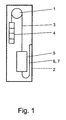
- a traction sheave 1 in the upper Area of a shaft 2 arranged.
- a Set of carrying ropes 3 in simple wrap around the traction sheave 1 led.
- a counterweight 4 directly attached and on the other side a car 5.
- the suspension cable guide and suspension is for the invention insignificant.
- a double Looping be provided or an additional deflection disc and car 5 and counterweight 4 can be in bulk Be hung role.
- the mass of the equalizer is 7 per meter together with the mass of the hanging cable harness 6 per meter therefore 4 times the mass of the supporting rope 3 per meter, with a mass greater than 4 times the balancing effect deteriorates again.
- the compensation line 7 from one or more single strands.
- the Compensating strand 7 For elevators with speeds of up to 8 m / s, the Compensating strand 7 to be designed to be untensioned, beyond he should in a further embodiment of the invention in one Guided guided and optionally by means of a roll tensioning system to be excited.
Landscapes
- Lift-Guide Devices, And Elevator Ropes And Cables (AREA)
Description
- 1
- Treibscheibenantrieb
- 2
- Schacht
- 3
- Tragseilstrang
- 4
- Gegengewicht
- 5
- Fahrkorb
- 6
- Hängekabelstrang
- 7
- Ausgleichsstrang
Claims (6)
- Aufzuganlage mit einem Ausgleich der Tragseilmassen von mittig bis stark außermittig aufgehängten Fahrkörben und mit einem Treibscheibenantrieb, der in einem Schacht, in einer Schachtnische oder in einem separaten Raum untergebracht ist, wobei die Treibscheibe von einem Tragseilstrang einfach, mit oder ohne Ableitscheibe, oder doppelt umschlungen ist, sowie mit einer direkten oder indirekten Aufhängung des Fahrkorbs und eines Gegengewichts, sowie ferner einem Versorgungs- und Funktionssteuer-Hängekabelstrang und einer Massenausgleichsvorrichtung,
dadurch gekenzeichnet,
dass zwischen dem Fahrkorb (5) und einer Schachtwand (2) räumlich neben dem Hängekabelstrang (6) ein Ausgleichsstrang (7) zur Reduzierung der Differenz zwischen der fahrkorbseitigen (5) und gegengewichtsseitigen (4) Belastung des Tragseilstrangs (3) angeordnet ist, dessen Masse je Meter zusammen mit der Hängekabelmasse je Meter das 1,75- bis 4,5-fache der Tragseilmasse je Meter beträgt. - Aufzuganlage nach Anspruch 1,
dadurch gekenzeichnet,
dass die Masse des Ausgleichsstrangs (7) je Meter zusammen mit der Masse des Hängekabelstrangs (6) je Meter das 4-fache der Tragseilmasse je Meter beträgt. - Aufzuganlage nach Anspruch 1 oder 2,
dadurch gekenzeichnet,
dass der Ausgleichsstrang (7) aus einem oder mehreren Strängen besteht. - Aufzuganlage nach einem der Ansprüche 1 - 3,
dadurch gekenzeichnet,
dass der erhöhten Belastung des Tragseilstranges (3) durch eine geeignete Rillenform der Treibscheibe (1) Rechnung getragen ist. - Aufzuganlage nach einem der Ansprüche 1 - 4,
dadurch gekenzeichnet,
dass der Ausgleichsstrang (7) in einer Führung geführt und gegebenenfalls gespannt ist. - Aufzuganlage nach einem der Ansprüche 1 - 5,
dadurch gekenzeichnet,
dass der Ausgleichstrang (7) für Aufzüge mit Fahrgeschwindigkeiten bis ca. 8 m/s ungespannt ausgeführt ist.
Applications Claiming Priority (2)
| Application Number | Priority Date | Filing Date | Title |
|---|---|---|---|
| DE2003105275 DE10305275B4 (de) | 2003-02-07 | 2003-02-07 | Aufzuganlage mit Ausgleich der Tragseilmassen |
| DE10305275 | 2003-02-07 |
Publications (2)
| Publication Number | Publication Date |
|---|---|
| EP1445229A1 EP1445229A1 (de) | 2004-08-11 |
| EP1445229B1 true EP1445229B1 (de) | 2005-01-26 |
Family
ID=32603216
Family Applications (1)
| Application Number | Title | Priority Date | Filing Date |
|---|---|---|---|
| EP20040002416 Expired - Lifetime EP1445229B1 (de) | 2003-02-07 | 2004-02-04 | Aufzuganlage mit Ausgleich der Tragseilmassen |
Country Status (3)
| Country | Link |
|---|---|
| EP (1) | EP1445229B1 (de) |
| DE (1) | DE10305275B4 (de) |
| ES (1) | ES2233920T3 (de) |
Families Citing this family (4)
| Publication number | Priority date | Publication date | Assignee | Title |
|---|---|---|---|---|
| BRPI0419271A (pt) * | 2004-12-29 | 2008-01-22 | Otis Elevator Co | sistema de elevador e método de compensar desequilìbrio de carga em um sistema de elevador |
| WO2007061376A1 (en) | 2005-11-25 | 2007-05-31 | Abb Ab | A method to increase the head rope life for single conveyance friction mine hoists for deep shafts |
| JP5001013B2 (ja) * | 2007-01-10 | 2012-08-15 | 株式会社日立製作所 | エレベータ装置 |
| DE102014113514A1 (de) * | 2014-09-18 | 2016-03-24 | Thyssenkrupp Ag | Aufzuganlage |
Family Cites Families (3)
| Publication number | Priority date | Publication date | Assignee | Title |
|---|---|---|---|---|
| US4716989A (en) * | 1982-08-04 | 1988-01-05 | Siecor Corporation | Elevator compensating cable |
| FI91850C (fi) * | 1993-11-16 | 1994-08-25 | Kone Oy | Kompensaatiojärjestely |
| ATE281395T1 (de) * | 2001-02-27 | 2004-11-15 | Brugg Drahtseil Ag | Anordnung für gewichtsausgleichselemente |
-
2003
- 2003-02-07 DE DE2003105275 patent/DE10305275B4/de not_active Expired - Fee Related
-
2004
- 2004-02-04 ES ES04002416T patent/ES2233920T3/es not_active Expired - Lifetime
- 2004-02-04 EP EP20040002416 patent/EP1445229B1/de not_active Expired - Lifetime
Also Published As
| Publication number | Publication date |
|---|---|
| ES2233920T3 (es) | 2005-06-16 |
| EP1445229A1 (de) | 2004-08-11 |
| DE10305275A1 (de) | 2004-08-26 |
| DE10305275B4 (de) | 2005-05-25 |
Similar Documents
| Publication | Publication Date | Title |
|---|---|---|
| EP1446352B1 (de) | Aufzugssystem | |
| DE69417202T2 (de) | Pufferstruktur | |
| EP2632839B1 (de) | Aufzuganlage | |
| EP1347931A1 (de) | Getriebeloser seilaufzug mit doppelt umschlungenen treibscheibenantrieb | |
| RU2504512C2 (ru) | Лифтовая система и способ ее установки и модификации | |
| US10059565B2 (en) | Reducing elongation of roping or belting of an elevator by pretensioning the roping or belting of the elevator | |
| EP1588977A1 (de) | Einrichtung zur Feinpositionierung der Kabinen einer Mehrdeckkabine für einen Aufzug | |
| EP1818303B1 (de) | Maschinenraumloser Aufzug | |
| DE69936206T2 (de) | Aufzugssystemmit am untererem teil des schachtes angeordnetem antrieb | |
| EP1234796B1 (de) | Anordnung für Gewichtsausgleichselemente | |
| DE102012100791A1 (de) | Zugmittel-Windenvorrichtung | |
| DE10305275B4 (de) | Aufzuganlage mit Ausgleich der Tragseilmassen | |
| DE60315873T2 (de) | Antriebsscheibenaufzug ohne gegengewicht | |
| EP3541737B1 (de) | Seiltrieb mit ummanteltem zugorgan | |
| EP3080029B1 (de) | Aufzuganlage | |
| EP1656318A1 (de) | Aufzug | |
| EP1437322B1 (de) | Treibscheibenaufzug | |
| EP1673301B1 (de) | Antriebssystem für enge triebwerksräume | |
| EP0509404A2 (de) | Fördervorrichtung an Seilförderanlagen zum Antreiben von Förderseilen | |
| DE20219056U1 (de) | Treibscheibenaufzug | |
| DE20320076U1 (de) | Antriebssystem für enge Triebwerksräume | |
| DE10348151A1 (de) | Antriebssystem für enge Triebwerksräume | |
| DE20321733U1 (de) | Gegengewichtsloser Treibscheibenaufzug |
Legal Events
| Date | Code | Title | Description |
|---|---|---|---|
| PUAI | Public reference made under article 153(3) epc to a published international application that has entered the european phase |
Free format text: ORIGINAL CODE: 0009012 |
|
| GRAP | Despatch of communication of intention to grant a patent |
Free format text: ORIGINAL CODE: EPIDOSNIGR1 |
|
| AK | Designated contracting states |
Kind code of ref document: A1 Designated state(s): AT BE BG CH CY CZ DE DK EE ES FI FR GB GR HU IE IT LI LU MC NL PT RO SE SI SK TR |
|
| AX | Request for extension of the european patent |
Extension state: AL LT LV MK |
|
| 17P | Request for examination filed |
Effective date: 20040615 |
|
| GRAS | Grant fee paid |
Free format text: ORIGINAL CODE: EPIDOSNIGR3 |
|
| GRAA | (expected) grant |
Free format text: ORIGINAL CODE: 0009210 |
|
| AK | Designated contracting states |
Kind code of ref document: B1 Designated state(s): ES FR GB IT |
|
| AX | Request for extension of the european patent |
Extension state: AL LT LV MK |
|
| REG | Reference to a national code |
Ref country code: GB Ref legal event code: FG4D Free format text: NOT ENGLISH |
|
| REG | Reference to a national code |
Ref country code: IE Ref legal event code: FG4D Free format text: GERMAN |
|
| AKX | Designation fees paid |
Designated state(s): ES FR GB IT |
|
| GBT | Gb: translation of ep patent filed (gb section 77(6)(a)/1977) |
Effective date: 20050412 |
|
| REG | Reference to a national code |
Ref country code: ES Ref legal event code: FG2A Ref document number: 2233920 Country of ref document: ES Kind code of ref document: T3 |
|
| ET | Fr: translation filed | ||
| PLBE | No opposition filed within time limit |
Free format text: ORIGINAL CODE: 0009261 |
|
| STAA | Information on the status of an ep patent application or granted ep patent |
Free format text: STATUS: NO OPPOSITION FILED WITHIN TIME LIMIT |
|
| 26N | No opposition filed |
Effective date: 20051027 |
|
| PGFP | Annual fee paid to national office [announced via postgrant information from national office to epo] |
Ref country code: ES Payment date: 20090126 Year of fee payment: 6 |
|
| PGFP | Annual fee paid to national office [announced via postgrant information from national office to epo] |
Ref country code: GB Payment date: 20090227 Year of fee payment: 6 |
|
| PGFP | Annual fee paid to national office [announced via postgrant information from national office to epo] |
Ref country code: IT Payment date: 20090223 Year of fee payment: 6 |
|
| PGFP | Annual fee paid to national office [announced via postgrant information from national office to epo] |
Ref country code: FR Payment date: 20090226 Year of fee payment: 6 |
|
| GBPC | Gb: european patent ceased through non-payment of renewal fee |
Effective date: 20100204 |
|
| REG | Reference to a national code |
Ref country code: FR Ref legal event code: ST Effective date: 20101029 |
|
| PG25 | Lapsed in a contracting state [announced via postgrant information from national office to epo] |
Ref country code: FR Free format text: LAPSE BECAUSE OF NON-PAYMENT OF DUE FEES Effective date: 20100301 |
|
| PG25 | Lapsed in a contracting state [announced via postgrant information from national office to epo] |
Ref country code: IT Free format text: LAPSE BECAUSE OF NON-PAYMENT OF DUE FEES Effective date: 20100204 Ref country code: GB Free format text: LAPSE BECAUSE OF NON-PAYMENT OF DUE FEES Effective date: 20100204 |
|
| REG | Reference to a national code |
Ref country code: ES Ref legal event code: FD2A Effective date: 20111118 |
|
| PG25 | Lapsed in a contracting state [announced via postgrant information from national office to epo] |
Ref country code: ES Free format text: LAPSE BECAUSE OF NON-PAYMENT OF DUE FEES Effective date: 20100205 |