EP1445107A1 - Tintenpatrone - Google Patents
Tintenpatrone Download PDFInfo
- Publication number
- EP1445107A1 EP1445107A1 EP02803099A EP02803099A EP1445107A1 EP 1445107 A1 EP1445107 A1 EP 1445107A1 EP 02803099 A EP02803099 A EP 02803099A EP 02803099 A EP02803099 A EP 02803099A EP 1445107 A1 EP1445107 A1 EP 1445107A1
- Authority
- EP
- European Patent Office
- Prior art keywords
- ink
- pressure
- air
- outer case
- ink cartridge
- Prior art date
- Legal status (The legal status is an assumption and is not a legal conclusion. Google has not performed a legal analysis and makes no representation as to the accuracy of the status listed.)
- Withdrawn
Links
Images


Classifications
-
- B—PERFORMING OPERATIONS; TRANSPORTING
- B41—PRINTING; LINING MACHINES; TYPEWRITERS; STAMPS
- B41J—TYPEWRITERS; SELECTIVE PRINTING MECHANISMS, i.e. MECHANISMS PRINTING OTHERWISE THAN FROM A FORME; CORRECTION OF TYPOGRAPHICAL ERRORS
- B41J2/00—Typewriters or selective printing mechanisms characterised by the printing or marking process for which they are designed
- B41J2/005—Typewriters or selective printing mechanisms characterised by the printing or marking process for which they are designed characterised by bringing liquid or particles selectively into contact with a printing material
- B41J2/01—Ink jet
- B41J2/17—Ink jet characterised by ink handling
- B41J2/175—Ink supply systems ; Circuit parts therefor
- B41J2/17503—Ink cartridges
- B41J2/1752—Mounting within the printer
- B41J2/17523—Ink connection
-
- B—PERFORMING OPERATIONS; TRANSPORTING
- B41—PRINTING; LINING MACHINES; TYPEWRITERS; STAMPS
- B41J—TYPEWRITERS; SELECTIVE PRINTING MECHANISMS, i.e. MECHANISMS PRINTING OTHERWISE THAN FROM A FORME; CORRECTION OF TYPOGRAPHICAL ERRORS
- B41J2/00—Typewriters or selective printing mechanisms characterised by the printing or marking process for which they are designed
- B41J2/005—Typewriters or selective printing mechanisms characterised by the printing or marking process for which they are designed characterised by bringing liquid or particles selectively into contact with a printing material
- B41J2/01—Ink jet
- B41J2/17—Ink jet characterised by ink handling
- B41J2/175—Ink supply systems ; Circuit parts therefor
- B41J2/17503—Ink cartridges
- B41J2/17506—Refilling of the cartridge
- B41J2/17509—Whilst mounted in the printer
-
- B—PERFORMING OPERATIONS; TRANSPORTING
- B41—PRINTING; LINING MACHINES; TYPEWRITERS; STAMPS
- B41J—TYPEWRITERS; SELECTIVE PRINTING MECHANISMS, i.e. MECHANISMS PRINTING OTHERWISE THAN FROM A FORME; CORRECTION OF TYPOGRAPHICAL ERRORS
- B41J2/00—Typewriters or selective printing mechanisms characterised by the printing or marking process for which they are designed
- B41J2/005—Typewriters or selective printing mechanisms characterised by the printing or marking process for which they are designed characterised by bringing liquid or particles selectively into contact with a printing material
- B41J2/01—Ink jet
- B41J2/17—Ink jet characterised by ink handling
- B41J2/175—Ink supply systems ; Circuit parts therefor
- B41J2/17503—Ink cartridges
- B41J2/17513—Inner structure
-
- B—PERFORMING OPERATIONS; TRANSPORTING
- B41—PRINTING; LINING MACHINES; TYPEWRITERS; STAMPS
- B41J—TYPEWRITERS; SELECTIVE PRINTING MECHANISMS, i.e. MECHANISMS PRINTING OTHERWISE THAN FROM A FORME; CORRECTION OF TYPOGRAPHICAL ERRORS
- B41J2/00—Typewriters or selective printing mechanisms characterised by the printing or marking process for which they are designed
- B41J2/005—Typewriters or selective printing mechanisms characterised by the printing or marking process for which they are designed characterised by bringing liquid or particles selectively into contact with a printing material
- B41J2/01—Ink jet
- B41J2/17—Ink jet characterised by ink handling
- B41J2/175—Ink supply systems ; Circuit parts therefor
- B41J2/17503—Ink cartridges
- B41J2/17556—Means for regulating the pressure in the cartridge
Definitions
- the ink cartridge is so constructed that a deformable ink pack under external pressure is housed in an outer case which can hold air-tightness, exposing only an ink outlet of the ink pack. Pressurized air is supplied to the outer case from an air source for pressure in which the air pressure is adjusted at a constant pressure in advance, and the ink pack is pressurized by the air pressure thereby to supply ink to the recording head.
- an obj ect of the present invention is to provide an ink cartridge having a pressure adjusting function with which the air force forpressurizing an inkpackcanbe set independently in the respective ink cartridges without depending on the air pressure supplied from the air source for pressure.
- Another object of the invention is to provide an ink cartridge in which the ink pack can be pressurized so that ink discharging amount is suitable for printing regardless of ink remaining amount.
- the setting value of the pressure adjusting unit can be set to an optimum value for each ink cartridge, and the ink pack can be pressurized in an optimum state regardless of air pressure provided from the pressurized air inlet, namely, the pressure of the air source for pressure.
- the pressure adjusting unit comprises an urging unit for adjusting the setting value; an elastic pressure reception plate which is displaced when one surface is pressed by the urging unit, and when the other surface receives the pressure in the space of the outer case; and an air communicating hole forming member which communicates to the atmosphere and is sealed by the elastic pressure reception plate.
- the pressure adjusting unit can be made as small as possible, and a general-purpose differential pressure valve can be applied.
- ink can be supplied to the recording head in an optimum state.
- the urging unit is provided with a unit which changes its urging force according to the ink remaining amount of the ink pack.
- ink discharging amount suitable for printing can be supplied to the recording head.
- the pressure adjusting unit comprises a deformation region which is formed at a partial region of the outer case and is elastically deformable by the air pressure; and a valve member which opens or closes according to displacement of the deformation region thereby to communicate the space in the outer case with the atmosphere.
- the structure canbe simplified, the setting value of the pressure adjusting unit can be set to an optimum value for each ink cartridge, and the ink pack can be pressurized in an optimum state regardless of air pressure from the pressurized air inlet.
- valve member is arranged so that the urging unit seals the air-communicating hole formed at the deformation region, and an operating rod for pressing the valve member is exposed from the air-communicating hole.
- dead space of the ink cartridge can be utilized effectively, and a position for providing the deformation region can be selected more freely.
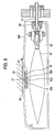
- Fig. 1 shows one embodiment of an ink jet recording apparatus of the invention, in which a carriage 1 is guided by a scan guide member 4 through a timing belt 3 driven by a carriage motor 2 in a longitudinal direction of a sheet feeding member 5, that is, in a main scanning direction that is a width direction of a recording sheet.
- a not-shown ink jet recording head which can eject ink of each color as a liquid droplet is provided.
- sub-tanks 7B, 7C, 7M, 7Y for supplying ink to the recording head are mounted.
- ink cartridges 9B, 9C, 9M, 9Y are detachably arranged.
- the ink cartridges 9B, 9C, 9M, 9Y are respectively connected through tubes 10 to the sub-tanks 7B, 7C, 7M, 7Y, and supply ink to the recording head through the respective sub-tanks 7B, 7C, 7M, 7Y.
- the respective ink cartridges 9B, 9C, 9M, 9Y are connected at space of their outer cases to respective individual air pump 13B. 13C, 13M, and 13Y by tubes 14, whereby ink is discharged to the sub-tanks by pressurized force of pressurized air.
- a capping unit 11 which can seal a nozzle-forming surface of the recording head, and a wiping member 12 which is adjacent to the. capping unit 11 and made of elastic material such as rubber are arranged.
- Figs. 2 to 4B show one embodiment of the ink cartridge.
- the ink cartridge comprises an outer case 20 and an ink pack 21, and the ink pack 21 is housed in the outer case 20 so that an ink outlet pipe 22 provided for the ink pack 21 is exposed from a center portion of one side surface of the case 20.
- the outer case 20 comprises a container body 20a and a lid member 20b, and includes a pressurized air inlet 23 for taking in the pressurized air at an end region of one side surface where the ink outlet pipe 22 is exposed.
- the ink pack 21, as known, is made of liquid-tight film which can deform upon reception of air pressure of the pressurized air, and stores ink therein. Further, a cylindrical stopper 24 having a permeable pore is attached to a leading end of the ink outlet pipe 22 in order to liquid-tightly come into contact with the periphery of an ink inlet pipe 41.
- the pressurized air inlet 23 is connected to a space 25 of the outer case 20 through a pressure adjusting unit 30, and an air inlet passage is constituted so that air pressure suitable to discharge ink from the ink pack 21 is applied to the ink pack 21.
- the pressure adjusting unit 30 is so constructed that an elastic pressure reception plate 31 formed of elastic material such as rubber having air-tightness and elasticity, namely, a diaphragm in this embodiment for example, are housed in an air communicating hole forming member 33, namely, a case in this embodiment so that a constant pressure is applied onto one surface of the elastic pressure reception plate 31 by an elasticity applying unit 32 such as a spring. Further, the pressure adjusting unit 30 is so constructed that an air communicating hole 34 is formed in a position of the air communicating hole forming member 33 opposed to a center region of the elastic pressure reception plate 31, and that a communicating hole 35 is formed on a side of the air communicating hole forming member 33 so as to communicate with the space 25 of the outer case. In this embodiment, a permeable pore 36 is formed in a position of the air-communicating hole forming member 33 opposed to the pressurized air inlet 23.
- the elastic pressure reception plate 31 has a convex portion 31a at its region opposed to the air-communicating hole 34, and the convex portion 31a seals the air-communicating hole 34 surely.
- Reference numeral 37 represents a packing for securing air-tightness between the air-communicating hole forming member 33 and the outer case 20.
- a cartridge holder is provided, and it includes an ink inlet pipe 41 formed fittably to the ink outlet pipe 22 of the ink cartridge on its wall surface 40 opposed to the ink outlet pipe 22 of the ink cartridge 9, and a pressurized air outlet pipe 42 arranged fittably to the pressurized air inlet 23.
- the ink inlet pipe 41 is connected to each sub-tank 7B, 7C, 7M, and 7Y through the tube passage 10, and the pressurized air outlet pipe 42 is connected to an discharge port of each air pump 13B, 13C, 13M, 13Y (Fig. 1).
- the ink outlet pipe 22 of the ink cartridge 9 firstly fits to the ink inlet pipe 41 on the recording apparatus side, and then the pressurized air inlet 23 of the ink cartridge 9 fits to the pressurized air outlet pipe 42 air-tightly.
- the pressurized air inlet 23 of the ink cartridge 9 fits to the pressurized air outlet pipe 42 air-tightly.
- the air pumps 13B, 13C, 13M, and 13Y operate and the pressurized air flow through the pressurized air inlet 23 and the permeable pore 36 in the space 25 of the outer case 20.
- the pressurized air flows in the space of the outer case 20 through the communicating hole 35 of the air-communicating hole forming member 33 constituting the pressure adjusting unit 30. Therefore, when the fluid resistance of the communicating hole 35 is used as a flowing passage resistance forming portion appropriately set, even in case that air of excessive pressure is supplied at the carriage attaching time, the elastic pressure reception plate 31 firstly receives its pressure and retreats thereby to open the air communicating hole 34, relax sharp pressure change of the outer case 20, and prevent the ink pack and the ink supplying passage from receiving the sharp pressure change, so that break can be prevented.
- the pressure of the space in the outer case 20 is roughly atmospheric pressure, and the elastic pressure reception plate 31 seals the air communicating hole 34 by the urging force of the urging unit 32. Therefore, all the pressurized air flows in the space 25 of the outer case 20.
- the elastic pressure reception plate 31 retreats from the air-communicating hole 34 against the urging unit 32.
- a part of air in the outer case 20 flows out from the air communicating hole 34 and the pressure in the outer case 20 decreases.
- the pressurized air inlet 23 of the ink cartridge 9 comes out of the pressurized air outlet pipe 42. Therefore, the air in the space 25 of the outer case 20 is released to the atmosphere through the permeable pore 36 from the pressurized air inlet 23, and the pressure in the space 25 decreases up to the atmospheric pressure. Next, the ink outlet pipe 22 of the ink cartridge 9 comes out of the ink inlet pipe 41 of the recording apparatus.
- the movable member 24b seals the through-hole 24a of the stopper 24, so that leakage of ink and inflow of air into the ink pack 21 can be prevented. Further, in a state where the ink cartridge is attached into the holder, the movable member 24b retreats, so that ink flows into the ink inlet pipe 41 from the through-hole 41a of the ink inlet pipe 41.
- the backside of the elastic pressure reception plate 31 constituting the pressure adjusting unit 30, that is, the space in which the urging unit 32 is housed is sealed.
- a permeable pore 33a which interrupts the space 25 of the outer case 20 through a packing 26, and communicates with a permeable pore 27 of the outer case 20 to communicate with the atmosphere is provided, the fluctuation of the set pressure of the elastic pressure reception plate 31 caused by increase of temperature can be prevented, so that ink can be stably-supplied.
- the valve member 50 includes a convex portion 50a that can seal the through-hole 29 at a region opposed to the through-hole 29.
- An urging unit; the valve member 50 in this embodiment is composed of an elastic member such as rubber, and displaces the convexportion 50a usually so as to come into contact with the through-hole 29.
- Surroundings of the valve member 50 are fixed by adhesive and a frame body 52, and the afore-mentioned operation rod 51 is provided for the convex portion 50a. Therefore, in this embodiment, the deforming region of the outer case 20, the valve member 50, and the operation rod 51 constitutes the afore-mentioned pressure adjusting unit.
- a holder constituting the recording apparatus has, at a region opposed to the operation rod 51 in a state where the ink cartridge 9 is attached, a gap G1 which makes the elastic deformation of the outer case possible, and a partition wall 43 for receiving displacement of the operation rod 51.
- the converx portion 50a of the valve member 50 separates from the through-hole 29, the space 25 is released to the atmosphere through the through-hole 29, a permeable pore 50b, and a permeable pore 52a, and a part of the pressurized air in the space flows out from the through-hole 29, so that the pressure in the outer case 20 decreases.
- Expansion degree of the outer case is reduced by the decrease of pressure in the space 25, the operation rod 51 separates from the partition wall 43, and the valve member 50 seals the through-hole 29. Sequentially, the pressure in the space 25 is detected as displacement of the outer case 20, and the valve member 50 is connected to or disconnected from the through-hole 29 according to this displacement, whereby the pressure in the space 25 of the outer case 20 is kept at pressure suitable for ink supply.
- the valve member 50 is arranged at the region which can deform elastically.
- a link mechanism such as a lever is coupled to the operation rod 51 to transmit the displacement of the operation rod 51 to another portion
- the valve 50 can be arranged in another position.
- the outer case 20 is so constituted so that it can deform elastically, also in case that a window is formed in the outer case 20 and this window is sealed with an elastic plate, the similar effect is obtained.
- the pressure is adjusted to air pressure suitable for each cartridge by the pressure adjusting unit of each cartridge, and it can be readjusted by the pressure adjusting unit according to difference in height among the ink cartridges and length of the ink supply tube, so that unevenness and fluctuation in ink current due to the pressure from the pump or the like can be reduced.
- the various kinds of cartridges can be attached.
- the regular value of the pressure adjusting unit can be adjusted by appropriately adjusting elasticity of the elastic pressure reception plate 31 and the urging force of the urging unit 32.
- the ink pack is pressurized at a constant pressure.
- the pressing force maybe changed according to the ink remaining amount.
- a pressure adjusting unit is so constituted as to change the above pressing force.
- volume of ink pack that is, the amount of remaining ink is detected by a detection plate 60, and pressing force of an elastic press reception plate 31 is changed according to the displacement of the detection plate 60.
- a first permanent magnet 61 is attached on the backside of the elastic pressure reception plate 31, and a second permanent magnet 62 is attached at a leading end of the detection plate 60.
- the detection plate 60 in case that the ink remaining amount becomes small and relatively the pressing force decreases, the detection plate 60 is displaced, the second permanent magnet 62 attached to this detection plate 60 approaches the magnet 61 of the elastic pressure reception plate 31 as shown by reference numeral 62' in Fig. 10.
- repulsion force becomes strong between the two magnets and the permanent magnet 61 moves toward the elastic pressure reception plate 31, and the pressing force of the elastic pressure reception plate 31 through a spring 32 increases, so that pressure in a space of an outer case 20 increases.
- ink canbe supplied at a constant ink current, so that deterioration of printing quality caused by shortage of ink supply can be prevented and ink in the ink pack can be supplied to a recording head to the last.
- Figs. 11A and 11B to 12A and 12B show one embodiment of the sub-tank used as an intermediate unit in case that ink in the ink cartridge is supplied to the recording head.
- a base body 70 includes on its surface an ink inlet 71 connected to the ink cartridge, and ink outlet 72 from which ink is supplied to the recording head. Further, the base body 70 includes in the center a recess portion 73' for forming an ink storing chamber 73.
- the ink storing chamber 73 is so structured that the recess portion 73' is sealed by a film 74 which can elastically deform according to pressure change due to ink consumption in the recording head.
- the film 74 in order to efficiently transmit displacement of the film 74 to an operation rod described later, is provided with a backing material 75 made of plate in the center thereof so that an elastically deformable region leaves in circumference of the film 74 annularly, whereby rigidity is heightened.
- the region of the backing material 75 is formed thicker, whereby the backing material 75 can be constituted integrally with the film 74.
- a groove 76' communicating with the ink outlet 72 is formed, and sealed by a film, i.e., the film 74 forming the ink storing chamber in this embodiment thereby to form an ink discharging passage 76.
- a communicating hole 76a of the ink discharging passage 74 with the ink storing chamber 73 is located at the top portion of the ink storing chamber 73 when the sub-tank is set.
- Reference numeral 85 represents a lid member for seal
- reference numeral 86 is a ring-shaped elastic seal member which is arranged around the communicating hole 81a and with which the valve member comes into contact.
- ink in the ink storing chamber 73 flows into the recording head. Since the communicating hole 81a is sealed by the valve member 83 in the present state, the ink in the ink storing chamber 73 is supplied while the film 74 is being displaced on the valve housing chamber side. When the pressure in the ink storing chamber 73 becomes lower than the set pressure by the urging unit 82, the operation rod 84 is pressed by the displacement of the film 74 against the urging force of the urging unit 82 and separates from the communicating hole 81a.
- the ink in the ink cartridge flows into the ink storing chamber 73 through the valve housing chamber 80, the pressure in the ink storing chamber 73 increases, and the film 74 moves outward.
- the valve member 83 seals the communicating hole 81a thereby to stop ink supply to the ink storing chamber 73.
- valve opening pressure of the valve member is set by the urging unit 82 composed of the spring, regardless of posture of sub-tank, and regardless of inertial force due to the movement of carriage, the ink can be supplied to the recording head while the negative pressure state is being kept.
- the setting value of the pressure adjusting unit is set to an optimum value for each ink cartridge, whereby ink can be supplied to the recording head in an optimum state regardless of fluid resistance of the ink supply passage from the ink cartridge to the recording head, and regardless of difference in height between the ink. cartridges, so that printing having high quality can be performed.
Applications Claiming Priority (3)
| Application Number | Priority Date | Filing Date | Title |
|---|---|---|---|
| JP2001345828 | 2001-11-12 | ||
| JP2001345828 | 2001-11-12 | ||
| PCT/JP2002/011649 WO2003041963A1 (fr) | 2001-11-12 | 2002-11-08 | Cartouche d'encre |
Publications (2)
| Publication Number | Publication Date |
|---|---|
| EP1445107A1 true EP1445107A1 (de) | 2004-08-11 |
| EP1445107A4 EP1445107A4 (de) | 2005-06-29 |
Family
ID=19159105
Family Applications (1)
| Application Number | Title | Priority Date | Filing Date |
|---|---|---|---|
| EP02803099A Withdrawn EP1445107A4 (de) | 2001-11-12 | 2002-11-08 | Tintenpatrone |
Country Status (8)
| Country | Link |
|---|---|
| US (2) | US7086722B2 (de) |
| EP (1) | EP1445107A4 (de) |
| JP (1) | JPWO2003041963A1 (de) |
| KR (1) | KR100518205B1 (de) |
| CN (1) | CN1254378C (de) |
| CA (1) | CA2434639A1 (de) |
| TW (1) | TW561111B (de) |
| WO (1) | WO2003041963A1 (de) |
Cited By (1)
| Publication number | Priority date | Publication date | Assignee | Title |
|---|---|---|---|---|
| EP1920932A1 (de) | 2006-10-31 | 2008-05-14 | Brother Kogyo Kabushiki Kaisha | Tintenkartuschen und Tintenzufuhrsysteme |
Families Citing this family (20)
| Publication number | Priority date | Publication date | Assignee | Title |
|---|---|---|---|---|
| US7086722B2 (en) * | 2001-11-12 | 2006-08-08 | Seiko Epson Corporation | Ink cartridge |
| JP2004268575A (ja) * | 2003-02-19 | 2004-09-30 | Seiko Epson Corp | 液体貯留手段及び液体噴射装置 |
| US7384133B2 (en) | 2003-08-08 | 2008-06-10 | Seiko Epson Corporation | Liquid container capable of maintaining airtightness |
| JP4478927B2 (ja) * | 2004-03-10 | 2010-06-09 | セイコーエプソン株式会社 | 液体容器 |
| JP2007253457A (ja) * | 2006-03-23 | 2007-10-04 | Seiko Epson Corp | 液体加圧方法、液体吐出装置、及び液体カートリッジ |
| JP5134212B2 (ja) * | 2006-06-08 | 2013-01-30 | ブラザー工業株式会社 | インクカートリッジ |
| JP2008161750A (ja) * | 2006-12-27 | 2008-07-17 | Seiko Epson Corp | 液滴吐出装置、及びデバイスの製造方法 |
| JP4605178B2 (ja) * | 2007-04-23 | 2011-01-05 | セイコーエプソン株式会社 | 液体収容体 |
| CA2638280A1 (en) * | 2007-07-24 | 2009-01-24 | Richard H. Berg | Wide format ink cartridge |
| JP5277622B2 (ja) * | 2007-11-30 | 2013-08-28 | ブラザー工業株式会社 | インク供給装置およびカートリッジ収容装置 |
| JP5769384B2 (ja) * | 2010-04-20 | 2015-08-26 | キヤノン株式会社 | インクカートリッジおよびインクジェット記録装置 |
| US20110279583A1 (en) * | 2010-05-17 | 2011-11-17 | Silverbrook Research Pty Ltd | Liquid container with passive capacity state sensing |
| RU2558616C2 (ru) * | 2013-05-07 | 2015-08-10 | Российская академия наук Федеральное государственное бюджетное учреждение науки Институт систем обработки изображений Российской академии наук (ИСОИ РАН) | Способ подсветки дисплея с использованием вторичной оптики и светорассеивающей подложки, устройство для подсветки дисплея |
| JP2016187876A (ja) * | 2015-03-30 | 2016-11-04 | セイコーエプソン株式会社 | カートリッジ、カートリッジユニット、及び、液体噴射システム |
| CN108688331B (zh) * | 2015-06-19 | 2019-12-10 | 工正集团有限公司 | 一种适用于墨盒的控制气压平衡和返流平衡的装置 |
| CN106256548B (zh) * | 2015-06-19 | 2018-06-26 | 珠海东威电脑耗材有限公司 | 一种带有密封变形装置的无海绵墨盒装置 |
| CN106313901B (zh) * | 2015-06-19 | 2018-08-03 | 中山市兴发电子科技有限公司 | 一种适用于墨盒的气压平衡装置 |
| US20220143980A1 (en) * | 2019-07-30 | 2022-05-12 | Hewlett-Packard Development Company, L.P. | Fluid ejection head service with non-wetting layer |
| KR102589497B1 (ko) | 2019-07-30 | 2023-10-13 | 휴렛-팩커드 디벨롭먼트 컴퍼니, 엘.피. | 균일한 프린트 헤드면 코팅 |
| JP2022155053A (ja) * | 2021-03-30 | 2022-10-13 | キヤノン株式会社 | 液体収容容器 |
Citations (6)
| Publication number | Priority date | Publication date | Assignee | Title |
|---|---|---|---|---|
| US4598303A (en) * | 1984-11-28 | 1986-07-01 | Tektronix, Inc. | Method and apparatus for operating an ink jet head of an ink jet printer |
| EP0562717A1 (de) * | 1992-02-24 | 1993-09-29 | Canon Kabushiki Kaisha | Ventilmechanismus für Flüssigkeitsbehälter in einer Flüssigkeitsaufzeichnungsvorrichtung |
| US5917523A (en) * | 1990-01-12 | 1999-06-29 | Hewlett-Packard Company | Refill method for ink-jet print cartridge |
| EP0968831A1 (de) * | 1998-06-29 | 2000-01-05 | Imaje S.A. | Tintenkreis, Tintenstrahldrucker und Verpackungsmaschine oder Fördereinrichtung die einen solchen Tintenkreis verwendet |
| EP1142713A2 (de) * | 1999-11-05 | 2001-10-10 | Seiko Epson Corporation | Aufzeichnungsgerät des tintenstrahltyps und verfahren zur tintenversorgung für den untertank mittels desselben gertes und verfahren zur kontrolle der dem untertank zugeführten tintenmenge mittels desselben gerätes |
| US20010038405A1 (en) * | 2000-04-11 | 2001-11-08 | Taku Ishizawa | Ink cartridge for recording apparatus |
Family Cites Families (29)
| Publication number | Priority date | Publication date | Assignee | Title |
|---|---|---|---|---|
| JPS5945160A (ja) * | 1982-09-07 | 1984-03-13 | Konishiroku Photo Ind Co Ltd | インクジエツト記録装置 |
| US4558326A (en) * | 1982-09-07 | 1985-12-10 | Konishiroku Photo Industry Co., Ltd. | Purging system for ink jet recording apparatus |
| US4604633A (en) * | 1982-12-08 | 1986-08-05 | Konishiroku Photo Industry Co., Ltd | Ink-jet recording apparatus |
| JPS60198256A (ja) * | 1984-03-21 | 1985-10-07 | Konishiroku Photo Ind Co Ltd | インク貯蔵装置 |
| EP0660092B1 (de) * | 1987-04-15 | 2003-07-30 | Canon Kabushiki Kaisha | Ein Flüssigkeitsrestmengendetektor und ein Flüssigkeitseinspritzregistriergerät mit diesem Detektor |
| US5526030A (en) * | 1992-10-05 | 1996-06-11 | Hewlett-Packard Company | Pressure control apparatus for an ink pen |
| JP2994740B2 (ja) * | 1990-11-30 | 1999-12-27 | 株式会社ユニフローズ | 脱気装置 |
| US6264314B1 (en) * | 1991-05-27 | 2001-07-24 | Seiko Epson Corporation | Ink cartridge for ink jet recording apparatus |
| US5359353A (en) * | 1991-06-19 | 1994-10-25 | Hewlett-Packard Company | Spring-bag printer ink cartridge with volume indicator |
| JP3005104B2 (ja) | 1992-02-24 | 2000-01-31 | キヤノン株式会社 | 液体貯蔵容器、該液体貯蔵容器を有する記録ヘッドユニット、及び該液体貯蔵容器を搭載した記録装置 |
| US5278584A (en) * | 1992-04-02 | 1994-01-11 | Hewlett-Packard Company | Ink delivery system for an inkjet printhead |
| US5754207A (en) | 1992-08-12 | 1998-05-19 | Hewlett-Packard Company | Volume indicating ink reservoir cartridge system |
| JPH08174860A (ja) * | 1994-10-26 | 1996-07-09 | Seiko Epson Corp | インクジェットプリンタ用インクカートリッジ |
| US5825387A (en) | 1995-04-27 | 1998-10-20 | Hewlett-Packard Company | Ink supply for an ink-jet printer |
| US6074050A (en) | 1997-12-03 | 2000-06-13 | Hewlett-Packard Company | Method and apparatus for venting an ink container |
| US6585359B1 (en) | 1997-06-04 | 2003-07-01 | Hewlett-Packard Development Company, L.P. | Ink container providing pressurized ink with ink level sensor |
| US5992975A (en) | 1997-06-04 | 1999-11-30 | Hewlett-Packard Company | Electrical interconnect for an ink container |
| US6116723A (en) * | 1998-03-09 | 2000-09-12 | Hewlett-Packard | Low cost pressurizable ink container |
| US6186620B1 (en) * | 1999-02-12 | 2001-02-13 | Industrial Technology Research Institute | Ink pressure control apparatus for ink-jet pens |
| JP3467685B2 (ja) | 2000-01-21 | 2003-11-17 | セイコーエプソン株式会社 | インクジェット式記録装置および同装置におけるサブタンクへのインク補給制御方法 |
| JP2001205819A (ja) | 2000-01-31 | 2001-07-31 | Seiko Epson Corp | インクカートリッジおよびこれを用いるインクジェット式記録装置 |
| ATE269788T1 (de) | 1999-11-05 | 2004-07-15 | Seiko Epson Corp | Tintenstrahlaufzeichnungsvorrichtung |
| JP2001212974A (ja) | 2000-02-01 | 2001-08-07 | Seiko Epson Corp | インクジェット式記録装置および同装置におけるサブタンクへのインク補給方法 |
| JP2001162834A (ja) * | 1999-12-13 | 2001-06-19 | Canon Inc | インク供給装置およびインク供給方法 |
| JP2002001988A (ja) * | 2000-04-18 | 2002-01-08 | Canon Aptex Inc | インクタンクおよびインクジェットカートリッジ |
| JP2002001978A (ja) * | 2000-06-19 | 2002-01-08 | Canon Inc | 液体補給方法およびその装置ならびに画像形成装置 |
| WO2002028648A1 (en) * | 2000-10-06 | 2002-04-11 | Nu-Kote International, Inc. | Diaphragm/check valve used in inkjet cassette to air removal for extended life storage |
| TW505572B (en) * | 2000-10-20 | 2002-10-11 | Internat United Technoloy Co L | Ink container with pressure regulation device |
| US7086722B2 (en) * | 2001-11-12 | 2006-08-08 | Seiko Epson Corporation | Ink cartridge |
-
2002
- 2002-11-08 US US10/466,180 patent/US7086722B2/en not_active Expired - Fee Related
- 2002-11-08 EP EP02803099A patent/EP1445107A4/de not_active Withdrawn
- 2002-11-08 CA CA002434639A patent/CA2434639A1/en not_active Abandoned
- 2002-11-08 CN CNB028036301A patent/CN1254378C/zh not_active Expired - Fee Related
- 2002-11-08 KR KR10-2003-7009327A patent/KR100518205B1/ko not_active IP Right Cessation
- 2002-11-08 JP JP2003543826A patent/JPWO2003041963A1/ja active Pending
- 2002-11-08 WO PCT/JP2002/011649 patent/WO2003041963A1/ja active IP Right Grant
- 2002-11-11 TW TW091133050A patent/TW561111B/zh not_active IP Right Cessation
-
2006
- 2006-05-31 US US11/443,128 patent/US7506972B2/en not_active Expired - Fee Related
Patent Citations (6)
| Publication number | Priority date | Publication date | Assignee | Title |
|---|---|---|---|---|
| US4598303A (en) * | 1984-11-28 | 1986-07-01 | Tektronix, Inc. | Method and apparatus for operating an ink jet head of an ink jet printer |
| US5917523A (en) * | 1990-01-12 | 1999-06-29 | Hewlett-Packard Company | Refill method for ink-jet print cartridge |
| EP0562717A1 (de) * | 1992-02-24 | 1993-09-29 | Canon Kabushiki Kaisha | Ventilmechanismus für Flüssigkeitsbehälter in einer Flüssigkeitsaufzeichnungsvorrichtung |
| EP0968831A1 (de) * | 1998-06-29 | 2000-01-05 | Imaje S.A. | Tintenkreis, Tintenstrahldrucker und Verpackungsmaschine oder Fördereinrichtung die einen solchen Tintenkreis verwendet |
| EP1142713A2 (de) * | 1999-11-05 | 2001-10-10 | Seiko Epson Corporation | Aufzeichnungsgerät des tintenstrahltyps und verfahren zur tintenversorgung für den untertank mittels desselben gertes und verfahren zur kontrolle der dem untertank zugeführten tintenmenge mittels desselben gerätes |
| US20010038405A1 (en) * | 2000-04-11 | 2001-11-08 | Taku Ishizawa | Ink cartridge for recording apparatus |
Non-Patent Citations (1)
| Title |
|---|
| See also references of WO03041963A1 * |
Cited By (2)
| Publication number | Priority date | Publication date | Assignee | Title |
|---|---|---|---|---|
| EP1920932A1 (de) | 2006-10-31 | 2008-05-14 | Brother Kogyo Kabushiki Kaisha | Tintenkartuschen und Tintenzufuhrsysteme |
| US7946696B2 (en) | 2006-10-31 | 2011-05-24 | Brother Kogyo Kabushiki Kaisha | Ink cartridges and ink supply systems |
Also Published As
| Publication number | Publication date |
|---|---|
| KR20040020877A (ko) | 2004-03-09 |
| EP1445107A4 (de) | 2005-06-29 |
| KR100518205B1 (ko) | 2005-10-04 |
| WO2003041963A1 (fr) | 2003-05-22 |
| US7506972B2 (en) | 2009-03-24 |
| CA2434639A1 (en) | 2003-05-22 |
| US20060232648A1 (en) | 2006-10-19 |
| CN1484583A (zh) | 2004-03-24 |
| TW561111B (en) | 2003-11-11 |
| JPWO2003041963A1 (ja) | 2005-03-03 |
| US20040239734A1 (en) | 2004-12-02 |
| TW200300114A (en) | 2003-05-16 |
| CN1254378C (zh) | 2006-05-03 |
| US7086722B2 (en) | 2006-08-08 |
Similar Documents
| Publication | Publication Date | Title |
|---|---|---|
| US7506972B2 (en) | Ink cartridge | |
| CA2565475C (en) | Ink tank, printing head and inkjet printing apparatus | |
| EP1445105B1 (de) | Flüssigkeitsinjektionsvorrichtung | |
| CN1853937B (zh) | 液体供应系统的制造方法及液体供应系统 | |
| EP1120259A2 (de) | Tintenstrahlaufzeichnungsgerät | |
| EP1398156A2 (de) | Tintenpatrone und Verfahren zur Regelung des Durchflusses einer Flüssigkeit | |
| US7992981B2 (en) | Liquid supply device and liquid ejecting apparatus | |
| US8356890B2 (en) | Pressure regulating valve for inkjet printer | |
| JP5309796B2 (ja) | 液体供給装置及び液体噴射装置 | |
| EP1698468A1 (de) | Ventilvorrichtung, druckminderventil, schlitten, flüssigkeitsspritzvorrichtung und verfahren zur herstellung einer ventilvorrichtung | |
| US8061825B2 (en) | Liquid cartridge | |
| US6666549B2 (en) | Ink-jet recording apparatus and ink supply method therein | |
| JP5131046B2 (ja) | 液体供給装置及び印刷装置 | |
| JP4645070B2 (ja) | 弁装置及び液体噴射装置 | |
| JP5007586B2 (ja) | バルブユニット及び流体噴射装置 | |
| JP2005225216A (ja) | 液体噴射装置 | |
| JP2003311997A (ja) | インクジェット式記録装置およびそのインク供給方法 | |
| KR100832590B1 (ko) | 잉크 탱크, 인쇄 헤드 및 잉크젯 인쇄 장치 | |
| JP2005193482A (ja) | 液体噴射装置 | |
| JP2005199526A (ja) | 液体噴射装置及び液体噴射装置の駆動方法 | |
| JP2005199527A (ja) | 液体噴射ヘッドのクリーニング方法及び液体噴射装置のクリーニング方法 |
Legal Events
| Date | Code | Title | Description |
|---|---|---|---|
| PUAI | Public reference made under article 153(3) epc to a published international application that has entered the european phase |
Free format text: ORIGINAL CODE: 0009012 |
|
| 17P | Request for examination filed |
Effective date: 20030714 |
|
| AK | Designated contracting states |
Kind code of ref document: A1 Designated state(s): AT BE BG CH CY CZ DE DK EE ES FI FR GB GR IE IT LI LU MC NL PT SE SK TR |
|
| REG | Reference to a national code |
Ref country code: HK Ref legal event code: DE Ref document number: 1067594 Country of ref document: HK |
|
| A4 | Supplementary search report drawn up and despatched |
Effective date: 20050517 |
|
| 17Q | First examination report despatched |
Effective date: 20071221 |
|
| GRAP | Despatch of communication of intention to grant a patent |
Free format text: ORIGINAL CODE: EPIDOSNIGR1 |
|
| STAA | Information on the status of an ep patent application or granted ep patent |
Free format text: STATUS: THE APPLICATION IS DEEMED TO BE WITHDRAWN |
|
| 18D | Application deemed to be withdrawn |
Effective date: 20100112 |
|
| REG | Reference to a national code |
Ref country code: HK Ref legal event code: WD Ref document number: 1067594 Country of ref document: HK |