EP1443296A1 - Pyromechanisches Trennelement - Google Patents
Pyromechanisches Trennelement Download PDFInfo
- Publication number
- EP1443296A1 EP1443296A1 EP04001764A EP04001764A EP1443296A1 EP 1443296 A1 EP1443296 A1 EP 1443296A1 EP 04001764 A EP04001764 A EP 04001764A EP 04001764 A EP04001764 A EP 04001764A EP 1443296 A1 EP1443296 A1 EP 1443296A1
- Authority
- EP
- European Patent Office
- Prior art keywords
- locking
- housing
- groove
- force limiting
- limiting element
- Prior art date
- Legal status (The legal status is an assumption and is not a legal conclusion. Google has not performed a legal analysis and makes no representation as to the accuracy of the status listed.)
- Granted
Links
Images


Classifications
-
- F—MECHANICAL ENGINEERING; LIGHTING; HEATING; WEAPONS; BLASTING
- F42—AMMUNITION; BLASTING
- F42B—EXPLOSIVE CHARGES, e.g. FOR BLASTING, FIREWORKS, AMMUNITION
- F42B3/00—Blasting cartridges, i.e. case and explosive
- F42B3/006—Explosive bolts; Explosive actuators
-
- F—MECHANICAL ENGINEERING; LIGHTING; HEATING; WEAPONS; BLASTING
- F15—FLUID-PRESSURE ACTUATORS; HYDRAULICS OR PNEUMATICS IN GENERAL
- F15B—SYSTEMS ACTING BY MEANS OF FLUIDS IN GENERAL; FLUID-PRESSURE ACTUATORS, e.g. SERVOMOTORS; DETAILS OF FLUID-PRESSURE SYSTEMS, NOT OTHERWISE PROVIDED FOR
- F15B15/00—Fluid-actuated devices for displacing a member from one position to another; Gearing associated therewith
- F15B15/19—Pyrotechnical actuators
-
- F—MECHANICAL ENGINEERING; LIGHTING; HEATING; WEAPONS; BLASTING
- F15—FLUID-PRESSURE ACTUATORS; HYDRAULICS OR PNEUMATICS IN GENERAL
- F15B—SYSTEMS ACTING BY MEANS OF FLUIDS IN GENERAL; FLUID-PRESSURE ACTUATORS, e.g. SERVOMOTORS; DETAILS OF FLUID-PRESSURE SYSTEMS, NOT OTHERWISE PROVIDED FOR
- F15B15/00—Fluid-actuated devices for displacing a member from one position to another; Gearing associated therewith
- F15B15/20—Other details, e.g. assembly with regulating devices
- F15B15/26—Locking mechanisms
- F15B15/261—Locking mechanisms using positive interengagement, e.g. balls and grooves, for locking in the end positions
Definitions
- the invention relates to a pyromechanical separating element.
- Separating elements driven with pyrotechnic fuels are known mostly constructed in the form of screws and in a specially shaped cavity are provided with a gas-generating charge.
- An electrical or mechanical triggerable ignition element ignites this pyrotechnic as required Substance that creates a very high pressure and the screw on a certain one tears apart the weakened predetermined breaking point.
- the problem with these Screwing usually exists in normal operation with mechanical assemblies to be held together with a certain holding force.
- By Temperature breathing processes and mechanical alternating loads pose in usually these predetermined breaking points an unwanted weakening for long-term operation
- This problem is solved by the fact that the residual wall thickness of the predetermined breaking point is oversized. However, this in turn means that at very high pressures are required for the separation.
- separators should only hold two components together and the normal workforce is not very high. With separating screws with Incorporated predetermined breaking points must also ignite and Charges against the high pressure are installed so that during the separation process the ignition mechanism is not thrown out.
- the invention is based on the object of a pyromechanical separating element to develop which is the setting of the separating force in the event of a deliberate triggering defined depending on the task and which one at the same time there is a small number of individual parts. According to the invention, this task solved by the features of claim 1.
- An essential feature is the Use of hermetically sealed pyrotechnic pressure elements and the Introduction of a special construction element that adjusts the setting of the Separation force for a deliberate trigger defined depending on the task allowed.
- this construction element is a locking and Force limiting element with which the locking bolt is anchored to the housing is.
- the locking and force limiting element a disc spring with preferably crown-shaped cuts, which in the locked state both in a locking pin groove in the locking pin as well as sitting in a housing groove.
- the locking and force limiting element can also be a sheet metal ring or be a spring washer, which in the locked state both in a locking bolt groove as well as sitting in a housing groove.
- the locking and force limiting element a radial projection on the locking bolt, which is in a housing groove engages the housing.
- one in one is on the outer circumference of the locking bolt Grooved sealing ring arranged.
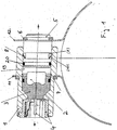
- FIG. 1 shows the pyromechanical separating element according to the invention installed in a pipe clamp that should be loosened if necessary.
- the pyromechanical separating element essentially consists of the housing 1 into which the pyrotechnic pressure element 2 is inserted via an insulating body 3 is, the electrical connector system 4, the locking bolt 5, the locking rings 6, 7 and the locking and force limiting element 8.
- This Locking and force limiting element 8 can be designed differently become.
- this locking and force limiting element 8 designed as a disc spring with crown-shaped incisions. This element sits in the locked state in the locking pin groove 9 and in the housing groove 10. An attempt is made to lock the locking pin 5 and the housing 1 pull apart, locks the locking and force limiting element 8. Only when overcoming a force caused by the spring tension of this element and by the geometric shape of the locking and force limiting element 8 and the grooves 9, 10 is set, the locking bolt 5 are pulled out of the housing 1.
- the two clamp ends 11, 12 with the pyromechanical separating element are firmly connected, even at high normal mechanical Loads that want to pull the clamp together or apart. Only in the case of an intentional separation, e.g. B. by emergency situations or Overload situations, which is connected via the electrical connector system 4 pyrotechnic pressure element 2 is subjected to an electric current surge, the pyrotechnic pressure element 2 is ignited and in the drive volume 19 generates high drive pressure through the combustion of the pyrotechnic substance, which in turn presses on the locking pin 5.
- the locking and force limiting element 8 becomes such deformed that the edges of the housing groove 10 and the locking bolt groove 9 die Shear off the spring washer elements.
- the locking and force limiting element 8 is designed as a sheet metal ring. This element will help you overcome the pull-out resistance also on the resulting from the drive pressure of the pyrotechnic pressure element 2 Extraction force achieved a direct punching of the sheet metal ring.
- Figure 3 shows a further embodiment of the locking and force limiting element 8 as a spring washer.
- the spring tension and groove shape determine both the level of the holding force and that of the pull-out resistance.
- the locking and force limiting element 8 snaps this into the groove 10 provided in the housing 1 and blocks it from being pulled out.
- the pyromechanical separating element can now be inserted into the clamp ends 11, 12, are used and pressed together with the locking rings 6, 7 are attached.
- FIG. 4 shows another embodiment of the separating element according to the invention shown.
- the locking bolt 5 is designed such that it when assembled presses against the shoulder of the housing groove 16 and then with one high pressing force is deformed. In principle, this process constitutes a kind of riveting
- the design of the groove 17 and the projection 18 and the type of Material design allow different locking forces to be set.
- the Cantilever 18 in this case represents the locking and force limiting element 8 represents.
Landscapes
- Engineering & Computer Science (AREA)
- General Engineering & Computer Science (AREA)
- Physics & Mathematics (AREA)
- Fluid Mechanics (AREA)
- Mechanical Engineering (AREA)
- Chemical & Material Sciences (AREA)
- Analytical Chemistry (AREA)
- Air Bags (AREA)
- Separation Using Semi-Permeable Membranes (AREA)
- Preparing Plates And Mask In Photomechanical Process (AREA)
- Treatment Of Liquids With Adsorbents In General (AREA)
- Automotive Seat Belt Assembly (AREA)
Abstract
Description
- Fig. 1
- eine Ausführungsform eines pyromechanischen Trennelements mit einer Tellerfeder mit kronenförmigen Einschnitten als Arretierungs- und Kraftbegrenzungselement,
- Fig. 2
- eine Ausführungsform analog Fig. 1, jedoch mit einem Blechring als Arretierungs- und Kraftbegrenzungselement,
- Fig. 3
- eine Ausführungsform analog Figur 1, jedoch mit einem Federring als Arretierungs- und Kraftbegrenzungselement und
- Fig. 4
- eine Ausführungsform analog Figur 1, jedoch mit einer radialen Auskragung am Verrastungsbolzen als Arretierungs- und Kraftbegrenzungselement.
Claims (5)
- Pyromechanisches Trennelement mit einem in einem Gehäuse (1) eingebauten hermetisch dichten pyrotechnischen Druckelement (2) mit einer gasentwickelnden pyrotechnischen Ladung und einem von diesem durch ein Antriebsvolumen (19) abgetrennten lösbaren und in das Gehäuse (1) eingeschobenen Verrastungsbolzen (5), wobei am Gehäuse (1) ein erster Befestigungspunkt und am Verrastungsbolzen (5) ein zweiter Befestigungspunkt angeordnet sind und der Verrastungsbolzen (5) über ein Arretierungs- und Kraftbegrenzungselement (8) am Gehäuse (1) verankert ist.
- Trennelement nach Anspruch 1, dadurch gekennzeichnet, dass das Arretierungs- und Kraftbegrenzungselement (8) eine Tellerfeder mit bevorzugt kronenförmigen Einschnitten ist, welche im verrasteten Zustand sowohl in einer Verrastungsbolzennut (9) im Verrastungsbolzen (5) als auch in einer Gehäusenut (10) sitzt.
- Trennelement nach Anspruch 1, dadurch gekennzeichnet, dass das Arretierungs- und Kraftbegrenzungselement (8) ein Blechring oder ein Federring ist, der im verrasteten Zustand sowohl in einer Verrastungsbolzennut (9) im Verrastungsbolzen (5) als auch in einer Gehäusenut (10) sitzt.
- Trennelement nach Anspruch 1, dadurch gekennzeichnet, dass das Arretierungs- und Kraftbegrenzungselement (8) eine radiale Auskragung (18) am Verrastungsbolzen (5) ist, die in eine Gehäusenut (16) am Gehäuse (1) eingreift.
- Trennelement nach einem der Ansprüche 1 bis 4, dadurch gekennzeichnet, dass auf dem Außenumfang des Verrastungsbolzens (5) ein in einer Nut eingelassener Dichtungsring (29) angeordnet ist.
Applications Claiming Priority (2)
| Application Number | Priority Date | Filing Date | Title |
|---|---|---|---|
| DE10303377A DE10303377A1 (de) | 2003-01-29 | 2003-01-29 | Pyromechanisches Trennelement |
| DE10303377 | 2003-01-29 |
Publications (2)
| Publication Number | Publication Date |
|---|---|
| EP1443296A1 true EP1443296A1 (de) | 2004-08-04 |
| EP1443296B1 EP1443296B1 (de) | 2007-08-08 |
Family
ID=32603013
Family Applications (1)
| Application Number | Title | Priority Date | Filing Date |
|---|---|---|---|
| EP04001764A Expired - Lifetime EP1443296B1 (de) | 2003-01-29 | 2004-01-28 | Pyromechanisches Trennelement |
Country Status (4)
| Country | Link |
|---|---|
| US (1) | US7188558B2 (de) |
| EP (1) | EP1443296B1 (de) |
| AT (1) | ATE369538T1 (de) |
| DE (2) | DE10303377A1 (de) |
Cited By (3)
| Publication number | Priority date | Publication date | Assignee | Title |
|---|---|---|---|---|
| EP1547873A3 (de) * | 2003-11-18 | 2005-08-17 | ISE Innomotive Systems Europe GmbH | Überrollschutzsystem für Kraftfahrzeuge mit einem ausfahrbaren Überrollkörper |
| DE102005001115A1 (de) * | 2005-01-08 | 2006-07-20 | Ise Innomotive Systems Europe Gmbh | Pyrotechnischer Aktuator |
| US9616846B2 (en) | 2014-04-22 | 2017-04-11 | Takata AG | Belt retractor |
Families Citing this family (14)
| Publication number | Priority date | Publication date | Assignee | Title |
|---|---|---|---|---|
| DE102005017868A1 (de) | 2005-04-19 | 2006-10-26 | Hirschmann Automotive Gmbh | Pyrotechnische Einheit für ein Sicherheitssystem, insbesondere eines Airbags oder eines Gurtstraffers eines Fahrzeugs |
| DE102005058721A1 (de) * | 2005-12-08 | 2007-06-14 | Trw Airbag Systems Gmbh | Pyrotechnische Aktuatoreinheit sowie Gassackmodul mit einer solchen Akruatoreinheit |
| WO2008054848A2 (en) * | 2006-03-30 | 2008-05-08 | Raytheon Company | Methods and apparatus for integrated locked thruster mechanism |
| US7762189B2 (en) * | 2006-12-29 | 2010-07-27 | Pacific Scientific Energetic Materials Company | Networked pyrotechnic actuator incorporating high-pressure bellows |
| US7775147B2 (en) * | 2008-03-17 | 2010-08-17 | Raytheon Company | Dual redundant electro explosive device latch mechanism |
| US8082848B2 (en) * | 2008-10-22 | 2011-12-27 | Raytheon Company | Missile with system for separating subvehicles |
| US8607705B2 (en) * | 2010-12-06 | 2013-12-17 | Systima Technologies Inc. | Low shock rocket body separation |
| DE102011013255B4 (de) | 2011-03-07 | 2024-01-04 | Zf Airbag Germany Gmbh | Entriegelungsvorrichtung |
| DE102012023877A1 (de) | 2012-12-06 | 2014-06-12 | Trw Airbag Systems Gmbh | Pyrotechnische aktuatorbaugruppe sowie gassackmodul mit einer solchen aktuatorbaugruppe |
| DE102013002363B4 (de) * | 2013-02-09 | 2017-03-23 | Autoliv Development Ab | Gassackeinheit und Halteteil zur Verwendung in einer solchen Gassackeinheit |
| RU2534856C1 (ru) * | 2013-04-23 | 2014-12-10 | Федеральное государственное унитарное предприятие "Федеральный центр двойных технологий "Союз" (ФГУП "ФЦДТ "Союз") | Пирозамок с расположением стяжного болта под углом к оси |
| EP2995822B1 (de) * | 2014-09-09 | 2019-11-13 | Arianegroup Sas | Pyrotechnischer Aktuator |
| DE102015004000A1 (de) * | 2015-03-30 | 2016-10-06 | Trw Airbag Systems Gmbh | Pyrotechnische Aktuatoreinheit, Gassackmodul mit einer solchen Aktuatoreinheit sowie Verfahren zur Herstellung einer pyrotechnischen Aktuatoreinheit |
| GB2601376A (en) * | 2020-11-30 | 2022-06-01 | Airbus Operations Ltd | Structural fuse |
Citations (6)
| Publication number | Priority date | Publication date | Assignee | Title |
|---|---|---|---|---|
| US4091621A (en) * | 1975-06-02 | 1978-05-30 | Networks Electronic Corp. | Pyrotechnic piston actuator |
| US4860698A (en) * | 1988-05-11 | 1989-08-29 | Networks Electronic Corp. | Pyrotechnic piston device |
| DE4326737C1 (de) * | 1993-08-09 | 1994-03-31 | Deutsche Aerospace | Elektrischer Auslöser |
| DE19922674A1 (de) * | 1999-05-18 | 2000-11-23 | Goetz Coenen | Pyrotechnischer Aktuator |
| EP1162333A1 (de) * | 2000-06-09 | 2001-12-12 | Giat Industries | Pyrotechnisches Schloss mit axialer Halterung seines Shaftes |
| DE10203710C1 (de) * | 2002-01-31 | 2003-02-13 | Thomas Magnete Gmbh | Pyrotechnischer Aktor |
Family Cites Families (51)
| Publication number | Priority date | Publication date | Assignee | Title |
|---|---|---|---|---|
| US2489984A (en) * | 1945-02-20 | 1949-11-29 | United Aircraft Corp | Explosive-release mechanism |
| US2585870A (en) * | 1945-03-26 | 1952-02-12 | Curtiss Wright Corp | Release mechanism |
| US2809584A (en) * | 1953-04-01 | 1957-10-15 | Smith Bernard | Connector ring for two stage rockets |
| US2815008A (en) * | 1956-06-15 | 1957-12-03 | Talco Engineering Company Inc | Ejection seat thruster |
| US2897799A (en) * | 1957-07-29 | 1959-08-04 | Ordnance Specialties Inc | Explosive cutter for parachute lines |
| US2959129A (en) * | 1959-02-18 | 1960-11-08 | Alfred P Warren | Missile-stage connecting and releasing device |
| US3072168A (en) * | 1959-11-25 | 1963-01-08 | Illinois Tool Works | Lock washer |
| US3903803A (en) * | 1960-05-12 | 1975-09-09 | Us Navy | Missile separation means |
| US3119298A (en) * | 1960-08-04 | 1964-01-28 | Hi Shear Corp | Explosively separable fastener |
| US3084597A (en) * | 1961-01-11 | 1963-04-09 | Raymond H Beyer | Explosive quick-disconnect |
| US3111808A (en) * | 1962-08-20 | 1963-11-26 | Rocket Power Inc | Thruster |
| US3199288A (en) * | 1963-03-20 | 1965-08-10 | Joseph A Nahas | Explosively actuated piston driver |
| US3244104A (en) * | 1964-03-25 | 1966-04-05 | Jimmie R Mills | Missile separating device |
| US3234727A (en) * | 1964-11-04 | 1966-02-15 | Ncr Co | Explosive motors |
| US3546999A (en) * | 1968-06-21 | 1970-12-15 | Unidynamics Phoenix | Release mechanism |
| US3661084A (en) * | 1969-09-03 | 1972-05-09 | Us Navy | Band release |
| FR2213231B1 (de) * | 1972-11-06 | 1976-08-20 | Peugeot & Renault | |
| US3902400A (en) * | 1974-03-13 | 1975-09-02 | Us Army | Pyrotechnic band release device |
| US4002120A (en) * | 1975-07-31 | 1977-01-11 | The United States Of America As Represented By The Secretary Of The Navy | Missile stage coupler |
| US4158322A (en) * | 1977-08-22 | 1979-06-19 | The United States Of America As Represented By The Secretary Of The Navy | Pyrotechnic separation device |
| JPS5912910Y2 (ja) * | 1978-08-25 | 1984-04-18 | 株式会社日本自動車部品総合研究所 | シ−トベルト引締め装置の逆戻り防止装置 |
| US4244386A (en) * | 1979-01-30 | 1981-01-13 | The United States Of America As Represented By The Secretary Of The Navy | Valve having pyrotechnic separation device |
| US4412420A (en) * | 1980-07-03 | 1983-11-01 | Networks Electronics Corp. | Explosive actuated pin puller |
| US4612857A (en) * | 1984-07-16 | 1986-09-23 | Mcdonnell Douglas Corporation | Ballistic gas fired device |
| US4608926A (en) * | 1984-09-13 | 1986-09-02 | Thiokol Corporation | Swivel type through bulkhead initiator |
| US4685376A (en) * | 1985-06-24 | 1987-08-11 | Mcdonnell Douglas Corporation | Separation system |
| US4671715A (en) * | 1986-04-03 | 1987-06-09 | Hi-Shear Corporation | Lesser shock separation fastener |
| FR2665951B1 (fr) * | 1990-08-20 | 1992-11-13 | Aerospatiale | Systeme de liaison cassable permettant de separer des pieces au moyen d'une charge detonante. |
| US5370343A (en) * | 1993-03-04 | 1994-12-06 | General Dynamics Corporation Space Systems Division | Arrangement for attachment and quick disconnect and jettison of rocket booster from space vehicle |
| US5566909A (en) * | 1993-09-08 | 1996-10-22 | Hughes Aircraft Company | System and method for deploying multiple probes |
| DE4332206C2 (de) * | 1993-09-22 | 1997-08-14 | Hs Tech & Design | Antriebsvorrichtung |
| US5579636A (en) * | 1995-03-21 | 1996-12-03 | Aerotech, Inc. | Pyrotechnic valve, igniter and combustion preheater for hybrid rocket motors |
| DE19532746A1 (de) * | 1995-09-05 | 1997-03-06 | Rheinmetall Ind Ag | Trennschraube |
| US5613706A (en) * | 1995-12-13 | 1997-03-25 | Morton International, Inc. | Self-contained inflator pyrotechnic initiator |
| US5695306A (en) * | 1996-05-08 | 1997-12-09 | Lockheed Martin Corp. | Fusible member connection apparatus and method |
| DE19728658A1 (de) * | 1997-07-04 | 1999-01-07 | Dynamit Nobel Ag | Pyrotechnisches Wirkelement |
| ES2131476B1 (es) * | 1997-09-26 | 2000-03-01 | Const Aeronauticas Sa | Sistema de fijacion y separacion de satelites. |
| DE19754793A1 (de) * | 1997-12-10 | 1999-06-17 | Dynamit Nobel Ag | Verbundanker mit einem pyrotechnischen Heiz- und Austreibgenerator |
| US6269748B1 (en) * | 1998-06-18 | 2001-08-07 | Nea Electronics, Inc. | Release mechanism |
| FR2787149B1 (fr) * | 1998-12-09 | 2001-01-05 | Giat Ind Sa | Dispositif de deverrouillage pyrotechnique |
| SE9900354L (sv) * | 1999-02-03 | 1999-11-22 | Saab Ericsson Space Ab | Förband vid rymdfarkost |
| FR2809461B1 (fr) * | 2000-05-29 | 2002-11-29 | Aerospatiale Matra Lanceurs St | Actionneur pyrotechnique a membrane deformable |
| US6568184B2 (en) * | 2000-08-04 | 2003-05-27 | Automotive Systems Laboratory, Inc. | Pyrotechnic actuator |
| US6403873B1 (en) * | 2000-08-22 | 2002-06-11 | The United States Of America As Represented By The Secretary Of The Navy | Torpedo joint band with in-water separation capability utilizing frangible link EEDs |
| DE10127483B4 (de) * | 2001-06-07 | 2014-02-13 | Magna Electronics Europe Gmbh & Co.Kg | Trennschraube und ihre Verwendung |
| CA2355504A1 (en) * | 2001-08-17 | 2003-02-17 | Yves Daunas | Autonomous gas powered ram |
| WO2003072394A2 (en) * | 2002-02-22 | 2003-09-04 | Automotive Systems Laboratory, Inc. | Airbelt inflator |
| FR2838818B1 (fr) * | 2002-04-19 | 2006-12-08 | Eads Launch Vehicules | Dispositif de liaison provisoire et de separation pyrotechnique de deux elements, sans rupture |
| US20040007123A1 (en) * | 2002-07-10 | 2004-01-15 | Ritchie Robert S. | Hermetically sealed actuator |
| US6925939B2 (en) * | 2003-04-29 | 2005-08-09 | Mark Allen Cleveland | Low shock separation bolt |
| US7001127B2 (en) * | 2003-10-20 | 2006-02-21 | Hi-Shear Technology | Non-pyrolytically actuated reduced-shock separation fastener |
-
2003
- 2003-01-29 DE DE10303377A patent/DE10303377A1/de not_active Withdrawn
-
2004
- 2004-01-28 EP EP04001764A patent/EP1443296B1/de not_active Expired - Lifetime
- 2004-01-28 DE DE502004004540T patent/DE502004004540D1/de not_active Expired - Lifetime
- 2004-01-28 AT AT04001764T patent/ATE369538T1/de not_active IP Right Cessation
- 2004-01-30 US US10/767,173 patent/US7188558B2/en not_active Expired - Lifetime
Patent Citations (6)
| Publication number | Priority date | Publication date | Assignee | Title |
|---|---|---|---|---|
| US4091621A (en) * | 1975-06-02 | 1978-05-30 | Networks Electronic Corp. | Pyrotechnic piston actuator |
| US4860698A (en) * | 1988-05-11 | 1989-08-29 | Networks Electronic Corp. | Pyrotechnic piston device |
| DE4326737C1 (de) * | 1993-08-09 | 1994-03-31 | Deutsche Aerospace | Elektrischer Auslöser |
| DE19922674A1 (de) * | 1999-05-18 | 2000-11-23 | Goetz Coenen | Pyrotechnischer Aktuator |
| EP1162333A1 (de) * | 2000-06-09 | 2001-12-12 | Giat Industries | Pyrotechnisches Schloss mit axialer Halterung seines Shaftes |
| DE10203710C1 (de) * | 2002-01-31 | 2003-02-13 | Thomas Magnete Gmbh | Pyrotechnischer Aktor |
Cited By (4)
| Publication number | Priority date | Publication date | Assignee | Title |
|---|---|---|---|---|
| EP1547873A3 (de) * | 2003-11-18 | 2005-08-17 | ISE Innomotive Systems Europe GmbH | Überrollschutzsystem für Kraftfahrzeuge mit einem ausfahrbaren Überrollkörper |
| DE102005001115A1 (de) * | 2005-01-08 | 2006-07-20 | Ise Innomotive Systems Europe Gmbh | Pyrotechnischer Aktuator |
| DE102005001115B4 (de) * | 2005-01-08 | 2009-03-12 | Automotive Group Ise Innomotive Systems Europe Gmbh | Pyrotechnischer Aktuator |
| US9616846B2 (en) | 2014-04-22 | 2017-04-11 | Takata AG | Belt retractor |
Also Published As
| Publication number | Publication date |
|---|---|
| US20040255811A1 (en) | 2004-12-23 |
| EP1443296B1 (de) | 2007-08-08 |
| ATE369538T1 (de) | 2007-08-15 |
| DE502004004540D1 (de) | 2007-09-20 |
| DE10303377A1 (de) | 2004-08-05 |
| US7188558B2 (en) | 2007-03-13 |
Similar Documents
| Publication | Publication Date | Title |
|---|---|---|
| EP1443296B1 (de) | Pyromechanisches Trennelement | |
| EP1074033B1 (de) | Vorrichtung zum auftrennen eines elektrischen stromkreises, insbesondere für hohe stromstärken | |
| EP1447640B1 (de) | Pyromechanisches Trennelement | |
| EP1179142B1 (de) | Pyrotechnischer aktuator | |
| DE2832879A1 (de) | Treibladungsanzuender | |
| DE69908971T2 (de) | Pyrotechnisch entriegelbare mechanische verbindungsvorrichtung | |
| DE102010011150A1 (de) | Sicherung für Kraftfahrzeugenergieleitung | |
| DE102011014869A1 (de) | Befestigungsvorrichtung zur lösbaren Befestigung eines Elements an einem fahrzeugfesten Bauteil | |
| EP1464544B1 (de) | Gehäuse mit Stromleiterschiene für eine Trennvorrichtung | |
| EP0882317A1 (de) | Batterie-kabelklemme für fahrzeuge | |
| DE112018005130T5 (de) | Elektrische schutzschaltvorrichtung | |
| DE19749133A1 (de) | Notabschalter für elektrische Stromkreise | |
| EP1535810A2 (de) | Gasgenerator | |
| DE102011113955A1 (de) | Elektrischer Schalter | |
| CH641555A5 (de) | Geschoss mit einem elektrischen zuender. | |
| DE19749135A1 (de) | Notabschalter für elektrische Stromkreise | |
| DE3421572C2 (de) | Sicherungseinrichtung für Zünder von Kleinraketengefechtsköpfen | |
| DE1955703C3 (de) | Elektrisch zu zündendes Schaltelement | |
| DE202019004348U1 (de) | Schnelltrennschalter | |
| DE69930233T2 (de) | Elektrischer Schaltschütz | |
| DE102011106517B4 (de) | Gasgenerator und Fahrzeugsicherheitssystem | |
| DE102010015240A1 (de) | Stromunterbrecher für Kraftfahrzeugenergieleiter | |
| DE102013100825B3 (de) | Pyro-mechanischer Aktuator und Verbindungsvorrichtung mit einem solchen Aktuator | |
| DE102010015239A1 (de) | Stromunterbrecher für eine Energieleitung | |
| DE299620C (de) |
Legal Events
| Date | Code | Title | Description |
|---|---|---|---|
| PUAI | Public reference made under article 153(3) epc to a published international application that has entered the european phase |
Free format text: ORIGINAL CODE: 0009012 |
|
| AK | Designated contracting states |
Kind code of ref document: A1 Designated state(s): AT BE BG CH CY CZ DE DK EE ES FI FR GB GR HU IE IT LI LU MC NL PT RO SE SI SK TR |
|
| AX | Request for extension of the european patent |
Extension state: AL LT LV MK |
|
| RIN1 | Information on inventor provided before grant (corrected) |
Inventor name: BREDE, UWE Inventor name: LAUCHT, HORST, DR. |
|
| RAP1 | Party data changed (applicant data changed or rights of an application transferred) |
Owner name: TRW AIRBAG SYSTEMS GMBH Owner name: DYNAMIT NOBEL AIS GMBHAUTOMOTIVE IGNITION SYSTEMS |
|
| REG | Reference to a national code |
Ref country code: DE Ref legal event code: 8566 |
|
| RAP1 | Party data changed (applicant data changed or rights of an application transferred) |
Owner name: DELPHI TECHNOLOGIES, INC. Owner name: TRW AIRBAG SYSTEMS GMBH |
|
| 17P | Request for examination filed |
Effective date: 20050204 |
|
| AKX | Designation fees paid |
Designated state(s): AT BE BG CH CY CZ DE DK EE ES FI FR GB GR HU IE IT LI LU MC NL PT RO SE SI SK TR |
|
| 17Q | First examination report despatched |
Effective date: 20060929 |
|
| GRAP | Despatch of communication of intention to grant a patent |
Free format text: ORIGINAL CODE: EPIDOSNIGR1 |
|
| GRAS | Grant fee paid |
Free format text: ORIGINAL CODE: EPIDOSNIGR3 |
|
| GRAA | (expected) grant |
Free format text: ORIGINAL CODE: 0009210 |
|
| AK | Designated contracting states |
Kind code of ref document: B1 Designated state(s): AT BE BG CH CY CZ DE DK EE ES FI FR GB GR HU IE IT LI LU MC NL PT RO SE SI SK TR |
|
| REG | Reference to a national code |
Ref country code: GB Ref legal event code: FG4D Free format text: NOT ENGLISH |
|
| REG | Reference to a national code |
Ref country code: CH Ref legal event code: EP |
|
| REG | Reference to a national code |
Ref country code: IE Ref legal event code: FG4D Free format text: LANGUAGE OF EP DOCUMENT: GERMAN |
|
| REF | Corresponds to: |
Ref document number: 502004004540 Country of ref document: DE Date of ref document: 20070920 Kind code of ref document: P |
|
| ET | Fr: translation filed | ||
| PG25 | Lapsed in a contracting state [announced via postgrant information from national office to epo] |
Ref country code: BG Free format text: LAPSE BECAUSE OF FAILURE TO SUBMIT A TRANSLATION OF THE DESCRIPTION OR TO PAY THE FEE WITHIN THE PRESCRIBED TIME-LIMIT Effective date: 20071108 Ref country code: FI Free format text: LAPSE BECAUSE OF FAILURE TO SUBMIT A TRANSLATION OF THE DESCRIPTION OR TO PAY THE FEE WITHIN THE PRESCRIBED TIME-LIMIT Effective date: 20070808 Ref country code: ES Free format text: LAPSE BECAUSE OF FAILURE TO SUBMIT A TRANSLATION OF THE DESCRIPTION OR TO PAY THE FEE WITHIN THE PRESCRIBED TIME-LIMIT Effective date: 20071119 Ref country code: NL Free format text: LAPSE BECAUSE OF FAILURE TO SUBMIT A TRANSLATION OF THE DESCRIPTION OR TO PAY THE FEE WITHIN THE PRESCRIBED TIME-LIMIT Effective date: 20070808 |
|
| NLV1 | Nl: lapsed or annulled due to failure to fulfill the requirements of art. 29p and 29m of the patents act | ||
| GBV | Gb: ep patent (uk) treated as always having been void in accordance with gb section 77(7)/1977 [no translation filed] |
Effective date: 20070808 |
|
| REG | Reference to a national code |
Ref country code: IE Ref legal event code: FD4D |
|
| PG25 | Lapsed in a contracting state [announced via postgrant information from national office to epo] |
Ref country code: GR Free format text: LAPSE BECAUSE OF FAILURE TO SUBMIT A TRANSLATION OF THE DESCRIPTION OR TO PAY THE FEE WITHIN THE PRESCRIBED TIME-LIMIT Effective date: 20071109 Ref country code: DK Free format text: LAPSE BECAUSE OF FAILURE TO SUBMIT A TRANSLATION OF THE DESCRIPTION OR TO PAY THE FEE WITHIN THE PRESCRIBED TIME-LIMIT Effective date: 20070808 |
|
| PG25 | Lapsed in a contracting state [announced via postgrant information from national office to epo] |
Ref country code: SK Free format text: LAPSE BECAUSE OF FAILURE TO SUBMIT A TRANSLATION OF THE DESCRIPTION OR TO PAY THE FEE WITHIN THE PRESCRIBED TIME-LIMIT Effective date: 20070808 Ref country code: GB Free format text: LAPSE BECAUSE OF FAILURE TO SUBMIT A TRANSLATION OF THE DESCRIPTION OR TO PAY THE FEE WITHIN THE PRESCRIBED TIME-LIMIT Effective date: 20070808 Ref country code: IE Free format text: LAPSE BECAUSE OF FAILURE TO SUBMIT A TRANSLATION OF THE DESCRIPTION OR TO PAY THE FEE WITHIN THE PRESCRIBED TIME-LIMIT Effective date: 20070808 Ref country code: PT Free format text: LAPSE BECAUSE OF FAILURE TO SUBMIT A TRANSLATION OF THE DESCRIPTION OR TO PAY THE FEE WITHIN THE PRESCRIBED TIME-LIMIT Effective date: 20080108 Ref country code: CZ Free format text: LAPSE BECAUSE OF FAILURE TO SUBMIT A TRANSLATION OF THE DESCRIPTION OR TO PAY THE FEE WITHIN THE PRESCRIBED TIME-LIMIT Effective date: 20070808 |
|
| PLBE | No opposition filed within time limit |
Free format text: ORIGINAL CODE: 0009261 |
|
| STAA | Information on the status of an ep patent application or granted ep patent |
Free format text: STATUS: NO OPPOSITION FILED WITHIN TIME LIMIT |
|
| PG25 | Lapsed in a contracting state [announced via postgrant information from national office to epo] |
Ref country code: SE Free format text: LAPSE BECAUSE OF FAILURE TO SUBMIT A TRANSLATION OF THE DESCRIPTION OR TO PAY THE FEE WITHIN THE PRESCRIBED TIME-LIMIT Effective date: 20071108 Ref country code: RO Free format text: LAPSE BECAUSE OF FAILURE TO SUBMIT A TRANSLATION OF THE DESCRIPTION OR TO PAY THE FEE WITHIN THE PRESCRIBED TIME-LIMIT Effective date: 20070808 |
|
| 26N | No opposition filed |
Effective date: 20080509 |
|
| BERE | Be: lapsed |
Owner name: DELPHI TECHNOLOGIES, INC. Effective date: 20080131 Owner name: TRW AIRBAG SYSTEMS G.M.B.H. Effective date: 20080131 |
|
| PG25 | Lapsed in a contracting state [announced via postgrant information from national office to epo] |
Ref country code: MC Free format text: LAPSE BECAUSE OF NON-PAYMENT OF DUE FEES Effective date: 20080131 |
|
| REG | Reference to a national code |
Ref country code: CH Ref legal event code: PL |
|
| PG25 | Lapsed in a contracting state [announced via postgrant information from national office to epo] |
Ref country code: CH Free format text: LAPSE BECAUSE OF NON-PAYMENT OF DUE FEES Effective date: 20080131 Ref country code: LI Free format text: LAPSE BECAUSE OF NON-PAYMENT OF DUE FEES Effective date: 20080131 |
|
| PG25 | Lapsed in a contracting state [announced via postgrant information from national office to epo] |
Ref country code: EE Free format text: LAPSE BECAUSE OF FAILURE TO SUBMIT A TRANSLATION OF THE DESCRIPTION OR TO PAY THE FEE WITHIN THE PRESCRIBED TIME-LIMIT Effective date: 20070808 |
|
| PG25 | Lapsed in a contracting state [announced via postgrant information from national office to epo] |
Ref country code: BE Free format text: LAPSE BECAUSE OF NON-PAYMENT OF DUE FEES Effective date: 20080131 |
|
| PG25 | Lapsed in a contracting state [announced via postgrant information from national office to epo] |
Ref country code: AT Free format text: LAPSE BECAUSE OF NON-PAYMENT OF DUE FEES Effective date: 20080128 |
|
| PG25 | Lapsed in a contracting state [announced via postgrant information from national office to epo] |
Ref country code: SI Free format text: LAPSE BECAUSE OF FAILURE TO SUBMIT A TRANSLATION OF THE DESCRIPTION OR TO PAY THE FEE WITHIN THE PRESCRIBED TIME-LIMIT Effective date: 20070808 |
|
| PG25 | Lapsed in a contracting state [announced via postgrant information from national office to epo] |
Ref country code: CY Free format text: LAPSE BECAUSE OF FAILURE TO SUBMIT A TRANSLATION OF THE DESCRIPTION OR TO PAY THE FEE WITHIN THE PRESCRIBED TIME-LIMIT Effective date: 20070808 |
|
| PG25 | Lapsed in a contracting state [announced via postgrant information from national office to epo] |
Ref country code: LU Free format text: LAPSE BECAUSE OF NON-PAYMENT OF DUE FEES Effective date: 20080128 Ref country code: HU Free format text: LAPSE BECAUSE OF FAILURE TO SUBMIT A TRANSLATION OF THE DESCRIPTION OR TO PAY THE FEE WITHIN THE PRESCRIBED TIME-LIMIT Effective date: 20080209 |
|
| PG25 | Lapsed in a contracting state [announced via postgrant information from national office to epo] |
Ref country code: TR Free format text: LAPSE BECAUSE OF FAILURE TO SUBMIT A TRANSLATION OF THE DESCRIPTION OR TO PAY THE FEE WITHIN THE PRESCRIBED TIME-LIMIT Effective date: 20070808 |
|
| REG | Reference to a national code |
Ref country code: DE Ref legal event code: R082 Ref document number: 502004004540 Country of ref document: DE Representative=s name: BERNHARD MEHNERT, DE |
|
| REG | Reference to a national code |
Ref country code: DE Ref legal event code: R081 Ref document number: 502004004540 Country of ref document: DE Owner name: TRW AIRBAG SYSTEMS GMBH, DE Free format text: FORMER OWNER: DELPHI TECHNOLOGIES, INC., TRW AIRBAG SYSTEMS GMBH, , US Effective date: 20120125 Ref country code: DE Ref legal event code: R082 Ref document number: 502004004540 Country of ref document: DE Representative=s name: MEHNERT, BERNHARD, DE Effective date: 20120125 Ref country code: DE Ref legal event code: R081 Ref document number: 502004004540 Country of ref document: DE Owner name: TRW AIRBAG SYSTEMS GMBH, DE Free format text: FORMER OWNERS: DELPHI TECHNOLOGIES, INC., TROY, MICH., US; TRW AIRBAG SYSTEMS GMBH, 84544 ASCHAU, DE Effective date: 20120125 |
|
| REG | Reference to a national code |
Ref country code: FR Ref legal event code: TP Owner name: TRW AIRBAG SYSTEMS GMBH, DE Effective date: 20120302 |
|
| PGFP | Annual fee paid to national office [announced via postgrant information from national office to epo] |
Ref country code: IT Payment date: 20120117 Year of fee payment: 9 |
|
| PG25 | Lapsed in a contracting state [announced via postgrant information from national office to epo] |
Ref country code: IT Free format text: LAPSE BECAUSE OF NON-PAYMENT OF DUE FEES Effective date: 20130128 |
|
| REG | Reference to a national code |
Ref country code: FR Ref legal event code: PLFP Year of fee payment: 13 |
|
| REG | Reference to a national code |
Ref country code: FR Ref legal event code: PLFP Year of fee payment: 14 |
|
| REG | Reference to a national code |
Ref country code: FR Ref legal event code: PLFP Year of fee payment: 15 |
|
| REG | Reference to a national code |
Ref country code: DE Ref legal event code: R082 Ref document number: 502004004540 Country of ref document: DE Representative=s name: MEHNERT, BERNHARD, DE Ref country code: DE Ref legal event code: R081 Ref document number: 502004004540 Country of ref document: DE Owner name: ZF AIRBAG GERMANY GMBH, DE Free format text: FORMER OWNER: TRW AIRBAG SYSTEMS GMBH, 84544 ASCHAU, DE |
|
| PGFP | Annual fee paid to national office [announced via postgrant information from national office to epo] |
Ref country code: FR Payment date: 20221208 Year of fee payment: 20 |
|
| PGFP | Annual fee paid to national office [announced via postgrant information from national office to epo] |
Ref country code: DE Payment date: 20230131 Year of fee payment: 20 |
|
| P01 | Opt-out of the competence of the unified patent court (upc) registered |
Effective date: 20230628 |
|
| REG | Reference to a national code |
Ref country code: DE Ref legal event code: R071 Ref document number: 502004004540 Country of ref document: DE |