EP1443248A1 - Steuervorrichtung für geschwindigkeitswechselgetriebeeinheit, steuerverfahren und kraftfahrzeug - Google Patents
Steuervorrichtung für geschwindigkeitswechselgetriebeeinheit, steuerverfahren und kraftfahrzeug Download PDFInfo
- Publication number
- EP1443248A1 EP1443248A1 EP02775505A EP02775505A EP1443248A1 EP 1443248 A1 EP1443248 A1 EP 1443248A1 EP 02775505 A EP02775505 A EP 02775505A EP 02775505 A EP02775505 A EP 02775505A EP 1443248 A1 EP1443248 A1 EP 1443248A1
- Authority
- EP
- European Patent Office
- Prior art keywords
- gear
- clutch
- friction clutch
- driver
- type transmission
- Prior art date
- Legal status (The legal status is an assumption and is not a legal conclusion. Google has not performed a legal analysis and makes no representation as to the accuracy of the status listed.)
- Granted
Links
Images


Classifications
-
- F—MECHANICAL ENGINEERING; LIGHTING; HEATING; WEAPONS; BLASTING
- F16—ENGINEERING ELEMENTS AND UNITS; GENERAL MEASURES FOR PRODUCING AND MAINTAINING EFFECTIVE FUNCTIONING OF MACHINES OR INSTALLATIONS; THERMAL INSULATION IN GENERAL
- F16H—GEARING
- F16H63/00—Control outputs from the control unit to change-speed- or reversing-gearings for conveying rotary motion or to other devices than the final output mechanism
- F16H63/40—Control outputs from the control unit to change-speed- or reversing-gearings for conveying rotary motion or to other devices than the final output mechanism comprising signals other than signals for actuating the final output mechanisms
- F16H63/48—Signals to a parking brake or parking lock; Control of parking locks or brakes being part of the transmission
-
- B—PERFORMING OPERATIONS; TRANSPORTING
- B60—VEHICLES IN GENERAL
- B60T—VEHICLE BRAKE CONTROL SYSTEMS OR PARTS THEREOF; BRAKE CONTROL SYSTEMS OR PARTS THEREOF, IN GENERAL; ARRANGEMENT OF BRAKING ELEMENTS ON VEHICLES IN GENERAL; PORTABLE DEVICES FOR PREVENTING UNWANTED MOVEMENT OF VEHICLES; VEHICLE MODIFICATIONS TO FACILITATE COOLING OF BRAKES
- B60T1/00—Arrangements of braking elements, i.e. of those parts where braking effect occurs specially for vehicles
- B60T1/005—Arrangements of braking elements, i.e. of those parts where braking effect occurs specially for vehicles by locking of wheel or transmission rotation
-
- B—PERFORMING OPERATIONS; TRANSPORTING
- B60—VEHICLES IN GENERAL
- B60T—VEHICLE BRAKE CONTROL SYSTEMS OR PARTS THEREOF; BRAKE CONTROL SYSTEMS OR PARTS THEREOF, IN GENERAL; ARRANGEMENT OF BRAKING ELEMENTS ON VEHICLES IN GENERAL; PORTABLE DEVICES FOR PREVENTING UNWANTED MOVEMENT OF VEHICLES; VEHICLE MODIFICATIONS TO FACILITATE COOLING OF BRAKES
- B60T1/00—Arrangements of braking elements, i.e. of those parts where braking effect occurs specially for vehicles
- B60T1/02—Arrangements of braking elements, i.e. of those parts where braking effect occurs specially for vehicles acting by retarding wheels
- B60T1/06—Arrangements of braking elements, i.e. of those parts where braking effect occurs specially for vehicles acting by retarding wheels acting otherwise than on tread, e.g. employing rim, drum, disc, or transmission or on double wheels
- B60T1/062—Arrangements of braking elements, i.e. of those parts where braking effect occurs specially for vehicles acting by retarding wheels acting otherwise than on tread, e.g. employing rim, drum, disc, or transmission or on double wheels acting on transmission parts
-
- B—PERFORMING OPERATIONS; TRANSPORTING
- B60—VEHICLES IN GENERAL
- B60T—VEHICLE BRAKE CONTROL SYSTEMS OR PARTS THEREOF; BRAKE CONTROL SYSTEMS OR PARTS THEREOF, IN GENERAL; ARRANGEMENT OF BRAKING ELEMENTS ON VEHICLES IN GENERAL; PORTABLE DEVICES FOR PREVENTING UNWANTED MOVEMENT OF VEHICLES; VEHICLE MODIFICATIONS TO FACILITATE COOLING OF BRAKES
- B60T13/00—Transmitting braking action from initiating means to ultimate brake actuator with power assistance or drive; Brake systems incorporating such transmitting means, e.g. air-pressure brake systems
- B60T13/10—Transmitting braking action from initiating means to ultimate brake actuator with power assistance or drive; Brake systems incorporating such transmitting means, e.g. air-pressure brake systems with fluid assistance, drive, or release
- B60T13/66—Electrical control in fluid-pressure brake systems
- B60T13/662—Electrical control in fluid-pressure brake systems characterised by specified functions of the control system components
-
- F—MECHANICAL ENGINEERING; LIGHTING; HEATING; WEAPONS; BLASTING
- F16—ENGINEERING ELEMENTS AND UNITS; GENERAL MEASURES FOR PRODUCING AND MAINTAINING EFFECTIVE FUNCTIONING OF MACHINES OR INSTALLATIONS; THERMAL INSULATION IN GENERAL
- F16H—GEARING
- F16H61/00—Control functions within control units of change-speed- or reversing-gearings for conveying rotary motion ; Control of exclusively fluid gearing, friction gearing, gearings with endless flexible members or other particular types of gearing
- F16H61/0059—Braking of gear output shaft using simultaneous engagement of friction devices applied for different gear ratios
-
- F—MECHANICAL ENGINEERING; LIGHTING; HEATING; WEAPONS; BLASTING
- F16—ENGINEERING ELEMENTS AND UNITS; GENERAL MEASURES FOR PRODUCING AND MAINTAINING EFFECTIVE FUNCTIONING OF MACHINES OR INSTALLATIONS; THERMAL INSULATION IN GENERAL
- F16H—GEARING
- F16H3/00—Toothed gearings for conveying rotary motion with variable gear ratio or for reversing rotary motion
- F16H3/02—Toothed gearings for conveying rotary motion with variable gear ratio or for reversing rotary motion without gears having orbital motion
- F16H3/08—Toothed gearings for conveying rotary motion with variable gear ratio or for reversing rotary motion without gears having orbital motion exclusively or essentially with continuously meshing gears, that can be disengaged from their shafts
- F16H3/087—Toothed gearings for conveying rotary motion with variable gear ratio or for reversing rotary motion without gears having orbital motion exclusively or essentially with continuously meshing gears, that can be disengaged from their shafts characterised by the disposition of the gears
- F16H3/089—Toothed gearings for conveying rotary motion with variable gear ratio or for reversing rotary motion without gears having orbital motion exclusively or essentially with continuously meshing gears, that can be disengaged from their shafts characterised by the disposition of the gears all of the meshing gears being supported by a pair of parallel shafts, one being the input shaft and the other the output shaft, there being no countershaft involved
-
- F—MECHANICAL ENGINEERING; LIGHTING; HEATING; WEAPONS; BLASTING
- F16—ENGINEERING ELEMENTS AND UNITS; GENERAL MEASURES FOR PRODUCING AND MAINTAINING EFFECTIVE FUNCTIONING OF MACHINES OR INSTALLATIONS; THERMAL INSULATION IN GENERAL
- F16H—GEARING
- F16H3/00—Toothed gearings for conveying rotary motion with variable gear ratio or for reversing rotary motion
- F16H3/02—Toothed gearings for conveying rotary motion with variable gear ratio or for reversing rotary motion without gears having orbital motion
- F16H3/08—Toothed gearings for conveying rotary motion with variable gear ratio or for reversing rotary motion without gears having orbital motion exclusively or essentially with continuously meshing gears, that can be disengaged from their shafts
- F16H3/087—Toothed gearings for conveying rotary motion with variable gear ratio or for reversing rotary motion without gears having orbital motion exclusively or essentially with continuously meshing gears, that can be disengaged from their shafts characterised by the disposition of the gears
- F16H3/091—Toothed gearings for conveying rotary motion with variable gear ratio or for reversing rotary motion without gears having orbital motion exclusively or essentially with continuously meshing gears, that can be disengaged from their shafts characterised by the disposition of the gears including a single countershaft
- F16H3/0915—Toothed gearings for conveying rotary motion with variable gear ratio or for reversing rotary motion without gears having orbital motion exclusively or essentially with continuously meshing gears, that can be disengaged from their shafts characterised by the disposition of the gears including a single countershaft with coaxial input and output shafts
-
- F—MECHANICAL ENGINEERING; LIGHTING; HEATING; WEAPONS; BLASTING
- F16—ENGINEERING ELEMENTS AND UNITS; GENERAL MEASURES FOR PRODUCING AND MAINTAINING EFFECTIVE FUNCTIONING OF MACHINES OR INSTALLATIONS; THERMAL INSULATION IN GENERAL
- F16H—GEARING
- F16H61/00—Control functions within control units of change-speed- or reversing-gearings for conveying rotary motion ; Control of exclusively fluid gearing, friction gearing, gearings with endless flexible members or other particular types of gearing
- F16H61/68—Control functions within control units of change-speed- or reversing-gearings for conveying rotary motion ; Control of exclusively fluid gearing, friction gearing, gearings with endless flexible members or other particular types of gearing specially adapted for stepped gearings
- F16H61/684—Control functions within control units of change-speed- or reversing-gearings for conveying rotary motion ; Control of exclusively fluid gearing, friction gearing, gearings with endless flexible members or other particular types of gearing specially adapted for stepped gearings without interruption of drive
- F16H61/688—Control functions within control units of change-speed- or reversing-gearings for conveying rotary motion ; Control of exclusively fluid gearing, friction gearing, gearings with endless flexible members or other particular types of gearing specially adapted for stepped gearings without interruption of drive with two inputs, e.g. selection of one of two torque-flow paths by clutches
Definitions
- the present invention relates to a control device and a control method of the gear type transmission, and an automobile, and particularly to a device having the parking lock function to lock the vehicle especially when parking and a method thereof.
- the parking lock device for the conventional gear type transmission is disclosed in the Japanese Patent Application Laid-Open No. 9-295561.
- Lock mechanism which has a lock lever which engages with the parking gear when the engine is stopped and disengages with the parking lock when the engine is operated, an actuator which operates this lock lever, and a control means which operates this lock mechanism are provided in the device described in this patent gazette.
- the lock mechanism is operated when the engine is at an off state, and the rotation of the parking gear is prevented automatically. Therefore, even when the operation of a side brake to the position where the vehicle is parked is uncertain, the vehicle can be prevented from moving in contradiction to the intention.
- the configuration of the transmission is complicated, and its weight is also increased because the parking lock device to lock the vehicle when parking must be newly provided with some components separately in the gear type transmission as mentioned above.
- An object of the present invention is provide a control device and a control method of the gear type transmission which can lock the vehicle by using existing parts without providing the parking lock device with some components separately.
- the gear position where said mesh type clutch is engaged is changed over according to the inclination of the road where the vehicle is parked.
- FIG. 1 (a) is a block diagram showing the whole configuration of the control device of the gear type transmission.
- Transmission 6 comprises gear type speed change mechanism 5 which includes two or more gear trains, mesh type clutch 3 which switches the power transfer route of this gear trains, and second friction clutch 4 (referred as an assist clutch) which enables the torque transfer under shifting.
- Gear type speed change mechanism 5 comprises is an input shaft (103 in FIG. 2, for instance), counter shaft (120), an output shaft (104) and gear trains mounted on each shaft which are always engaged.
- Gear train (113, 114, 115, 116, 141, 142) of output shaft (104) is installed in idling respectively for output shaft (104).
- Said gear type speed change mechanism 5 receives the operation where the fixed gear of two or more gear trains (113, 114, 115, 116, 141, 142) is rotated in synchronization with output shaft (104) by mesh type clutch 3. As a result, the fixed transmission gear ratio will be set in gear type speed change mechanism 5. The change of the gear by mesh type clutch 3 will be explained later by using FIG. 4.
- the first friction clutch 2 is released in the conventional automatic manual transmission, and the power transfer from motor 1 is intercepted temporarily when the speed change.
- said mesh type clutch 3 is operated by shift/selection actuator 8 driven electrically or with the oil pressure, and said gear train is selected to become the fixed gear position.
- the first friction clutch 2 is engaged again, and the speed change is completed.
- the uncomfortable feeling is given to the driver by generating the torque interruption during shifting.
- the second friction clutch 4 is engaged by controlling the control amount for the clutch by assist actuator 7 driven electrically or with oil pressure with the first friction clutch 2 engaged in the transmission shown in FIG. 1.
- the fixed transmission gear ratio is set in gear type speed change mechanism 5 by engaging the second friction clutch 4 because the fixed gear wheel is engaged with the second friction clutch 4.
- Parking demand detecting means 9 detects the intention of the drive r who parks the vehicle. It is possible to detect the intention of the driver who starts said motor 1 from the state of the stop. As one example, there is a signal from the inhibitor switch output by working with the shift lever provided on the driver's seat side. This is described later by using FIG. 7 (a) and FIG. 7(b).
- Control device 10 is a microcomputer into which a basic program which carries out the speed change operation based on the input signal and the program which achieves the parking lock are built. Control device 10 inputs the rotating speed of each shaft which composes gear type speed change mechanism 5, rotating speed Ni of the input shaft, rotating speed No of the output shaft, rotating speed Ne of motor 1, throttle opening TVO which controls the torque output from motors 1, etc.
- control device 10 makes assist actuator 7 and shift/selection actuator 8 work to make the second friction clutch 4 and mesh type clutch 3 engaged at the same time.
- the wheel can be locked by causing the state that two different gear trains engage with each other at the same time in gear type speed change mechanism 5, in a word, double engaging.
- the parking lock of the vehicle can be achieved by using existing parts without adding new parts by adopting the configuration described above. Moreover, It is possible to make easily the transmission and to lighten it.
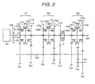
- FIG. 2 is a schematic view showing the configuration of the gear type speed change mechanism.
- This figure is a schematic view of the speed change mechanism of a so-called front engine rear drive method where the driving wheel is a rear wheel.
- Motor 101 first friction clutch 102, input shaft 103 of gear type speed change mechanism 5, which doubles as the output shaft of the first friction clutch 102, output shaft 104 provided on the same shaft as input shaft 103, counter shaft 120 provided in parallel with output shaft 104, driven gears 113, 114, 115, 116, 141 and 142 of the 1st gear, the 2nd gear, the 3rd gear, the 4th gear, the 5th gear, and reverse gear are provided rotatably on output shaft 104.
- Counter shaft 120 is arranged in parallel with output shaft 104.
- Drive gears 121, 122, 123, 124, 143 and 144 of the 1st gear, the 2nd gear, the 3rd gear, the 4th gear, the 5th gear, and the reverse gear are provided on counter shaft as one body, which engage with each gear 113, 114, 115, 116, 141 and 142.
- idle gears 145 and 146 are provided on idling shaft 147 arranged in parallel as one body. Idle gear 145 always engages with drive gear 144 at said reverse gear position.
- idl e gear 146 always engages with driven gear 142 at said reverse gear position.
- driven gears 113, 114 selectively engage with output shaft 104 with the 1st gear - the 2nd gear mesh type clutch 125 which comprises sleeve 125a, synchronizer ring 125b, gear spline 125c, and clutch hub 125d.
- driven gears 115, 116 selectively engage with output shaft 104 with the 3rd gear - the 4th gear mesh type clutch 117 which comprises sleeve 117a, synchronizer ring 117b, gear spline 117c, and clutch hub 117d.
- driven gears 141, 142 selectively engage with output shaft 104 with the 5th gear - reverse gear mesh type clutch 140 which comprises sleeve 140a, synchronizer ring 140b, gear spline 140c, and clutch hub 140d.
- the 1st gear - the 2nd gear mesh type clutch 125 is moved to the driven gear 113 side with the speed change operation mechanism, and engaged with output shaft 104.
- the rotation of input shaft 103 is decelerated most with gears 113, 121, and transmitted to output shaft 104.
- the 1st gear is obtained.
- the 1 st gear - the 2nd gear mesh type clutch 125 is engaged with driven gear 114 side, and the 2nd gear is obtained.
- the 3rd gear - the 4th gear mesh type clutch 117 is engaged with driven gear 115 or 116, and the 3rd gear or 4th gear is obtained.
- the 5th gear - the mesh type clutch 140 is engaged with driven gear 141 or 142, and the 5th gear or the reverse gear is obtained.
- the second friction clutch 4 is provided on output shaft 104.
- the multiplate wet clutch is used for the second friction clutch 4. Power is transmitted from the assist drive gear 119 provided on counter shaft 120 to output shaft 104 through assist dnven gear 118 provided on output shaft 104 as the control amount given to the clutch is increased.
- the gear ratio of said assist drive gear 119 and driven gear 118 is substantially set to the 3. 5th gear.
- the second friction clutch 4 is made to work and the gear shock is reduced in the 1st - 2nd speed change, the 2nd - 3rd speed change, the 3rd - 2nd speed change, and the 2nd - 1st speed change where the gear shock by said torque interruption is large.
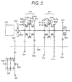
- FIG. 3 is a schematic view showing the configuration of the gear type speed change mechanism, the schematic view of the speed change mechani sm of a so-called FF method in which driving wheels become front wheels.
- Motor 101 and gear type speed change mechanism 5 are laid out sideways to the traveling direction of the vehicle in the engine room in case of the front engine front drive method. Therefore, the state of the 3rd gear is formed by installing the second friction clutch in the gear train of the 3rd gear to engage it completely because the installing space is restricted compared with the front engine rear drive method. As a result, omitting the synchronizer ring of the 3rd gear and the gear train corresponding to 3.5th gear becomes possible, and the configuration of the transmission is miniaturized.
- motor 501 there are provided motor 501, the first friction clutch 502, Input shaft 503 of gear type speed change mechanism 5 which doubles output shaft of the first friction clutch 502, drive gear 506, 507, 508, and 509 for the 1st gear, the 2nd gear, the 4th gear and the 5th gear provided on input shaft 503 rotatably, and output shaft 504 arranged in parallel with input shaft 503.
- gear type speed change mechanism 5 which doubles output shaft of the first friction clutch 502, drive gear 506, 507, 508, and 509 for the 1st gear, the 2nd gear, the 4th gear and the 5th gear provided on input shaft 503 rotatably, and output shaft 504 arranged in parallel with input shaft 503.
- one body driven gear 511, 512, 513, and 514 for the 1st gear, the 2nd gear, the 4th gear, and the 5th gear that always engage with said drive gear 506, 507, 508 and 509.
- Two adjoining drive gears 506, 507 are engaged with input shaft 503 selectively with the 1st gear - the 2nd gear mesh type clutch 516 of well-known configuration which comprises sleeve 516a, synchronizer ring 516b, gear spline 516c, and clutch hub 516d.
- drive gears 508, 509 is selectively engaged with input shaft 503 with the 4th gear - the 5th gear mesh type clutch 517 which comprises sleeve 517a, synchronizer ring 517b, gear spline 517c, and clutch hub 517d.
- the drive gear for the reverse gear position not shown in figure is selectively engaged with input shaft 503 with the reverse gear mesh type clutch.
- the 1 st gear - the 2nd gear mesh type clutch 516 is moved to drive gear 506 side with the speed change operation mechanism, and is engaged with input shaft 503.
- the rotation of input shaft 503 is decelerated most with gear 506, 511, and transmitted to output shaft 504 to obtain the 1st gear.
- the 1st gear - the 2nd gear mesh type clutch 516 is engaged with drive gear 507, and the 2nd gear is obtained.
- the 4th gear - the 5th gear mesh type clutch 517 is engaged with the side of drive gear 508 or 509, and the 4th gear or the 5th gear is obtained.
- the reverse gear mesh type clutch not shown in figure is engaged with the reverse gear position drive gear, and the reverse gear is obtained.
- Drive gear 510 is provided on input shaft 503 rotatably.
- the second friction clutch 505 is engaged with this drive gear 510.
- the control amount is increased, the power is transmitted to output shaft 504 through driven gear 515. Therefore, the torque interruption under shifting can be controlled as described in FIG. 2.
- the 3rd gear is obtained by completely engaging with the second friction clutch 505, and two functions of the torque assist and the 3rd gear steady state run can be achieved.
- Output shaft 504 has drive gear 520 which always engages with ring gear 521 of differential device 522. The power is transmitted to right and left axle shafts 523 through this differential device 522, and the front wheels of the vehicle are driven.
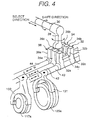
- FIG. 4 is a perspective view of the speed change operation mechanism used for the gear type transmission. Shift and select shaft 30 moved in an axial direction when selecting and turned when shifting is provided as shown in FIG. 4. Moreover, shift and select lever 38 selectively engaged with 1st gear and 2nd gear shift yoke 32, 3rd and 4th gear shift yoke 34, and 5th gear and reverse shift yoke 36 is provided on this shift and select shaft 30 as each gear shift yoke.
- the 1st gear and 2nd gear engaging ditch 32c for engaging shift and select lever 38 by 1st gear engaging flange 32a and 2nd gear engaging flange 32b are formed for 1st gear and 2nd gear shift yoke 32.
- the 3rd gear and 4th gear engaging ditch 34c for engaging shift and select lever 38 by 3rd gear engaging flange 34a and 2nd gear engaging flange 34b are formed for 3rd gear and 4th gear shift yoke 34.
- the 5th gear and reverse gear engaging ditch 36c for engaging shift and select lever 38 by 5th gear engaging flange 36a and reverse gear engaging flange 36b are formed for 5th gear and reverse gear shift yoke 36.
- 1st gear and 2nd gear shift yoke 32, 3rd and 4th gear shift yoke 34, and 5th gear and reverse gear shift yoke 36 are fixed on lowspeed side shift shaft 40, high-speed side shift shaft 42, and highest speed side shift shaft 44 supported in the gearbox casing.
- Low-speed side fork 131 engaged with sleeve 125a is set on low-speed side shift shaft 40.
- High-speed side fork 132 engaged with sleeve 117a is set on high-speed side shift shaft 42.
- highest gear fork (not shown) is also set on highest gear shift shaft 44.
- Shift and select shaft 30 are driven by actuator 19 for select which moves it in an axial direction and actuator 20 for shift which turns it as described in FIG. 6.
- the desired mesh type clutch can be engaged or released by moving the sleeve and the hub which is adjacent to the sleeve.
- FIG. 6 is a block diagram showing the configuration of shift/select actuator used for the gear type transmission according to the first embodiment of the present invention.
- Oil pressure source 15 comprises chiefly electric pump 11, reservoir tank 12, and accumulator 13. The oil pressure generated by electric pump 11 and stored in accumulator 13 forms base pressure.
- oil pressure sensor 14 is provided on the piping for the base pressure, and start-up/stop of electric pump 11 is controlled by said control means 10 by using a signal from said oil pressure sensor.
- Actuator 19 for select which moves shift and select shaft 30 in an axial direction is worked with solenoid 18 for select connected with said oil pressure source 30.
- An electromagnetic flow control valve is used for solenoid 18 for select. Said shift and select shaft 30 can be moved in an axial direction based on the PWM control by said microcomputer which inputs the detection value of a stroke sensor (not shown) engaged with actuator 19 for select.
- actuator 20 for shift which turns shift and select shaft 30 is worked by solenoids 16 and 17 for shift connected with said oil pressure source 30.
- a proportional electromagnetic type pressure control valve is used for said solenoid.
- Said shift and select shaft 30 can be moved in an axial direction based on the PWM control by said microcomputer which inputs the detection value of a stroke sensor (not shown) engaged with actuator 19 for select.
- the fixed gear position can be composed by selectively engaging the mesh type clutch.
- FIG. 6 (a) is a partial sectional view showing the configuration of the second friction clutch used for the gear type transmission.
- the multiplate wet clutch is used for the second friction clutch as shown in the figure.
- Solenoid 29 for assist generates the oil pressure based on a command signal from said control device 10.
- a proportional electromagnetic pressure control valve is used for said solenoid 29, and the oil pressure proportional to the electric current which flows to the coil can be generated.
- Clutch piston 25 resists spring 24 and moves due to the generation of the oil pressure.
- Drive side plate 23 (rotates in synchronization with an outside drum in the figure) comes in contact driven side plate 27 (rotates in synchronization with output shaft 104) and transfers the power.
- Driven side plate 27, member 28, and output shaft 104 rotates together.
- Said solenoid 29 corresponds to assist actuator 7 described in FIG. 1.
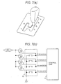
- FIG. 7(a) is an outline view of the select lever used as parking demand means 9. Moreover, FIG. 7(a)
- FIG. 7(b) is a schematic view of the inhibitor switch used as parking demand detecting means 9.
- P range as well as R range, N range and D range is provided in the select lever shown in FIG. 7 (a).
- the driver shifts the select lever to P range.
- the select lever is shifted to P range similarly.
- the signal of inhibitor switch 50 shown in FIG. 9 is generated.
- the output which corresponds to each range is input from inhibitor switch 50 shown in FIG. 7(b) to control device 10.
- the signal at a high level when the select lever is not selected and the signal at a low level when the select lever is selected is respectively input to control device 10.
- control device 10 executes the processing for locking the vehicle. It is possible to use the operation of the switch dedicated to the parking provided in the automobile interior or the touch panel of the monitor of the navigation system instead of said mechanical hardware as parking demand detecting means 9. That is, it is possible to provide the one like the parking switch in place of the configuration of FIG. 7.
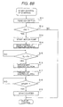
- FIG. 8(a) is a flow chart showing the control method by the control device of the gear type transmission. This flow chart shows the state when the motor is driving. Moreover, the content of processing shown in the flow chart of FIG. 8(a) is the program built into the microcomputer of control device 10 shown in FIG. 1.
- step S1 of FIG 8 (a) the signal of inhibitor switch 50 shown in FIG. 7(b) is read.
- step S2 the signal of said inhibitor switch 50 indicates the P range which shows the driver's parking demand in step S2. If the P range, the processing advances to step S3, otherwise, the parking lock control processing is ended.
- step S3 the signal of the speed sensor is read in step S3.
- step S5 it is judged whether the vehicle speed read is 0, in a word, whether the vehicle has stopped in step S4. If judged that the vehicle has stopped in step S4, the processing advances to step S5, otherwise, the parking lock control processing is ended.
- the command signal to solenoid 29 for assist shown in FIG. 6(a) is output so as to engage the second friction clutch 4.
- step S6 the state of double engaging is obtained by engaging both the second friction clutch and the mesh type clutch when driver's parking demand is detected, and the vehicle can surely be locked.
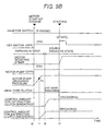
- FIG. 9(a) is a time chart when said parking lock control processing shown in FIG. 8(a) is executed.
- the select lever is operated by the driver and it is detected that the signal of the inhibitor switch indicates the P range at time to, the control amount to the second friction clutch is increased and the complete engaging state is obtained.
- the mesh type clutch forms the state of the 1 st gear.
- the double engaging state is obtained by engaging the second friction clutch and the vehicle is locked.
- the key switch is turned off by the driver and the motor is stopped, the charge with AC dynamo becomes impossible. Therefore, The discharge pressure of the electric pump decreases by turning off the power supply of said electric pump 11 at time t2 after the predetermined time ts passes.
- the control amount to the second friction clutch decreases due to the decrease in the oil pressure source and the clutch enters the releasing state.
- the first friction clutch generates the control amount to the clutch by the disc spring. The characteristic is in reverse characteristic from that of the second friction clutch because the clutch is released by releasing this control amount according to the oil pressure. Therefore, the first friction clutch enters the engaging state due to the decrease in the oil pressure source.
- said mesh type clutch engaged is made the forward gear in step S6 shown in FIG. 8(a) to park in gear, and the reverse gear is used besides the uphill.
- it is possible to detect the road inclination by using the value obtained by presuming the inclination based on the information used for the navigation system or the change of the vehicle speed, etc. as a method of detecting the road inc lination.
- the vehicle can surely be locked irrespective of the state of the drive or the stop of the motor by switching the gear of the mesh type clutch to be engaged according to the inclination of the road where the vehicle is parked.
- FIG. 8(b) is a flow chart showing the control method by the control device of the gear type transmission. This flow chart shows the case where the motor starts from the state of the stop. Moreover, the content of processing shown in the flow chart of FIG. 8 (b) is th e program built into the microcomputer of control device 10 shown in FIG. 1.
- step S11 of FIG. 8(b) the signal of the key switch provided on the driver's seat side is read.
- the signal of this key switch is a means which detects the start-up demand of motor 1 by said driver.
- step S12 it is judged whether the signal of said key switch is "ON” in step S12. If “ON”, the processing advances to step S13, otherwise, the control processing at start-up is ended.
- electric pump 11 shown in FIG. 5 is driven in step S13.
- signal PL of oil pressure sensor 14 is read in step S14. And, it is judged whether said oil pressure PL stored in accumulator 13 is larger than the predetermined value Po in step S15. If large, the processing advances to S16, otherwise, step S15 is repeated.
- step S16 the command signal to said solenoid 29 for assist of mentioning above is output to engage the second friction clutch 4 in step S16, and the control amount is increased.
- the counter shaft and the output shaft are set in the fixed transmission gear ratio through the assist driven gear and the assist drive gear.
- the state of double engaging is obtained by the processing of step S16 because the mesh type clutch is engaged with the fixed gear position beforehand when motor 1 is stopped according to the flow chart shown in FIG. 8(a).
- step S17 The first friction clutch 2 is released, and the torque transfer between the motor and the gear type transmission is intercepted in step S17. Next, it is judged whether the signal of said key switch is "START' in step S18. If "START', the processing advances to S18, otherwise, step S18 is repeated.
- a starter is started in step S19 at the end, and the motor begins to operate and the control at start-up is ended.
- the electric current to release the first friction clutch decreases by this temporary voltage drop, and there is a possibility that the clutch is engaged. Then, it is necessary to adjust the electric current which flows to the first friction clutch to the maximum value or to enlarge it more than the set values of the electric current at the usual releasing operation in said step S18 where the starter is working.
- FIG. 9(b) is a time chart when the control processing is executed at start-up shown in FIG. 8(b).
- the signal of the inhibitor switch (neutral switch) shows P range at time to.
- the key switch is operated by the driver and when it is detected that the signal of the key switch is turning on, electric pump 11 is turned on.
- the discharge pressure rises by driving electric pump 11, and the control amount to the second friction clutch is increased, and this clutch is brought into be the state of the complete engaging at time t1 which reaches the predetermined pressure Po.
- the control amount to the first friction clutch is raised at the same time the complete engaging of the second friction clutch is detected at time t2 and the first friction clutch is brought into be the state of releasing.
- FIG. 6(b) is a block diagram showing the outline of one embodiment of assist actuator.
- DC motor 51 shown in the figure is engaged with ball screw 54 by a gear wheel.
- the power in a rotation direction of said DC motor 51 is converted into the power in a lin e direction and amplified.
- the point of the ball screw is connected with piston 53 of master cylinder 52, and further resists the spring by rotating said DC motor 51 and moves.
- Said master cylinders 52 are connected to clutch piston 25 of the second friction clutch shown in FIG. 6(a) through the piping.
- the hydraulic operating fluid is filled in the piping, and said clutch piston 25 moves according to the movement of said piston 53, and the control amount to the second friction clutch 4 is generated. Connecting the clutch electric without using the oil pressure source shown in FIG.
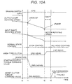
- FIG. 10(a) is a time chart showing the operation when the control method by the control device of the gear type transmission is executed, which shows the state where the vehicle stops from the state of running by driver's brake operation.
- the speed of the vehicle that is, the rotating speed of the output shaft of the transmission decreases when driver makes the brake ON at time t0.
- the clutch torque command value to the first friction clutch (start clutch torque command value) is assumed to be 0 when the output rotating speed falls below the predetermined rotating speed cNOSCOF, and the first friction clutch is released.
- start clutch torque command value is assumed to be 0 when the output rotating speed falls below the predetermined rotating speed cNOSCOF, and the first friction clutch is released.
- the rotating speed of the motor maintains idling speed
- the rotating speed of the input shaft of the transmission decreases according to the rotating speed of the output shaft.
- the mesh type clutch is changed from the 2nd gear to the 1st gear when the rotating speed of the output shaft decreases up to the fixed rotating speed cNOSTP at time t2, and the preliminary operation for the following start operation is done. And, it is judged that the driver demands the vehicle stop at time t3 which passes predetermined time cTMSTP from said time t2. And, clutch torque command value (assist clutch torque command value) to the second friction clutch is set in the fixed value TTHLHLD to make the second friction clutch half engaging.
- TTHLHLD to make the second friction clutch half engaging.
- said assist gear ratio Ga shows the ratio of the gear composed by the gear train in which the second friction clutch is installed.
- the circulation torque which corresponds to Ta ⁇ Td/G1 shown in said equation (1) is generated in the input shaft by generating assist clutch torque command value Ta.
- said circulation torque acts as a load to the torque which tries to rotate the input shaft from the tire side according to running resistance. Therefore, said equation is summarized as the following equation (2), and the assist clutch torque command value TTHLHLD required as a hill holding function is calculated by following equation (2).
- the hill holding function can be achieved by calculating the assist clutch torque command value required for the hill holding function, and assuming the second friction clutch to be the state of half engaging. As a result, it becomes possible to reduce driver's brake operation power required to maintain the vehicle position when the car is stopped, and the drivability can be improved.
- FIG. 10(b) is a time chart showing the operation when the control method by the control device of the gear type transmission is executed. This especially shows from the state of the hill holding described in FIG. 10 (a) to the state that the vehicle starts by said creep function.
- the speed change mechanisms such as automatic transmissions with hydraulic torque converter and continuously variable transmissions have a so-called creep function in which the vehicle gradually advances or backs, and generates the fixed drive shaft torque when the driver turns off the brake pedal from the state of the stop.
- creep function By using said creep function, it becomes possible to perform the start and the stop operation of the vehicle only by brake operation when the driver puts the car in the garage or crawls along in the traffic jam road.
- the function is acknowledged as an easy drive function by the user.
- a similar creep function can be achieved in the gear type transmission of the present invention.
- the creep function is achieved by doing the feedback control so that the first friction clutch may be made to be the state of the half engaging, and the rotating speed-of the motor may be maintained at a fixed rotating speed.
- the first friction clutch enters the state of the half engaging when the driver's brake operation is released from the state of the stop, and the creep operation is begun at time t0 shown in FIG. 10(b).
- the delay time will exist by the time the wheel begins rotating because there is a response delay until an actual clutch torque is generated even if the start clutch torque command value is set in step to assume the state of said half engaging. Therefore, as shown by the dotted line in FIG.
- the back and forth acceleration temporarily becomes negative by the running resistance during the delay of the response until the record clutch tor que is generated, and the retrogression of the vehicle is occurred in the start operation from the stop on the climbing-hill road.
- the phenomenon that the vehicle moves backward when changing from the stop of the vehicle to the creep condition on the climbing-hill road is generated.
- the second friction clutch is made to be the state of the half engaging with the car stopped as mentioned above in the present invention, and the clutch torque necessary to maintain the vehicle position is generated.
- the vehicle can promptly begin advancing because the torque by which the vehicle position is maintained at time t0 when brake operation was released is acted. Therefore, the vehicle is prevented from moving backward as mentioned above.
- the wheel can surely be locked even in an automatic manual transmission according to the present invention as explained above.
Applications Claiming Priority (3)
| Application Number | Priority Date | Filing Date | Title |
|---|---|---|---|
| JP2001342661 | 2001-11-08 | ||
| JP2001342661 | 2001-11-08 | ||
| PCT/JP2002/011596 WO2003040594A1 (fr) | 2001-11-08 | 2002-11-07 | Dispositif de commande d'unite de changement de vitesse de type engrenage, procede de commande et automobile |
Publications (3)
| Publication Number | Publication Date |
|---|---|
| EP1443248A1 true EP1443248A1 (de) | 2004-08-04 |
| EP1443248A4 EP1443248A4 (de) | 2005-02-02 |
| EP1443248B1 EP1443248B1 (de) | 2009-01-14 |
Family
ID=19156478
Family Applications (1)
| Application Number | Title | Priority Date | Filing Date |
|---|---|---|---|
| EP02775505A Expired - Fee Related EP1443248B1 (de) | 2001-11-08 | 2002-11-07 | Getriebe mit einer Steuereinheit |
Country Status (4)
| Country | Link |
|---|---|
| US (1) | US7201703B2 (de) |
| EP (1) | EP1443248B1 (de) |
| DE (1) | DE60230904D1 (de) |
| WO (1) | WO2003040594A1 (de) |
Cited By (1)
| Publication number | Priority date | Publication date | Assignee | Title |
|---|---|---|---|---|
| EP2159456A2 (de) | 2008-08-25 | 2010-03-03 | Getrag Ford Transmissions GmbH | Verfahren zum Steuern eines automatisierten Schaltgetriebes |
Families Citing this family (11)
| Publication number | Priority date | Publication date | Assignee | Title |
|---|---|---|---|---|
| JP4679889B2 (ja) * | 2004-11-26 | 2011-05-11 | 株式会社デンソー | 自動変速機制御装置 |
| GB2430989A (en) * | 2005-10-05 | 2007-04-11 | Bamford Excavators Ltd | Method of smoothly changing gear by using reverse clutch to retard input gearing |
| FR2892081B1 (fr) | 2005-10-18 | 2009-05-15 | Peugeot Citroen Automobiles Sa | Dispositif permettant de maintenir un vehicule automobile en place dans une pente, procede d'exploitation d'un tel dispositif et vehicule automobile equipe d'un tel dispositif |
| DE102005058776B4 (de) * | 2005-12-09 | 2018-03-01 | Zf Friedrichshafen Ag | Vorrichtung zum Steuern und/oder Regeln eines hydraulisch betätigbaren Schaltelementes einer Getriebeeinrichtung und Getriebeeinrichtung |
| JP2007225072A (ja) * | 2006-02-27 | 2007-09-06 | Hitachi Ltd | 自動車の制御装置 |
| DE102006024370A1 (de) * | 2006-05-24 | 2007-12-13 | Zf Friedrichshafen Ag | Mehrgruppengetriebe und Verfahren zum Gangwechsel bei einem Mehrgruppengetriebe |
| GB2445568B (en) * | 2006-10-03 | 2011-06-08 | Bamford Excavators Ltd | Method for controlling a vehicle transmission |
| DE102010003510B4 (de) * | 2010-03-31 | 2022-11-17 | Zf Friedrichshafen Ag | Verfahren zum Betreiben eines Antriebsstrangs |
| JP5716845B2 (ja) * | 2011-12-26 | 2015-05-13 | トヨタ自動車株式会社 | 油圧制御装置及び車両制御装置 |
| DE102017205662A1 (de) * | 2017-04-04 | 2018-10-04 | Zf Friedrichshafen Ag | Antriebsstrang für ein Fahrzeug |
| DE102019204076A1 (de) * | 2019-03-25 | 2020-10-01 | Vitesco Technologies Germany Gmbh | Verfahren zum Betrieb einer Antriebseinheit eines Fahrzeugs sowie Antriebseinheit |
Family Cites Families (19)
| Publication number | Priority date | Publication date | Assignee | Title |
|---|---|---|---|---|
| GB2174780B (en) * | 1985-04-11 | 1988-07-06 | Mitsubishi Motors Corp | Automatic transmission apparatus for vehicle |
| JPS61256054A (ja) * | 1985-05-08 | 1986-11-13 | Aisin Warner Ltd | 車輌用変速機の制御装置 |
| JP2728209B2 (ja) | 1988-08-04 | 1998-03-18 | キヤノン株式会社 | フレキシブル基板固定装置 |
| JPH0280258A (ja) | 1988-09-16 | 1990-03-20 | Sharp Corp | 画像形成素子 |
| JPH0529408Y2 (de) * | 1988-12-09 | 1993-07-28 | ||
| JPH03123153A (ja) | 1989-10-06 | 1991-05-24 | Toshiba Corp | スピーカ用ゴムカバー |
| JPH03123153U (de) * | 1990-03-27 | 1991-12-16 | ||
| JP2857535B2 (ja) * | 1992-05-19 | 1999-02-17 | 株式会社エクォス・リサーチ | ハイブリッド型車両 |
| JP2862756B2 (ja) | 1993-01-13 | 1999-03-03 | 川崎重工業株式会社 | 車両用手動変速装置及びその制御方法 |
| JP2876112B2 (ja) | 1995-06-30 | 1999-03-31 | アイシン・エィ・ダブリュ株式会社 | 自動変速機の制御装置 |
| JPH09295561A (ja) * | 1996-04-30 | 1997-11-18 | Suzuki Motor Corp | 自動変速機のパーキングロック装置 |
| JP3370231B2 (ja) * | 1996-05-15 | 2003-01-27 | 株式会社クボタ | 作業車の走行伝動構造 |
| JP2000065199A (ja) | 1998-08-12 | 2000-03-03 | Hitachi Ltd | 自動変速機の制御装置および制御方法 |
| DE19950696A1 (de) * | 1999-10-21 | 2001-04-26 | Volkswagen Ag | Doppelkupplungsgetriebe und Verfahren zur Steuerung eines automatisierten Doppelkupplungsgetriebes |
| US20010027691A1 (en) * | 2000-04-04 | 2001-10-11 | Hitachi Ltd. | Automatic trasmission |
| JP3544508B2 (ja) | 2000-04-25 | 2004-07-21 | 株式会社日立製作所 | 自動変速機 |
| JP2002168333A (ja) * | 2000-11-28 | 2002-06-14 | Fuji Heavy Ind Ltd | 自動車のヒルホールド制御装置 |
| JP4175291B2 (ja) * | 2004-05-12 | 2008-11-05 | トヨタ自動車株式会社 | 車両の減速制御装置 |
| EP1681497A3 (de) * | 2005-01-15 | 2010-03-10 | LuK Lamellen und Kupplungsbau Beteiligungs KG | Verfahren zur Steuerung eines Doppelkupplungsgetriebes |
-
2002
- 2002-11-07 EP EP02775505A patent/EP1443248B1/de not_active Expired - Fee Related
- 2002-11-07 DE DE60230904T patent/DE60230904D1/de not_active Expired - Fee Related
- 2002-11-07 WO PCT/JP2002/011596 patent/WO2003040594A1/ja active Application Filing
- 2002-11-07 US US10/494,959 patent/US7201703B2/en not_active Expired - Fee Related
Non-Patent Citations (2)
| Title |
|---|
| No further relevant documents disclosed * |
| See also references of WO03040594A1 * |
Cited By (2)
| Publication number | Priority date | Publication date | Assignee | Title |
|---|---|---|---|---|
| EP2159456A2 (de) | 2008-08-25 | 2010-03-03 | Getrag Ford Transmissions GmbH | Verfahren zum Steuern eines automatisierten Schaltgetriebes |
| EP2159456A3 (de) * | 2008-08-25 | 2010-03-10 | Getrag Ford Transmissions GmbH | Verfahren zum Steuern eines automatisierten Schaltgetriebes |
Also Published As
| Publication number | Publication date |
|---|---|
| EP1443248B1 (de) | 2009-01-14 |
| EP1443248A4 (de) | 2005-02-02 |
| US20040266585A1 (en) | 2004-12-30 |
| WO2003040594A1 (fr) | 2003-05-15 |
| DE60230904D1 (de) | 2009-03-05 |
| US7201703B2 (en) | 2007-04-10 |
Similar Documents
| Publication | Publication Date | Title |
|---|---|---|
| US6692402B2 (en) | Drive control apparatus for oil pump | |
| EP3284977B1 (de) | Vorrichtung zur steuerung des starts eines elektrofahrzeugs | |
| EP1223368B1 (de) | Steuerung einer Berghaltevorrichtung für ein Kraftfahrzeug | |
| JP4576713B2 (ja) | オイルポンプの駆動制御装置 | |
| JP4163479B2 (ja) | 複数クラッチ式変速機の出力軸ロック装置 | |
| US9643608B2 (en) | Vehicular power transmission device | |
| US7367917B2 (en) | Shift change control system and automatic transmission system of automobile | |
| JP4887058B2 (ja) | 自動車の制御装置及び制御方法 | |
| EP1443248B1 (de) | Getriebe mit einer Steuereinheit | |
| EP1158221B1 (de) | Steuerung für automatisches Getriebe in Kraftfahrzeuge | |
| JP2008513703A (ja) | トランスミッションブレーキの機能の拡張のための方法 | |
| US7484613B2 (en) | Parking brake apparatus for automatic transmission vehicle and method for controlling operation thereof | |
| US6856880B2 (en) | Automatic shift controller for a vehicle | |
| US7699750B2 (en) | Method for controlling a manual transmission in the event of a disorderly engine behavior | |
| US20190193736A1 (en) | Automatic transmission and control method of the same | |
| US6755766B2 (en) | Vehicle power transmission device | |
| JP2000205397A (ja) | 自動ダウンシフト制御方法およびそのための制御装置 | |
| JP2001041318A (ja) | 変速装置の制御方法および制御装置 | |
| JP4014041B2 (ja) | 歯車式変速機の制御装置および歯車式変速機の制御方法 | |
| JPH0989090A (ja) | 車両の同期制御装置 | |
| JP4529333B2 (ja) | 車輌の制御装置 | |
| JP4770363B2 (ja) | 複数クラッチ式変速機の制御装置 | |
| US7252622B2 (en) | Transmission, and control system and control method for the transmission | |
| JP3289562B2 (ja) | 車両の同期制御装置 | |
| JP6660483B2 (ja) | 車両の制御装置及び車両の制御方法 |
Legal Events
| Date | Code | Title | Description |
|---|---|---|---|
| PUAI | Public reference made under article 153(3) epc to a published international application that has entered the european phase |
Free format text: ORIGINAL CODE: 0009012 |
|
| 17P | Request for examination filed |
Effective date: 20040528 |
|
| AK | Designated contracting states |
Kind code of ref document: A1 Designated state(s): AT BE BG CH CY CZ DE DK EE ES FI FR GB GR IE IT LI LU MC NL PT SE SK TR |
|
| AX | Request for extension of the european patent |
Extension state: AL LT LV MK RO SI |
|
| A4 | Supplementary search report drawn up and despatched |
Effective date: 20041222 |
|
| RIC1 | Information provided on ipc code assigned before grant |
Ipc: 7F 16H 63/48 B Ipc: 7F 16D 65/14 B Ipc: 7F 16D 55/36 B Ipc: 7B 60T 1/00 B Ipc: 7B 60T 13/66 B Ipc: 7B 60T 1/06 B Ipc: 7F 16H 61/02 A |
|
| 17Q | First examination report despatched |
Effective date: 20060828 |
|
| 17Q | First examination report despatched |
Effective date: 20060828 |
|
| GRAP | Despatch of communication of intention to grant a patent |
Free format text: ORIGINAL CODE: EPIDOSNIGR1 |
|
| RTI1 | Title (correction) |
Free format text: GEAR TRANSMISSION WITH A CONTROL DEVICE |
|
| RIN1 | Information on inventor provided before grant (corrected) |
Inventor name: KAYANO, MITSUO, HITACHI RES. LAB. Inventor name: OZAKI, NAOYUKI,AUTOMOTIVE PRODUCTS Inventor name: SAKAMOTO, HIROSHI, HITACHI RES. LAB. Inventor name: OKADA, TAKASHI,HITACHI RES. LAB. Inventor name: MINOWA, TOSHIMICHI,HITACHI RES.LAB. Inventor name: OCHI, TATSUYA,HITACHI RES.LAB. |
|
| GRAS | Grant fee paid |
Free format text: ORIGINAL CODE: EPIDOSNIGR3 |
|
| RIN1 | Information on inventor provided before grant (corrected) |
Inventor name: KAYANO, MITSUO, HITACHI RES. LAB. Inventor name: OZAKI, NAOYUKI,AUTOMOTIVE PRODUCTS Inventor name: SAKAMOTO, HIROSHI, HITACHI RES. LAB. Inventor name: OKADA, TAKASHI,HITACHI RES. LAB. Inventor name: MINOWA, TOSHIMICHI,HITACHI RES.LAB. Inventor name: OCHI, TATSUYA,HITACHI RES.LAB. |
|
| RAP1 | Party data changed (applicant data changed or rights of an application transferred) |
Owner name: HITACHI, LTD. |
|
| GRAA | (expected) grant |
Free format text: ORIGINAL CODE: 0009210 |
|
| AK | Designated contracting states |
Kind code of ref document: B1 Designated state(s): DE |
|
| REF | Corresponds to: |
Ref document number: 60230904 Country of ref document: DE Date of ref document: 20090305 Kind code of ref document: P |
|
| PLBE | No opposition filed within time limit |
Free format text: ORIGINAL CODE: 0009261 |
|
| STAA | Information on the status of an ep patent application or granted ep patent |
Free format text: STATUS: NO OPPOSITION FILED WITHIN TIME LIMIT |
|
| 26N | No opposition filed |
Effective date: 20091015 |
|
| PG25 | Lapsed in a contracting state [announced via postgrant information from national office to epo] |
Ref country code: DE Free format text: LAPSE BECAUSE OF NON-PAYMENT OF DUE FEES Effective date: 20100601 |