EP1441795B1 - Stent delivery device - Google Patents
Stent delivery device Download PDFInfo
- Publication number
- EP1441795B1 EP1441795B1 EP02778801A EP02778801A EP1441795B1 EP 1441795 B1 EP1441795 B1 EP 1441795B1 EP 02778801 A EP02778801 A EP 02778801A EP 02778801 A EP02778801 A EP 02778801A EP 1441795 B1 EP1441795 B1 EP 1441795B1
- Authority
- EP
- European Patent Office
- Prior art keywords
- delivery device
- stent
- guide member
- dilation
- struts
- Prior art date
- Legal status (The legal status is an assumption and is not a legal conclusion. Google has not performed a legal analysis and makes no representation as to the accuracy of the status listed.)
- Expired - Lifetime
Links
- 230000010339 dilation Effects 0.000 claims description 235
- 230000000452 restraining effect Effects 0.000 claims description 141
- 239000012530 fluid Substances 0.000 claims description 25
- 238000006073 displacement reaction Methods 0.000 claims description 6
- 239000000463 material Substances 0.000 abstract description 46
- 238000000034 method Methods 0.000 abstract description 42
- 230000003073 embolic effect Effects 0.000 abstract description 26
- 239000002245 particle Substances 0.000 abstract description 9
- 230000007246 mechanism Effects 0.000 description 83
- 230000033001 locomotion Effects 0.000 description 29
- 230000003902 lesion Effects 0.000 description 22
- 229920000642 polymer Polymers 0.000 description 21
- 238000000576 coating method Methods 0.000 description 17
- -1 but not limited to Substances 0.000 description 15
- 229920003023 plastic Polymers 0.000 description 12
- 239000004033 plastic Substances 0.000 description 12
- 229920001343 polytetrafluoroethylene Polymers 0.000 description 12
- 239000004810 polytetrafluoroethylene Substances 0.000 description 12
- 229920002994 synthetic fiber Polymers 0.000 description 12
- 230000000712 assembly Effects 0.000 description 11
- 238000000429 assembly Methods 0.000 description 11
- 230000000295 complement effect Effects 0.000 description 11
- 230000007704 transition Effects 0.000 description 11
- 229910052751 metal Inorganic materials 0.000 description 10
- 239000002184 metal Substances 0.000 description 10
- 239000004698 Polyethylene Substances 0.000 description 9
- 229920000573 polyethylene Polymers 0.000 description 9
- 239000011148 porous material Substances 0.000 description 9
- 239000000853 adhesive Substances 0.000 description 8
- 230000001070 adhesive effect Effects 0.000 description 8
- 238000003780 insertion Methods 0.000 description 8
- 230000037431 insertion Effects 0.000 description 8
- 150000002739 metals Chemical class 0.000 description 8
- 229910045601 alloy Inorganic materials 0.000 description 7
- 239000000956 alloy Substances 0.000 description 7
- 238000007373 indentation Methods 0.000 description 7
- 239000004812 Fluorinated ethylene propylene Substances 0.000 description 6
- 210000004204 blood vessel Anatomy 0.000 description 6
- 239000002131 composite material Substances 0.000 description 6
- 230000008878 coupling Effects 0.000 description 6
- 238000010168 coupling process Methods 0.000 description 6
- 238000005859 coupling reaction Methods 0.000 description 6
- 229920001684 low density polyethylene Polymers 0.000 description 6
- 239000004702 low-density polyethylene Substances 0.000 description 6
- 229920009441 perflouroethylene propylene Polymers 0.000 description 6
- 230000008569 process Effects 0.000 description 6
- 210000003484 anatomy Anatomy 0.000 description 5
- 239000008280 blood Substances 0.000 description 5
- 210000004369 blood Anatomy 0.000 description 5
- 230000017531 blood circulation Effects 0.000 description 5
- 229910001000 nickel titanium Inorganic materials 0.000 description 5
- HLXZNVUGXRDIFK-UHFFFAOYSA-N nickel titanium Chemical compound [Ti].[Ti].[Ti].[Ti].[Ti].[Ti].[Ti].[Ti].[Ti].[Ti].[Ti].[Ni].[Ni].[Ni].[Ni].[Ni].[Ni].[Ni].[Ni].[Ni].[Ni].[Ni].[Ni].[Ni].[Ni] HLXZNVUGXRDIFK-UHFFFAOYSA-N 0.000 description 5
- 239000004814 polyurethane Substances 0.000 description 5
- 210000001367 artery Anatomy 0.000 description 4
- 239000011248 coating agent Substances 0.000 description 4
- 230000006378 damage Effects 0.000 description 4
- 238000003754 machining Methods 0.000 description 4
- BASFCYQUMIYNBI-UHFFFAOYSA-N platinum Chemical compound [Pt] BASFCYQUMIYNBI-UHFFFAOYSA-N 0.000 description 4
- HQQADJVZYDDRJT-UHFFFAOYSA-N ethene;prop-1-ene Chemical group C=C.CC=C HQQADJVZYDDRJT-UHFFFAOYSA-N 0.000 description 3
- 229920001296 polysiloxane Polymers 0.000 description 3
- 230000000717 retained effect Effects 0.000 description 3
- 238000007789 sealing Methods 0.000 description 3
- 239000004447 silicone coating Substances 0.000 description 3
- 208000031481 Pathologic Constriction Diseases 0.000 description 2
- 229910001260 Pt alloy Inorganic materials 0.000 description 2
- 229910000831 Steel Inorganic materials 0.000 description 2
- GWEVSGVZZGPLCZ-UHFFFAOYSA-N Titan oxide Chemical compound O=[Ti]=O GWEVSGVZZGPLCZ-UHFFFAOYSA-N 0.000 description 2
- 230000002965 anti-thrombogenic effect Effects 0.000 description 2
- TZCXTZWJZNENPQ-UHFFFAOYSA-L barium sulfate Chemical compound [Ba+2].[O-]S([O-])(=O)=O TZCXTZWJZNENPQ-UHFFFAOYSA-L 0.000 description 2
- 230000000903 blocking effect Effects 0.000 description 2
- 230000003247 decreasing effect Effects 0.000 description 2
- 238000013461 design Methods 0.000 description 2
- 238000005516 engineering process Methods 0.000 description 2
- 238000013152 interventional procedure Methods 0.000 description 2
- 239000003550 marker Substances 0.000 description 2
- 229910001092 metal group alloy Inorganic materials 0.000 description 2
- 229910052697 platinum Inorganic materials 0.000 description 2
- 229920006254 polymer film Polymers 0.000 description 2
- 229920002635 polyurethane Polymers 0.000 description 2
- 229920002379 silicone rubber Polymers 0.000 description 2
- 239000004945 silicone rubber Substances 0.000 description 2
- 229910000679 solder Inorganic materials 0.000 description 2
- 239000007787 solid Substances 0.000 description 2
- 208000010110 spontaneous platelet aggregation Diseases 0.000 description 2
- 239000010935 stainless steel Substances 0.000 description 2
- 229910001220 stainless steel Inorganic materials 0.000 description 2
- 239000010959 steel Substances 0.000 description 2
- 230000036262 stenosis Effects 0.000 description 2
- 208000037804 stenosis Diseases 0.000 description 2
- 239000000126 substance Substances 0.000 description 2
- 230000002792 vascular Effects 0.000 description 2
- 210000005166 vasculature Anatomy 0.000 description 2
- 229910001020 Au alloy Inorganic materials 0.000 description 1
- 229910000014 Bismuth subcarbonate Inorganic materials 0.000 description 1
- 208000005189 Embolism Diseases 0.000 description 1
- 206010061216 Infarction Diseases 0.000 description 1
- 239000004696 Poly ether ether ketone Substances 0.000 description 1
- 239000004642 Polyimide Substances 0.000 description 1
- 208000027418 Wounds and injury Diseases 0.000 description 1
- 230000009471 action Effects 0.000 description 1
- 230000002411 adverse Effects 0.000 description 1
- 238000002399 angioplasty Methods 0.000 description 1
- JUPQTSLXMOCDHR-UHFFFAOYSA-N benzene-1,4-diol;bis(4-fluorophenyl)methanone Chemical compound OC1=CC=C(O)C=C1.C1=CC(F)=CC=C1C(=O)C1=CC=C(F)C=C1 JUPQTSLXMOCDHR-UHFFFAOYSA-N 0.000 description 1
- MGLUJXPJRXTKJM-UHFFFAOYSA-L bismuth subcarbonate Chemical compound O=[Bi]OC(=O)O[Bi]=O MGLUJXPJRXTKJM-UHFFFAOYSA-L 0.000 description 1
- 229940036358 bismuth subcarbonate Drugs 0.000 description 1
- 238000006243 chemical reaction Methods 0.000 description 1
- 239000002872 contrast media Substances 0.000 description 1
- 229940039231 contrast media Drugs 0.000 description 1
- 238000002788 crimping Methods 0.000 description 1
- 230000007812 deficiency Effects 0.000 description 1
- 230000001419 dependent effect Effects 0.000 description 1
- 230000000881 depressing effect Effects 0.000 description 1
- 230000000916 dilatatory effect Effects 0.000 description 1
- 230000000694 effects Effects 0.000 description 1
- 210000001105 femoral artery Anatomy 0.000 description 1
- 238000007667 floating Methods 0.000 description 1
- PCHJSUWPFVWCPO-UHFFFAOYSA-N gold Chemical compound [Au] PCHJSUWPFVWCPO-UHFFFAOYSA-N 0.000 description 1
- 239000010931 gold Substances 0.000 description 1
- 238000000227 grinding Methods 0.000 description 1
- 238000010438 heat treatment Methods 0.000 description 1
- 239000007943 implant Substances 0.000 description 1
- 230000007574 infarction Effects 0.000 description 1
- 208000014674 injury Diseases 0.000 description 1
- 230000000670 limiting effect Effects 0.000 description 1
- 238000003801 milling Methods 0.000 description 1
- 230000036961 partial effect Effects 0.000 description 1
- 239000011295 pitch Substances 0.000 description 1
- 229920002530 polyetherether ketone Polymers 0.000 description 1
- 229920001721 polyimide Polymers 0.000 description 1
- 238000002360 preparation method Methods 0.000 description 1
- 230000002829 reductive effect Effects 0.000 description 1
- 229920006268 silicone film Polymers 0.000 description 1
- 239000002904 solvent Substances 0.000 description 1
- 238000002560 therapeutic procedure Methods 0.000 description 1
- 239000004408 titanium dioxide Substances 0.000 description 1
- 210000002105 tongue Anatomy 0.000 description 1
- 238000012546 transfer Methods 0.000 description 1
- 238000013519 translation Methods 0.000 description 1
Images


Classifications
-
- A—HUMAN NECESSITIES
- A61—MEDICAL OR VETERINARY SCIENCE; HYGIENE
- A61F—FILTERS IMPLANTABLE INTO BLOOD VESSELS; PROSTHESES; DEVICES PROVIDING PATENCY TO, OR PREVENTING COLLAPSING OF, TUBULAR STRUCTURES OF THE BODY, e.g. STENTS; ORTHOPAEDIC, NURSING OR CONTRACEPTIVE DEVICES; FOMENTATION; TREATMENT OR PROTECTION OF EYES OR EARS; BANDAGES, DRESSINGS OR ABSORBENT PADS; FIRST-AID KITS
- A61F2/00—Filters implantable into blood vessels; Prostheses, i.e. artificial substitutes or replacements for parts of the body; Appliances for connecting them with the body; Devices providing patency to, or preventing collapsing of, tubular structures of the body, e.g. stents
- A61F2/95—Instruments specially adapted for placement or removal of stents or stent-grafts
- A61F2/962—Instruments specially adapted for placement or removal of stents or stent-grafts having an outer sleeve
- A61F2/97—Instruments specially adapted for placement or removal of stents or stent-grafts having an outer sleeve the outer sleeve being splittable
-
- A—HUMAN NECESSITIES
- A61—MEDICAL OR VETERINARY SCIENCE; HYGIENE
- A61F—FILTERS IMPLANTABLE INTO BLOOD VESSELS; PROSTHESES; DEVICES PROVIDING PATENCY TO, OR PREVENTING COLLAPSING OF, TUBULAR STRUCTURES OF THE BODY, e.g. STENTS; ORTHOPAEDIC, NURSING OR CONTRACEPTIVE DEVICES; FOMENTATION; TREATMENT OR PROTECTION OF EYES OR EARS; BANDAGES, DRESSINGS OR ABSORBENT PADS; FIRST-AID KITS
- A61F2/00—Filters implantable into blood vessels; Prostheses, i.e. artificial substitutes or replacements for parts of the body; Appliances for connecting them with the body; Devices providing patency to, or preventing collapsing of, tubular structures of the body, e.g. stents
- A61F2/01—Filters implantable into blood vessels
- A61F2/011—Instruments for their placement or removal
-
- A—HUMAN NECESSITIES
- A61—MEDICAL OR VETERINARY SCIENCE; HYGIENE
- A61F—FILTERS IMPLANTABLE INTO BLOOD VESSELS; PROSTHESES; DEVICES PROVIDING PATENCY TO, OR PREVENTING COLLAPSING OF, TUBULAR STRUCTURES OF THE BODY, e.g. STENTS; ORTHOPAEDIC, NURSING OR CONTRACEPTIVE DEVICES; FOMENTATION; TREATMENT OR PROTECTION OF EYES OR EARS; BANDAGES, DRESSINGS OR ABSORBENT PADS; FIRST-AID KITS
- A61F2/00—Filters implantable into blood vessels; Prostheses, i.e. artificial substitutes or replacements for parts of the body; Appliances for connecting them with the body; Devices providing patency to, or preventing collapsing of, tubular structures of the body, e.g. stents
- A61F2/01—Filters implantable into blood vessels
- A61F2/013—Distal protection devices, i.e. devices placed distally in combination with another endovascular procedure, e.g. angioplasty or stenting
-
- A—HUMAN NECESSITIES
- A61—MEDICAL OR VETERINARY SCIENCE; HYGIENE
- A61F—FILTERS IMPLANTABLE INTO BLOOD VESSELS; PROSTHESES; DEVICES PROVIDING PATENCY TO, OR PREVENTING COLLAPSING OF, TUBULAR STRUCTURES OF THE BODY, e.g. STENTS; ORTHOPAEDIC, NURSING OR CONTRACEPTIVE DEVICES; FOMENTATION; TREATMENT OR PROTECTION OF EYES OR EARS; BANDAGES, DRESSINGS OR ABSORBENT PADS; FIRST-AID KITS
- A61F2/00—Filters implantable into blood vessels; Prostheses, i.e. artificial substitutes or replacements for parts of the body; Appliances for connecting them with the body; Devices providing patency to, or preventing collapsing of, tubular structures of the body, e.g. stents
- A61F2/95—Instruments specially adapted for placement or removal of stents or stent-grafts
- A61F2/9517—Instruments specially adapted for placement or removal of stents or stent-grafts handle assemblies therefor
-
- A—HUMAN NECESSITIES
- A61—MEDICAL OR VETERINARY SCIENCE; HYGIENE
- A61F—FILTERS IMPLANTABLE INTO BLOOD VESSELS; PROSTHESES; DEVICES PROVIDING PATENCY TO, OR PREVENTING COLLAPSING OF, TUBULAR STRUCTURES OF THE BODY, e.g. STENTS; ORTHOPAEDIC, NURSING OR CONTRACEPTIVE DEVICES; FOMENTATION; TREATMENT OR PROTECTION OF EYES OR EARS; BANDAGES, DRESSINGS OR ABSORBENT PADS; FIRST-AID KITS
- A61F2/00—Filters implantable into blood vessels; Prostheses, i.e. artificial substitutes or replacements for parts of the body; Appliances for connecting them with the body; Devices providing patency to, or preventing collapsing of, tubular structures of the body, e.g. stents
- A61F2/95—Instruments specially adapted for placement or removal of stents or stent-grafts
- A61F2/958—Inflatable balloons for placing stents or stent-grafts
-
- A—HUMAN NECESSITIES
- A61—MEDICAL OR VETERINARY SCIENCE; HYGIENE
- A61F—FILTERS IMPLANTABLE INTO BLOOD VESSELS; PROSTHESES; DEVICES PROVIDING PATENCY TO, OR PREVENTING COLLAPSING OF, TUBULAR STRUCTURES OF THE BODY, e.g. STENTS; ORTHOPAEDIC, NURSING OR CONTRACEPTIVE DEVICES; FOMENTATION; TREATMENT OR PROTECTION OF EYES OR EARS; BANDAGES, DRESSINGS OR ABSORBENT PADS; FIRST-AID KITS
- A61F2/00—Filters implantable into blood vessels; Prostheses, i.e. artificial substitutes or replacements for parts of the body; Appliances for connecting them with the body; Devices providing patency to, or preventing collapsing of, tubular structures of the body, e.g. stents
- A61F2/01—Filters implantable into blood vessels
- A61F2002/018—Filters implantable into blood vessels made from tubes or sheets of material, e.g. by etching or laser-cutting
-
- A—HUMAN NECESSITIES
- A61—MEDICAL OR VETERINARY SCIENCE; HYGIENE
- A61F—FILTERS IMPLANTABLE INTO BLOOD VESSELS; PROSTHESES; DEVICES PROVIDING PATENCY TO, OR PREVENTING COLLAPSING OF, TUBULAR STRUCTURES OF THE BODY, e.g. STENTS; ORTHOPAEDIC, NURSING OR CONTRACEPTIVE DEVICES; FOMENTATION; TREATMENT OR PROTECTION OF EYES OR EARS; BANDAGES, DRESSINGS OR ABSORBENT PADS; FIRST-AID KITS
- A61F2/00—Filters implantable into blood vessels; Prostheses, i.e. artificial substitutes or replacements for parts of the body; Appliances for connecting them with the body; Devices providing patency to, or preventing collapsing of, tubular structures of the body, e.g. stents
- A61F2/95—Instruments specially adapted for placement or removal of stents or stent-grafts
- A61F2002/9505—Instruments specially adapted for placement or removal of stents or stent-grafts having retaining means other than an outer sleeve, e.g. male-female connector between stent and instrument
- A61F2002/9511—Instruments specially adapted for placement or removal of stents or stent-grafts having retaining means other than an outer sleeve, e.g. male-female connector between stent and instrument the retaining means being filaments or wires
-
- A—HUMAN NECESSITIES
- A61—MEDICAL OR VETERINARY SCIENCE; HYGIENE
- A61F—FILTERS IMPLANTABLE INTO BLOOD VESSELS; PROSTHESES; DEVICES PROVIDING PATENCY TO, OR PREVENTING COLLAPSING OF, TUBULAR STRUCTURES OF THE BODY, e.g. STENTS; ORTHOPAEDIC, NURSING OR CONTRACEPTIVE DEVICES; FOMENTATION; TREATMENT OR PROTECTION OF EYES OR EARS; BANDAGES, DRESSINGS OR ABSORBENT PADS; FIRST-AID KITS
- A61F2230/00—Geometry of prostheses classified in groups A61F2/00 - A61F2/26 or A61F2/82 or A61F9/00 or A61F11/00 or subgroups thereof
- A61F2230/0002—Two-dimensional shapes, e.g. cross-sections
- A61F2230/0004—Rounded shapes, e.g. with rounded corners
- A61F2230/0006—Rounded shapes, e.g. with rounded corners circular
-
- A—HUMAN NECESSITIES
- A61—MEDICAL OR VETERINARY SCIENCE; HYGIENE
- A61F—FILTERS IMPLANTABLE INTO BLOOD VESSELS; PROSTHESES; DEVICES PROVIDING PATENCY TO, OR PREVENTING COLLAPSING OF, TUBULAR STRUCTURES OF THE BODY, e.g. STENTS; ORTHOPAEDIC, NURSING OR CONTRACEPTIVE DEVICES; FOMENTATION; TREATMENT OR PROTECTION OF EYES OR EARS; BANDAGES, DRESSINGS OR ABSORBENT PADS; FIRST-AID KITS
- A61F2230/00—Geometry of prostheses classified in groups A61F2/00 - A61F2/26 or A61F2/82 or A61F9/00 or A61F11/00 or subgroups thereof
- A61F2230/0063—Three-dimensional shapes
- A61F2230/0073—Quadric-shaped
- A61F2230/008—Quadric-shaped paraboloidal
-
- A—HUMAN NECESSITIES
- A61—MEDICAL OR VETERINARY SCIENCE; HYGIENE
- A61F—FILTERS IMPLANTABLE INTO BLOOD VESSELS; PROSTHESES; DEVICES PROVIDING PATENCY TO, OR PREVENTING COLLAPSING OF, TUBULAR STRUCTURES OF THE BODY, e.g. STENTS; ORTHOPAEDIC, NURSING OR CONTRACEPTIVE DEVICES; FOMENTATION; TREATMENT OR PROTECTION OF EYES OR EARS; BANDAGES, DRESSINGS OR ABSORBENT PADS; FIRST-AID KITS
- A61F2250/00—Special features of prostheses classified in groups A61F2/00 - A61F2/26 or A61F2/82 or A61F9/00 or A61F11/00 or subgroups thereof
- A61F2250/0058—Additional features; Implant or prostheses properties not otherwise provided for
- A61F2250/0071—Additional features; Implant or prostheses properties not otherwise provided for breakable or frangible
Definitions
- the invention generally relates to the field of interventional cardiology. More specifically, the invention relates to interventional cardiology procedures that require the placing of a stent in a body lumen, such as a body lumen of a patient or animal. The present invention further relates to systems for providing embolic protection during placing of a stent in a body lumen. See for example US-A-5735859 .
- Angioplasty is a widely known procedure wherein an inflatable balloon is introduced into the occluded region. The balloon is inflated, dilating the occlusion, and thereby increasing the intra-luminal diameter.
- Atherectomy Another procedure is atherectomy.
- a catheter is inserted into a narrowed artery to remove the matter occluding or narrowing the artery, i.e., fatty material.
- the catheter includes a rotating blade or cutter disposed in the top thereof.
- Also located at the tip are an aperture and a balloon disposed on the opposite side of the catheter tip from the aperture.
- the balloon is inflated to force the aperture into contact with the fatty material.
- portions of the fatty material are shaved off and retained with the interior lumen of the catheter. This process is repeated until a sufficient amount of fatty material is removed and substantially normal blood flow is resumed.
- introducing a stent into the stenosed region to open the lumen of the vessel treats stenosis within the artery or other blood vessel.
- the stent typically includes a substantially cylindrical tube or mesh sleeve made from such material as stainless steel or Nitinol. The design of the material permits the diameter of the stent to be radially expanded, while still providing sufficient rigidity such that the stent maintains its shape once it has been enlarged to a desired size.
- a guide catheter is inserted into the artery and the tip thereof is guided to a position just proximal to the stenosed region to be treated.
- This guide catheter serves the purpose of allowing other devices to rapidly be delivered to that position without each being carefully guided from the point of access, through the tortuous anatomy of the arterial system to the point of intervention.
- a small diameter guidewire is then inserted through the guide catheter and guided to the point distal to the stenosed region.
- a stent mounted on a delivery device, is installed over the guidewire.
- the stent When correctly placed within the stenosed region, the stent will then be deployed, propping open the vessel at that point.
- stents are used in these cases, but a common one requires that the stent be deployed from, or expanded from, a compressed state by a balloon upon which it is mounted.
- the balloon is inflated from the proximal end of the delivery device to a high pressure, which both opens the stenosis and embeds the stent into the inner lumen of the vessel at that point.
- the guidewire is used as a guide for all of the other devices that are used in the procedure.
- These devices have an inner lumen through which the proximal end of the guidewire, which is outside of the body of the patient, is inserted.
- the device is then slid along the guidewire into the body, allowing the guidewire to guide the device to the required position in the vascular system.
- the process of sliding another device over the guidewire is commonly known as an exchange.
- the first type of device encloses a guidewire within an inner lumen of the device for the entire length of the device.
- the second type of device only encloses the guidewire for a small distal segment of the device, with the remainder of the guidewire exiting from the inner lumen of the device through a side hole to allow the device and the guidewire to be side by side.
- control of the guidewire is paramount during the exchange as the correct positioning of the device is reliant upon maintaining the position of the guidewire; this being difficult as at least a section of the guidewire is inaccessible due to it being enclosed in the inner lumen of the device being exchanged.
- Providing a stent delivery device that reduces the complexity of an interventional procedure would advance the art of stent delivery. Furthermore, reducing the number of devices used to perform a stent implanting procedure would advance the art of stent delivery.
- embolic particles may break off, flow down-stream, and cause potential adverse events.
- Devices are emerging that are designed to catch or filter these particles to prevent their down-stream flow, to occlude the vessel during the intervention, and then allowing the particles to be aspirated out before they may flow downstream.
- embolic protection devices require that they be delivered in a sheath distal to the point of intervention. This requires crossing the lesion with a large-diameter, relatively stiff device that is itself a potential embolic event that may occur before the embolic protection device is in place. The sheath must then be removed allowing the filter to be deployed in the vessel. After the device is deployed, balloons, stents, or other therapies of choice may be exchanged over the device to treat the area of interest. When the procedure is completed, the embolic protection device is captured by another catheter that is exchanged over the embolic protection device capturing any potential embolic material within it. This relatively complicated procedure adds complexity to providing stenting and other procedures.
- the device and methods described herein are meant to overcome deficiencies of the current devices allowing quicker, safer and easier protection and stenting procedures to be undertaken.
- Embodiments of the present invention can provide systems, methods, and devices that combine the functionality of a guidewire, a stent delivery device, a dilation balloon, and an embolic protection device, or subset grouping thereof, into a single device insertable into a body lumen.
- embodiments of the present invention reduce the number of devices needed to perform a procedure, decrease the time needed to perform the procedure, reduce the difficulty and complexity of the procedure, thereby creating the potential for safer procedures and increased effectiveness to the patient.
- a delivery device in one embodiment, includes a guide member having a distal end and a proximal end.
- the guide member functions as a guide catheter, a guidewire, and a stent delivery device.
- a dilation assembly is disposed at the distal end of the guide member with a stent preloaded upon the dilation assembly.
- the distal end of the guide member is configured to apply a restraining force upon the dilation assembly to selectively maintain the dilation assembly and stent within a lumen of the delivery device.
- a restraining member or mechanism that can be operated to release the restraining force applied to the dilation assembly and stent, thereby allowing the dilation assembly and stent to be deployed from within the lumen.
- the restraining mechanism cooperates with an actuating assembly to deploy the dilation assembly and stent.
- the actuating assembly cooperates with a proximal end of the guide member and includes an actuating member that extends from the restraining mechanism or member at a distal end of the delivery device to an actuating element disposed at the proximal end of the guide member.
- operation of the actuating element translates movement to the actuating member to release the restraining mechanism or member and release the restraining force applied by the restraining mechanism or member, whether alone or in combination with the distal end of the guide member, upon the dilation assembly and/or the stent.
- the delivery device is placed in position within a body lumen of a patient, with the dilation assembly and stent in a restrained position. Operation of the actuating assembly releases the dilation assembly and the stent from within the guide member.
- the guide member may be pulled proximally to allow the dilation assembly and stent to be entirely free of the guide member.
- a dilation tube and/or a positioning member connected to the dilation assembly may be advanced distally to deploy the dilation assembly and the stent.
- the stent may then be placed in the vasculature by inflating the dilation balloon associated with the dilation assembly, for example, through the dilation tube. After the stent is implanted, the dilation assembly is deflated and the delivery device can be removed from the patient.
- the delivery device can include an embolic protection device that is adapted to collect embolic particles released during the procedure. As the stent is implanted, the embolic protection device can filter the blood flowing past the lesion and prevent embolic particles or matter flowing downstream.
- the embolic protection device is mounted to a distal end of a guidewire associated with the delivery device.
- the embolic protection device can be a filter assembly that includes a filter and a filter basket.
- the filter basket includes a plurality of struts that restrain the filter during insertion of the delivery device into the body lumen, while supporting and deploying the filter upon releasing a restraining force applied to the plurality of struts to maintain the filter assembly in a closed position during insertion of the delivery device.
- the structures used to apply the restraining force to the plurality of struts can be similar to the structures applying the restraining force to the dilation assembly and/or stent.
- the delivery device may cooperate with a capture mechanism or device for retrieving the filter assembly without removing the delivery device from the body.
- the delivery devices of the present invention allow protected interventions to be accomplished with a single device insertion, without requiring exchanges, while still allowing guidewire access distal to the treatment region throughout the entire procedure.
- the present invention provides systems, and devices that combine the functionality of a guide catheter, a guidewire, a stent delivery device, a dilation balloon, and/or an embolic protection device, or a subset group of such devices, into a single device that is insertable into a body lumen.
- the present invention reduces the number of devices needed to deliver and position a stent, providing the possibility of decreasing the time needed to perform procedures and reducing the difficulty and complexity associated with performing a procedure. Further, embodiments of the present invention aid with decreasing the possibility of patient complications during and subsequent to the procedure.
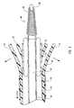
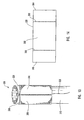
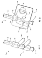
- delivery device 10 includes a guide member 12 having a distal end 14 and a proximal end 16.
- guide member can refer to any structure that is capable of functioning as a guidewire that can be steered through the tortuous anatomy of a patient. It will be appreciated that guide member 12 can be hollow or partially hollow depending upon design considerations.
- Distal end 14 of guide member 12 includes a tip 15 that is configured for percutaneous insertion into a body lumen, while proximal end 16 either includes or is adapted to cooperate with an actuating assembly 20 that is adapted to deploy dilation assembly 40 and/or stent 42.
- guide member 12 can have an outside diameter of between about 0,25 mm (0.010 inches) to about 16,5 mm (0.650 inches) and an inside diameter or diameter of lumen 18 from about 0,1 mm (0.004 inches) to about 14 mm (0.55 inches).
- guide member 12 can be fabricated from a variety of different materials.
- guide member 12 can be fabricated from Nitinol, steel, metals, metal alloys, composites, plastic, polymers, synthetic materials, such as, but not limited to, PEEK, Rydel, or combinations thereof.
- guide member 12 can have the configuration of a braid-reinforced polymer tube or a rigid polymer tube.
- guide member 12 can be covered with one or more coatings.
- guide member 12 can include one or more coatings that improve lubricity, reduce platelet aggregation, or have anti-thrombogenic properties.
- guide member 12 can include one or more hydrophilic coatings, heparinized coatings, Polytetrafluoroethylene (PTFE) coatings, silicone coatings, combinations thereof, or other coatings that may aid with positioning guide member 12 and/or preventing damage to the body lumen.
- PTFE Polytetrafluoroethylene
- guide member 12 may include one or more cuts, slits, grooves, or other structures, illustratively identified by numeral 17, that provide flexibility to all or a portion of guide member 12.
- cuts, slits, or grooves to provide flexibility, it can be appreciated by one skilled in the art that guide member 12 or other portion of device 10 may have a lattice structure, i.e., portions of guide member 12 or device 10 removed therefrom, which provides flexibility to a portion of guide member 12 and/or other portion of device 10.
- the cuts, slits, or grooves can be located at any location of guide member 12 and may have various pitches to allow or provide for different flexibilities. These one or more grooves, cuts or slits can partially or completely extend through portions of guide member 12. Additionally, these grooves, cuts, or slits can have a variety of different configurations, such as but not limited to, straight, helical, geometric, combinations thereof, or various other configurations known to those skilled in the art, so long as those same provide flexibility to guide member 12. Further, any number of grooves, cuts, or slits can be included in guide member 12 and optionally portions of dilation assembly 40.
- each groove, cut, or slit can vary depending upon the desired flexibility. For instance, the deeper the groove, cut, or slit, the greater the flexibility of guide member 12, and hence delivery device 10. Furthermore, differences in the configuration of each groove, cut, or slit can affect the flexibility of guide member 12 and therefore delivery device 10. For instance, the steeper the sides of a particular groove, cut, or slit, the less flexibility provided to guide member 12 and/or delivery device 10.
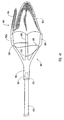
- Figure 1 depicts dilation assembly 40 and stent 42 ( Figure 2 ) disposed at tip 15 of guide member 12.
- Dilation assembly 40 terminates in an atraumatic tip 48.
- Dilation assembly 40 and stent 42 are retained at tip 15 of guide member 12 by a restraining mechanism or restraining member 25.
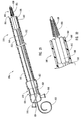
- an actuating member 28 operates restraining member 25 and extends to an actuating assembly 20 disposed at a proximal end of device 10.
- Actuating member 28 extends to the proximal end of device 10 and is exposed to allow the restraint applied by restraining member 25 to be released as a clinician moves actuating member 28 in a proximal direction.
- actuating member 28 can optionally extend outside guide member 12 to proximal end 16 of device 10.
- Dilation assembly 40 is connected to a dilation tube 44 that extends along the length of guide member 12.
- Dilation tube 44 is used to fill a dilation balloon 46 with a fluid.
- the fluid may be introduced through a luer lock fitting 45 located at proximal end 16 of guide member 12.
- Dilation tube 44 may also be used, in some embodiments, as a positioning member for deploying dilation assembly 40 and stent 42.
- dilation assembly 40 of device 10 is coupled by dilation tube 44 to actuating element 21. By sliding actuating element 21 with respect to proximal end 16 of guide member 12, dilation assembly 40 is moved with respect to guide member 12 and can be deployed from tip 15 of guide member 12.
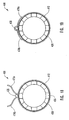
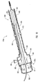
- distal end 14 of guide member 12 includes one or more struts 24 that are adapted to retain dilation assembly 40 and stent 42 within lumen 18 until the same are to be deployed.
- Each strut 24 can be biased to extend outwardly to release dilation assembly 40 and stent 42.
- each strut 24 need not be biased to extend outwardly.
- the one or more struts 24 can be formed using a variety of different processes.
- the processes can include, but not limited to, machining processes performed using a laser or conventional machining process, including, but not limited to, hydro-machining, grinding, end milling, slitting saws, abrasive saws, electrical discharge machines, combinations thereof, or other machining processes capable of creating slots or slits sufficient to form one or more struts 24.
- each strut 24 can be formed integrally with guide member 12.
- one or more of struts 24 are formed as part of a discrete strut assembly that is attached to guide member 12.
- restraining member 25 Surrounding struts 24 is restraining member 25.
- restraining member 25 is a sleeve 26.
- Sleeve 26 is adapted to retain or maintain struts 24 in a restrained or closed configuration so that the combination of sleeve 26 and struts 24 maintain dilation assembly 40 and stent 42 within lumen 18.
- Sleeve 26 is adapted to cooperate with the exterior of guide member 12 so that sleeve 26 can be displaced in a proximal direction to release struts 24. Since struts 24, in this exemplary configuration, are biased to extend outwardly, upon moving sleeve 26 in a proximal direction, struts 24 extend outwardly to release dilation assembly 40 and stent 42.
- Sleeve 26 can be fabricated from various types of materials so long as sleeve 26 is capable of securely retaining struts 24.
- sleeve 26 can be fabricated from heat shrink synthetic material, including but not limited to, low-density polyethylene (LDPE), polyethylene terphthalate (PET), Polytetrafluoroethylene (PTFE), fluorinated ethylene propylene (FEP), polyethylene (PE), polyurethane (PU), silicone tubing, and other suitable polymers or synthetic materials.
- LDPE low-density polyethylene
- PET polyethylene terphthalate
- PTFE Polytetrafluoroethylene
- FEP fluorinated ethylene propylene
- PE polyethylene
- PU polyurethane
- silicone tubing and other suitable polymers or synthetic materials.
- Actuating member 28 extends from sleeve 26, travels along an exterior of guide member 12, and passes through an aperture 30 in guide member 12. Actuating member 28 continues to travel within lumen 18 of guide member 12 until it reaches proximal end 16 of guide member 12. It will be appreciated that in other embodiments, actuating member 28 may remain external to lumen 18 of guide member 12.
- Actuating member 28 can be fabricated from various materials and have various configurations so long as it is capable of performing the function of displacing sleeve 26.
- actuating member 28 can be fabricated from plastics, polymers, metals, composites, alloys, synthetic materials, and combinations thereof.
- dilation assembly 40 includes a dilation balloon 46 mounted to a dilation tube 44.
- Dilation tube 44 extends from distal end 14 of guide member 12 toward proximal end 16 of guide member 12.
- Dilation tube 44 can include a plurality of holes 50.
- Each hole 50 and/or plurality of holes 50 in combination provide a fluid path to an interior 52 of dilation balloon 46. In this way, fluid may pass along a lumen 54 of dilation tube 44 to flow into dilation balloon 46.
- atraumatic tip 48 seals the distal end of dilation tube 44.
- holes 50 provide a fluid path to deflate dilation balloon 46 or remove the fluid to deflate dilation balloon 46.
- Each hole 50 can have various configurations so long as each hole 50 is capable of allowing fluid to pass therethrough.
- Dilation tube 44 in one configuration, is an internal support for dilation balloon 46 and stent 42.
- Dilation tube 44 can be fabricated from Nitinol, steel, metals, metal alloys, composites, plastic, and combinations thereof. Further, dilation tube 44 can be covered with a variety of different coatings, such as, but not limited to, one or more coatings to improve lubricity, anti-thrombogenic properties, and reduce platelet aggregation. Other coatings can include, but not limited to, hydrophilic coatings, heparinized coatings, Polytetrafluoroethylene (PTFE) coating, silicone coating, or combinations of the coatings described herein.
- PTFE Polytetrafluoroethylene
- Dilation tube 44 may have a variety of different configurations and embodiments.
- dilation tube 44 includes a proximal end where provision is made for connecting dilation tube 44 to an inflation device with an annular clamping device, such as a touhy-borst adaptor.
- a proximal end of dilation tube 44 has the form of a luer fitting, whether the male or female part of the luer fitting.
- atraumatic tip 48 Mounted to a distal end of dilation tube 44 is an atraumatic tip 48.
- Atraumatic tip 48 is disposed within lumen 54 of dilation tube 44 and seals dilation tube 44, prevents fluid from escaping therefrom during inflation and deflation of dilation balloon 46, and provides a flexible tip that aids in positioning and steering of delivery device 10 through the tortuous anatomy of the patient.
- dilation tube 44 extends to a distal end of dilation balloon 46 and atraumatic tip 48 is disposed therein.
- dilation tube 44 can extend to a position proximal to the distal end of dilation balloon 46 and a portion of atraumatic tip 48 then extends from a distal end of dilation tube 44 to a position distal to the distal end of dilation balloon 46.
- dilation tube 44 terminates within a lumen formed in atraumatic tip 48.
- Atraumatic tip 48 includes a core 56 that is surrounded by a flexible coil 58. As shown, flexible coil 58 terminates at a distal end of tip 48 with an atraumatic portion, such as a solder ball or other mechanism for forming an atraumatic distal end of tip 48. More generally, atraumatic tip 48 can have a variety of other configurations so long as atraumatic tip is flexible and optionally shapeable. Furthermore, atraumatic tip 48 may be radiopaque to allow steerable positioning of delivery device 10 while allowing a physician or clinician to observe the location of tip 48 using appropriate devices, such as a fluoroscopic device or X-ray device.
- Materials that facilitate or provide radiopacity may include, but not limited to, platinum, alloys of platinum, gold, or combinations thereof, metals, alloys, plastic, polymer, synthetic material, combinations thereof, or other materials that provide an appropriate radiopaque signature, while capable of being shaped by a physician or clinician.
- tip 48 can be a polymer that is dipped or coated with an appropriate radiopaque material, such as, but not limited to, barium sulphate, bismuth subcarbonate, titanium dioxide, or combinations thereof.
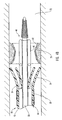
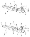
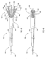
- distal end 14 of delivery device 10 upon disposition of sleeve 26 in a proximal direction.
- dilation assembly 40 and stent 42 can be deployed from within lumen 18. Deploying of dilation assembly 40 and stent 42 can occur as guide member 12 is displaced in a proximal direction, dilation tube 44 is displaced in a distal direction, or a combination of proximal and distal movements of guide member 12 and dilation tube 44 respectively.
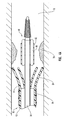
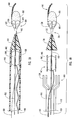
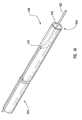
- FIG. 4a schematically depicted is delivery device 10 in a deployed configuration where dilation assembly 40 and stent 42 have been deployed at a lesion 70 of a body lumen 72.
- Deployment of dilation assembly 40 and stent 42 can be achieved through manipulating actuating assembly 20 ( Figures 1 and 2 ).
- fluid can be introduced through lumen 54 of dilation tube 44 to expand dilation balloon 46 and therefore deploy or force stent 42 into body lumen 72 and surrounding lesion 70, as is illustrated in Figure 5 .
- stent 42 Various configurations of stent 42 are known to those skilled in the art.
- an expandable stent may be used that automatically opens under the pressure of dilation balloon 46.
- a self-expanding stent can be used, as illustrated in Figure 4b with dotted lines. The self-expanding stent automatically opens as the restraining force applied by struts 24 and/or restraining member 25 is removed and guide member 12 is moved proximal to the stent.
- the self-expanding stent surrounds dilation balloon 46, as illustrated in Figure 4b , or alternatively, the stent can surround dilation tube 44 with dilation balloon 46 being located proximal to the stent and still mounted to dilation tube 44, as illustrated by dotted lines referenced by numeral 46b.
- Various stents may be used with the present invention, so long as the stent can be reduced in size to surround the dilation balloon and be disposed within guide member 12 of delivery device 10.
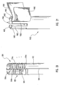
- actuating assembly 20 that can be used to deploy dilation balloon 46 and stent 42.
- Operating actuating assembly 20 releases dilation assembly 40 and stent 42 from a restrained configuration at distal end 14 of guide member 12. More specifically, dilation balloon 46 forming part of dilation assembly 40 can be deployed with stent 42 being disposed substantially around dilation balloon 46.
- actuating assembly 20 includes an actuating element 21 coupled to a proximal end of dilation tube 44.
- Actuating element 21 includes a distal end 74 configured to be mounted to and cooperate with proximal end 16 of guide member 12.
- a proximal end 76 of actuating element 21 is attached to a proximal end of dilation tube 44, while a proximal end of actuating member 28 passes through a sealed aperture 47 of actuating element 21.
- the proximal end of dilation tube 44 includes a luer fitting 45 that allows various complementary luer fittings to be attached thereto.
- a syringe (not shown) can be attached to luer fitting 45 for introducing fluid to and removing fluid from dilation balloon 46 ( Figure 5 ) during inflation and deflation of dilation balloon 46.
- luer fitting 45 it can be understood by one skilled in the art that various other configurations of fitting can be attached to or formed at the proximal end of dilation tube 44.
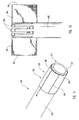
- Actuating element 21 is adapted to be displaced in a distal direction to deploy dilation assembly 40 and stent 42.
- distal end 74 can have a step configuration and include protrusions 78 that mate with complementary indentations 80 formed in proximal end 16 of guide member 12.
- the protrusions 78 and indentations 80 provide an indication of the relative position of dilation assembly 40 and stent 42 relative to distal end 14 of guide member 12. Therefore, actuating element 21 and/or guide member 12 can include one or more protrusions and indentations. As actuating element 21 is displaced in a distal direction, protrusions 78 mate with indentations 80.
- each seal 84 surround protrusions 78. Additionally, one or more seals (not shown) can surround dilation tube 44 and/or actuating member 28. Illustratively, each seal can be one or more O-rings in one or more grooves, one or more O-rings, a gasket, or a viscous fluid seal.
- actuating element 21 When actuating element 21 is displaced in the distal direction, distal end 74 contacts a wall or stop 82 formed in guide member 12 that prevents further displacement of actuating element 21 in the distal direction. Through this configuration, actuating element 21 is prevented from excessive longitudinal displacement in the distal direction. This stopping of the longitudinal displacement of actuating element 21 indicates that dilation balloon 46 and stent 42 are deployed from within lumen 18 of guide member 12 to the desired position for expanding or implanting stent 42.
- a plurality of indentations and/or protrusions can be included within actuating element 21 and guide member 12 to control the distance which actuating element 21 and, consequently, stent 42 is displaced.
- a wall or stop formed in actuating element 21 can mate with the distal end of guide member 12 to prevent excessive longitudinal displacement in the distal direction.
- a combination of one or more walls or stops in actuating element 21 and guide member 12 can be used.
- distal end 74 of actuating element 21 can be tapered and cooperate with a taper formed in proximal end 16 of guide member 12.
- the complementary tapers control the longitudinal displacement of actuating element 21 relative to proximal end 16 of guide member 12.
- a combination of indentations, protrusions, walls, stops, threads, or tapers can be used.
- Various other manners are known to control the distance traveled by actuating element 21 while indicating the position of stent 42.
- actuating element 21 can include one or more elements, such that wall or stop 82 and indentations 80 are formed in separate elements or members that are attached or coupled to proximal end 16 of guide member 12. By so doing, actuating element 21 can be fabricated separately from guide member 12, thereby reducing costs and expenses associated with fabricating proximal end 16 of guide member 12 in the desired configuration.
- Figures 7 through 24 illustrate alternative embodiments for restraining mechanism 25. It will be appreciated that many features of the delivery devices depicted in Figures 7 through 24 are substantially similar in structure and function as for delivery device 10. Consequently, features and functions of one embodiment of the present invention are applicable to other embodiments of the present invention.
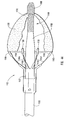
- a guide member 112 which can be similar to the other guide members described herein, has a distal end 114, a proximal end (not shown), and a lumen 118 extending from distal end 114 to the proximal end.
- a tip 115 of guide member 112 includes a plurality of struts 124, such as two or more struts.
- Each strut 124 can be optionally biased so that a distal end of each strut 124 moves outwardly from a longitudinal axis of guide member 112 when each strut 124 is released by a restraining member 125.
- each strut 124 being biased, one skilled in the art can appreciate that one or more of struts 124 can be biased.
- At least one strut is biased toward the longitudinal axis of guide member 112.
- atraumatic tip 148 Disposed upon strut 124a, as more clearly seen in Figure 7 , is an atraumatic tip 148.
- This atraumatic tip 148 either alone or in combination with strut 124a, may be shapeable by a physician or clinician before insertion into a body lumen. In this manner, the physician or clinician is able to configure tip 148 with an appropriate shape, such as, but not limited to a "J" shape, which enables guide member 112 to be guided through the tortuous anatomy of a patient.
- All or a portion of atraumatic tip 148 can be fabricated from platinum, platinum alloys, radiopaque materials, materials doped or coated with a radiopaque material, metals, alloys, plastic, polymer, synthetic material, combinations thereof, or other materials that provide an appropriate radiopaque signature, while are capable of being shaped, whether alone or in combination with strut 124a, by a physician or clinician.
- a guidewire with an associated dilation assembly can be disposed within lumen 118, with a distal end of the guidewire optionally including a flexible atraumatic tip, since atraumatic tip 148 can function as the atraumatic tip for delivery device 100.
- restraining member 125 surrounds struts 124.
- the restraining member 125 and other restraining members or mechanisms described herein are examples of means for applying a restraining force upon one or more struts or means for applying a restraining force upon a distal end of a guide member.
- restraining member 125 can extend completely or partially from the distal end to the proximal end of guide member 112.
- restraining member 125 can surround substantially only struts 124 or can have a configuration similar to those depicted in Figures 9-24 .
- restraining member 125 or means for applying a restraining force is a catheter 127 that applies a force against struts 124 to prevent struts 124 from extending outwardly or applies a force against struts 124 to maintain a dilation assembly 140 and a stent 142 in lumen 118.
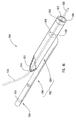
- the force applied to struts 124 is released and, in one configuration, the distal ends of struts 124 are allowed to move outwardly to allow dilation assembly 140 and stent 142 to be deployed.
- catheter 127 can extend completely or partially the length of the guide member.
- catheter 127 can be replaced with a sleeve or other structure that completely or partially extends toward the proximal end of guide member 112 from the distal end.
- These alternate configurations are also means for applying a restraining force, as described herein.
- These restraining members or mechanisms can be radiopaque or include one or more radiopaque markers that aid with positioning the device.
- these restraining members or mechanisms can be slidable relative to the guide member using an actuating member and/or an actuating assembly disposed on an exterior of the guide member, within a lumen of the guide member, or partially within the lumen and partially on the exterior of the guide member.
- the actuating assembly may be similar in structure and function to actuating assembly 20 described in Figure 6 or any other actuating assembly described herein. Therefore, systems, methods, and devices of the present invention can optionally use catheters, sleeves, bands, or other structures described herein interchangeably to perform the desired function of restraining one or more struts or a distal end of the guide member.
- FIGS 9 and 10 depict another embodiment of a delivery device 200 of the present invention.
- delivery device 200 includes a guide member 212 with a plurality of struts 224 disposed at a distal end 214 thereof. Struts 224 are maintained in a restrained position using a restraining member 225.
- restraining member 225 is a sleeve 226 surrounding struts 224.
- Sleeve 226 acts as a restraining member or mechanism that applies a force against the struts to prevent the struts from extending outwardly or to maintain the dilation balloon and/or stent within the lumen.
- Struts 224 when in a restrained position, maintain dilation assembly 240 and stent 242 within lumen 218 of guide member 212.
- actuating members 228 Disposed within sleeve 226 or between sleeve 226 and guide member 212 are one or more actuating members 228.
- Actuating members 228, optionally forming part of the restraining mechanism or member, are attached to guide member 212 at a location proximal to the proximal end of each strut 224, identified by letter A.
- Actuating members 228 extend distally to the distal end of sleeve 226 and subsequently extend proximally on the outside of sleeve 226 to terminate at the proximal end (not shown) of device 200.
- each actuating member 228 is located at the proximal end of sleeve 226, whether forming part of sleeve 226, attached to sleeve 226, attached to guide member 212, or combinations thereof, displacing actuating member 228 in the proximal direction causes actuating member 228 to preferentially separate sleeve 226 into one or more portions 232, illustrated in dotted lines. By so doing, struts 224 are released, as illustrated in Figure 10 .
- a proximal end (not shown) of actuating member 228 extends to a proximal end (not shown) of guide member 212, either within or without lumen 218 of guide member 212.
- Actuating members 228 can extend to an actuating element (not shown) of an actuating assembly, such as, but not limited to, the actuating assembly of Figure 6 and other actuating assemblies described herein and understood by one skilled in the art in light of the teachings contained herein.
- the actuating member 228 can be displaced in the proximal direction relative to guide member 212. By so doing, the restraining force applied by sleeve 226 is released, struts 224 extend outwardly, and dilation assembly 240 and/or stent 242 are deployed.
- Sleeve 226 can be formed from a variety of different materials, so long as the material is sufficiently strong to secure struts 224, while being configured to preferentially separate under the action of actuating members 228.
- sleeve 226 can be fabricated from heat shrink synthetic material, including but not limited to, low-density polyethylene (LDPE), polyethylene terphthalate (PET), Polytetrafluoroethylene (PTFE), fluorinated ethylene propylene (FEP), polyethylene (PE), polyurethane (PU), or silicone tubing.
- LDPE low-density polyethylene
- PET polyethylene terphthalate
- PTFE Polytetrafluoroethylene
- FEP fluorinated ethylene propylene
- PE polyethylene
- PU polyurethane
- the one or more actuating members 228 can be formed from a variety of different materials, so long as the material used is sufficiently strong to allow an actuating assembly, such as, but not limited to, those actuating assemblies disclosed herein, to displace actuating member 228 proximally without breaking the same.
- actuating members 228 can be fabricated from plastics, polymers, metals, composites, alloys, synthetic materials, and combinations thereof.
- sleeve 226 can have dissolvable chemical bonds which dissolve due to a chemical reaction with the fluid in the body lumen within which the delivery device is disposed, bonds that are broken through applying resistive heating, ultrasonic, or radio frequency energy to actuating members 228 and/or region of the body lumen containing device 200, preferential tear or cut regions or zones where the material has a weaker strength than other regions or zones of the sleeve, or combinations thereof.
- restraining member 325 is in the form of a sleeve 326 which is adapted to surround one or more struts 324 of a guide member 312 and apply a restraining force against struts 324 to maintain struts 324 in a restrained configuration.
- Sleeve 326 includes a first side 364 and a second side 366 with first and second sides 364, 366 being separated by an intermediate portion 368.
- Intermediate portion 368 surrounds guide member 312 in such a manner that portions of intermediate portion 368 contact, are juxtaposed to, are contiguous with, or are adjacent to one another.
- An actuating member 328 passes through such portions of intermediate portion 368 to secure sleeve 326 upon guide member 312.
- first side 364 and second side 366 are folded to attach to respective portions of outside surface of sleeve 326.
- Figures 12 and 13 The process of forming the restraining member or mechanism of Figure 11 is illustrated in Figures 12 and 13 .
- sleeve 326 can be directly formed on guide member 312 or can be formed on a separate tubular member and subsequently attached or coupled to guide member 312.
- Sleeve 326 is illustrated as having a generally polygonal configuration, however, one skilled in the art can appreciate that sleeve 326 can have various other configurations so long as it is capable of performing the functions described herein. In this exemplary configuration, sleeve 326 is coupled directly to guide member 312.
- First side 364 and second side 366 of sleeve 326 are wrapped around at least a portion of guide member 326, until a portion of intermediate portion 368 is in close proximity with another portion of intermediate portion 368, as illustrated in Figure 13 .
- a first side 364 can contact second side 366 or be juxtaposed, contiguous, or adjacent to second side 366.
- actuating member 328 When the portions of intermediate portion 368 are in close proximity, actuating member 328, or alternatively some other actuating member, is stitched through both portions of sleeve 326 to couple the portions of intermediate portion 368, as shown in Figure 13 .
- actuating member 328 is drawn substantially straight or otherwise positioned through sleeve 326, first end 364 and second end 366 are respectively folded to attach to respective outside surfaces of sleeve 326, as shown in Figure 11 .
- sleeve 326 can include a plurality of apertures 360 on portions of intermediate portion 368 that receive actuating member 328. In this manner, actuating member 328 can pass through apertures 360 rather being stitched through sleeve 326.
- first end 364 of sleeve 326 can be coupled to second end 364 of sleeve 326 without attaching first end 364 or second end 366 to the outside surface of sleeve 326.
- a portion of first end 364 can overlap a portion of second end 366, or vice versa.
- first end 364 and second end 366 contact each other but do not overlap.
- first end 364 and second end 366 can be adjacent to one another, adjoining one another, contiguous to one another, or juxtaposed to one another.
- a proximal end of actuating member 328 extends to a proximal end of guide member 312, either within or without a lumen of the guide member 312.
- actuating member 328 is released from being disposed through at least a portion of sleeve 326.
- the restraining force applied by sleeve 326 is released, struts 324 extend outwardly, and the dilation assembly and/or stent are deployed.
- a clinician or physician can initiate the longitudinal motion of actuating member 328, either directly or through using of an actuating mechanism or device.
- Sleeve 326 can be formed from a variety of different materials, so long as the material is sufficiently strong to restrain one or more struts 324.
- sleeve 326 can be fabricated from various types of polymer or silicone films, such as but not limited to, heat shrink plastic, polymer, low-density polyethylene (LDPE), polyethylene terphthalate (PET), Polytetrafluoroethylene (PTFE), fluorinated ethylene propylene (FEP), polyethylene (PE), polyurethane (PU), or silicone tubing.
- LDPE low-density polyethylene
- PET polyethylene terphthalate
- PTFE Polytetrafluoroethylene
- FEP fluorinated ethylene propylene
- PE polyethylene
- PU polyurethane
- Actuating member 328 can be formed from a variety of different materials, so long as the material used is sufficiently strong to allow the actuating assemblies disclosed herein to displace actuating member 328 proximally without breaking actuating member 328.
- actuating member 328 can be fabricated from plastics, polymers, metals, composites, alloys, synthetic materials, combinations thereof, or other material that is capable of performing the function of being disposed through sleeve 326 and capable of being withdrawn therefrom.
- a delivery device 400 having an alternate configuration of a restraining member or mechanism.
- This particular embodiment utilizes a restraining member or mechanism 425 having a hinged configuration with an actuating member 438, optionally forming part of restraining member or mechanism 425, acting as the pin to maintain the hinged portions of the restraining member in a configuration that retains or restrains a portion of the guide member.
- restraining member 425 is a sleeve 426 having a plurality of channels 464a-464f that are adapted to receive actuating member 428. Both a first side 466 and a second side 468 of sleeve 426 are formed with some of channels 464a-464f, i.e., channels 464a, 464c, and 464e on first side 466 and channels 464b, 464d, and 464f on second side 468.
- first side 466 is coupled to second side 468 and sleeve 426 applies a restraining force against struts 424 of guide member 412.
- FIG. 16 An exemplary process of forming the restraining member or mechanism of Figure 15 is illustrated in Figures 16-19 .
- sleeve 426 includes a number of extensions or tongues 460a-460f. These extensions 460a-460f are configured to form channels 464a-464f and surround a tubular member or tube, such as, but not limited to, a guide member 412 within which actuating member 428 is located.
- sleeve 426 To attach sleeve 426 to guide member 412, sleeve 426 is positioned over the desired portion of guide member 426. Actuating member 428 is placed in close proximity to guide member 412, as shown in Figures 17-19 . The ends of the extensions 460a-460f are inserted between guide member 412 and actuating member 428, as shown in Figure 18 . Alternatively, extensions 460a-460f can be partially wrapped around guide member 412 and actuating member 428 placed into contact with these partially wrapped extensions 460a-460f.
- each extension 460a-460f is pulled tightly around guide member 412 and actuating member 428, an end of each extension 460a-460f is folded over actuating member 428 to attach to the outer surface of sleeve 426, as shown in Figures 15 and 19 .
- channels 464a-464f are formed and sleeve 426 is configured with actuating member 428 to releasably restrain struts 424 of guide member 412.
- Releasing the restraining force applied by sleeve 426, alone or in combination with actuating member 428, is achieved through displacing actuating member 428 longitudinally with respect to guide member 412, vice versa, or combination thereof.
- Actuating member 428 is released from channels 464a-464f to allow the biasing force of struts 424 to extend the struts outwardly to deploy dilation assembly and/or stent.
- a clinician or physician can initiate the longitudinal motion of actuating member 428, either directly or through using of an actuating mechanism or device.
- FIG. 20 depicted is another delivery device 500 having another embodiment of a restraining member or mechanism 525 of the present invention.
- the restraining member 525 includes a cord 529 forming a number of hoops 564a-564n.
- One or more of hoops 564a-564n are adapted to receive an actuating member 528, which is optionally part of restraining member or mechanism 525.
- the actuating member 528 is disposed within hoops 564a-564n so that cord 529 applies a restraining force against struts 524 of guide member 512.
- Actuating member 528 can be removed from hoops 564a-564n to thereby allow struts 524 to extend outwardly to deploy the dilation assembly and/or stent.
- Cord 529 may be made from metallic wires, polymer actuating members, or other materials that can be manipulated to form hoops through which an actuating or securing member.
- cord 529 is adapted to expand outwardly either under the influence of one or more struts or due to a biasing force applied or incorporated within cord 520 by the configuration and/or material of the cord, the hoops, and/or the restraining member.
- Cord 529 can be attached to guide member 512 and/or one or more of the struts associated therewith through various attachment mechanisms.
- cord 529 can be attached to guide member and/or one or more of the struts through adhesives, mechanical fasteners, securing loops, or other manner that securely attaches cord 529 to guide member 512 and/or one or more of struts 524.
- cord 529 may be attached to actuating member 528 and be removed when actuating member 528 is moved in a proximal direction. A clinician or physician can initiate the longitudinal motion of actuating member 528, either directly or through using of an actuating mechanism or device.
- a guide member 612 includes a plurality of struts 624 that are adapted to extend outwardly to enable deployment of the stent and dilation balloon disposed within a lumen 618 of guide member 612.
- a restraining member 625 restrains struts 624.
- This restraining member 625 in one configuration, is a flexible member 627 configured with flaps 660 and 662.
- the flaps 660 and 662 extend between a gap 664 between the two adjacent struts 624a and 624b and are adapted to be pulled around struts 624 to compress stent (not shown) and dilation balloon (not shown) within lumen 618, as illustrated in Figure 23 .
- These flaps 660 and 662 can be two separate members that are bonded or otherwise connected to struts 624a and 624b or a single member that is coupled to struts 624a and 624b while forming flaps 660 and 662.
- flaps 660 and 662 When flaps 660 and 662 have been positioned to securely retain struts 624, they are then stitched together at a location 666, identified in Figure 23 , with an actuating member 628.
- This actuating member 628 optionally forming part of the restraining member or mechanism, extends the length of delivery device 600 toward an actuating assembly, such as, but not limited to, the actuating assembly described in Figure 6 and other actuating assemblies known to those skilled in the art in light of the teachings contained herein.
- a clinician or physician can initiate longitudinal motion of actuating member 628 to release restraining member or mechanism 625, either directly or through using of an actuating mechanism or device as known to those skilled in the art.
- flaps 660 and 662 are folded back around struts 624 and the remainder of flaps 660 and 662, and then attached to struts 624, or other portion of guide member 612, as illustrated in Figure 24 .
- actuating member 628 is displaced in a proximal direction, flaps 660 and 662 are released and stent (not shown) and dilation balloon (not shown) are deployed as struts 624 extend outwardly.
- FIG. 25 depicted is an illustrative embodiment of a proximal end of a delivery device 700a.
- the features and structures discussed with other embodiments of the delivery device of the present invention apply to delivery device 700a.
- a proximal end 716 of a guide member 712 terminates in a guide member housing 722.
- This guide member housing 722 can be integrally formed with guide member 712 or alternatively be a separate member coupled, connected, or attached to a proximal end of guide member 712.
- Proximal end 716 of guide member 712 is coupled to an actuating element 721 of an actuating assembly 720.
- This actuating element 721 slidably engages with guide member housing 722.
- Manipulation of actuating element 721 effects the movement of dilation tube 744 upon which is mounted the dilation balloon (not shown).
- Actuating member 728 extends through an aperture 786 in actuating element 721 that is adapted with a seal (not shown) through which actuating member 728 can slide.
- aperture 786 and the seal (not shown) allow access for the operator to release or displace the restraining member (not shown) that restrains the one or more struts (not shown) disposed at distal end 714 of delivery device 700a.
- the seal can include a polymer gasket, such as, but not limited to, polyurethane, silicone rubber, or other materials that are capable of making a seal around actuating member 728 and allow the actuating member 728 to slide therethrough while a fluid seal is maintained.
- a dilation tube 744 extends from a distal end 714 of guide member 712 through guide member housing 722 to terminate and be attached to proximal end 776 of actuating element 721.
- proximal end 776 of actuating element 721 includes a luer fitting 745, which is adapted to cooperate with a complementary luer fitting for inflating and deflating a dilation balloon (not shown) disposed at distal end 714 of guide member 712.
- an additional luer fitting 790 is formed in or coupled to actuating element 721.
- Luer fitting 790 is provided to infuse fluid through a lumen 718 of guide member 712, thereby allowing introduction of a contrast media in the blood flow around the vicinity of the device as it is advance in the vasculature.
- FIG. 26 an alternate configuration of delivery device 700a is depicted as illustrated delivery device 700b.
- the engagement between actuating element 721 and guide member housing 722 can be achieved through complementary threads 792 formed in actuating element 721 and guide member housing 722.
- These complementary threads 792 can be configured to allow longitudinal movement of actuating element 721 relative to guide member housing 722 through rotational motion of actuating element 721 or motion parallel to the longitudinal axis of guide member 712.
- threads 792 very precise control of the longitudinal movement of the dilation balloon (not shown) and stent (not shown) disposed at distal end 714 of guide member 712 can occur.
- actuating element 721 can include a key that mates with a key way formed in guide member housing 722, or vice versa.
- rotational motion and motion parallel to the longitudinal movement of the dilation balloon and stent one skilled in the art can identify various other directions of motion that can enable or facilitate deployment of the dilation balloon and/or stent.
- the motion of actuating element can be at any angular orientation relative to the longitudinal axis of the guide member, whether or not such motion includes one or more revolutions of the actuating element relative to the guide member.
- actuating element 721 and guide member housing 722 and/or guide member 712 can include optional handles 796 and 798 respectively.
- These handles 796 and 798 can optionally include gripping regions that are adapted to cooperate with one or more appendages of a user of the device.
- each handle 796 and 798 can have a substantially constant cross-section along their lengths.
- each handle 796 and 798 can have variable cross-sections along their lengths.
- delivery device 700c can include one or more fittings to facilitate introduction of one or more fluids to an interior of delivery device or to a dilation balloon.
- Figure 28 shows yet another embodiment of delivery device 700d in which actuating element 721 includes a housing 760 that contains a rotatable gear 762 adapted to cooperate with complementary features or structures 770 formed in a proximal end of guide member 712.
- the gear 762 with associated one or more teeth, features or structures 768, can be manipulated or rotated by an actuator 764 as a clinician or other individual selects an actuator member 766 and rotates actuator 764 to rotate gear 762.
- actuator 764 has one or more teeth, features or structures that can cooperate with gear 762, such that rotational motion of actuator 764 is translated to movement of gear 762.
- the complementary features 770 of guide member 712 mate with the teeth, features or structures 768 of gear 762 to move guide member 712 in a proximal and/or distal direction, dependent upon the rotational direction of actuator 764.
- the dilation assembly and the stent can be deployed from a distal end (not shown) of device 700d.
- actuating member 728 may also be operated through using a sliding switch 762 associated with housing 760 and actuating element 721.
- the actuating member 728 is coupled to a leg 762 that is attached to switch 762, while sliding switch 762 is slidably coupled to housing 760.
- the sliding translation of switch 762 moves actuating member 728 in the respective direction to release a restraining force applied by the restraining member or mechanism (not shown) of device 700c.
- FIG. 29-37 depicted are various configurations of alternative embodiments of a delivery device in accordance with the present invention.
- the features and functions of other described delivery devices apply to the discussion of delivery devices 800a through 800g.
- the majority of features and functions described with respect to delivery device 800a also apply to delivery devices 800b through 800g described further below.
- the delivery devices of Figures 29-37 illustrate various embodiments wherein a delivery device is adapted to be used with a guidewire.
- the embodiments of Figures 29-37 do not include a restraining member or mechanism that restrains the dilation assembly and stent inside the guide member.
- any restraining member or mechanism with any actuating assembly may be employed with devices 800a-800g.
- delivery device 800a includes a guide member 812 having a proximal end 816 and a distal end 814, with a lumen 818 extending from distal end 814 toward proximal end 816.
- the distal end 814 can have a similar configuration to the other guide member distal ends described herein.
- a restraining member (not shown) may be disposed at distal end 814 to cooperate with structures adapted to restrain a dilation assembly 840 and/or a stent 842.
- a guide member housing 822 Disposed at proximal end 816 is a guide member housing 822 that cooperates with an actuating element 821 of an actuating assembly 820, in a similar manner to that described with respect to Figure 6 .
- dilation assembly 840 Extending from an aperture 834 in a proximal end of actuating element 821 toward distal end 814 of guide member 812 is a guidewire 832.
- guidewire 832 cooperates with a dilation assembly 840 disposed at a distal end of guide member 812.
- dilation assembly 840 includes a tubular member 836 that cooperates with a dilation balloon 846 coupled or attached thereto.
- the tubular member 836 can function as a positioning member that facilitates deployment of dilation assembly 840 and stent 842.
- the guidewire 832 extends through tubular member 836 that allows dilation balloon 846, and a stent 842 coupled to dilation balloon 846, to be moved along guidewire 832 when necessary.
- the internal diameter of a lumen of tubular member 836 is complementary to the exterior diameter of guidewire 832.
- Guidewire 832 terminates at a distal end with an atraumatic tip 848 that can include a core wire 856 wrapped with a coiled spring 858.
- the core wire 856 may be an extension of the remainder of guidewire 832 or alternatively may be a separate member coupled or attached to the distal end of guidewire 832. In either case, core wire 856 can be made from the same or a different material than guidewire 832 and may optionally be a solid member or a tubular member.
- the dilation balloon 846 of dilation assembly 840 is inflated through a dilation tube 844 that extends from dilation balloon 846 to terminate at the proximal end of actuating element 821 with a luer fitting 845.
- An additional luer fitting 890 may be provided attached to actuating element 821. It will be appreciated that luer fitting 890 can perform substantially the same function as luer fitting 790.
- the distal end of dilation tube 844 cooperates with an interior of dilation balloon 846.
- the distal end of dilation tube 84 can be connected to tubular member 836, dilation balloon 846, or to both tubular member 836 and dilation balloon 846.
- the dilation tube 844 can be used to position dilation balloon 846 and/or stent 842 during a procedure. Consequently, dilation tube 844 can have sufficient strength to enable distal movement of dilation tube 844 to translate to distal movement of the remainder of dilation assembly 840. Similarly, dilation tube 844 can have sufficient strength to enable proximal movement of dilation tube 844 to translate to proximal movement of the remainder of dilation assembly 840.
- Delivery device 800a is configured so that guidewire 832 can be positioned in a body lumen, and delivery device 800a can be removed from within the body lumen while retaining guidewire 832 at the desired position. As such, other conventional, interventional devices may then be used to complete the procedure.
- a device may be connected to the distal end of the guidewire such as, for example, a filter assembly for collecting embolic particles that are dislodged in the body vessel during a stenting operation, as will be discussed in greater detail hereinafter.
- Other devices may be exchanged over guidewire 832 as will be understood by those of skill in the art.
- FIG. 31 Depicted in Figure 31 is another embodiment of a device 800b.
- the device 800b includes a dilation assembly 840b that is adapted to cooperate with a guidewire 832.
- dilation assembly 840b includes a tubular member 836 that cooperates with an expandable dilation balloon 846.
- Disposed at a proximal end of tubular member 836 is a positioning member 838.
- the positioning member 838 is coupled to a proximal end of tubular member 836 to facilitate transfer of forces applied to positioning member 838 to tubular member 836 to position dilation assembly 840.
- the positioning member 838 can be coupled or attached to tubular member 836, dilation balloon 846, or both tubular member 836 and dilation balloon 846, whether such coupling or attachment occurs at a proximal end, distal end, or other portion of tubular member 836 and/or dilation balloon 846 between the respective proximal ends and distal ends thereof.
- the coupling or attaching of positioning member 838 to one or both of tubular member 836 and dilation balloon 846 can be to or upon internal and/or external surfaces of tubular member 836 and dilation balloon 846.
- positioning member 838 can be manipulated by a physician or clinician to position dilation assembly 840b in the desired location to dilate a stent (not shown) and/or lesion.
- positioning member 838 can be used to slide dilation balloon 846 along guidewire 832.
- positioning member 838 is separate from dilation tube 844.
- positioning member 838 can be removably disposed within dilation tube 844, while being capable of positioning dilation balloon 846 in the desired location within the body lumen or vessel.
- a stop 837 extending from tubular member 836 or formed in tubular member 836 is a stop 837 that can cooperate with a distal end of a positioning member 838 disposed within a lumen of dilation tube 844. By moving the positioning member in the distal direction, the distal end of the positioning member cooperates with stop 837 to move dilation assembly 840b in the distal direction.
- stop 837 can include a recess (not shown) that friction fits or otherwise cooperates with the distal end of the positioning member, such that the positioning member is retained in the recess with sufficient force that the positioning member can move the tubular member 836 in both proximal and distal directions.
- the proximal end of guide member housing 822 as illustrated in Figure 31 cooperates with an actuating assembly 821b, while a distal end 814 of guide member 812 cooperates with a restraining member or mechanism (not shown) and is adapted to aid in applying a restraining force to dilation assembly 840b and/or stent 842.
- Actuating element 821b is adapted to enable a clinician to operate delivery device 800b to deliver stent 842, such as in a similar manner to the device described in Figure 29 .
- positioning member 838 can be coupled to actuating element 821b such that distal movement of actuating element 821b moves dilation assembly 840b.
- actuating element 821 b includes an annular clamping mechanism 862, such as, but not limited to, touhy-borst adaptor, compressible polymer or silicone rubber gasket, or other clamping mechanisms 862 known to those skilled in the art in light of the teaching contained herein.
- the annular clamping mechanism 862 receives guidewire 832 and creates a mechanical connection and a fluid seal between actuating element 821b and guidewire 832. This seal prevents fluid escaping from within lumen 818, while providing a mechanism for releasing delivery device 800b from guidewire 832 in the event that other conventional, interventional devices are to be used without loosing the vascular access that is gained by the device as a whole.
- annular clamping mechanism 862 by rotating annular clamping mechanism 862, the seal is broken and delivery device 800b can be removed from guidewire 832.
- a similar clamp or other seal can cooperate with positioning member 838 to prevent fluid escaping from within device 800b.
- FIG 32 depicts another embodiment of delivery device 800c.
- tubular member 836 extends substantially between distal end 814 and proximal end 816 of guide member 812.
- Tubular member 836 is adapted to receive guidewire 832 therethrough.
- tubular member 836 extends from a distal end of dilation balloon 846 to a proximal end of guide member 812, such that the proximal end of tubular member 836 terminates at a point proximal to a proximal end of dilation tube 844.
- the proximal end of tubular member 836 cooperates with a proximal end of guide member 812 and/or an actuating element 821c disposed at the proximal end of guide member 812.
- Actuating element 821c includes a fixed portion 829 and a movable portion 831 slidably disposed with portion 829.
- the portion 829 can be integrally formed with a proximal end of guide member 812 or a separate member that is coupled or attached to the proximal end of guide member 812, where such coupling or attaching can be achieved by complementary threads, key and keyway configuration, chemical bonding, thermal bonding, or adhesives.
- the portion 831 cooperates with portion 829 in sealing manner so that a fluid entering an interior space defined by the interiors of portion 829 and a portion of portion 831 is prevented from exiting therefrom.
- This seal can be created by one or more sealing members 833 and/or between the tolerances associated with portion 829 and portion 831.
- sealing member 833 can be one or more O-rings in one or more grooves, one or more O-rings, gasket, or viscous fluid seal.
- the portion 831 contains a support structure 823 extending across a distal end thereof.
- the proximal end of tubular member 836 is fixedly attached to support structure 823.
- Support structure 823 also includes an aperture 825 through which extends guidewire 832.
- a seal 827 is disposed between and/or within aperture 825 and guidewire 832 to retain fluid inside guide member 812. Consequently, upon depressing portion 831 in the direction of arrows A, dilation balloon 846 is deployed from within lumen 818 of guide member 812. Similarly, upon moving portion 831 of actuating element 821c in the direction of arrows B, dilation balloon 846 is retracted into lumen 818 of guide member 812.
- dilation balloon 846 is coupled or attached directly to guidewire 832. Consequently, positioning member 838 is connected to guidewire 832 and/or optionally dilation balloon 846 instead of tubular member 836. Positioning member 838 is manipulatable by a physician, clinician, or the like to position dilation assembly 840 in the desired location to dilate the stent and lesion. Consequently, by moving positioning member 838, dilation balloon 846 can be placed in the position to optionally pre-dilate the lesion and/or dilate the lesion during implanting of stent 842.
- FIG 34 illustrates another embodiment of delivery device 800e.
- positioning member 838 is connected to dilation balloon 846.
- Positioning member 838 is manipulatable by a physician, clinician, or other individual to position dilation assembly 840 in the desired location to dilate the stent and lesion. Consequently, by moving positioning member 838, dilation balloon 846 can be placed in the position to optionally pre-dilate the lesion and/or dilate the lesion during implanting of a stent (not shown).
- Guidewire 832 passes between dilation balloon 846 and stent 842. Although not depicted for ease of explanation, guidewire 832 may have an atraumatic tip attached or formed at a distal end thereof.
- the dilation balloon 846 includes an integrally formed dilation tube 844 that extends from a distal end of dilation balloon 846.
- the dilation balloon 846 as with other dilation balloons described herein, can have various configurations, such that dilation balloon 846 can having substantially constant cross-section along its length or alternatively have a variable cross-section along its length.
- the dilation balloons of the present invention can be formed from one or more separate dilation balloons, with associated one or more dilation tubes, which collectively provide the functionality of a single dilation balloon.
- Figure 34 depicts a tip 864 disposed at distal end of guidewire 832.
- Tip 864 provides a transition between guidewire 832 and guide member 812 to limit the potential of damaging the body lumen or vessel of the patient during insertion and removal of delivery device 800e during a procedure.
- Various types of tips are known to those skilled in the art, such as, but not limited to, those discussed herein and others known to one skilled in the art in light of the teaching contained herein.
- tip 864 can have various configurations so long as the configuration provides a transition between guidewire 832 and guide member 812 to aid in preventing damage to the body lumen or vessel during insertion and removal of delivery device 800e.
- tip 864 can be coupled or attached to guidewire 832 through various manners, such as, but not limited to, adhesives, mechanical bonds, thermally created bonds, being integrally formed therewith, or combinations thereof.
- guidewire 832 passes between guide member 812 and dilation assembly 840 to terminate distally of a distal end of guide member 812.
- guidewire 832 may have an atraumatic tip attached or formed at a distal end thereof.
- a positioning member 838 Connected to dilation balloon 846 is a positioning member 838, similar to those described herein. Positioning member 838 is manipulatable by a physician, clinician, or other individual to position delivery device 800f in the desired location to dilate the stent and lesion.
- Delivery device 800f also includes a tip 864, similar in structure and function to the tip 864 shown and discussed with respect to Figure 34 .
- FIG 36 illustrates yet another embodiment of a delivery device of the present invention.
- a delivery device 800g includes a dilation assembly 840g, which may be similar to other dilation assemblies described herein, which is disposed past a distal end 814 of guide member 812.
- Guide member 812 acts as a positioning member to position dilation assembly 840g in the desired location to dilate the stent and lesion. Consequently, by moving guide member 812, dilation balloon 846 can be placed in the position to pre-dilate the lesion and/or dilate the lesion during implanting of a stent.
- guidewire 832 may have an atraumatic tip attached or formed at a distal end thereof.
- Figures 37 through 44 depict another aspect of the present invention.
- emboli becomes dislodged and is carried downstream in the body vessel.
- one or more embodiments of the present invention can include means for providing embolic protection.
- the means for providing embolic protection can be included in a delivery device having a unitary configuration where the delivery device and the means for provide embolic protection, such as a filter device, can be inserted into a body lumen substantially simultaneously.
- delivery device 900 includes a guide member 912 having a dilation assembly 940 and stent 942 disposed therein. It will be appreciated that in the embodiment of Figure 37 and subsequent embodiments hereafter, a restraining member or mechanism, illustrated in dotted lines, may be disposed at distal end 914 of guide member 912 to restrain dilation assembly 940 and stent 942 adjacent or near distal end 914 of guide member 912 until deployment of same is desired.
- any restraining member or mechanism may be employed as disclosed herein or understood by those of skill in the art.
- appropriate structures may be employed for deploying dilation assembly 940 and stent 942 as described herein or understood by those skilled in the art.
- delivery device 900 has a filter assembly 931 disposed distally of guide member 912. Consistent with teachings of the present invention, delivery device 900 has a guidewire 932 disposed through dilation assembly 940 and optionally through filter assembly 931. In the illustrated configuration, guidewire 932 terminates at filter assembly 931, with the filter assembly 931 being coupled to a distal end of guidewire 932 and includes an atraumatic tip, as will be described in more detail below.
- Filter assembly 931 is adapted to provide embolic protection during use of device 900. As depicted in Figures 37 and 38 , filter assembly 931 has a low profile to facilitate insertion of the same with a body lumen.
- a transition member 936 is disposed between filter assembly 931 and dilation assembly 940. The transition member 936 is adapted to provide a transition between guide member 912 and filter assembly 931. This transition prevents damage to the body lumen within which device 900 is disposed and prevents catching upon a wall or junction of one or more body lumens as device 900 is steered through the tortuous anatomy of a patient. As illustrated, transition member 936 includes a passageway 938 disposed therethrough for receiving guidewire 932.
- passageway 938 can be adapted to securely retain guidewire 932 therein or optionally removably receive guidewire 932.
- transition member 936 can include a hole through which guidewire 932 passes or is received.
- transition member 936 includes a hole adapted to receive a distal end of guidewire 932, while a distal end of transition member 936 is formed or cooperates with filter assembly 931.
- FIGs 37 and 38 illustrate filter assembly 931 being restrained in preparation for deploying filter assembly 931, while Figures 39-41 depict filter assembly 931 being deployed or activated.
- filter assembly 931 includes a filter basket 934 and a filter 933. Before deployment, filter 933 can be disposed inside filter basket 934, surround filter basket 934, or a combination thereof.
- the filter 933 is adapted to capture embolic particles or material that may become dislodged during a procedure associated with delivery device 900 or optionally other procedures when delivery device 900 is optionally slidably removed from guidewire 932 and associated filter assembly 931.
- filter 933 can optionally float within a body lumen upon being deployed, with a distal end of filter 933 floating in the body lumen and the proximal end of filter 933 being coupled to filter basket 934. In another configuration, a distal end of filter 933 can be coupled to a portion of filter basket 934.
- the filter 933 can be fabricated from a variety of different materials, such as, but not limited to, a woven or braided plastic or metallic mesh, a perforated polymer film, a Nitinol mesh, combinations thereof, or other material that is capable of capturing material within flowing blood, while allowing the blood to flow through the pores or apertures thereof.
- filter 933 can be fabricated from a variety of materials so long as filter 932 is capable of being packed within filter basket 934, and optionally float in the blood flow or stream passing through the body lumen within which it is inserted, and is bio-compatible.
- Filter 933 can have a variety of differently sized pores ranging from about 50 microns to about 200 microns, from about 60 microns to about 180 microns, or from about 75 microns to about 150 microns.
- the pores can have a variety of different configurations, such as but not limited to circular, oval, polygonal, combinations thereof or other configurations known to one skilled in the art in light of the teaching contained herein.
- filter 933 can include pores that are differently sized and configured. Consequently, a major or minor axis of each pore can have a variety of different sizes ranging from about 50 microns to about 200 microns, from about 60 microns to about 180 microns, or from about 75 microns to about 150 microns.
- the pore size can vary as needed, so long as the pores are sized so that the pores do not compromise blood flow through the filter, i.e., prevent blood flowing through the filter, and collect material that could potentially occlude smaller downstream vessels, potentially blocking blood flow to tissue or result in stroke or infarction.
- filter 933 can be coated with a hydrophilic coating, a heparinized coating, a Polytetrafluoroethylene (PTFE) coating, a silicone coating, combinations thereof, or various other coatings as know or desired by one skilled in the art in light of the teaching contained herein.
- PTFE Polytetrafluoroethylene
- the filter basket 934 supports filter 933 following deployment of filter 933.
- the filter basket 934 includes a plurality of struts 960 that extend from a body 962. Struts 960 of filter basket 934 are adapted to extend outwardly to position filter 933 within the body lumen.
- a strut 960a of struts 960 can include an atraumatic tip 948, with struts 960a forming at least a portion of the core wire of atraumatic tip 948. This strut may also be covered with a flexible coil 958.
- the body 962 of filter basket 934 includes a hole 967 that is adapted to receive guidewire 932. Alternatively, body 962 can include a passageway that is adapted to receive a distal end of guidewire 932.
- the filter 933 can be attached to struts 960 of filter basket 934 in a variety of ways.
- filter 933 can be attached through adhesives, solvent bonding, thermal bonding, mechanical connections, or combinations thereof.
- the distal end of two or more struts 960 can include a hole through which strands of filter media 932 can be passed and attached to struts 960.
- the strands can be tied in a knot, folded back upon filter 933, and affixed to filter 933.
- filter assembly 931 includes a number of radiopaque bands and/or markers affixed to a variety of positions on filter assembly 931.
- bands, markers or other means for radiopacity can be included upon filter 933, filter basket 934 and/or struts 960.
- the delivery device generally includes means for radiopacity at one or more locations or positions thereof to aid with viewing the position of the delivery device and the various elements and components thereof.
- a restraining member or mechanism 925 restrains struts 960, while another retraining member, shown in dotted lines, restrains a distal end of guide member 912.
- restraining member or mechanism 925 restrains both the distal end of guide member 912 and struts 960.
- Figures 37 and 38 depict restraining member or mechanism 925 restraining struts 960, while Figures 39-41 depict struts 960 being released from restraining member or mechanism 925.
- restraining member or mechanism 925 has a similar configuration to restraining member or mechanism 525.
- restraining member or mechanism 925 includes a cord 929 forming a number of hoops, with one or more of the hoops being adapted to receive an actuating member 928, which is optionally part of restraining member or mechanism 925.
- the actuating member 928 is disposed within the hoops so that cord 929 applies a restraining force against struts 960.
- Actuating member 928 can be removed from the hoops to thereby allow struts 960 to extend outwardly to deploy filter 933.
- Cord 929 may be made from metallic wires, polymer actuating members, or other materials that can be manipulated to form hoops through which an actuating or securing member.
- cord 929 is adapted to expand outwardly either under the influence of one or more struts or due to a biasing force applied or incorporated within cord 929by the configuration and/or material of the cord, the hoops, and/or the restraining member.
- Cord 929 can be attached to one or more struts 960 of filter assembly 931 through various attachment mechanisms.
- cord 929 can be attached to guide member and/or one or more of the struts through adhesives, mechanical fasteners, securing loops, or other manner that securely attaches cord 929 to one or more of struts 960.
- cord 929 may be attached to actuating member 928 and be removed when actuating member 928 is moved in a proximal direction.
- a clinician or physician can initiate the longitudinal motion of actuating member 928, either directly or through using of an actuating mechanism or device.
- restraining member or mechanism 925 one skilled in the art can appreciate that other restraining members or mechanism described herein can be used to restrain struts 960.
- filter basket 934 includes one or more holes 970 that are adapted to receive at least a portion of restraining member or mechanism 925.
- the holes 970 can be disposed at various locations of filter assembly 931.
- body 962 and each strut 960 can include one or more holes 970.
- the restraining member or mechanism 925 can be at least partially disposed through one or more of holes 970, with cord 929 or other portion of restraining member or mechanism 925 being optionally releasably coupled to one of struts 960 or body 962 of filter basket 934. Moving actuating member 928 of restraining member or mechanism 925 in a proximal direction causes struts 960 to move outwardly to release filter 933.
- a proximal end (not shown) of restraining member or mechanism 925 or actuating member 928 can be accessible by a clinician or physician to allow the same to operate restraining member or mechanism 925 to release the restraining force applied to struts 960.
- the proximal end of restraining member or mechanism 925 can cooperate with an actuating assembly that can be operated to move restraining member or mechanism 925 as needed to release the restraining force applied by restraining member or mechanism 925.
- actuating member 928 of restraining member or mechanism 925 can be moved in a proximal direction with sufficient movement and force to be removed from engagement with the hoops of cord 929.
- struts 960 are allowed to expand or move outwardly to deploy filter 933.
- an actuating assembly (not shown) can be manipulated to deploy dilation assembly 940 and stent 942 from guide member 912, in a similar manner to that described herein, and as illustrated in Figure 40 . Therefore, two actuating assemblies can be used, one to release restraining member or mechanism 925 and one to release dilation assembly 940 and stent 942.
- restraining member or mechanism 925 is but one means for restraining struts 960 of filter basket 934.
- Other configurations may be employed, such as, but not limited to, the restraining configurations or means for restraining described in Figures 2-24 .
- struts 960 of filter basket 934 can be restrained in the same manner as the strut associated with the guide member of the present invention.
- FIG. 40 depicted is delivery device 900 with filter assembly 931 deployed and dilation assembly 940 and stent 942 deployed from guide member 912.
- Deploying of dilation assembly 940 and stent 942 can be achieved in a similar manner to that described with respect to other dilation assemblies and stents discussed herein.
- manipulating restraining member or mechanism 925 to release struts 960 and deploy filter 933 can deploy filter assembly 931.
- dilation assembly 940 and stent 942 can be released from within guide member 912.
- FIGs 42 and 43 illustrate another embodiment of a filter assembly 1031.
- Filter assembly 1031 has another embodiment of a mechanism for restraining struts 1060.
- This particular configuration of struts 1060 illustrates that struts 1060 can be coupled to or attached to a distal end of a guidewire 932 or transition member 936 ( Figure 37 ).
- the length of struts 1060 can vary based upon the particular configuration of guide member 1012.
- a restraining mechanism 1064 maintains struts 1060 in a restrained position as shown in Figure 43 .
- restraining mechanism 1064 includes a tubular member 1062 attached to each strut 1060 and a restraining or actuating member 1025 disposed therein.
- tubular member 1062 being attached to each strut 1060, it can be understood that one or more tubular members 1062 can be attached to each strut 1060 and/or fewer than each strut 1060 includes tubular member 1062.
- Each tubular member 1062 is adapted to receive restraining or actuating member 1025. As shown in Figure 43 , when struts 1060 are restrained, tubular members 1062 are aligned to receive restraining or actuating member 1025. That is, each tubular member 1062 is staggered on adjacent struts 1060 with respect to other tubular members 1062, such that tubular members 1062 line up from the proximal end to the distal end of filter assembly 1031. Restraining or actuating member 1025 is then disposed through the series of tubular members 1062 to restrain struts 1060 and prevents them from extending outwardly, as illustrated in Figure 43 .
- Restraining or actuating member 1025 extends from filter assembly 1031 into a lumen of guidewire 1032 to terminate at a proximal end of guide member 1012 and optionally extend beyond the proximal end of guide member 1012.
- restraining or actuating member 1025 can extend proximally from filter assembly 1031 to exit through an aperture 1069, depicted in dotted lines, before terminating at the proximal end of guide member 1012 and optionally extend beyond the proximal end of guide member 1012.
- restraining or actuating member 1025 can be disposed externally to guide member 1012 or partially externally to guide member 1012 as it extends to the proximal end of guide member 1012 and optionally extend beyond the proximal end of guide member 1012. It will be appreciated that a clinician or physician can manipulate restraining member or mechanism 1064 to release the restraining force applied by restraining member or mechanism 1064. Alternatively, restraining member or mechanism 1064 can be optionally operated by an actuating assembly similar to that described herein, such as, but not limited to, the actuating assembly described with respect to Figure 6 , or any other actuating assembly known by those of skill in the art.
- Each tubular member 1062 coupled to struts 1060 can be fabricated from a metal, a plastic, polymer, a polymer, a synthetic materials, whether or not the material is the same as that forming guide member 1012.
- each tubular member 1062 is a polymer tube, such as a polyimide or polyurethane tube that is fixed to respective struts 1060 with adhesive.
- each tubular member 1062 is a metallic cut tube that may be attached to respective struts 1060 with and adhesive or solder.
- each strut 1060 includes an aperture through which actuating member 1025 passes to restrain struts 1060 and prevents the same from extending outwardly.
- FIG 44 is an exemplary configuration of another filter assembly according to another aspect of the present invention.
- the features of functions of filter assembly 1131 are applicable to other filter assemblies of the present invention, and vice versa.
- the discussion related to the one or more other struts of filter assembly 1131 is applicable also to the struts associated with the guide members of the delivery devices of the present invention.
- filter assembly 1131 includes a body 1162 and one or more struts 1160. Coupled to one or more struts 1160 is a filter 1133. Extending from body 1162 through filter 1133 is an atraumatic tip 1148, with associated coil 1158.
- the restraining member or mechanism associated with filter assembly 1131 is not shown, however, it will be understood that any of the restraining members or mechanisms described herein can be used to apply a restraining force to one or more struts of filter assembly 1131.
- Struts 1160 extend from a body 1162 of filter assembly 1131. Although reference is made herein to struts 1160 being integrally formed with body 1162, it can be appreciated that struts 1160 can be separate members coupled to body 1162. Further, struts 1160 can be integrally formed with guidewire 1132 or separate members coupled to guidewire 1132.
- Each strut 1160 includes a distal portion 1162, a proximal portion 1166, and an intermediate portion 1164 disposed between distal portion 1162 and proximal portion 1166.
- Struts 1160 may attach to filter 1133 on the exterior of filter 1133, on the interior of filter 1133, along the edge of filter 1133, through filter 1133, or combinations of one or more of the proceeding.
- each strut 1160 can be configured so that distal portion 1162 has a cross-sectional dimension larger than intermediate portion 1164. Stated another way, distal portion 1162 can have a larger surface area than intermediate portion 1164.
- the large cross-sectional area provided by the cross-sectional dimension of distal portion 1162 provides large area for bonding each strut 1160 to filter 1133. In this configuration, a strong bond is created between each strut 1160 and filter 1133.
- each strut 1160 can be configured so that proximal portion 1166 has a cross-sectional dimension larger than intermediate portion 1164, while optionally having a similar, larger, or smaller cross-sectional dimension than distal portion 1162.
- proximal portion 1166 has a cross-sectional dimension larger than intermediate portion 1164, while optionally having a similar, larger, or smaller cross-sectional dimension than distal portion 1162.
- each strut 1160 can apply a greater biasing force to extend strut 1160 outwardly to deploy filter 1133.
- each strut 1160 By varying the cross-sectional dimensions of distal portion 1162, intermediate portion 1164, and/or proximal portion 1166, the degree of bias exerted by each strut 1160 to move distal portion 1162 toward the wall of a blood vessel can be varied.
- the biasing force can also be changed through optionally varying the length of each strut 1160 and/or changing the curvature of each strut 1160.
- each strut 1160 having the above-referenced configurations, one skilled in the art can appreciate that one or more of struts 1160 can be configured as described above. Further, each strut 1160 can optionally be configured differently so that each strut 1160 can have similar or dissimilar biasing forces compared to others struts 1160 of the same delivery device. Through varying the biasing forces, the delivery device can be used for a variety of different procedures or blood vessel configurations.
- Struts 1160 can be formed from Nitinol, stainless steel, metals, alloys, composites, plastics, polymers, synthetic materials, or combinations thereof.
- Each strut 1160 can have a generally straight distal portion 1162, proximal portion 1166, and/or intermediate portion 1164.
- each strut 1160 can have a generally curved distal portion 1162, proximal portion 1166, and/or intermediate portion 1164.
- each strut 1160 can have a combination of one or more straight and/or one or more curved portions.
- the atraumatic tip 1148 can include a core wire 1156 and a flexible coil 1158 disposed thereon. Core wire 156 passes through an aperture 1170 in a distal end of filter 1133. Alternatively, core wire 1156 passes through one or more pores formed in filter 1133.
- a securing coil 1186 surrounds a portion of coil 1158 and the distal end of filter 1133.
- filter 1133 can be bonded to atraumatic tip 1148 using adhesives, mechanical fasteners, crimping, seals, friction fit, press fit, or other manners to connect filter 1133 to atraumatic tip 1148.
- filter 1133 is not connected to atraumatic tip 1148 but can slide along a portion of atraumatic tip 1148.
- FIGs 45 and 46 two exemplary embodiments of capturing device or mechanism capable of being used to capture the filter of the filter assembly are depicted. After the filter is deployed, it is desirable to capture the filter after the stenting operation has taken place. More specifically, it is desirable to capture the embolic particles that may have been captured by the filter and remove the same.
- FIG. 45 illustrates a capture device 1200 according to one aspect of the present invention.
- Capture device 1200 includes a capture catheter 1202.
- capture catheter 1202 includes a capturing portion 1204 and a positioning member 1206 connected or attached to capturing portion 1204.
- Capturing portion 1204 has a distal end 1208 and a proximal end 1210.
- Capturing portion 1204 includes a lumen 1212 extending from distal end 1208 to terminate at an aperture 1214 at proximal end 1210 thereof.
- the distal end 1208 optionally includes one or more radiopaque markers or bands 1216, only one being shown.
- a proximal end of positioning member 1206 can include one or more radiopaque marker or bands 1216.
- capture device and any of the delivery devices and guidewires of the present invention can include one or more radiopaque indicators, whether such indicators are marker, bands, studs, or other radiopaque display elements.
- Lumen 1212 is configured to receive a guidewire with attached filter assembly (not shown) of a delivery device.
- lumen 1212 can include a stop member 1218, depicted in dotted lines, with a hole 1220 there through.
- the guidewire 1232 can have various configurations, such as, but not limited to those described herein and others known to those skilled in the art.
- Stop member 1218 prevents a filter assembly disposed at a distal end of guidewire 1232 to pass through hole 1220 once capture catheter 1202 has received within lumen 1212 the filter assembly associated with guidewire 1232 sufficiently that the filter of the filter assembly is at least closed to prevent escape of embolic material.
- the filter assembly and associated filter are completely enclosed by capture portion 1204 of capture device 1200.
- the filter assembly and/or filter are partially enclosed by capture portion 1204 of capture device 1200.
- One skilled in the art can identify various other configurations of stop member 1218, so long as stop facilitates completely or partially capturing the filter assembly and/or the filter associated with guidewire 1232.
- Positioning member 1206 is attached to capture catheter 1202 and can be used to move capture catheter 1202 along guidewire 1232, whether such movement is caused by moving catheter 1202 relative to guidewire 1232, guidewire 1232 relative to catheter 1202, or combination thereof. Positioning member 1206 has sufficient stiffness that application of a force at a proximal end 1224 can be transferred to longitudinal motion of capturing portion 1204 of capture catheter 1202. In one configuration, positioning member 1206 is a solid member, while in another configuration positioning member 1206 is partially or completely hollow. Positioning member 1206 can be fabricated from a polymer, a plastic, polymer, a synthetic material, a metal, an alloy, combinations thereof, or other material that can be used for medical devices and has the needed stiffness.
- capture device 1300 has a form of a tubular member, whether such tubular member is completely hollow or partially hollow along its length.
- the capture device 1300 includes a capturing portion 1304 disposed at a distal end 1308.
- a lumen 1312 extends between distal end 1308 and a location proximal of distal end 1308 to terminate at an aperture 1326.
- the location of aperture 1326 and the proximal end of lumen 1312 coincide; such that lumen 1312 extends from proximal end 1310 to distal end 1308 of capture device 1300.
- Aperture 1326 is adapted to receive a guidewire 1332, in a similar manner to aperture 1214 of Figure 45 .
- Lumen 1312 is configured to receive a filter assembly of a delivery device (not shown). More generally, lumen 1312 completely or partially receives a filter assembly and/or filter associated with guidewire 1322.
- Capturing portion 1304 is configured to prevent passage of filter assembly of the delivery device.
- the length of lumen 1312 is optionally configured to prevent capturing portion 1304 from being advanced further over the filter assembly and/or the filter thereof than is required.
- lumen 1312 can be advanced over the filter assembly and/or the filter more than is required to capture the same.
- lumen 1312 can include a stop member similar to stop member 1218 discussed herein.
- capturing portion 1304 can optionally include one or more radiopaque markers similar to markers 1216 disposed at and/or between a distal end and a proximal end thereof.
- embodiments of the present invention can provide systems, methods, and devices that combine the functionality of a guidewire, a stent delivery device, a dilation balloon, an embolic protection device, or subset grouping thereof, into a single device insertable into a body lumen.
- embodiments of the present invention reduce the number of devices needed to perform a procedure, decrease the time needed to perform the procedure, reduce the difficulty and complexity of the procedure, thereby creating the potential for safer procedures and increased effectiveness to the patient.
- portions of the various delivery devices and associated dilation assemblies, stents, guide members, actuator assemblies, guidewires, filter assemblies, and other elements of the present invention can be used interchangeably one with another. Therefore, descriptions of one delivery device and associated components and/or elements is also applicable to other delivery devices described herein and such other devices as known by one skilled in the art in light of the disclosure herein.
Priority Applications (1)
| Application Number | Priority Date | Filing Date | Title |
|---|---|---|---|
| EP08167950A EP2039306B1 (en) | 2001-11-09 | 2002-11-08 | Filter assembly |
Applications Claiming Priority (11)
| Application Number | Priority Date | Filing Date | Title |
|---|---|---|---|
| US34466101P | 2001-11-09 | 2001-11-09 | |
| US34533301P | 2001-11-09 | 2001-11-09 | |
| US344661P | 2001-11-09 | ||
| US345333P | 2001-11-09 | ||
| US34109201P | 2001-12-12 | 2001-12-12 | |
| US341092P | 2001-12-12 | ||
| US34750002P | 2002-01-11 | 2002-01-11 | |
| US347500P | 2002-01-11 | ||
| US290099 | 2002-11-07 | ||
| US10/290,099 US7594926B2 (en) | 2001-11-09 | 2002-11-07 | Methods, systems and devices for delivering stents |
| PCT/US2002/035942 WO2003041610A2 (en) | 2001-11-09 | 2002-11-08 | Stent delivery device |
Related Child Applications (1)
| Application Number | Title | Priority Date | Filing Date |
|---|---|---|---|
| EP08167950A Division EP2039306B1 (en) | 2001-11-09 | 2002-11-08 | Filter assembly |
Publications (3)
| Publication Number | Publication Date |
|---|---|
| EP1441795A2 EP1441795A2 (en) | 2004-08-04 |
| EP1441795A4 EP1441795A4 (en) | 2006-08-09 |
| EP1441795B1 true EP1441795B1 (en) | 2008-12-03 |
Family
ID=27540739
Family Applications (3)
| Application Number | Title | Priority Date | Filing Date |
|---|---|---|---|
| EP02802891A Expired - Lifetime EP1441797B1 (en) | 2001-11-09 | 2002-11-08 | Stent delivery device with embolic protection |
| EP02778801A Expired - Lifetime EP1441795B1 (en) | 2001-11-09 | 2002-11-08 | Stent delivery device |
| EP08167950A Expired - Lifetime EP2039306B1 (en) | 2001-11-09 | 2002-11-08 | Filter assembly |
Family Applications Before (1)
| Application Number | Title | Priority Date | Filing Date |
|---|---|---|---|
| EP02802891A Expired - Lifetime EP1441797B1 (en) | 2001-11-09 | 2002-11-08 | Stent delivery device with embolic protection |
Family Applications After (1)
| Application Number | Title | Priority Date | Filing Date |
|---|---|---|---|
| EP08167950A Expired - Lifetime EP2039306B1 (en) | 2001-11-09 | 2002-11-08 | Filter assembly |
Country Status (8)
| Country | Link |
|---|---|
| US (1) | US7594926B2 (es) |
| EP (3) | EP1441797B1 (es) |
| JP (2) | JP4350514B2 (es) |
| AT (3) | ATE392194T1 (es) |
| CA (2) | CA2466051C (es) |
| DE (2) | DE60230175D1 (es) |
| ES (2) | ES2301711T3 (es) |
| WO (2) | WO2003039345A2 (es) |
Families Citing this family (154)
| Publication number | Priority date | Publication date | Assignee | Title |
|---|---|---|---|---|
| US6855123B2 (en) | 2002-08-02 | 2005-02-15 | Flow Cardia, Inc. | Therapeutic ultrasound system |
| EP1301626A4 (en) * | 2000-05-08 | 2004-06-02 | Qtl Biosystems Llc | IMPROVEMENTS TO THE QTL-POLYMER FLUORESCENT BIODETECTION APPROACH |
| ATE384488T1 (de) | 2001-11-09 | 2008-02-15 | Rubicon Medical Inc | Stent-ablagevorrichtung mit embolieschutz |
| US6989024B2 (en) | 2002-02-28 | 2006-01-24 | Counter Clockwise, Inc. | Guidewire loaded stent for delivery through a catheter |
| IL149828A (en) * | 2002-05-23 | 2007-09-20 | Ronnie Levi | Medical device having a tubular portion |
| US7608114B2 (en) | 2002-12-02 | 2009-10-27 | Gi Dynamics, Inc. | Bariatric sleeve |
| US7025791B2 (en) * | 2002-12-02 | 2006-04-11 | Gi Dynamics, Inc. | Bariatric sleeve |
| US7122058B2 (en) | 2002-12-02 | 2006-10-17 | Gi Dynamics, Inc. | Anti-obesity devices |
| US7695446B2 (en) | 2002-12-02 | 2010-04-13 | Gi Dynamics, Inc. | Methods of treatment using a bariatric sleeve |
| US7678068B2 (en) | 2002-12-02 | 2010-03-16 | Gi Dynamics, Inc. | Atraumatic delivery devices |
| US7300460B2 (en) | 2002-12-31 | 2007-11-27 | Counter Clockwise, Inc. | Bifurcated guidewire and methods of use |
| US7771463B2 (en) | 2003-03-26 | 2010-08-10 | Ton Dai T | Twist-down implant delivery technologies |
| US8016869B2 (en) | 2003-03-26 | 2011-09-13 | Biosensors International Group, Ltd. | Guidewire-less stent delivery methods |
| WO2004087006A2 (en) | 2003-03-26 | 2004-10-14 | Cardiomind, Inc. | Implant delivery technologies |
| US7947070B2 (en) | 2003-05-16 | 2011-05-24 | Boston Scientific Scimed, Inc. | Dilatation and stent delivery system and related methods |
| EP1958657A1 (en) * | 2003-07-18 | 2008-08-20 | Boston Scientific Limited | Medical devices |
| AU2004281122B2 (en) * | 2003-10-15 | 2010-04-15 | Kabushikikaisha Igaki Iryo Sekkei | Vessel stent feeder |
| IL158960A0 (en) | 2003-11-19 | 2004-05-12 | Neovasc Medical Ltd | Vascular implant |
| US8057420B2 (en) | 2003-12-09 | 2011-11-15 | Gi Dynamics, Inc. | Gastrointestinal implant with drawstring |
| JP4669480B2 (ja) | 2003-12-09 | 2011-04-13 | ジーアイ・ダイナミックス・インコーポレーテッド | 腸内スリーブ |
| US9254213B2 (en) * | 2004-01-09 | 2016-02-09 | Rubicon Medical, Inc. | Stent delivery device |
| US7651521B2 (en) * | 2004-03-02 | 2010-01-26 | Cardiomind, Inc. | Corewire actuated delivery system with fixed distal stent-carrying extension |
| US7232462B2 (en) * | 2004-03-31 | 2007-06-19 | Cook Incorporated | Self centering delivery catheter |
| JP2007532279A (ja) * | 2004-04-19 | 2007-11-15 | イーティービュー リミテッド | 撮像カテーテル |
| DE602005027570D1 (de) | 2004-07-09 | 2011-06-01 | Gi Dynamics Inc | Vorrichtungen für die platzierung einer gastrotintestinalen hülse |
| WO2006034062A1 (en) | 2004-09-17 | 2006-03-30 | Gi Dynamics, Inc. | Gastrointestinal anchor |
| EP1793765B1 (en) * | 2004-09-28 | 2011-03-16 | Cordis Corporation | Thin film medical device and delivery system |
| US8221343B2 (en) | 2005-01-20 | 2012-07-17 | Flowcardia, Inc. | Vibrational catheter devices and methods for making same |
| EP1865893A1 (en) * | 2005-03-14 | 2007-12-19 | The Cleveland Clinic Foundation | Balloon catheter for use with expandable stents |
| US8043323B2 (en) * | 2006-10-18 | 2011-10-25 | Inspiremd Ltd. | In vivo filter assembly |
| US7976488B2 (en) | 2005-06-08 | 2011-07-12 | Gi Dynamics, Inc. | Gastrointestinal anchor compliance |
| US7780723B2 (en) | 2005-06-13 | 2010-08-24 | Edwards Lifesciences Corporation | Heart valve delivery system |
| US8968379B2 (en) * | 2005-09-02 | 2015-03-03 | Medtronic Vascular, Inc. | Stent delivery system with multiple evenly spaced pullwires |
| JP4834367B2 (ja) * | 2005-09-29 | 2011-12-14 | 日本ライフライン株式会社 | ガイドワイヤ及びその製造方法 |
| US20070100414A1 (en) | 2005-11-02 | 2007-05-03 | Cardiomind, Inc. | Indirect-release electrolytic implant delivery systems |
| US8051797B1 (en) * | 2005-11-07 | 2011-11-08 | Boston Scientific Scimed, Inc. | Device to stabilize and align a pre-mounted stent |
| US8961532B2 (en) * | 2006-01-06 | 2015-02-24 | Bayer Essure Inc. | Atraumatic catheter tip |
| US20080172120A1 (en) * | 2007-01-12 | 2008-07-17 | Calvin Fenn | Endoprosthesis delivery systems and related methods |
| US8801647B2 (en) | 2007-02-22 | 2014-08-12 | Gi Dynamics, Inc. | Use of a gastrointestinal sleeve to treat bariatric surgery fistulas and leaks |
| US20080255654A1 (en) * | 2007-03-22 | 2008-10-16 | Bay Street Medical | System for delivering a stent |
| WO2008121380A1 (en) * | 2007-03-31 | 2008-10-09 | Cook Incorporated | Medical device delivery system with sheath separation |
| US9144508B2 (en) | 2007-07-19 | 2015-09-29 | Back Bay Medical Inc. | Radially expandable stent |
| US8252035B2 (en) * | 2007-08-01 | 2012-08-28 | Cappella, Inc. | Device delivery system with two stage withdrawal |
| DE102007040868A1 (de) * | 2007-08-29 | 2009-04-16 | Innora Gmbh | Ballonkatheter mit Schutz vor Auffaltung |
| US20090125093A1 (en) * | 2007-11-07 | 2009-05-14 | William Cook Europe Aps | Method and apparatus for introducing expandable intraluminal prosthesis |
| US11589880B2 (en) | 2007-12-20 | 2023-02-28 | Angiodynamics, Inc. | System and methods for removing undesirable material within a circulatory system utilizing during a surgical procedure |
| US10517617B2 (en) | 2007-12-20 | 2019-12-31 | Angiodynamics, Inc. | Systems and methods for removing undesirable material within a circulatory system utilizing a balloon catheter |
| US8313525B2 (en) * | 2008-03-18 | 2012-11-20 | Medtronic Ventor Technologies, Ltd. | Valve suturing and implantation procedures |
| WO2009122299A2 (en) | 2008-04-03 | 2009-10-08 | Gardia Medical Ltd. | Delivery catheter with constraining sheath and methods of deploying medical devices into a body lumen |
| US9061119B2 (en) | 2008-05-09 | 2015-06-23 | Edwards Lifesciences Corporation | Low profile delivery system for transcatheter heart valve |
| US8777976B2 (en) | 2008-07-22 | 2014-07-15 | Neuravi Limited | Clot capture systems and associated methods |
| US9402707B2 (en) | 2008-07-22 | 2016-08-02 | Neuravi Limited | Clot capture systems and associated methods |
| US8652202B2 (en) | 2008-08-22 | 2014-02-18 | Edwards Lifesciences Corporation | Prosthetic heart valve and delivery apparatus |
| GB0822110D0 (en) * | 2008-12-03 | 2009-01-07 | Angiomed Ag | Catheter sheath for implant delivery |
| US8858610B2 (en) | 2009-01-19 | 2014-10-14 | W. L. Gore & Associates, Inc. | Forced deployment sequence |
| US8657870B2 (en) | 2009-06-26 | 2014-02-25 | Biosensors International Group, Ltd. | Implant delivery apparatus and methods with electrolytic release |
| US20110218613A1 (en) * | 2009-09-10 | 2011-09-08 | Novostent Corporation | Vascular Prosthesis Assembly with Retention Mechanism and Method |
| US8475513B2 (en) | 2009-12-02 | 2013-07-02 | Nedunchezian Sithian | Stent graft apparatus and method |
| US10010439B2 (en) | 2010-06-13 | 2018-07-03 | Synerz Medical, Inc. | Intragastric device for treating obesity |
| US9526648B2 (en) | 2010-06-13 | 2016-12-27 | Synerz Medical, Inc. | Intragastric device for treating obesity |
| US8628554B2 (en) | 2010-06-13 | 2014-01-14 | Virender K. Sharma | Intragastric device for treating obesity |
| US10420665B2 (en) | 2010-06-13 | 2019-09-24 | W. L. Gore & Associates, Inc. | Intragastric device for treating obesity |
| US20120065644A1 (en) * | 2010-09-15 | 2012-03-15 | Abbott Cardiovascular Systems, Inc. | Stent deployment system with retractable shealth |
| ES2683943T3 (es) | 2010-10-22 | 2018-09-28 | Neuravi Limited | Sistema de captura y extirpación de coágulos |
| JP6014046B2 (ja) * | 2010-12-30 | 2016-10-25 | ボストン サイエンティフィック サイムド,インコーポレイテッドBoston Scientific Scimed,Inc. | ステントデリバリーシステム用搭載バスケットおよびその作製方法 |
| US20120172887A1 (en) | 2011-01-05 | 2012-07-05 | Wilson-Cook Medical, Inc. d/b/a Cook Endoscopy | Proximal Release Expandable Prosthesis Delivery System |
| US9155619B2 (en) | 2011-02-25 | 2015-10-13 | Edwards Lifesciences Corporation | Prosthetic heart valve delivery apparatus |
| US11259824B2 (en) | 2011-03-09 | 2022-03-01 | Neuravi Limited | Clot retrieval device for removing occlusive clot from a blood vessel |
| WO2012120490A2 (en) | 2011-03-09 | 2012-09-13 | Neuravi Limited | A clot retrieval device for removing occlusive clot from a blood vessel |
| US9744033B2 (en) | 2011-04-01 | 2017-08-29 | W.L. Gore & Associates, Inc. | Elastomeric leaflet for prosthetic heart valves |
| US8696731B2 (en) | 2011-06-10 | 2014-04-15 | DePuy Synthes Products, LLC | Lock/floating marker band on pusher wire for self-expanding stents or medical devices |
| US10117765B2 (en) | 2011-06-14 | 2018-11-06 | W.L. Gore Associates, Inc | Apposition fiber for use in endoluminal deployment of expandable implants |
| US9339384B2 (en) | 2011-07-27 | 2016-05-17 | Edwards Lifesciences Corporation | Delivery systems for prosthetic heart valve |
| US9554806B2 (en) | 2011-09-16 | 2017-01-31 | W. L. Gore & Associates, Inc. | Occlusive devices |
| US9877858B2 (en) | 2011-11-14 | 2018-01-30 | W. L. Gore & Associates, Inc. | External steerable fiber for use in endoluminal deployment of expandable devices |
| US9782282B2 (en) | 2011-11-14 | 2017-10-10 | W. L. Gore & Associates, Inc. | External steerable fiber for use in endoluminal deployment of expandable devices |
| US20130144328A1 (en) * | 2011-12-06 | 2013-06-06 | Boston Scientific Scimed, Inc. | Expanding distal sheath with combined embolic protection |
| US9375308B2 (en) | 2012-03-13 | 2016-06-28 | W. L. Gore & Associates, Inc. | External steerable fiber for use in endoluminal deployment of expandable devices |
| JP2014090969A (ja) * | 2012-11-06 | 2014-05-19 | Kyoto Medical Planning Ltd | ステント供給装置 |
| US9642635B2 (en) | 2013-03-13 | 2017-05-09 | Neuravi Limited | Clot removal device |
| PL2967611T3 (pl) | 2013-03-14 | 2019-08-30 | Neuravi Limited | Urządzenie do usuwania ostrych blokad z naczyń krwionośnych |
| US9433429B2 (en) | 2013-03-14 | 2016-09-06 | Neuravi Limited | Clot retrieval devices |
| CN105208950A (zh) | 2013-03-14 | 2015-12-30 | 尼尔拉维有限公司 | 一种用于从血管去除堵塞凝块的凝块收取装置 |
| US11911258B2 (en) | 2013-06-26 | 2024-02-27 | W. L. Gore & Associates, Inc. | Space filling devices |
| US10285720B2 (en) | 2014-03-11 | 2019-05-14 | Neuravi Limited | Clot retrieval system for removing occlusive clot from a blood vessel |
| US9364361B2 (en) | 2014-03-13 | 2016-06-14 | Abbott Cardiovascular Systems Inc. | Striped sheaths for medical devices |
| WO2015168249A1 (en) * | 2014-04-29 | 2015-11-05 | Board Of Regents Of The University Of Nebraska | Surgical snare device |
| WO2015189354A1 (en) | 2014-06-13 | 2015-12-17 | Neuravi Limited | Devices for removal of acute blockages from blood vessels |
| US10792056B2 (en) | 2014-06-13 | 2020-10-06 | Neuravi Limited | Devices and methods for removal of acute blockages from blood vessels |
| US10265086B2 (en) | 2014-06-30 | 2019-04-23 | Neuravi Limited | System for removing a clot from a blood vessel |
| US10617435B2 (en) | 2014-11-26 | 2020-04-14 | Neuravi Limited | Clot retrieval device for removing clot from a blood vessel |
| EP3223723B1 (en) | 2014-11-26 | 2020-01-08 | Neuravi Limited | A clot retrieval device for removing occlusive clot from a blood vessel |
| US11253278B2 (en) | 2014-11-26 | 2022-02-22 | Neuravi Limited | Clot retrieval system for removing occlusive clot from a blood vessel |
| CN114652385A (zh) | 2015-05-14 | 2022-06-24 | W.L.戈尔及同仁股份有限公司 | 用于闭塞心耳的装置 |
| US10179046B2 (en) | 2015-08-14 | 2019-01-15 | Edwards Lifesciences Corporation | Gripping and pushing device for medical instrument |
| US11259920B2 (en) | 2015-11-03 | 2022-03-01 | Edwards Lifesciences Corporation | Adapter for prosthesis delivery device and methods of use |
| US10321996B2 (en) | 2015-11-11 | 2019-06-18 | Edwards Lifesciences Corporation | Prosthetic valve delivery apparatus having clutch mechanism |
| US10799676B2 (en) | 2016-03-21 | 2020-10-13 | Edwards Lifesciences Corporation | Multi-direction steerable handles for steering catheters |
| US11219746B2 (en) | 2016-03-21 | 2022-01-11 | Edwards Lifesciences Corporation | Multi-direction steerable handles for steering catheters |
| US10799677B2 (en) | 2016-03-21 | 2020-10-13 | Edwards Lifesciences Corporation | Multi-direction steerable handles for steering catheters |
| US10779980B2 (en) | 2016-04-27 | 2020-09-22 | Synerz Medical, Inc. | Intragastric device for treating obesity |
| ES2834299T3 (es) | 2016-08-17 | 2021-06-17 | Neuravi Ltd | Un dispositivo de extracción de coágulos para eliminar un coágulo oclusivo de un vaso sanguíneo |
| MX2019002565A (es) | 2016-09-06 | 2019-09-18 | Neuravi Ltd | Dispositivo de extracción de coágulos para eliminar coágulos oclusivos de un vaso sanguíneo. |
| EP3585305A1 (en) | 2017-02-23 | 2020-01-01 | Boston Scientific Scimed, Inc. | Medical drain device |
| US11224511B2 (en) | 2017-04-18 | 2022-01-18 | Edwards Lifesciences Corporation | Heart valve sealing devices and delivery devices therefor |
| LT3558169T (lt) | 2017-04-18 | 2022-02-10 | Edwards Lifesciences Corporation | Širdies vožtuvo sandarinimo įrenginiai ir jų perdavimo įtaisai |
| US10973634B2 (en) | 2017-04-26 | 2021-04-13 | Edwards Lifesciences Corporation | Delivery apparatus for a prosthetic heart valve |
| JP6949546B2 (ja) * | 2017-04-28 | 2021-10-13 | 川澄化学工業株式会社 | 搬送用カテーテル及び血管内留置具搬送装置 |
| US10959846B2 (en) | 2017-05-10 | 2021-03-30 | Edwards Lifesciences Corporation | Mitral valve spacer device |
| CR20190570A (es) | 2017-06-30 | 2020-05-17 | Edwards Lifesciences Corp | Mecanismos de bloqueo para dispositivos implantables transcatéter |
| EP4292572A3 (en) | 2017-06-30 | 2024-04-17 | Edwards Lifesciences Corporation | Docking stations for transcatheter valves |
| US10857334B2 (en) | 2017-07-12 | 2020-12-08 | Edwards Lifesciences Corporation | Reduced operation force inflator |
| US10806573B2 (en) | 2017-08-22 | 2020-10-20 | Edwards Lifesciences Corporation | Gear drive mechanism for heart valve delivery apparatus |
| US11051939B2 (en) | 2017-08-31 | 2021-07-06 | Edwards Lifesciences Corporation | Active introducer sheath system |
| US11173023B2 (en) | 2017-10-16 | 2021-11-16 | W. L. Gore & Associates, Inc. | Medical devices and anchors therefor |
| IL273562B2 (en) | 2017-10-18 | 2024-01-01 | Edwards Lifesciences Corp | Catheter assembly |
| US11207499B2 (en) | 2017-10-20 | 2021-12-28 | Edwards Lifesciences Corporation | Steerable catheter |
| US10857015B2 (en) * | 2018-03-21 | 2020-12-08 | Medtronic Vascular, Inc. | Variable speed retraction mechanism delivery system and method |
| EP3773363B1 (en) * | 2018-04-09 | 2023-11-29 | Boston Scientific Scimed, Inc. | Stent delivery system with reduced deployment force |
| US11844914B2 (en) | 2018-06-05 | 2023-12-19 | Edwards Lifesciences Corporation | Removable volume indicator for syringe |
| US10842498B2 (en) | 2018-09-13 | 2020-11-24 | Neuravi Limited | Systems and methods of restoring perfusion to a vessel |
| US11406416B2 (en) | 2018-10-02 | 2022-08-09 | Neuravi Limited | Joint assembly for vasculature obstruction capture device |
| US11779728B2 (en) | 2018-11-01 | 2023-10-10 | Edwards Lifesciences Corporation | Introducer sheath with expandable introducer |
| EP3705066B1 (en) | 2019-03-04 | 2021-12-29 | Neuravi Limited | Actuated clot retrieval catheter |
| US10828470B1 (en) | 2019-08-14 | 2020-11-10 | Vasoinnovations Inc. | Apparatus and method for advancing catheters or other medical devices through a lumen |
| US10773059B1 (en) | 2019-08-14 | 2020-09-15 | Vasoinnovations, Inc. | Apparatus and method for advancing catheters or other medical devices through a lumen |
| US10792469B1 (en) | 2019-08-14 | 2020-10-06 | Vasoinnovations Inc. | Devices, systems, and methods for delivering catheters or other medical devices to locations within a patients body |
| US10821267B1 (en) | 2019-08-14 | 2020-11-03 | Vasoinnovations Inc. | Apparatus and method for advancing catheters or other medical devices through a lumen |
| US20210220626A1 (en) | 2019-08-14 | 2021-07-22 | Vasoinnovations, Inc. | Apparatus and method for advancing catheters or other medical devices through a lumen |
| JP2021041169A (ja) | 2019-09-11 | 2021-03-18 | ニューラヴィ・リミテッド | 拡大可能な口腔カテーテル |
| US11712231B2 (en) | 2019-10-29 | 2023-08-01 | Neuravi Limited | Proximal locking assembly design for dual stent mechanical thrombectomy device |
| US11779364B2 (en) | 2019-11-27 | 2023-10-10 | Neuravi Limited | Actuated expandable mouth thrombectomy catheter |
| US11839725B2 (en) | 2019-11-27 | 2023-12-12 | Neuravi Limited | Clot retrieval device with outer sheath and inner catheter |
| US11517340B2 (en) | 2019-12-03 | 2022-12-06 | Neuravi Limited | Stentriever devices for removing an occlusive clot from a vessel and methods thereof |
| US11648020B2 (en) | 2020-02-07 | 2023-05-16 | Angiodynamics, Inc. | Device and method for manual aspiration and removal of an undesirable material |
| US11944327B2 (en) | 2020-03-05 | 2024-04-02 | Neuravi Limited | Expandable mouth aspirating clot retrieval catheter |
| US11633198B2 (en) | 2020-03-05 | 2023-04-25 | Neuravi Limited | Catheter proximal joint |
| US11883043B2 (en) | 2020-03-31 | 2024-01-30 | DePuy Synthes Products, Inc. | Catheter funnel extension |
| US11759217B2 (en) | 2020-04-07 | 2023-09-19 | Neuravi Limited | Catheter tubular support |
| US11730501B2 (en) | 2020-04-17 | 2023-08-22 | Neuravi Limited | Floating clot retrieval device for removing clots from a blood vessel |
| US11871946B2 (en) | 2020-04-17 | 2024-01-16 | Neuravi Limited | Clot retrieval device for removing clot from a blood vessel |
| US11717308B2 (en) | 2020-04-17 | 2023-08-08 | Neuravi Limited | Clot retrieval device for removing heterogeneous clots from a blood vessel |
| US11737771B2 (en) | 2020-06-18 | 2023-08-29 | Neuravi Limited | Dual channel thrombectomy device |
| US11937836B2 (en) | 2020-06-22 | 2024-03-26 | Neuravi Limited | Clot retrieval system with expandable clot engaging framework |
| US11395669B2 (en) | 2020-06-23 | 2022-07-26 | Neuravi Limited | Clot retrieval device with flexible collapsible frame |
| US11439418B2 (en) | 2020-06-23 | 2022-09-13 | Neuravi Limited | Clot retrieval device for removing clot from a blood vessel |
| WO2022046585A1 (en) | 2020-08-24 | 2022-03-03 | Edwards Life Sciences Corporation | Methods and systems for aligning a commissure of a prosthetic heart valve with a commissure of a native valve |
| WO2022046319A1 (en) | 2020-08-31 | 2022-03-03 | Edwards Lifesciences Corporation | Systems and methods for crimping and device preparation |
| US11864781B2 (en) | 2020-09-23 | 2024-01-09 | Neuravi Limited | Rotating frame thrombectomy device |
| US11937837B2 (en) | 2020-12-29 | 2024-03-26 | Neuravi Limited | Fibrin rich / soft clot mechanical thrombectomy device |
| US11872354B2 (en) | 2021-02-24 | 2024-01-16 | Neuravi Limited | Flexible catheter shaft frame with seam |
| US11974764B2 (en) | 2021-06-04 | 2024-05-07 | Neuravi Limited | Self-orienting rotating stentriever pinching cells |
| US11937839B2 (en) | 2021-09-28 | 2024-03-26 | Neuravi Limited | Catheter with electrically actuated expandable mouth |
| DE102022127775A1 (de) | 2022-10-20 | 2024-04-25 | Rheinisch-Westfälische Technische Hochschule Aachen, abgekürzt RWTH Aachen, Körperschaft des öffentlichen Rechts | Kanülenanordnung |
Family Cites Families (152)
| Publication number | Priority date | Publication date | Assignee | Title |
|---|---|---|---|---|
| US3472230A (en) | 1966-12-19 | 1969-10-14 | Fogarty T J | Umbrella catheter |
| US3592186A (en) | 1969-01-28 | 1971-07-13 | Claude Oster | Cytologic scraper |
| US3683904A (en) | 1970-10-05 | 1972-08-15 | Howard B Forster | Pessaries |
| US3889657A (en) | 1974-02-12 | 1975-06-17 | Gomco Surgical Mfg Co | Uterine aspirating curette |
| US3952747A (en) | 1974-03-28 | 1976-04-27 | Kimmell Jr Garman O | Filter and filter insertion instrument |
| US3996938A (en) | 1975-07-10 | 1976-12-14 | Clark Iii William T | Expanding mesh catheter |
| US4046150A (en) | 1975-07-17 | 1977-09-06 | American Hospital Supply Corporation | Medical instrument for locating and removing occlusive objects |
| CH616337A5 (es) | 1977-10-21 | 1980-03-31 | Schneider Medintag Ag | |
| US4271839A (en) | 1979-07-25 | 1981-06-09 | Thomas J. Fogarty | Dilation catheter method and apparatus |
| US4307722A (en) | 1979-08-14 | 1981-12-29 | Evans Joseph M | Dilators for arterial dilation |
| US4413989A (en) | 1980-09-08 | 1983-11-08 | Angiomedics Corporation | Expandable occlusion apparatus |
| US4367747A (en) | 1980-10-01 | 1983-01-11 | Lothar Witzel | Pneumatic dilatator for introdution into the esophagus |
| US4425908A (en) | 1981-10-22 | 1984-01-17 | Beth Israel Hospital | Blood clot filter |
| US4447227A (en) | 1982-06-09 | 1984-05-08 | Endoscopy Surgical Systems, Inc. | Multi-purpose medical devices |
| US4643184A (en) | 1982-09-29 | 1987-02-17 | Mobin Uddin Kazi | Embolus trap |
| US4540404A (en) | 1983-01-19 | 1985-09-10 | Datascope Corp. | Balloon catheter with intrinsic introducer for percutaneous insertion into a blood vessel over a guide wire, and method of use |
| US5190546A (en) | 1983-10-14 | 1993-03-02 | Raychem Corporation | Medical devices incorporating SIM alloy elements |
| US5104399A (en) | 1986-12-10 | 1992-04-14 | Endovascular Technologies, Inc. | Artificial graft and implantation method |
| US4631052A (en) | 1984-01-03 | 1986-12-23 | Intravascular Surgical Instruments, Inc. | Method and apparatus for surgically removing remote deposits |
| US4590938A (en) | 1984-05-04 | 1986-05-27 | Segura Joseph W | Medical retriever device |
| US5135531A (en) | 1984-05-14 | 1992-08-04 | Surgical Systems & Instruments, Inc. | Guided atherectomy system |
| US4842579B1 (en) | 1984-05-14 | 1995-10-31 | Surgical Systems & Instr Inc | Atherectomy device |
| US5007896A (en) | 1988-12-19 | 1991-04-16 | Surgical Systems & Instruments, Inc. | Rotary-catheter for atherectomy |
| US4957482A (en) | 1988-12-19 | 1990-09-18 | Surgical Systems & Instruments, Inc. | Atherectomy device with a positive pump means |
| DK151404C (da) | 1984-05-23 | 1988-07-18 | Cook Europ Aps William | Sammenklappeligt filter til implantation i en patients blodkar |
| US4979951A (en) | 1984-05-30 | 1990-12-25 | Simpson John B | Atherectomy device and method |
| US4926858A (en) | 1984-05-30 | 1990-05-22 | Devices For Vascular Intervention, Inc. | Atherectomy device for severe occlusions |
| US4580568A (en) | 1984-10-01 | 1986-04-08 | Cook, Incorporated | Percutaneous endovascular stent and method for insertion thereof |
| US5232445A (en) | 1984-11-23 | 1993-08-03 | Tassilo Bonzel | Dilatation catheter |
| DE3442736A1 (de) | 1984-11-23 | 1986-06-05 | Tassilo Dr.med. 7800 Freiburg Bonzel | Dilatationskatheter |
| US4790813A (en) | 1984-12-17 | 1988-12-13 | Intravascular Surgical Instruments, Inc. | Method and apparatus for surgically removing remote deposits |
| US4807626A (en) | 1985-02-14 | 1989-02-28 | Mcgirr Douglas B | Stone extractor and method |
| US4706671A (en) | 1985-05-02 | 1987-11-17 | Weinrib Harry P | Catheter with coiled tip |
| US4705517A (en) | 1985-09-03 | 1987-11-10 | Becton, Dickinson And Company | Percutaneously deliverable intravascular occlusion prosthesis |
| US4662885A (en) | 1985-09-03 | 1987-05-05 | Becton, Dickinson And Company | Percutaneously deliverable intravascular filter prosthesis |
| US4650466A (en) | 1985-11-01 | 1987-03-17 | Angiobrade Partners | Angioplasty device |
| US4733665C2 (en) | 1985-11-07 | 2002-01-29 | Expandable Grafts Partnership | Expandable intraluminal graft and method and apparatus for implanting an expandable intraluminal graft |
| US4790812A (en) | 1985-11-15 | 1988-12-13 | Hawkins Jr Irvin F | Apparatus and method for removing a target object from a body passsageway |
| USRE33569E (en) | 1986-02-28 | 1991-04-09 | Devices For Vascular Intervention, Inc. | Single lumen atherectomy catheter device |
| US4794931A (en) | 1986-02-28 | 1989-01-03 | Cardiovascular Imaging Systems, Inc. | Catheter apparatus, system and method for intravascular two-dimensional ultrasonography |
| US4728319A (en) | 1986-03-20 | 1988-03-01 | Helmut Masch | Intravascular catheter |
| US4878906A (en) * | 1986-03-25 | 1989-11-07 | Servetus Partnership | Endoprosthesis for repairing a damaged vessel |
| US4744366A (en) | 1986-09-10 | 1988-05-17 | Jang G David | Concentric independently inflatable/deflatable multiple diameter balloon angioplasty catheter systems and method of use |
| US4723549A (en) | 1986-09-18 | 1988-02-09 | Wholey Mark H | Method and apparatus for dilating blood vessels |
| US4793348A (en) | 1986-11-15 | 1988-12-27 | Palmaz Julio C | Balloon expandable vena cava filter to prevent migration of lower extremity venous clots into the pulmonary circulation |
| JPS63158064A (ja) | 1986-12-23 | 1988-07-01 | テルモ株式会社 | 血管拡張カテ−テル |
| US4748982A (en) | 1987-01-06 | 1988-06-07 | Advanced Cardiovascular Systems, Inc. | Reinforced balloon dilatation catheter with slitted exchange sleeve and method |
| US4771777A (en) | 1987-01-06 | 1988-09-20 | Advanced Cardiovascular Systems, Inc. | Perfusion type balloon dilatation catheter, apparatus and method |
| US4800882A (en) | 1987-03-13 | 1989-01-31 | Cook Incorporated | Endovascular stent and delivery system |
| US4907336A (en) | 1987-03-13 | 1990-03-13 | Cook Incorporated | Method of making an endovascular stent and delivery system |
| US5041126A (en) | 1987-03-13 | 1991-08-20 | Cook Incorporated | Endovascular stent and delivery system |
| US4857045A (en) | 1987-04-30 | 1989-08-15 | Schneider (Usa) Inc., A Pfizer Company | Atherectomy catheter |
| US4794928A (en) | 1987-06-10 | 1989-01-03 | Kletschka Harold D | Angioplasty device and method of using the same |
| US5059211A (en) | 1987-06-25 | 1991-10-22 | Duke University | Absorbable vascular stent |
| JPH088933B2 (ja) | 1987-07-10 | 1996-01-31 | 日本ゼオン株式会社 | カテ−テル |
| US4867157A (en) | 1987-08-13 | 1989-09-19 | Baxter Travenol Laboratories, Inc. | Surgical cutting instrument |
| US4898575A (en) | 1987-08-31 | 1990-02-06 | Medinnovations, Inc. | Guide wire following tunneling catheter system and method for transluminal arterial atherectomy |
| US4857046A (en) | 1987-10-21 | 1989-08-15 | Cordis Corporation | Drive catheter having helical pump drive shaft |
| US4873978A (en) | 1987-12-04 | 1989-10-17 | Robert Ginsburg | Device and method for emboli retrieval |
| FR2624747A1 (fr) | 1987-12-18 | 1989-06-23 | Delsanti Gerard | Dispositifs endo-arteriels amovibles destines a reparer des decollements de parois des arteres |
| US5053044A (en) | 1988-01-11 | 1991-10-01 | Devices For Vascular Intervention, Inc. | Catheter and method for making intravascular incisions |
| US4886061A (en) | 1988-02-09 | 1989-12-12 | Medinnovations, Inc. | Expandable pullback atherectomy catheter system |
| US4921478A (en) | 1988-02-23 | 1990-05-01 | C. R. Bard, Inc. | Cerebral balloon angioplasty system |
| US5156594A (en) | 1990-08-28 | 1992-10-20 | Scimed Life Systems, Inc. | Balloon catheter with distal guide wire lumen |
| US4921484A (en) | 1988-07-25 | 1990-05-01 | Cordis Corporation | Mesh balloon catheter device |
| US5071425A (en) | 1988-09-12 | 1991-12-10 | Devices For Vascular Intervention, Inc. | Atherectomy catheter and method of forming the same |
| MY104678A (en) | 1988-11-10 | 1994-05-31 | Bard Inc C R | Balloon dilatation catheter with integral guidewire. |
| US4983167A (en) | 1988-11-23 | 1991-01-08 | Harvinder Sahota | Balloon catheters |
| US5011488A (en) | 1988-12-07 | 1991-04-30 | Robert Ginsburg | Thrombus extraction system |
| US4950277A (en) | 1989-01-23 | 1990-08-21 | Interventional Technologies, Inc. | Atherectomy cutting device with eccentric wire and method |
| US4986807A (en) | 1989-01-23 | 1991-01-22 | Interventional Technologies, Inc. | Atherectomy cutter with radially projecting blade |
| US5152777A (en) | 1989-01-25 | 1992-10-06 | Uresil Corporation | Device and method for providing protection from emboli and preventing occulsion of blood vessels |
| US5087265A (en) | 1989-02-17 | 1992-02-11 | American Biomed, Inc. | Distal atherectomy catheter |
| US4969891A (en) | 1989-03-06 | 1990-11-13 | Gewertz Bruce L | Removable vascular filter |
| DE8910603U1 (es) | 1989-09-06 | 1989-12-07 | Guenther, Rolf W., Prof. Dr. | |
| US5002560A (en) | 1989-09-08 | 1991-03-26 | Advanced Cardiovascular Systems, Inc. | Expandable cage catheter with a rotatable guide |
| US5100425A (en) | 1989-09-14 | 1992-03-31 | Medintec R&D Limited Partnership | Expandable transluminal atherectomy catheter system and method for the treatment of arterial stenoses |
| US5019088A (en) | 1989-11-07 | 1991-05-28 | Interventional Technologies Inc. | Ovoid atherectomy cutter |
| US5085662A (en) | 1989-11-13 | 1992-02-04 | Scimed Life Systems, Inc. | Atherectomy catheter and related components |
| US5195955A (en) | 1989-11-14 | 1993-03-23 | Don Michael T Anthony | Device for removal of embolic debris |
| GB2238485B (en) | 1989-11-28 | 1993-07-14 | Cook William Europ | A collapsible filter for introduction in a blood vessel of a patient |
| US5209730A (en) | 1989-12-19 | 1993-05-11 | Scimed Life Systems, Inc. | Method for placement of a balloon dilatation catheter across a stenosis and apparatus therefor |
| US5007917A (en) | 1990-03-08 | 1991-04-16 | Stryker Corporation | Single blade cutter for arthroscopic surgery |
| US5071407A (en) | 1990-04-12 | 1991-12-10 | Schneider (U.S.A.) Inc. | Radially expandable fixation member |
| US5171233A (en) | 1990-04-25 | 1992-12-15 | Microvena Corporation | Snare-type probe |
| US5100424A (en) | 1990-05-21 | 1992-03-31 | Cardiovascular Imaging Systems, Inc. | Intravascular catheter having combined imaging abrasion head |
| US5108419A (en) | 1990-08-16 | 1992-04-28 | Evi Corporation | Endovascular filter and method for use thereof |
| US5160342A (en) | 1990-08-16 | 1992-11-03 | Evi Corp. | Endovascular filter and method for use thereof |
| US5100423A (en) | 1990-08-21 | 1992-03-31 | Medical Engineering & Development Institute, Inc. | Ablation catheter |
| US5395332A (en) * | 1990-08-28 | 1995-03-07 | Scimed Life Systems, Inc. | Intravascualr catheter with distal tip guide wire lumen |
| US5053008A (en) | 1990-11-21 | 1991-10-01 | Sandeep Bajaj | Intracardiac catheter |
| US5152771A (en) | 1990-12-31 | 1992-10-06 | The Board Of Supervisors Of Louisiana State University | Valve cutter for arterial by-pass surgery |
| EP0525176A4 (en) * | 1991-02-19 | 1994-07-13 | Fischell Robert | Improved apparatus and method for atherectomy |
| US5135535A (en) | 1991-06-11 | 1992-08-04 | Advanced Cardiovascular Systems, Inc. | Catheter system with catheter and guidewire exchange |
| US5314472A (en) | 1991-10-01 | 1994-05-24 | Cook Incorporated | Vascular stent |
| US5490837A (en) * | 1991-07-05 | 1996-02-13 | Scimed Life Systems, Inc. | Single operator exchange catheter having a distal catheter shaft section |
| US5415630A (en) * | 1991-07-17 | 1995-05-16 | Gory; Pierre | Method for removably implanting a blood filter in a vein of the human body |
| DE59208848D1 (de) * | 1991-10-11 | 1997-10-09 | Angiomed Ag | Vorrichtung zum Aufweiten einer Stenose |
| US5387235A (en) * | 1991-10-25 | 1995-02-07 | Cook Incorporated | Expandable transluminal graft prosthesis for repair of aneurysm |
| FR2683449A1 (fr) * | 1991-11-08 | 1993-05-14 | Cardon Alain | Endoprothese pour implantation transluminale. |
| US5395349A (en) * | 1991-12-13 | 1995-03-07 | Endovascular Technologies, Inc. | Dual valve reinforced sheath and method |
| US5507767A (en) * | 1992-01-15 | 1996-04-16 | Cook Incorporated | Spiral stent |
| US5405377A (en) * | 1992-02-21 | 1995-04-11 | Endotech Ltd. | Intraluminal stent |
| FR2688401B1 (fr) * | 1992-03-12 | 1998-02-27 | Thierry Richard | Endoprothese expansible pour organe tubulaire humain ou animal, et outil de mise en place. |
| US5224953A (en) | 1992-05-01 | 1993-07-06 | The Beth Israel Hospital Association | Method for treatment of obstructive portions of urinary passageways |
| US5290295A (en) | 1992-07-15 | 1994-03-01 | Querals & Fine, Inc. | Insertion tool for an intraluminal graft procedure |
| WO1994003230A1 (en) * | 1992-08-07 | 1994-02-17 | Boston Scientific Corporation | Support catheter assembly |
| US5300025A (en) | 1992-09-30 | 1994-04-05 | Advanced Cardiovascular Systems, Inc. | Dilatation catheter having a coil supported inflation lumen |
| US5315747A (en) | 1992-10-30 | 1994-05-31 | Pameda N.V. | Method of preparing a balloon dilatation catheter |
| US5643297A (en) * | 1992-11-09 | 1997-07-01 | Endovascular Instruments, Inc. | Intra-artery obstruction clearing apparatus and methods |
| US5383926A (en) * | 1992-11-23 | 1995-01-24 | Children's Medical Center Corporation | Re-expandable endoprosthesis |
| US5318576A (en) | 1992-12-16 | 1994-06-07 | Plassche Jr Walter M | Endovascular surgery systems |
| FR2699809B1 (fr) * | 1992-12-28 | 1995-02-17 | Celsa Lg | Dispositif pouvant constituer sélectivement un filtre sanguin temporaire. |
| US5419774A (en) * | 1993-07-13 | 1995-05-30 | Scimed Life Systems, Inc. | Thrombus extraction device |
| US5409458A (en) * | 1993-11-10 | 1995-04-25 | Medtronic, Inc. | Grooved balloon for dilatation catheter |
| US5824041A (en) * | 1994-06-08 | 1998-10-20 | Medtronic, Inc. | Apparatus and methods for placement and repositioning of intraluminal prostheses |
| US5683451A (en) * | 1994-06-08 | 1997-11-04 | Cardiovascular Concepts, Inc. | Apparatus and methods for deployment release of intraluminal prostheses |
| DE9409484U1 (de) * | 1994-06-11 | 1994-08-04 | Naderlinger Eduard | Vena-cava Thromben-Filter |
| US6015429A (en) * | 1994-09-08 | 2000-01-18 | Gore Enterprise Holdings, Inc. | Procedures for introducing stents and stent-grafts |
| US5512044A (en) * | 1994-10-11 | 1996-04-30 | Duer; Edward Y. | Embolic cutting catheter |
| US5709704A (en) * | 1994-11-30 | 1998-01-20 | Boston Scientific Corporation | Blood clot filtering |
| US5776141A (en) * | 1995-08-28 | 1998-07-07 | Localmed, Inc. | Method and apparatus for intraluminal prosthesis delivery |
| US5769816A (en) * | 1995-11-07 | 1998-06-23 | Embol-X, Inc. | Cannula with associated filter |
| US5749848A (en) * | 1995-11-13 | 1998-05-12 | Cardiovascular Imaging Systems, Inc. | Catheter system having imaging, balloon angioplasty, and stent deployment capabilities, and method of use for guided stent deployment |
| US5728066A (en) * | 1995-12-13 | 1998-03-17 | Daneshvar; Yousef | Injection systems and methods |
| US5662671A (en) * | 1996-07-17 | 1997-09-02 | Embol-X, Inc. | Atherectomy device having trapping and excising means for removal of plaque from the aorta and other arteries |
| US6027508A (en) * | 1996-10-03 | 2000-02-22 | Scimed Life Systems, Inc. | Stent retrieval device |
| US5893867A (en) * | 1996-11-06 | 1999-04-13 | Percusurge, Inc. | Stent positioning apparatus and method |
| US5876367A (en) * | 1996-12-05 | 1999-03-02 | Embol-X, Inc. | Cerebral protection during carotid endarterectomy and downstream vascular protection during other surgeries |
| US5882329A (en) * | 1997-02-12 | 1999-03-16 | Prolifix Medical, Inc. | Apparatus and method for removing stenotic material from stents |
| US5735859A (en) * | 1997-02-14 | 1998-04-07 | Cathco, Inc. | Distally attachable and releasable sheath for a stent delivery system |
| US5814064A (en) * | 1997-03-06 | 1998-09-29 | Scimed Life Systems, Inc. | Distal protection device |
| US5827324A (en) * | 1997-03-06 | 1998-10-27 | Scimed Life Systems, Inc. | Distal protection device |
| US5846260A (en) * | 1997-05-08 | 1998-12-08 | Embol-X, Inc. | Cannula with a modular filter for filtering embolic material |
| US5911734A (en) * | 1997-05-08 | 1999-06-15 | Embol-X, Inc. | Percutaneous catheter and guidewire having filter and medical device deployment capabilities |
| JP2001521779A (ja) * | 1997-11-03 | 2001-11-13 | シー・アール・バード・インコーポレーテッド | 一時的脈管フィルタガイドワイヤ |
| US6013085A (en) * | 1997-11-07 | 2000-01-11 | Howard; John | Method for treating stenosis of the carotid artery |
| EP1054634A4 (en) * | 1998-02-10 | 2006-03-29 | Artemis Medical Inc | CAPTURE APPARATUS AND METHOD OF USE |
| US6206868B1 (en) * | 1998-03-13 | 2001-03-27 | Arteria Medical Science, Inc. | Protective device and method against embolization during treatment of carotid artery disease |
| IE980241A1 (en) * | 1998-04-02 | 1999-10-20 | Salviac Ltd | Delivery catheter with split sheath |
| US6051014A (en) * | 1998-10-13 | 2000-04-18 | Embol-X, Inc. | Percutaneous filtration catheter for valve repair surgery and methods of use |
| US6171327B1 (en) * | 1999-02-24 | 2001-01-09 | Scimed Life Systems, Inc. | Intravascular filter and method |
| US6277138B1 (en) * | 1999-08-17 | 2001-08-21 | Scion Cardio-Vascular, Inc. | Filter for embolic material mounted on expandable frame |
| US6179859B1 (en) * | 1999-07-16 | 2001-01-30 | Baff Llc | Emboli filtration system and methods of use |
| US6203561B1 (en) * | 1999-07-30 | 2001-03-20 | Incept Llc | Integrated vascular device having thrombectomy element and vascular filter and methods of use |
| US6179861B1 (en) * | 1999-07-30 | 2001-01-30 | Incept Llc | Vascular device having one or more articulation regions and methods of use |
| US6214026B1 (en) * | 1999-07-30 | 2001-04-10 | Incept Llc | Delivery system for a vascular device with articulation region |
| US6168579B1 (en) * | 1999-08-04 | 2001-01-02 | Scimed Life Systems, Inc. | Filter flush system and methods of use |
| US6375670B1 (en) * | 1999-10-07 | 2002-04-23 | Prodesco, Inc. | Intraluminal filter |
| US6171328B1 (en) * | 1999-11-09 | 2001-01-09 | Embol-X, Inc. | Intravascular catheter filter with interlocking petal design and methods of use |
| US6290710B1 (en) * | 1999-12-29 | 2001-09-18 | Advanced Cardiovascular Systems, Inc. | Embolic protection device |
| US6984242B2 (en) * | 2002-12-20 | 2006-01-10 | Gore Enterprise Holdings, Inc. | Implantable medical device assembly |
-
2002
- 2002-11-07 US US10/290,099 patent/US7594926B2/en not_active Expired - Fee Related
- 2002-11-08 EP EP02802891A patent/EP1441797B1/en not_active Expired - Lifetime
- 2002-11-08 CA CA002466051A patent/CA2466051C/en not_active Expired - Fee Related
- 2002-11-08 DE DE60230175T patent/DE60230175D1/de not_active Expired - Lifetime
- 2002-11-08 CA CA2466325A patent/CA2466325C/en not_active Expired - Fee Related
- 2002-11-08 JP JP2003541443A patent/JP4350514B2/ja not_active Expired - Fee Related
- 2002-11-08 AT AT02802891T patent/ATE392194T1/de not_active IP Right Cessation
- 2002-11-08 EP EP02778801A patent/EP1441795B1/en not_active Expired - Lifetime
- 2002-11-08 JP JP2003543497A patent/JP4540987B2/ja not_active Expired - Fee Related
- 2002-11-08 EP EP08167950A patent/EP2039306B1/en not_active Expired - Lifetime
- 2002-11-08 WO PCT/US2002/036085 patent/WO2003039345A2/en active Application Filing
- 2002-11-08 AT AT02778801T patent/ATE415898T1/de not_active IP Right Cessation
- 2002-11-08 DE DE60226162T patent/DE60226162T2/de not_active Expired - Lifetime
- 2002-11-08 ES ES02802891T patent/ES2301711T3/es not_active Expired - Lifetime
- 2002-11-08 AT AT08167950T patent/ATE524118T1/de not_active IP Right Cessation
- 2002-11-08 WO PCT/US2002/035942 patent/WO2003041610A2/en active Application Filing
- 2002-11-11 ES ES02789576T patent/ES2300494T3/es not_active Expired - Lifetime
Also Published As
| Publication number | Publication date |
|---|---|
| WO2003039345A3 (en) | 2003-10-23 |
| ES2300494T3 (es) | 2008-06-16 |
| DE60226162T2 (de) | 2009-04-30 |
| EP1441797B1 (en) | 2008-04-16 |
| JP2005508699A (ja) | 2005-04-07 |
| CA2466325C (en) | 2011-10-25 |
| WO2003039345A2 (en) | 2003-05-15 |
| EP2039306A1 (en) | 2009-03-25 |
| JP4350514B2 (ja) | 2009-10-21 |
| JP4540987B2 (ja) | 2010-09-08 |
| EP1441795A4 (en) | 2006-08-09 |
| JP2005507730A (ja) | 2005-03-24 |
| WO2003041610A3 (en) | 2003-10-16 |
| DE60226162D1 (de) | 2008-05-29 |
| EP2039306B1 (en) | 2011-09-14 |
| CA2466325A1 (en) | 2003-05-22 |
| ATE524118T1 (de) | 2011-09-15 |
| ATE392194T1 (de) | 2008-05-15 |
| EP1441795A2 (en) | 2004-08-04 |
| US7594926B2 (en) | 2009-09-29 |
| WO2003039345B1 (en) | 2003-11-27 |
| EP1441797A4 (en) | 2006-08-09 |
| CA2466051C (en) | 2009-08-18 |
| DE60230175D1 (de) | 2009-01-15 |
| ATE415898T1 (de) | 2008-12-15 |
| ES2301711T3 (es) | 2008-07-01 |
| EP1441797A2 (en) | 2004-08-04 |
| CA2466051A1 (en) | 2003-05-15 |
| WO2003041610A2 (en) | 2003-05-22 |
| US20030149467A1 (en) | 2003-08-07 |
Similar Documents
| Publication | Publication Date | Title |
|---|---|---|
| EP1441795B1 (en) | Stent delivery device | |
| EP1441666B1 (en) | Stent delivery device with embolic protection | |
| AU2002352628A1 (en) | Stent delivery device with embolic protection | |
| US9254213B2 (en) | Stent delivery device | |
| EP1412015B1 (en) | Devices for providing embolic protection | |
| AU2002354756A1 (en) | Methods, systems, and devices for providing embolic protection and removing embolic material | |
| AU2002346036A1 (en) | Methods, systems, and devices for deploying an embolic protection filter | |
| AU2002363337A1 (en) | Stent delivery device with embolic protection | |
| AU2002340438A1 (en) | Stent delivery device | |
| AU2002318469B8 (en) | Methods, systems, and devices for providing embolic protection |
Legal Events
| Date | Code | Title | Description |
|---|---|---|---|
| PUAI | Public reference made under article 153(3) epc to a published international application that has entered the european phase |
Free format text: ORIGINAL CODE: 0009012 |
|
| 17P | Request for examination filed |
Effective date: 20040310 |
|
| AK | Designated contracting states |
Kind code of ref document: A2 Designated state(s): AT BE BG CH CY CZ DE DK EE ES FI FR GB GR IE IT LI LU MC NL PT SE SK TR |
|
| AX | Request for extension of the european patent |
Extension state: AL LT LV MK RO SI |
|
| RIN1 | Information on inventor provided before grant (corrected) |
Inventor name: JOHNSON, STEVEN W. Inventor name: EDMISTON, DARYL R. Inventor name: LINDER, RICHARD J. Inventor name: SCHLEGEL, KARRI L. |
|
| A4 | Supplementary search report drawn up and despatched |
Effective date: 20060711 |
|
| RIC1 | Information provided on ipc code assigned before grant |
Ipc: A61B 17/22 20060101ALI20060705BHEP Ipc: A61F 2/01 20060101AFI20060705BHEP Ipc: A61M 29/00 20060101ALI20060705BHEP |
|
| GRAP | Despatch of communication of intention to grant a patent |
Free format text: ORIGINAL CODE: EPIDOSNIGR1 |
|
| GRAS | Grant fee paid |
Free format text: ORIGINAL CODE: EPIDOSNIGR3 |
|
| GRAA | (expected) grant |
Free format text: ORIGINAL CODE: 0009210 |
|
| AK | Designated contracting states |
Kind code of ref document: B1 Designated state(s): AT BE BG CH CY CZ DE DK EE ES FI FR GB GR IE IT LI LU MC NL PT SE SK TR |
|
| REG | Reference to a national code |
Ref country code: GB Ref legal event code: FG4D |
|
| REG | Reference to a national code |
Ref country code: CH Ref legal event code: EP |
|
| REG | Reference to a national code |
Ref country code: IE Ref legal event code: FG4D |
|
| REF | Corresponds to: |
Ref document number: 60230175 Country of ref document: DE Date of ref document: 20090115 Kind code of ref document: P |
|
| PG25 | Lapsed in a contracting state [announced via postgrant information from national office to epo] |
Ref country code: ES Free format text: LAPSE BECAUSE OF FAILURE TO SUBMIT A TRANSLATION OF THE DESCRIPTION OR TO PAY THE FEE WITHIN THE PRESCRIBED TIME-LIMIT Effective date: 20090314 |
|
| PG25 | Lapsed in a contracting state [announced via postgrant information from national office to epo] |
Ref country code: FI Free format text: LAPSE BECAUSE OF FAILURE TO SUBMIT A TRANSLATION OF THE DESCRIPTION OR TO PAY THE FEE WITHIN THE PRESCRIBED TIME-LIMIT Effective date: 20081203 |
|
| PG25 | Lapsed in a contracting state [announced via postgrant information from national office to epo] |
Ref country code: BE Free format text: LAPSE BECAUSE OF FAILURE TO SUBMIT A TRANSLATION OF THE DESCRIPTION OR TO PAY THE FEE WITHIN THE PRESCRIBED TIME-LIMIT Effective date: 20081203 Ref country code: BG Free format text: LAPSE BECAUSE OF FAILURE TO SUBMIT A TRANSLATION OF THE DESCRIPTION OR TO PAY THE FEE WITHIN THE PRESCRIBED TIME-LIMIT Effective date: 20090303 Ref country code: EE Free format text: LAPSE BECAUSE OF FAILURE TO SUBMIT A TRANSLATION OF THE DESCRIPTION OR TO PAY THE FEE WITHIN THE PRESCRIBED TIME-LIMIT Effective date: 20081203 |
|
| PG25 | Lapsed in a contracting state [announced via postgrant information from national office to epo] |
Ref country code: AT Free format text: LAPSE BECAUSE OF FAILURE TO SUBMIT A TRANSLATION OF THE DESCRIPTION OR TO PAY THE FEE WITHIN THE PRESCRIBED TIME-LIMIT Effective date: 20081203 Ref country code: SE Free format text: LAPSE BECAUSE OF FAILURE TO SUBMIT A TRANSLATION OF THE DESCRIPTION OR TO PAY THE FEE WITHIN THE PRESCRIBED TIME-LIMIT Effective date: 20090303 Ref country code: CZ Free format text: LAPSE BECAUSE OF FAILURE TO SUBMIT A TRANSLATION OF THE DESCRIPTION OR TO PAY THE FEE WITHIN THE PRESCRIBED TIME-LIMIT Effective date: 20081203 Ref country code: PT Free format text: LAPSE BECAUSE OF FAILURE TO SUBMIT A TRANSLATION OF THE DESCRIPTION OR TO PAY THE FEE WITHIN THE PRESCRIBED TIME-LIMIT Effective date: 20090504 |
|
| PG25 | Lapsed in a contracting state [announced via postgrant information from national office to epo] |
Ref country code: SK Free format text: LAPSE BECAUSE OF FAILURE TO SUBMIT A TRANSLATION OF THE DESCRIPTION OR TO PAY THE FEE WITHIN THE PRESCRIBED TIME-LIMIT Effective date: 20081203 |
|
| PLBE | No opposition filed within time limit |
Free format text: ORIGINAL CODE: 0009261 |
|
| STAA | Information on the status of an ep patent application or granted ep patent |
Free format text: STATUS: NO OPPOSITION FILED WITHIN TIME LIMIT |
|
| PG25 | Lapsed in a contracting state [announced via postgrant information from national office to epo] |
Ref country code: DK Free format text: LAPSE BECAUSE OF FAILURE TO SUBMIT A TRANSLATION OF THE DESCRIPTION OR TO PAY THE FEE WITHIN THE PRESCRIBED TIME-LIMIT Effective date: 20081203 |
|
| 26N | No opposition filed |
Effective date: 20090904 |
|
| PG25 | Lapsed in a contracting state [announced via postgrant information from national office to epo] |
Ref country code: MC Free format text: LAPSE BECAUSE OF NON-PAYMENT OF DUE FEES Effective date: 20091130 |
|
| REG | Reference to a national code |
Ref country code: CH Ref legal event code: PL |
|
| GBPC | Gb: european patent ceased through non-payment of renewal fee |
Effective date: 20091108 |
|
| REG | Reference to a national code |
Ref country code: FR Ref legal event code: ST Effective date: 20100730 |
|
| PG25 | Lapsed in a contracting state [announced via postgrant information from national office to epo] |
Ref country code: FR Free format text: LAPSE BECAUSE OF NON-PAYMENT OF DUE FEES Effective date: 20091130 Ref country code: LI Free format text: LAPSE BECAUSE OF NON-PAYMENT OF DUE FEES Effective date: 20091130 Ref country code: CH Free format text: LAPSE BECAUSE OF NON-PAYMENT OF DUE FEES Effective date: 20091130 Ref country code: GR Free format text: LAPSE BECAUSE OF FAILURE TO SUBMIT A TRANSLATION OF THE DESCRIPTION OR TO PAY THE FEE WITHIN THE PRESCRIBED TIME-LIMIT Effective date: 20090304 |
|
| PG25 | Lapsed in a contracting state [announced via postgrant information from national office to epo] |
Ref country code: GB Free format text: LAPSE BECAUSE OF NON-PAYMENT OF DUE FEES Effective date: 20091108 |
|
| PG25 | Lapsed in a contracting state [announced via postgrant information from national office to epo] |
Ref country code: IT Free format text: LAPSE BECAUSE OF FAILURE TO SUBMIT A TRANSLATION OF THE DESCRIPTION OR TO PAY THE FEE WITHIN THE PRESCRIBED TIME-LIMIT Effective date: 20081203 |
|
| PG25 | Lapsed in a contracting state [announced via postgrant information from national office to epo] |
Ref country code: LU Free format text: LAPSE BECAUSE OF NON-PAYMENT OF DUE FEES Effective date: 20091108 |
|
| PG25 | Lapsed in a contracting state [announced via postgrant information from national office to epo] |
Ref country code: TR Free format text: LAPSE BECAUSE OF FAILURE TO SUBMIT A TRANSLATION OF THE DESCRIPTION OR TO PAY THE FEE WITHIN THE PRESCRIBED TIME-LIMIT Effective date: 20081203 |
|
| PG25 | Lapsed in a contracting state [announced via postgrant information from national office to epo] |
Ref country code: CY Free format text: LAPSE BECAUSE OF FAILURE TO SUBMIT A TRANSLATION OF THE DESCRIPTION OR TO PAY THE FEE WITHIN THE PRESCRIBED TIME-LIMIT Effective date: 20081203 |
|
| PGFP | Annual fee paid to national office [announced via postgrant information from national office to epo] |
Ref country code: IE Payment date: 20141110 Year of fee payment: 13 |
|
| PGFP | Annual fee paid to national office [announced via postgrant information from national office to epo] |
Ref country code: NL Payment date: 20141108 Year of fee payment: 13 |
|
| REG | Reference to a national code |
Ref country code: DE Ref legal event code: R082 Ref document number: 60230175 Country of ref document: DE Representative=s name: PETERREINS SCHLEY PATENT- UND RECHTSANWAELTE P, DE Ref country code: DE Ref legal event code: R082 Ref document number: 60230175 Country of ref document: DE Representative=s name: PETERREINS SCHLEY PATENT- UND RECHTSANWAELTE, DE |
|
| REG | Reference to a national code |
Ref country code: NL Ref legal event code: MM Effective date: 20151201 |
|
| REG | Reference to a national code |
Ref country code: IE Ref legal event code: MM4A |
|
| PG25 | Lapsed in a contracting state [announced via postgrant information from national office to epo] |
Ref country code: NL Free format text: LAPSE BECAUSE OF NON-PAYMENT OF DUE FEES Effective date: 20151201 |
|
| PG25 | Lapsed in a contracting state [announced via postgrant information from national office to epo] |
Ref country code: IE Free format text: LAPSE BECAUSE OF NON-PAYMENT OF DUE FEES Effective date: 20151108 |
|
| PGFP | Annual fee paid to national office [announced via postgrant information from national office to epo] |
Ref country code: DE Payment date: 20161101 Year of fee payment: 15 |
|
| REG | Reference to a national code |
Ref country code: DE Ref legal event code: R119 Ref document number: 60230175 Country of ref document: DE |
|
| PG25 | Lapsed in a contracting state [announced via postgrant information from national office to epo] |
Ref country code: DE Free format text: LAPSE BECAUSE OF NON-PAYMENT OF DUE FEES Effective date: 20180602 |