EP1441569B1 - Mikrowellenherd - Google Patents
Mikrowellenherd Download PDFInfo
- Publication number
- EP1441569B1 EP1441569B1 EP03253771A EP03253771A EP1441569B1 EP 1441569 B1 EP1441569 B1 EP 1441569B1 EP 03253771 A EP03253771 A EP 03253771A EP 03253771 A EP03253771 A EP 03253771A EP 1441569 B1 EP1441569 B1 EP 1441569B1
- Authority
- EP
- European Patent Office
- Prior art keywords
- cavity
- toasting
- microwave
- toasting cavity
- microwave oven
- Prior art date
- Legal status (The legal status is an assumption and is not a legal conclusion. Google has not performed a legal analysis and makes no representation as to the accuracy of the status listed.)
- Expired - Lifetime
Links
- 238000010411 cooking Methods 0.000 claims description 53
- 235000008429 bread Nutrition 0.000 claims description 22
- 235000013305 food Nutrition 0.000 claims description 17
- 238000010438 heat treatment Methods 0.000 claims description 13
- 230000001877 deodorizing effect Effects 0.000 claims description 9
- 230000000994 depressogenic effect Effects 0.000 claims description 6
- 238000000034 method Methods 0.000 claims description 6
- 235000019645 odor Nutrition 0.000 claims description 5
- 238000001816 cooling Methods 0.000 claims description 3
- 238000000638 solvent extraction Methods 0.000 claims 3
- 239000000779 smoke Substances 0.000 description 2
- 230000001419 dependent effect Effects 0.000 description 1
- 238000007599 discharging Methods 0.000 description 1
- 230000000694 effects Effects 0.000 description 1
- 238000012986 modification Methods 0.000 description 1
- 230000004048 modification Effects 0.000 description 1
- XLYOFNOQVPJJNP-UHFFFAOYSA-N water Substances O XLYOFNOQVPJJNP-UHFFFAOYSA-N 0.000 description 1
Images

Classifications
-
- F—MECHANICAL ENGINEERING; LIGHTING; HEATING; WEAPONS; BLASTING
- F24—HEATING; RANGES; VENTILATING
- F24C—DOMESTIC STOVES OR RANGES ; DETAILS OF DOMESTIC STOVES OR RANGES, OF GENERAL APPLICATION
- F24C15/00—Details
- F24C15/18—Arrangement of compartments additional to cooking compartments, e.g. for warming or for storing utensils or fuel containers; Arrangement of additional heating or cooking apparatus, e.g. grills
-
- A—HUMAN NECESSITIES
- A47—FURNITURE; DOMESTIC ARTICLES OR APPLIANCES; COFFEE MILLS; SPICE MILLS; SUCTION CLEANERS IN GENERAL
- A47J—KITCHEN EQUIPMENT; COFFEE MILLS; SPICE MILLS; APPARATUS FOR MAKING BEVERAGES
- A47J37/00—Baking; Roasting; Grilling; Frying
- A47J37/06—Roasters; Grills; Sandwich grills
- A47J37/08—Bread-toasters
- A47J37/0807—Bread-toasters with radiating heaters and reflectors
-
- H—ELECTRICITY
- H05—ELECTRIC TECHNIQUES NOT OTHERWISE PROVIDED FOR
- H05B—ELECTRIC HEATING; ELECTRIC LIGHT SOURCES NOT OTHERWISE PROVIDED FOR; CIRCUIT ARRANGEMENTS FOR ELECTRIC LIGHT SOURCES, IN GENERAL
- H05B6/00—Heating by electric, magnetic or electromagnetic fields
- H05B6/64—Heating using microwaves
- H05B6/80—Apparatus for specific applications
Definitions
- the present invention relates, in general, to microwave ovens and, more particularly, to a microwave oven which is capable of toasting bread.
- a microwave oven is an appliance which cooks food laid in its cooking cavity using microwaves irradiated from a magnetron into the cooking cavity. That is, a general cooking device cooks food by heating the surface of the food, but the microwave oven is operated such that its magnetron irradiates microwaves into the cooking cavity to vibrate water within food and generate frictional heat within the food, thus cooking it.
- a microwave oven with a heater in its cooking cavity was proposed. The microwave oven cooks food using heat generated from the heater installed in the cooking cavity as well as heat generated by microwaves, thus more effectively cooking food.
- Toast is made by heating the surface of bread.
- the conventional microwave oven uses microwaves, so its cooking efficiency is poor, in comparison with conventional electrical heating devices which cook food by heating the surface of food.
- the microwave oven having the heater in its cooking cavity may heat bread using heat generated from the heater, thus being capable of toasting the bread.
- a microwave oven has a problem in that the heater is installed at an upper portion of the cooking cavity, so an additional shelf is needed to place the bread closer to the heater, thus being inconvenient to use.
- the bread must be turned over during toasting to uniformly heat both surfaces of the bread, thus being more complicated to use.
- JP-A-02004131 discloses a microwave oven having a toaster located in a bottom portion thereof.
- the toaster is provided with a drawer on which the toast is laid to be inserted into the bread compartment having upper and lower heaters.
- JP-A-01305231 and JP-A-03271630 disclose further microwave ovens having built-in toasters.
- JP-A-62297634 discloses an oven being divided into upper and lower parts by means of an oven pan.
- the heating element is provided at the top of the oven to act as a grill.
- the oven is ventilated.
- a microwave oven comprising: a cabinet partitioned into a microwave cooking cavity, a toasting cavity, and a machine room; a microwave generating unit installed in the machine room to generate microwaves into the microwave cooking cavity; a heating unit installed in the toasting cavity to heat the toasting cavity; and a ventilating unit comprising an air inlet port, a ventilating fan and an air outlet port; characterised in that: the ventilating unit is positioned to ventilate the toasting cavity; the air inlet port being provided at a predetermined location on a sidewall between the machine room and the toasting cavity; the ventilating fan being mounted at the location on the sidewall through which the air inlet port is formed, thus circulating air from the machine room into the toasting cavity; and the air outlet port being located at a predetermined location on a wall of the toasting cavity to discharge air from the toasting cavity to an outside.
- the toasting cavity is provided above the microwave cooking cavity, and the machine room is located at a side of the toasting cavity and the microwave cooking cavity.
- the heating unit includes an upper heater installed at an upper portion of the toasting cavity, and a lower heater installed at a lower portion of the toasting cavity.
- a grill member is located above the lower heater and is adapted to have bread placed thereon.
- a deodorizing filter is located at the position on the wall through which the air outlet port is formed to remove odors from the air which is discharged from the toasting cavity to the outside of the microwave oven.
- the toasting cavity and the microwave cooking cavity are opened at the fronts thereof, and doors are mounted to the open fronts of the toasting cavity and the microwave cooking cavity, thus opening or closing the toasting cavity and the microwave cooking cavity, respectively.
- a high-voltage transformer and a high-voltage condenser are installed in the machine room to apply a high voltage to the microwave generating unit, and a cooling fan is installed in the machine room to cool the high-voltage transformer and the high-voltage condenser.
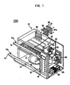
- a microwave oven 100 includes a cabinet 10.
- the cabinet 10 is partitioned into a microwave cooking cavity 11, a toasting cavity 12, and a machine room 13. Food is heated and cooked using microwaves in the microwave cooking cavity 11. Bread is toasted in the toasting cavity 12.
- Several electrical devices are installed in the machine room 13. In this case, the toasting cavity 12 is located above the microwave cooking cavity 11, and the machine room 13 is located at a side of the microwave cooking cavity 11 and the toasting cavity 12.
- the microwave cooking cavity 11 and the toasting cavity 12 are opened at the fronts thereof, thus allowing food to be put into or taken out from the microwave cooking cavity 11 or the toasting cavity 12.
- Doors 14 and 15 are mounted to the fronts of the microwave cooking cavity 11 and the toasting cavity 12, thus opening or closing the microwave cooking cavity 11 and the toasting cavity 12, respectively.
- a control panel 16 is mounted to the front of the machine room 13, and is provided with a display unit 17 which displays the operation of the microwave oven 100 and a plurality of control buttons 18 which controls several functions of the microwave oven 100.
- the doors 14 and 15, which open or close the microwave cooking cavity 11 and the toasting cavity 12, respectively, are hinged at their lower portions to the fronts of the microwave cooking cavity 11 and the toasting cavity 12 to be rotated forward and backward. Hooks 14a and 15a are located on upper portions of the doors 14 and 15, respectively.
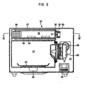
- a cooking tray 21 is mounted to a lower portion of the microwave cooking cavity 11 to be rotated to heat food placed on the cooking tray 21 uniformly.
- a drive motor 22 is installed in the space between the bottom of the microwave cooking cavity 11 and the cabinet's bottom under the microwave cooking cavity 11 to rotate the cooking tray 21.
- a magnetron 23, a high-voltage transformer 24, and a high-voltage condenser 25 are installed in the machine room 13. The magnetron 23 irradiates microwaves into the microwave cooking cavity 11. The high-voltage transformer 24 and the high-voltage condenser 25 function to apply a high voltage to the magnetron 23.
- a cooling fan 26 is mounted to a rear wall of the machine room 13, and functions to blow exterior air into the machine room 13 to cool the electrical devices installed in the machine room 13.
- Upper and lower heaters 27 and 28 are mounted to upper and lower portions of the toasting cavity 12, respectively, to heat and toast bread. When power is applied to the microwave oven 100, the upper and lower heaters 27 and 28 are heated.
- a grill member 29 made of a plurality of wires is provided above the lower heater 28 in the toasting cavity 12 so that bread placed on the grill member 29 is spaced apart from the lower heater 28.
- the toasting cavity 12 is provided with a ventilating unit to ventilate the toasting cavity 12.
- the ventilating unit includes a plurality of air inlet ports 31, a ventilating fan 32, and a plurality of air outlet ports 34.
- a sidewall 30 between the machine room 13 and the toasting cavity 12 is perforated in a predetermined area to form the air inlet ports 31.
- the ventilating fan 32 is mounted at the sidewall through which the air inlet ports 31 are formed, thus circulating air from the machine room 13 into the toasting cavity 12.
- a rear wall of the toasting cavity 12 is perforated in a predetermined area to form the air outlet ports 34, thus discharging air from the toasting cavity 12 to the outside of the microwave oven.
- a deodorizing filter 35 is provided at the rear wall through which the air outlet ports 34 are formed.
- An annular air guide member 33 is located on the sidewall 30 through which the air inlet ports 31 are formed, and guides air so that it flows into the toasting cavity 12 through the air inlet ports 31 by operation of the ventilating fan 32. Further, a depressed seat 36 is located on the rear wall of the toasting cavity 12, so that the deodorizing filter 35 is seated into the depressed seat 36. A cover member 37 is fastened to the depressed seat 36 using setscrews 38 to cover the deodorizing filter 35. A plurality of perforations 37a are located in the cover member 37.
- microwave oven 100 The operation and use of the microwave oven 100 according to the present invention is described below.
- the food is laid in the microwave cooking cavity 11. Next, with the operation of the microwave oven 100, microwaves generated from the magnetron 23 are irradiated into the microwave cooking cavity 11, thus cooking the food.
- the control panel 16 is manipulated to heat the upper and lower heaters 27 and 28, thus toasting the bread.
- smoke and odors generated in the toasting cavity 12 are discharged to the outside of the microwave oven 100 by the operation of the ventilating fan 32. That is, when the ventilating fan 32 is operated, air flows from the machine room 13 through the air inlet ports 31 into the toasting cavity 12. Air in the toasting cavity 12 is discharged to the outside through the air outlet ports 34.
- the present invention provides a microwave oven, which has a toasting cavity in addition to a microwave cooking cavity, thus allowing food to be cooked using microwaves and making well-toasted breads.
Landscapes
- Engineering & Computer Science (AREA)
- Physics & Mathematics (AREA)
- Electromagnetism (AREA)
- Food Science & Technology (AREA)
- Chemical & Material Sciences (AREA)
- Combustion & Propulsion (AREA)
- Mechanical Engineering (AREA)
- General Engineering & Computer Science (AREA)
- Electric Ovens (AREA)
- Electric Stoves And Ranges (AREA)
Claims (16)
- Mikrowellenofen, umfassend:ein Gehäuse (10), das in einen Mikrowellenkochhohlraum (11), einen Toasthohlraum (12) und einen Maschinenraum (13) partitioniert ist;eine in dem Maschinenraum (13) installierte Mikrowellengenerierungseinheit (23) zum Generieren von Mikrowellen in den Mikrowellenkochhohlraum (11);eine in dem Toasthohlraum (12) installierte Heizeinheit (27, 28) zum Heizen des Toasthohlraums (12) undeine Ventiliereinheit (31, 32, 34), die einen Lufteinlaßport (31), einen Ventilator (32) und einen Luftauslaßport (34) umfaßt;
dadurch gekennzeichnet, daßdie Ventiliereinheit (31, 32, 34) zum Ventilieren des Toasthohlraums (12) positioniert ist;der Lufteinlaßport (31) an einem vorbestimmten Ort an einer Seitenwand zwischen dem Maschinenraum (13) und dem Toasthohlraum (12) vorgesehen ist;der Ventilator (32) an dem Ort an der Seitenwand, durch die der Lufteinlaßport (31) ausgebildet ist, montiert ist, wodurch Luft von dem Maschinenraum (13) in den Toasthohlraum (12) umgewälzt wird; undsich der Luftauslaßport (34) an einem vorbestimmten Ort an einer Wand des Toasthohlraums (12) befindet, um Luft aus dem Toasthohlraum (12) nach außen auszutragen. - Mikrowellenofen nach Anspruch 1, wobei sich der Toasthohlraum (12) über dem Mikrowellenkochhohlraum (11) befindet und sich der Maschinenraum (13) an einer Seite des Toasthohlraums (12) und des Mikrowellenkochhohlraums (11) befindet.
- Mikrowellenofen nach Anspruch 1 oder 2, wobei die Heizeinheit (27, 28) eine an einer oberen Position in dem Toasthohlraum (12) installierte obere Heizung (27) und eine an einer unteren Position in dem Toasthohlraum (12) installierte untere Heizung (28) umfaßt und
sich ein Grillglied (29) über der unteren Heizung (28) befindet und dafür ausgelegt ist, daß Brot darauf plaziert wird. - Mikrowellenofen nach einem vorhergehenden Anspruch, weiterhin umfassend einen desodorierenden Filter (35) an dem Abschnitt der Wand, durch den der Luftauslaßport (34) ausgebildet ist, wodurch Gerüche aus der Luft entfernt werden, die aus dem Toasthohlraum (12) aus dem Mikrowellenofen nach außen ausgetragen wird.
- Mikrowellenofen nach einem vorhergehenden Anspruch, weiterhin umfassend ein ringförmiges Luftleitglied (33) an der Seitenwand, durch die der Lufteinlaßport (31) ausgebildet ist, das Luft in den Toasthohlraum (12) leitet.
- Mikrowellenofen nach einem vorhergehenden Anspruch, weiterhin umfassend einen vertieften Sitz (36) an einer Rückwand des Toasthohlraums (12).
- Mikrowellenofen nach Anspruch 6, weiterhin enthaltend einen in den vertieften Sitz (36) eingesetzten desodorierenden Filter (35).
- Mikrowellenofen nach Anspruch 7, wobei ein perforiertes Abdeckglied an dem vertieften Sitz (36) befestigt ist, um den desodorierenden Filter (35) zu bedecken.
- Mikrowellenofen nach einem vorhergehenden Anspruch, wobei der Toasthohlraum (12) und der Mikrowellenkochhohlraum (11) an Fronten davon geöffnet sind und Türen (14, 15) an den offenen Fronten des Toasthohlraums (12) und des Mikrowellenkochhohlraums (11) montiert sind, um den Toasthohlraum (12) bzw. den Mikrowellenkochhohlraum (11) zu öffnen oder zu schließen.
- Mikrowellenofen nach Anspruch 9, wobei die Türen (14, 15) nach vorne und hinten gedreht werden, um den Toasthohlraum (12) bzw. den Mikrowellenkochhohlraum (11) zu öffnen oder zu schließen.
- Mikrowellenofen nach einem vorhergehenden Anspruch, wobei ein Hochspannungstransformator (24) und ein Hochspannungskondensator (25), in dem Maschinenraum (13) installiert, eine Hochspannung an die Mikrowellengenerierungseinheit (23) anlegen, und ein in dem Maschinenraum (13) installiertes Kühlgebläse (26) den Hochspannungstransformator (24) und den Hochspannungskondensator (25) kühlt.
- Verfahren zum Kombinieren von Toasten und Mikrowellenkochen in einem Mikrowellenofen, umfassend:Partitionieren eines Gehäuses (10) in einen Mikrowellenkochhohlraum (11), einen Toasthohlraum (12) und einen Maschinenraum (13) undGenerieren von Mikrowellen in den Mikrowellenkochhohlraum (11) und Erhitzen des Toasthohlraums (12) mit einer Heizeinheit (27, 28),
gekennzeichnet durchBelüften des Toasthohlraums (12) unter Verwendung einer Ventilierungseinheit (31, 32, 34) durch:Verwenden eines Lufteinlaßports (31) an einer vorbestimmten Stelle an einer Seitenwand zwischen dem Maschinenraum (13) und dem Toasthohlraum (12), um Zugang zu Luft außerhalb des Mikrowellenofens bereitzustellen;Verwenden eines Ventilators (32), der an der Seitenwand montiert ist, durch die der Lufteinlaßport (31) ausgebildet ist, um Luft von dem Maschinenraum (13) in den Toasthohlraum (12) umzuwälzen; undVerwenden eines Luftauslaßports (34) an einem vorbestimmten Ort an der Wand des Toasthohlraums (12), um Luft aus dem Toasthohlraum (12) aus dem Mikrowellenofen nach außen auszutragen. - Verfahren nach Anspruch 12, wobei das Partitionieren das Unterteilen des Gehäuses (10) umfaßt, so daß sich der Toasthohlraum (12) über dem Mikrowellenkochhohlraum (11) befindet und sich der Maschinenraum (13) auf einer Seite des Toasthohlraums (12) und des Mikrowellenkochhohlraums (11) befindet.
- Verfahren nach Anspruch 12 oder 13, wobei das Partitionieren weiterhin das Unterteilen des Toasthohlraums (12) in einen oberen Abschnitt mit einer oberen Heizung (27) in dem Toasthohlraum (12), einen unteren Abschnitt mit einer unteren Heizung (28) und ein Grillglied (29) über der unteren Heizung (28) umfaßt, so daß das Grillglied (29) dafür ausgelegt ist, zu toastendes Lebensmittel/Brot zu tragen.
- Verfahren nach Anspruch 12, 13 oder 14, weiterhin umfassend das Verwenden eines desodorierenden Filters (35) an dem Abschnitt der Wand, durch den der Luftauslaßport (34) ausgebildet ist, um Gerüche aus der Luft zu entfernen, die von dem Toasthohlraum (12) aus dem Mikrowellenofen nach außen ausgetragen wird.
- Verfahren nach einem der Ansprüche 12 bis 15, wobei das Generieren von Mikrowellen in den Mikrowellenkochhohlraum (11) und das Heizen des Toasthohlraums (12) mit einer Heizeinheit (27, 28) beim Belüften des Toasthohlraums (12) unter Verwendung einer Ventiliereinheit (31, 32, 34) in einer Reihenfolge ausgeführt werden, die eine der folgenden umfaßt:simultan, in Reihenfolge und in umgekehrter Reihenfolge.
Applications Claiming Priority (2)
| Application Number | Priority Date | Filing Date | Title |
|---|---|---|---|
| KR2003005182 | 2003-01-27 | ||
| KR1020030005182A KR20040068681A (ko) | 2003-01-27 | 2003-01-27 | 전자렌지 |
Publications (3)
| Publication Number | Publication Date |
|---|---|
| EP1441569A2 EP1441569A2 (de) | 2004-07-28 |
| EP1441569A3 EP1441569A3 (de) | 2007-07-18 |
| EP1441569B1 true EP1441569B1 (de) | 2009-07-29 |
Family
ID=32589008
Family Applications (1)
| Application Number | Title | Priority Date | Filing Date |
|---|---|---|---|
| EP03253771A Expired - Lifetime EP1441569B1 (de) | 2003-01-27 | 2003-06-13 | Mikrowellenherd |
Country Status (6)
| Country | Link |
|---|---|
| US (1) | US7041949B2 (de) |
| EP (1) | EP1441569B1 (de) |
| JP (1) | JP4021831B2 (de) |
| KR (1) | KR20040068681A (de) |
| CN (1) | CN1274996C (de) |
| DE (1) | DE60328580D1 (de) |
Families Citing this family (22)
| Publication number | Priority date | Publication date | Assignee | Title |
|---|---|---|---|---|
| KR20050061702A (ko) * | 2003-12-18 | 2005-06-23 | 주식회사 대우일렉트로닉스 | 피자오븐 겸용 전자렌지의 오븐도어 냉각구조물 |
| US20050133499A1 (en) * | 2003-12-18 | 2005-06-23 | Daewoo Electronics Corporation | Microwave oven provided with a separate heater cooking chamber |
| KR20050078553A (ko) * | 2004-02-02 | 2005-08-05 | 삼성전자주식회사 | 가열조리기 |
| KR101412149B1 (ko) * | 2007-10-29 | 2014-07-02 | 엘지전자 주식회사 | 조리 기기 |
| KR101537407B1 (ko) * | 2007-11-15 | 2015-07-16 | 엘지전자 주식회사 | 조리기기 |
| KR101461380B1 (ko) * | 2008-04-15 | 2014-11-13 | 동부대우전자 주식회사 | 다기능 전자레인지 및 그 제어방법 |
| JP2010181112A (ja) * | 2009-02-06 | 2010-08-19 | Sharp Corp | 引出し型加熱調理器 |
| US8375849B2 (en) | 2009-09-01 | 2013-02-19 | Manitowoc Foodservice Companies, Llc | Method and apparatus for an air inlet in a cooking device |
| CN203314797U (zh) * | 2013-05-02 | 2013-12-04 | 张毅蔚 | 一种加热器具 |
| GB2515075B (en) * | 2013-06-13 | 2018-07-11 | Kenwood Ltd | Improved electric toaster |
| US10383182B2 (en) * | 2013-12-05 | 2019-08-13 | R-Menu Oy | Oven for heating and frying food |
| US20150359046A1 (en) * | 2014-06-05 | 2015-12-10 | Younes Mohseni | "2-IN-1 Toaster Oven" / "2-IN-1 Microwave Oven" |
| DE202014005299U1 (de) | 2014-07-01 | 2015-10-09 | Emilio Reales Bertomeo | Vorrichtung zum Erhitzen und/oder Garen von Fleischerzeugnissen |
| CN105030082B (zh) * | 2015-08-26 | 2017-12-15 | 广东新宝电器股份有限公司 | 全自动面包机 |
| US11079118B2 (en) | 2016-04-12 | 2021-08-03 | Whirlpool Corporation | Combination microwave and hood system |
| US11523473B2 (en) * | 2016-04-12 | 2022-12-06 | Whirlpool Corporation | Combination microwave and hood system |
| CN106852653A (zh) * | 2017-03-03 | 2017-06-16 | 华帝股份有限公司 | 一种烹饪加热器具及其去除异味的方法 |
| US11109712B2 (en) | 2018-12-10 | 2021-09-07 | Midea Group Co., Ltd. | Microwave oven with toaster |
| CN109991907B (zh) * | 2019-04-30 | 2021-07-20 | 广东美的厨房电器制造有限公司 | 烤箱及其控制系统和方法 |
| DE102019210149B4 (de) * | 2019-07-10 | 2022-09-01 | BSH Hausgeräte GmbH | Brotröster, Verschluss für einen Brotröster sowie Verfahren zum Rösten von Röstgut |
| CN112762486A (zh) * | 2021-02-03 | 2021-05-07 | 潮州市烯陶新材料有限公司 | 石墨烯远红外加热电炉 |
| CN114869130B (zh) * | 2022-05-05 | 2024-09-13 | 广东美的厨房电器制造有限公司 | 烹饪器具 |
Family Cites Families (12)
| Publication number | Priority date | Publication date | Assignee | Title |
|---|---|---|---|---|
| JPS55110835A (en) * | 1979-02-19 | 1980-08-26 | Matsushita Electric Ind Co Ltd | Cooking device |
| JPS62297634A (ja) * | 1986-06-17 | 1987-12-24 | Matsushita Electric Ind Co Ltd | 加熱調理器 |
| JPS6438524A (en) * | 1987-07-31 | 1989-02-08 | Matsushita Electric Ind Co Ltd | Microwave oven having electric oven |
| JPH01305231A (ja) * | 1988-06-01 | 1989-12-08 | Mitsubishi Electric Corp | 加熱調理器 |
| JPH061124B2 (ja) * | 1988-06-22 | 1994-01-05 | 三菱電機株式会社 | 食品加熱装置 |
| JP2905897B2 (ja) * | 1990-03-20 | 1999-06-14 | 三菱電機ホーム機器株式会社 | 電子レンジ |
| JPH04148115A (ja) * | 1990-10-08 | 1992-05-21 | Sharp Corp | 高周波加熱装置 |
| KR100301904B1 (ko) * | 1997-11-15 | 2001-11-22 | 구자홍 | 할로겐램프를구비한전자레인지의냉각장치 |
| US5990467A (en) * | 1998-05-13 | 1999-11-23 | Samsung Electronics Co., Ltd. | Microwave oven having improved structure for fixing a blower |
| JP2002235924A (ja) * | 2000-12-08 | 2002-08-23 | Lg Electronics Inc | トースターを具備した電子レンジ |
| KR100402609B1 (ko) * | 2001-09-11 | 2003-10-17 | 주식회사 엘지이아이 | 전자레인지의 토스터부 방열장치 |
| KR20040024394A (ko) * | 2002-09-14 | 2004-03-20 | 삼성전자주식회사 | 토스터를 갖춘 전자렌지 |
-
2003
- 2003-01-27 KR KR1020030005182A patent/KR20040068681A/ko not_active Application Discontinuation
- 2003-05-29 CN CNB031382347A patent/CN1274996C/zh not_active Expired - Fee Related
- 2003-06-13 EP EP03253771A patent/EP1441569B1/de not_active Expired - Lifetime
- 2003-06-13 DE DE60328580T patent/DE60328580D1/de not_active Expired - Lifetime
- 2003-09-29 US US10/671,602 patent/US7041949B2/en not_active Expired - Fee Related
- 2003-10-17 JP JP2003358411A patent/JP4021831B2/ja not_active Expired - Fee Related
Also Published As
| Publication number | Publication date |
|---|---|
| KR20040068681A (ko) | 2004-08-02 |
| JP4021831B2 (ja) | 2007-12-12 |
| US20040144774A1 (en) | 2004-07-29 |
| DE60328580D1 (de) | 2009-09-10 |
| CN1274996C (zh) | 2006-09-13 |
| EP1441569A3 (de) | 2007-07-18 |
| EP1441569A2 (de) | 2004-07-28 |
| JP2004226058A (ja) | 2004-08-12 |
| CN1517593A (zh) | 2004-08-04 |
| US7041949B2 (en) | 2006-05-09 |
Similar Documents
| Publication | Publication Date | Title |
|---|---|---|
| EP1441569B1 (de) | Mikrowellenherd | |
| KR100793797B1 (ko) | 히팅장치 및 이를 포함하는 조리기기 | |
| KR100705147B1 (ko) | 가열 조리기 | |
| CA2424326C (en) | Cooking appliance venting system | |
| EP1674796A2 (de) | Elektrischer Ofen | |
| US6809297B2 (en) | Combination rotisserie and convection oven having movable heating element | |
| NZ586502A (en) | Oven, typically microwave type, with door rotation causing cam to move plunger and sequentially actuate two switches | |
| CN221083455U (zh) | 双区域多功能烹饪器具 | |
| US6894257B2 (en) | Microwave oven | |
| US11457768B1 (en) | Indoor smokeless grill and air fryer combination device | |
| US20040050841A1 (en) | Microwave oven with toaster | |
| US6953920B2 (en) | Combination microwave oven and steamer | |
| EP1392084B1 (de) | Kochvorrichtung versehen mit Heizelementen | |
| JPH024131A (ja) | 食品加熱装置 | |
| WO2022265786A1 (en) | Multifunction toaster oven | |
| CN216293794U (zh) | 台面烹饪系统 | |
| KR100700771B1 (ko) | 슬라이딩 타입의 백가드가 구비된 오븐레인지 | |
| KR100674570B1 (ko) | 컨백션전자레인지의 습기제거방법 | |
| KR100984216B1 (ko) | 오븐 및 오븐의 제어방법 | |
| JP2022132884A (ja) | 加熱調理器 | |
| KR20030080929A (ko) | 계란구이장치가 구비된 전자레인지 | |
| WO2022265785A1 (en) | Multifunction toaster oven | |
| KR20050078553A (ko) | 가열조리기 | |
| JPH05288351A (ja) | 電子レンジ | |
| KR19980011477U (ko) | 구이 겸용 전자렌지 |
Legal Events
| Date | Code | Title | Description |
|---|---|---|---|
| PUAI | Public reference made under article 153(3) epc to a published international application that has entered the european phase |
Free format text: ORIGINAL CODE: 0009012 |
|
| 17P | Request for examination filed |
Effective date: 20030701 |
|
| AK | Designated contracting states |
Kind code of ref document: A2 Designated state(s): AT BE BG CH CY CZ DE DK EE ES FI FR GB GR HU IE IT LI LU MC NL PT RO SE SI SK TR |
|
| AX | Request for extension of the european patent |
Extension state: AL LT LV MK |
|
| PUAL | Search report despatched |
Free format text: ORIGINAL CODE: 0009013 |
|
| AK | Designated contracting states |
Kind code of ref document: A3 Designated state(s): AT BE BG CH CY CZ DE DK EE ES FI FR GB GR HU IE IT LI LU MC NL PT RO SE SI SK TR |
|
| AX | Request for extension of the european patent |
Extension state: AL LT LV MK |
|
| 17Q | First examination report despatched |
Effective date: 20070921 |
|
| AKX | Designation fees paid |
Designated state(s): DE FR GB |
|
| GRAP | Despatch of communication of intention to grant a patent |
Free format text: ORIGINAL CODE: EPIDOSNIGR1 |
|
| GRAS | Grant fee paid |
Free format text: ORIGINAL CODE: EPIDOSNIGR3 |
|
| GRAA | (expected) grant |
Free format text: ORIGINAL CODE: 0009210 |
|
| AK | Designated contracting states |
Kind code of ref document: B1 Designated state(s): DE FR GB |
|
| REG | Reference to a national code |
Ref country code: GB Ref legal event code: FG4D |
|
| REF | Corresponds to: |
Ref document number: 60328580 Country of ref document: DE Date of ref document: 20090910 Kind code of ref document: P |
|
| PLBE | No opposition filed within time limit |
Free format text: ORIGINAL CODE: 0009261 |
|
| STAA | Information on the status of an ep patent application or granted ep patent |
Free format text: STATUS: NO OPPOSITION FILED WITHIN TIME LIMIT |
|
| 26N | No opposition filed |
Effective date: 20100503 |
|
| REG | Reference to a national code |
Ref country code: FR Ref legal event code: PLFP Year of fee payment: 13 |
|
| PGFP | Annual fee paid to national office [announced via postgrant information from national office to epo] |
Ref country code: DE Payment date: 20150521 Year of fee payment: 13 Ref country code: GB Payment date: 20150522 Year of fee payment: 13 |
|
| PGFP | Annual fee paid to national office [announced via postgrant information from national office to epo] |
Ref country code: FR Payment date: 20150521 Year of fee payment: 13 |
|
| REG | Reference to a national code |
Ref country code: DE Ref legal event code: R119 Ref document number: 60328580 Country of ref document: DE |
|
| GBPC | Gb: european patent ceased through non-payment of renewal fee |
Effective date: 20160613 |
|
| REG | Reference to a national code |
Ref country code: FR Ref legal event code: ST Effective date: 20170228 |
|
| PG25 | Lapsed in a contracting state [announced via postgrant information from national office to epo] |
Ref country code: FR Free format text: LAPSE BECAUSE OF NON-PAYMENT OF DUE FEES Effective date: 20160630 Ref country code: DE Free format text: LAPSE BECAUSE OF NON-PAYMENT OF DUE FEES Effective date: 20170103 |
|
| PG25 | Lapsed in a contracting state [announced via postgrant information from national office to epo] |
Ref country code: GB Free format text: LAPSE BECAUSE OF NON-PAYMENT OF DUE FEES Effective date: 20160613 |