EP1439976B1 - Geschwindigkeitsregelung für fahrzeug - Google Patents
Geschwindigkeitsregelung für fahrzeug Download PDFInfo
- Publication number
- EP1439976B1 EP1439976B1 EP02803141A EP02803141A EP1439976B1 EP 1439976 B1 EP1439976 B1 EP 1439976B1 EP 02803141 A EP02803141 A EP 02803141A EP 02803141 A EP02803141 A EP 02803141A EP 1439976 B1 EP1439976 B1 EP 1439976B1
- Authority
- EP
- European Patent Office
- Prior art keywords
- vehicle
- speed
- throttle opening
- disposed
- target speed
- Prior art date
- Legal status (The legal status is an assumption and is not a legal conclusion. Google has not performed a legal analysis and makes no representation as to the accuracy of the status listed.)
- Expired - Lifetime
Links
Images


Classifications
-
- B—PERFORMING OPERATIONS; TRANSPORTING
- B60—VEHICLES IN GENERAL
- B60K—ARRANGEMENT OR MOUNTING OF PROPULSION UNITS OR OF TRANSMISSIONS IN VEHICLES; ARRANGEMENT OR MOUNTING OF PLURAL DIVERSE PRIME-MOVERS IN VEHICLES; AUXILIARY DRIVES FOR VEHICLES; INSTRUMENTATION OR DASHBOARDS FOR VEHICLES; ARRANGEMENTS IN CONNECTION WITH COOLING, AIR INTAKE, GAS EXHAUST OR FUEL SUPPLY OF PROPULSION UNITS IN VEHICLES
- B60K31/00—Vehicle fittings, acting on a single sub-unit only, for automatically controlling vehicle speed, i.e. preventing speed from exceeding an arbitrarily established velocity or maintaining speed at a particular velocity, as selected by the vehicle operator
- B60K31/02—Vehicle fittings, acting on a single sub-unit only, for automatically controlling vehicle speed, i.e. preventing speed from exceeding an arbitrarily established velocity or maintaining speed at a particular velocity, as selected by the vehicle operator including electrically actuated servomechanism including an electric control system or a servomechanism in which the vehicle velocity affecting element is actuated electrically
- B60K31/04—Vehicle fittings, acting on a single sub-unit only, for automatically controlling vehicle speed, i.e. preventing speed from exceeding an arbitrarily established velocity or maintaining speed at a particular velocity, as selected by the vehicle operator including electrically actuated servomechanism including an electric control system or a servomechanism in which the vehicle velocity affecting element is actuated electrically and means for comparing one electrical quantity, e.g. voltage, pulse, waveform, flux, or the like, with another quantity of a like kind, which comparison means is involved in the development of an electrical signal which is fed into the controlling means
- B60K31/042—Vehicle fittings, acting on a single sub-unit only, for automatically controlling vehicle speed, i.e. preventing speed from exceeding an arbitrarily established velocity or maintaining speed at a particular velocity, as selected by the vehicle operator including electrically actuated servomechanism including an electric control system or a servomechanism in which the vehicle velocity affecting element is actuated electrically and means for comparing one electrical quantity, e.g. voltage, pulse, waveform, flux, or the like, with another quantity of a like kind, which comparison means is involved in the development of an electrical signal which is fed into the controlling means where at least one electrical quantity is set by the vehicle operator
- B60K31/045—Vehicle fittings, acting on a single sub-unit only, for automatically controlling vehicle speed, i.e. preventing speed from exceeding an arbitrarily established velocity or maintaining speed at a particular velocity, as selected by the vehicle operator including electrically actuated servomechanism including an electric control system or a servomechanism in which the vehicle velocity affecting element is actuated electrically and means for comparing one electrical quantity, e.g. voltage, pulse, waveform, flux, or the like, with another quantity of a like kind, which comparison means is involved in the development of an electrical signal which is fed into the controlling means where at least one electrical quantity is set by the vehicle operator in a memory, e.g. a capacitor
- B60K31/047—Vehicle fittings, acting on a single sub-unit only, for automatically controlling vehicle speed, i.e. preventing speed from exceeding an arbitrarily established velocity or maintaining speed at a particular velocity, as selected by the vehicle operator including electrically actuated servomechanism including an electric control system or a servomechanism in which the vehicle velocity affecting element is actuated electrically and means for comparing one electrical quantity, e.g. voltage, pulse, waveform, flux, or the like, with another quantity of a like kind, which comparison means is involved in the development of an electrical signal which is fed into the controlling means where at least one electrical quantity is set by the vehicle operator in a memory, e.g. a capacitor the memory being digital
-
- B—PERFORMING OPERATIONS; TRANSPORTING
- B60—VEHICLES IN GENERAL
- B60W—CONJOINT CONTROL OF VEHICLE SUB-UNITS OF DIFFERENT TYPE OR DIFFERENT FUNCTION; CONTROL SYSTEMS SPECIALLY ADAPTED FOR HYBRID VEHICLES; ROAD VEHICLE DRIVE CONTROL SYSTEMS FOR PURPOSES NOT RELATED TO THE CONTROL OF A PARTICULAR SUB-UNIT
- B60W2530/00—Input parameters relating to vehicle conditions or values, not covered by groups B60W2510/00 or B60W2520/00
- B60W2530/16—Driving resistance
-
- B—PERFORMING OPERATIONS; TRANSPORTING
- B60—VEHICLES IN GENERAL
- B60W—CONJOINT CONTROL OF VEHICLE SUB-UNITS OF DIFFERENT TYPE OR DIFFERENT FUNCTION; CONTROL SYSTEMS SPECIALLY ADAPTED FOR HYBRID VEHICLES; ROAD VEHICLE DRIVE CONTROL SYSTEMS FOR PURPOSES NOT RELATED TO THE CONTROL OF A PARTICULAR SUB-UNIT
- B60W2552/00—Input parameters relating to infrastructure
- B60W2552/15—Road slope
-
- B—PERFORMING OPERATIONS; TRANSPORTING
- B60—VEHICLES IN GENERAL
- B60W—CONJOINT CONTROL OF VEHICLE SUB-UNITS OF DIFFERENT TYPE OR DIFFERENT FUNCTION; CONTROL SYSTEMS SPECIALLY ADAPTED FOR HYBRID VEHICLES; ROAD VEHICLE DRIVE CONTROL SYSTEMS FOR PURPOSES NOT RELATED TO THE CONTROL OF A PARTICULAR SUB-UNIT
- B60W2556/00—Input parameters relating to data
- B60W2556/45—External transmission of data to or from the vehicle
- B60W2556/50—External transmission of data to or from the vehicle for navigation systems
-
- B—PERFORMING OPERATIONS; TRANSPORTING
- B60—VEHICLES IN GENERAL
- B60W—CONJOINT CONTROL OF VEHICLE SUB-UNITS OF DIFFERENT TYPE OR DIFFERENT FUNCTION; CONTROL SYSTEMS SPECIALLY ADAPTED FOR HYBRID VEHICLES; ROAD VEHICLE DRIVE CONTROL SYSTEMS FOR PURPOSES NOT RELATED TO THE CONTROL OF A PARTICULAR SUB-UNIT
- B60W2710/00—Output or target parameters relating to a particular sub-units
- B60W2710/06—Combustion engines, Gas turbines
- B60W2710/0605—Throttle position
-
- F—MECHANICAL ENGINEERING; LIGHTING; HEATING; WEAPONS; BLASTING
- F02—COMBUSTION ENGINES; HOT-GAS OR COMBUSTION-PRODUCT ENGINE PLANTS
- F02D—CONTROLLING COMBUSTION ENGINES
- F02D2200/00—Input parameters for engine control
- F02D2200/70—Input parameters for engine control said parameters being related to the vehicle exterior
- F02D2200/701—Information about vehicle position, e.g. from navigation system or GPS signal
-
- F—MECHANICAL ENGINEERING; LIGHTING; HEATING; WEAPONS; BLASTING
- F02—COMBUSTION ENGINES; HOT-GAS OR COMBUSTION-PRODUCT ENGINE PLANTS
- F02D—CONTROLLING COMBUSTION ENGINES
- F02D41/00—Electrical control of supply of combustible mixture or its constituents
- F02D41/02—Circuit arrangements for generating control signals
- F02D41/021—Introducing corrections for particular conditions exterior to the engine
-
- F—MECHANICAL ENGINEERING; LIGHTING; HEATING; WEAPONS; BLASTING
- F16—ENGINEERING ELEMENTS AND UNITS; GENERAL MEASURES FOR PRODUCING AND MAINTAINING EFFECTIVE FUNCTIONING OF MACHINES OR INSTALLATIONS; THERMAL INSULATION IN GENERAL
- F16H—GEARING
- F16H59/00—Control inputs to control units of change-speed-, or reversing-gearings for conveying rotary motion
- F16H59/60—Inputs being a function of ambient conditions
- F16H59/66—Road conditions, e.g. slope, slippery
- F16H2059/663—Road slope
-
- F—MECHANICAL ENGINEERING; LIGHTING; HEATING; WEAPONS; BLASTING
- F16—ENGINEERING ELEMENTS AND UNITS; GENERAL MEASURES FOR PRODUCING AND MAINTAINING EFFECTIVE FUNCTIONING OF MACHINES OR INSTALLATIONS; THERMAL INSULATION IN GENERAL
- F16H—GEARING
- F16H59/00—Control inputs to control units of change-speed-, or reversing-gearings for conveying rotary motion
- F16H59/60—Inputs being a function of ambient conditions
- F16H59/66—Road conditions, e.g. slope, slippery
- F16H2059/666—Determining road conditions by using vehicle location or position, e.g. from global navigation systems [GPS]
-
- F—MECHANICAL ENGINEERING; LIGHTING; HEATING; WEAPONS; BLASTING
- F16—ENGINEERING ELEMENTS AND UNITS; GENERAL MEASURES FOR PRODUCING AND MAINTAINING EFFECTIVE FUNCTIONING OF MACHINES OR INSTALLATIONS; THERMAL INSULATION IN GENERAL
- F16H—GEARING
- F16H61/00—Control functions within control units of change-speed- or reversing-gearings for conveying rotary motion ; Control of exclusively fluid gearing, friction gearing, gearings with endless flexible members or other particular types of gearing
- F16H2061/0015—Transmission control for optimising fuel consumptions
-
- F—MECHANICAL ENGINEERING; LIGHTING; HEATING; WEAPONS; BLASTING
- F16—ENGINEERING ELEMENTS AND UNITS; GENERAL MEASURES FOR PRODUCING AND MAINTAINING EFFECTIVE FUNCTIONING OF MACHINES OR INSTALLATIONS; THERMAL INSULATION IN GENERAL
- F16H—GEARING
- F16H59/00—Control inputs to control units of change-speed-, or reversing-gearings for conveying rotary motion
- F16H59/60—Inputs being a function of ambient conditions
- F16H59/66—Road conditions, e.g. slope, slippery
-
- F—MECHANICAL ENGINEERING; LIGHTING; HEATING; WEAPONS; BLASTING
- F16—ENGINEERING ELEMENTS AND UNITS; GENERAL MEASURES FOR PRODUCING AND MAINTAINING EFFECTIVE FUNCTIONING OF MACHINES OR INSTALLATIONS; THERMAL INSULATION IN GENERAL
- F16H—GEARING
- F16H61/00—Control functions within control units of change-speed- or reversing-gearings for conveying rotary motion ; Control of exclusively fluid gearing, friction gearing, gearings with endless flexible members or other particular types of gearing
- F16H61/02—Control functions within control units of change-speed- or reversing-gearings for conveying rotary motion ; Control of exclusively fluid gearing, friction gearing, gearings with endless flexible members or other particular types of gearing characterised by the signals used
- F16H61/0202—Control functions within control units of change-speed- or reversing-gearings for conveying rotary motion ; Control of exclusively fluid gearing, friction gearing, gearings with endless flexible members or other particular types of gearing characterised by the signals used the signals being electric
- F16H61/0204—Control functions within control units of change-speed- or reversing-gearings for conveying rotary motion ; Control of exclusively fluid gearing, friction gearing, gearings with endless flexible members or other particular types of gearing characterised by the signals used the signals being electric for gearshift control, e.g. control functions for performing shifting or generation of shift signal
- F16H61/0213—Control functions within control units of change-speed- or reversing-gearings for conveying rotary motion ; Control of exclusively fluid gearing, friction gearing, gearings with endless flexible members or other particular types of gearing characterised by the signals used the signals being electric for gearshift control, e.g. control functions for performing shifting or generation of shift signal characterised by the method for generating shift signals
-
- F—MECHANICAL ENGINEERING; LIGHTING; HEATING; WEAPONS; BLASTING
- F16—ENGINEERING ELEMENTS AND UNITS; GENERAL MEASURES FOR PRODUCING AND MAINTAINING EFFECTIVE FUNCTIONING OF MACHINES OR INSTALLATIONS; THERMAL INSULATION IN GENERAL
- F16H—GEARING
- F16H61/00—Control functions within control units of change-speed- or reversing-gearings for conveying rotary motion ; Control of exclusively fluid gearing, friction gearing, gearings with endless flexible members or other particular types of gearing
- F16H61/70—Control functions within control units of change-speed- or reversing-gearings for conveying rotary motion ; Control of exclusively fluid gearing, friction gearing, gearings with endless flexible members or other particular types of gearing specially adapted for change-speed gearing in group arrangement, i.e. with separate change-speed gear trains arranged in series, e.g. range or overdrive-type gearing arrangements
Definitions
- the present invention relates to motor vehicle comprising an internal combustion engine and an electronic control unit for controlling the engine depending on the setting of a manual throttle, an electronic control unit for controlling the transmission, depending on a set position of a manual gear selector.
- Possible variants could be to use electronic maps together with a positioning system (e.g. a Global Positioning System, GPS) or extrapolate a future position for the vehicle.
- a positioning system e.g. a Global Positioning System, GPS
- One disadvantage of this system is that it does not take into consideration how the road varies in elevation between two points of measurement, and extreme points (e.g. the crest of a hill) between the two points of measurement are thus not taken into account in certain cases.
- the engine and the transmission are set in accordance with the known technology, on the basis of how great the difference in elevation is between the two points of measurement, and the instantaneous throttle position.
- Throttle position means in this case and in the following text both an adjustable cruise control and an accelerator pedal.
- US-A-5 832 400 only takes into consideration, as was mentioned, a single point of measurement during a certain time or distance into the future, in order to see if the instantaneous engine torque will be sufficient, or if the engine and/or transmission needs to be reset. It is also described how a plurality of points of measurement can be used but in that case a mean value thereof is used, thus providing one value for the required driving force. With a transmission which is shifted sequentially and with the method just described, there is an uncertainty in the system which results in tangible consequences in the form of less than satisfactory cruise control function, uneven acceleration and unnecessarily large exhaust emissions.
- the document EP 1 053 903 depicts a vehicular velocity controlling apparatus and methods to follow up a preceding vehicle which is running ahead of the vehicle with an appropriate inter-vehicle distance maintained.
- An inter-vehicle sensor which is constituted by a radar unit as an inter-vehicle distance detector which detects an inter-vehicle distance to the preceding vehicle is provided.
- a range measurement instrument to measure an inter-vehicle distance can be applied utilizing the radar to measure the inter-vehicle distance which sweeps, e.g. a laser beam in a front width-wise direction and receives a reflected laser beam from any object, e.g.
- the vehicle has a road surface gradient detector to detect a current descending slope on which the vehicle is running.
- the apparatus is arranged to control the speed of the vehicle taking in account the inter-vehicle distance from the vehicle to a preceding vehicle and present road slope.
- the document US-A-6 029 107 depicts a control apparatus of a conventional non-step type automatic transmission (CVT) for a vehicle.
- the apparatus allows to control the gear ratio automatically according to the condition of road surface so that effective engine brake suitable for a present road gradient can be automatically applied on the downhill and effective driving force suitable for the road gradient can be automatically obtained on the uphill.
- the apparatus is provided with a road gradient estimating part for estimating the gradient of road on which the vehicle is running, and a part for determining whether or not the estimate is beyond a predetermined threshold value, The controlling of the gear ratio is performed depending on if the gradient estimate is above the threshold value or not.
- cruise controls function by controlling a throttle opening or a braking process, which is described in US 5 894731, until a selected or given target speed is reached.
- the cruise control will attempt to brake the vehicle down to the target speed, regardless of the road incline after the end of the downhill stretch.
- the cruise control in this situation, will compensate by greatly increasing the throttle opening and shifting down.
- Another example of the same type of problem is the case of the extension of the problem just described, where the vehicle is moving uphill at lower than target speed and reaches the crest, whereupon the continued open throttle will result in excess speed in the subsequent downhill stretch, and the vehicle will be forced to brake to once again reach the target speed.
- the purpose of the present invention is to achieve a motor vehicle of the type described by way of introduction, which removes the above mentioned problems by providing a system and a method, which, with the aid of a cruise control function, controls throttle opening and braking, where the braking is effected using auxiliary brakes for example, to obtain lower vehicle fuel consumption. There are also achieved lower noise and exhaust emissions, more even acceleration and more comfortable cruising.
- the second control unit is disposed, under set preconditions, to perform computer simulations for a longer period forward (30 seconds or more), where the information on instantaneous position is obtained with the aid of GPS and/or where future positions are provided by information from an electronic map.
- estimates, (extrapolations) can be made concerning road incline and information can thus be obtained on the topology surrounding the vehicle and its future position.
- the present invention is preferably intended for, but is not limited to, automated manual transmissions.
- a significant difference in relation to the known technology (Automated Power Transmission) referred to, is that shifting in the present case takes place with force interruption.
- shifting up in an up-hill incline will be successful, even if the driving force were theoretically sufficient because if the shifting takes too long, the vehicle will be retarded too much.
- the second control unit is disposed, with the aid of electronics and sensors, to limit the throttle opening when there are large speed deviations and when the road is inclined downhill.
- the second control unit is disposed, with the aid of electronics and sensors, to keep the throttle open when the vehicle speed is greater than that set in the cruise control and the vehicle is approaching an uphill incline in which the reduction in speed would be so great that the maximum engine torque would not be able to accelerate the vehicle before the vehicle speed has dropped to the target speed.
- the second control unit is disposed, with the aid of electronics and data from sensors, to adjust the throttle opening when the vehicle is approaching the end of an uphill incline, and where the vehicle speed is less than the target speed, gradually adjusting to a future lesser throttle opening.
- the second control unit is disposed to adjust the throttle opening, when the vehicle approaches the beginning of a downhill incline, to gradually adjust to a future lesser throttle opening, i.e. the throttle opening which together with gravity and driving resistance will accelerate the vehicle to the target speed within a predetermined time period.
- the second control unit is disposed to adjust possibly applied auxiliary brakes and possibly the throttle opening, as the vehicle approaches the end of a downhill incline, to a future greater throttle opening required to maintain the target speed.
- the second control unit is disposed to adjust possibly applied auxiliary brakes and possibly the throttle opening, as the vehicle approaches the end of a downhill incline, so as to permit a temporary increase in speed, the maximum level of which is predetermined in the second control unit.
- the second control unit is disposed to release the auxiliary brakes, when the vehicle approaches an uphill incline and where the vehicle speed exceeds the target speed, to not brake off energy since the retardation of the vehicle in the uphill incline will adapt the vehicle speed to the target speed.
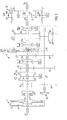
- Fig. 1 shows a schematic representation of one embodiment of a drive unit according to the invention
- Fig. 2 shows the clutch and the gearbox in Fig. 1 on a larger scale
- Fig. 3 shows an overview of inputs into the second control unit.
- Fig. 1, 1 designates a six-cylinder internal combustion engine, e.g. a diesel engine, the crankshaft 2 of which is coupled to a single-plate dry disk clutch which is designated generally by reference number 3 and is enclosed in a clutch case 4.
- a single-plate disk clutch a dual disk clutch can be used.
- the crankshaft 2 is connected non-rotatably to the clutch housing 5 of the clutch 3, while its disk plate 6 is connected non-rotatably to an input shaft 7, which is mounted rotatably in the casing 8 of a gearbox designated generally by reference number 9.
- a main shaft 10 and an intermediate shaft 11 are also mounted rotatably in the casing 8.
- first control unit 48 for controlling the engine
- second control unit 45 for controlling the transmission
- auxiliary brakes 60 are controlled from and second control unit via the first control unit 48.
- the auxiliary brakes can be for example compression brakes or exhaust brakes.
- the first and second control units (48 and 45, respectively) are adapted for communication with each other.
- a gear wheel 12 is mounted rotatably on the input shaft 7 and is lockable on the shaft by means of an engaging sleeve 13 which is provided with synchronizing means and is mounted non-rotatably but axially displaceably on a hub 14 connected non-rotatably to the input shaft 7.
- an engaging sleeve 13 which is provided with synchronizing means and is mounted non-rotatably but axially displaceably on a hub 14 connected non-rotatably to the input shaft 7.
- a gear wheel 15 mounted rotatably on the main shaft 10 is also lockable relative to the input shaft 7.
- the gear wheels 12 and 15 engage with gear wheels 16 and 17, respectively, which are connected non-rotatably to the intermediate shaft 11.
- gear wheels 18, 19 and 20 Arranged in a rotationally fixed manner on the intermediate shaft 11 are further gear wheels 18, 19 and 20 which engage with gear wheels 21, 22 and 23, respectively, which are mounted rotatably on the main shaft 10 and are lockable on the main shaft by means of engaging sleeves 24 and 25, respectively, which, in the illustrative embodiment shown, do not have synchronizing arrangements.
- a further gear wheel 28 is mounted rotatably on the main shaft 10 and engages with an intermediate gear wheel 30, which is mounted rotatably on a separate shaft 29 and engages in turn the intermediate shaft gear wheel 20.
- the gear wheel 28 is lockable on its shaft by means of an engaging sleeve 26.
- the gear wheel pairs 12, 16 and 15, 17 and also the engaging sleeve 13 form a split gearing with a low gear stage LS and a high gear stage HS.
- the gear wheel pair 15, 17 also forms, together with the gear wheel pairs 21, 18, 22, 19, 23, 20 and 28, 30, a basic gearbox with four forward gears and one reverse gear.
- a gear wheel 31 Arranged in a rotationally fixed manner on the output end of the main shaft is a gear wheel 31 which forms the sun gear in a two-stage range gear of the planetary type designated by reference number 32, the planet wheel carrier 33 of which is connected in a rotationally fixed manner to a shaft 34 which forms the output shaft of the gearbox.
- the planet wheels 35 of the range gear 32 engage with a ring gear 36, which, by means of an engaging sleeve 37, is lockable relative to the gearbox casing 8 for low range LR and relative to the planet wheel carrier 33 for high range HR.
- the engaging sleeve also has a neutral position NR between the gear positions LR and HR. In the neutral position NR the output shaft 34 is released from the main shaft 10.
- the engaging sleeves 13, 24, 25, 26 and 37 are displaceable as shown by the arrows in Fig. 2, to provide the gear stages shown next to the arrows.
- the displacement is brought about by servo devices 40, 41, 42, 43 and 44 which are indicated diagrammatically in Fig. 2 and may be pneumatically operated piston/cylinder arrangements of the type used in a gearbox of the type described above, which is marketed under the name Geartronic®.
- the servo devices are controlled by an electronic control unit 45 (Fig. 1), comprising a microcomputer, depending on signals fed into the control unit representing the various engine and vehicle data which comprise at least engine speed, vehicle speed, throttle pedal position and, in this case, engine brake on/off, when an electronic gear selector 46 coupled to the control unit 45 is in its automatic transmission position.
- the control unit 45 also controls fuel injection, that is to say the engine speed, depending on the throttle pedal position, and also the air supply to a pneumatic piston/cylinder arrangement 47, by means of which the clutch 3 is engaged and disengaged.
- the second control unit 45 is programmed in a known manner so that it keeps the clutch 3 engaged when the vehicle is standing still and the gear selector 46 is in the neutral position. This means that the engine drives the input shaft 7 and thus also the inter-mediate shaft, while the output shaft 34 is disengaged.
- An auxiliary unit e.g. an oil pump for lubricating the gearbox, can possibly be driven by the intermediate shaft in this position.
- the second control unit 45 is also programmed, when the vehicle is standing still and the gear selector is moved from the neutral position to a shift position, either to a position for automatic shifting or to a position with a start-off gear selected by the driver, to first release the clutch 3, then brake the intermediate shaft 11 to stop with the aid of the intermediate shaft brake 50, indicated in Fig.
- control unit 45 which can be a brake device, which can be known per se, controlled by the control unit 45.
- the control unit 45 With the intermediate shaft 11 braked to stop or at least nearly to stop, the control unit 45 now initiates the shift in the basic gearbox to a gear ratio which is provided by the automatic shifter or selected by the driver.
- the accelerator pedal When the driver, after engaging the gear, opens the throttle, the accelerator pedal functions as a reverse clutch pedal, which, via the control unit, gradually increases the clutch engagement with increasing throttle opening.
- Fig. 3 illustrates schematically input which the second control unit 45 needs to be able to make a decision to close the throttle opening or brake the vehicle in accordance with the present invention.
- the switch 300 is adapted for communication with the second control unit 45.
- An electronic map 340 for example stored on a CD-ROM (Compact Disc Read Only Memory) contains the information on a region's topology necessary for the computer simulation, i.e. at least gradients or elevation values for the route, with sea level as a reference, for example, and any information concerning speed limits along the route.
- the computer simulation uses parameters 320 sent from meters and sensors 310, in accordance with known technology.
- the second control unit 45 can compute (simulate over a certain, predetermined time) i.e. estimated, future required acceleration ( or retardation) and fuel consumption.
- Fig. 3 shows a symbol for GPS 330, which communicates with the second control unit, possibly also through the sensors 310. As an output from the second control unit 45, there is sent a decision 350, i.e, a controlling of the auxiliary brakes 60 for example or a throttle opening for the vehicle.
Claims (13)
- Motorfahrzeug, umfassend einen Verbrennungsmotor und eine erste elektronische Steuereinheit (48) zum Steuern des Motors in Abhängigkeit von der Einstellung einer manuellen Drosselsteuerung und eine zweite elektronische Steuereinheit (45) zum Steuern des Getriebes in Abhängigkeit von einer eingestellten Position eines manuell betätigten, elektronischen Gangauswählers (46), dadurch gekennzeichnet, dass das Fahrzeug ausgestattet ist mit einer Geschwindigkeitsregelfunktion, die angeordnet ist, um die Drosselöffnung und das Bremsen des Fahrzeugs zu steuern; Mitteln zum Bereitstellen von Information über die gegenwärtige Position des Fahrzeugs mit Hilfe von GPS; Mitteln zum Bereitstellen einer Topologieinformation, wobei die Information über die Topologie Information über Gradienten oder Höhenwerte für die Straße aufweist; wobei eine der Steuereinheiten vorgesehen ist, um mit zugeführten Parametern und damit zumindest Kenntnis einer eingestellten Sollgeschwindigkeit des Fahrzeugs, der umgebenden Topologie und der Drosselöffnungsposition die Drosselöffnung in solchen Fällen zu vermindern, in denen das Fahrzeug in Bezug auf die eingestellte Sollgeschwindigkeit eine Geschwindigkeit unterhalb der Sollgeschwindigkeit besitzt, und in denen eine zukünftige Schwerkraft nachfolgend das Fahrzeug beschleunigen wird, und die kinetische Energie des Fahrzeugs in solchen Fällen zu nutzen, in denen das Fahrzeug eine Geschwindigkeit oberhalb der Sollgeschwindigkeit besitzt und eine zukünftige Schwerkraft nachfolgend das Fahrzeug verlangsamen wird.
- Motorfahrzeug nach Anspruch 1, dadurch gekennzeichnet, dass die gegenwärtige Fahrzeugposition durch eine GPS-Einheit (359) (global positioning system - globales Positioniersystem) bestimmt wird, die mit einer der Steuereinheiten zur gegenwärtigen Bestimmung der Fahrzeugposition gekoppelt ist.
- Motorfahrzeug nach Anspruch 2, dadurch gekennzeichnet, dass eine der Steuereinheiten vorgesehen ist, um Informationen von einer elektronischen Karte (340) über die Topologie zu erhalten, welche das Fahrzeug umgibt.
- Motorfahrzeug nach Anspruch 1, dadurch gekennzeichnet, dass eine der Steuereinheiten vorgesehen ist, um Informationen von Sensoren (310) zu erhalten und zumindest mit Kenntnis der gegenwärtigen Fahrzeugposition, der Geschwindigkeit und der Straßenneigung durch Berechnung einer zukünftigen Position des Fahrzeugs zu extrapolieren.
- Motorfahrzeug nach Anspruch 1, dadurch gekennzeichnet, dass der Motor mit einer Kupplung (3) und einem Automatikgetriebe (9) zwischen dem Motor und den Antriebsrädern gekoppelt ist und mit mindestens einer Hilfsbremse ausgestattet ist.
- Motorfahrzeug nach Anspruch 1, dadurch gekennzeichnet, dass die Ableitung und die Beschleunigung der Drosselöffnungsposition, der gegenwärtige oder extrapolierte Wert, der die Absichten des Fahrers darstellt, auch in Kombination mit einer Geschwindigkeitsregelfunktion, Parametern in einer Computersimulation sind, die mit einer Gangauswahlstrategie verbunden ist.
- Motorfahrzeug nach Anspruch 1, dadurch gekennzeichnet, dass eine der Steuereinheiten vorgesehen ist, um mit Hilfe von Elektronik und Sensoren den Drosselöffnungsanstieg einer Geschwindigkeitsregelung bei großen Geschwindigkeitsabweichungen und wenn die Straße nach unten geneigt ist zu begrenzen.
- Motorfahrzeug nach Anspruch 1, dadurch gekennzeichnet, dass eine der Steuereinheiten vorgesehen ist, um mit Hilfe von Elektronik und Sensoren die Drossel offen zu halten, wenn die Fahrgeschwindigkeit größer ist als in der Geschwindigkeitsregelung eingestellt, und das Fahrzeug sich einer Neigung bergauf nähert, in welcher die Verminderung der Geschwindigkeit so groß sein würde, dass das maximale Motordrehmoment nicht in der Lage wäre, das Fahrzeug zu beschleunigen, bevor die Fahrzeuggeschwindigkeit auf die Sollgeschwindigkeit abgefallen ist.
- Motorfahrzeug nach Anspruch 1, dadurch gekennzeichnet, dass eine der Steuereinheiten vorgesehen ist, um mit Hilfe von Elektronik und Daten von Sensoren die Drosselöffnung einzustellen, wenn sich das Fahrzeug dem Ende einer Neigung bergauf nähert, und wenn die Fahrgeschwindigkeit geringer ist als die Sollgeschwindigkeit, graduell eine zukünftige, geringere Drosselöffnung einzustellen.
- Motorfahrzeug nach Anspruch 1, dadurch gekennzeichnet, dass eine der Steuereinheiten vorgesehen ist, um mit Hilfe von Elektronik und Sensoren die Drosselöffnung einzustellen, wenn sich das Fahrzeug dem Beginn einer Neigung bergab nähert, um graduell eine zukünftige, geringere Drosselöffnung einzustellen, d.h. eine Drosselöffnung, welche zusammen mit Schwerkraft und Fahrwiderstand das Fahrzeug auf die Sollgeschwindigkeit innerhalb einer vorbestimmten Zeitdauer beschleunigen wird.
- Motorfahrzeug nach Anspruch 1, dadurch gekennzeichnet, dass eine der Steuereinheiten vorgesehen ist, um mit Hilfe von Elektronik und Sensoren möglicherweise aufgebrachte Hilfsbremsen und möglicherweise die Drosselöffnung einzustellen, wenn sich das Fahrzeug dem Ende einer Neigung bergab nähert, und zwar auf eine zukünftige größere Drosselöffnung, die erforderlich ist, um die Sollgeschwindigkeit aufrechtzuerhalten.
- Motorfahrzeug nach Anspruch 1, dadurch gekennzeichnet, dass eine der Steuereinheiten vorgesehen ist, um mit Hilfe von Elektronik und Sensoren möglicherweise aufgebrachte Hilfsbremsen und möglicherweise die Drosselöffnung einzustellen, wenn sich das Fahrzeug dem Ende einer Neigung bergab nähert, um einen temporären Anstieg der Geschwindigkeit zu erlauben, dessen Maximalniveau in der zweiten Steuereinheit vorbestimmt ist.
- Motorfahrzeug nach Anspruch 1, dadurch gekennzeichnet, dass eine der Steuereinheiten vorgesehen ist, um mit Hilfe von Elektronik und Sensoren die Hilfsbremsen zu lösen, wenn sich das Fahrzeug einer Neigung bergauf nähert und die Fahrzeuggeschwindigkeit die Sollgeschwindigkeit überschreitet, um die Energie nicht abzubremsen, da die Verlangsamung des Fahrzeugs in der Neigung bergauf die Fahrzeuggeschwindigkeit auf die Sollgeschwindigkeit anpassen wird.
Applications Claiming Priority (3)
| Application Number | Priority Date | Filing Date | Title |
|---|---|---|---|
| SE0103630 | 2001-10-31 | ||
| SE0103630A SE520400C2 (sv) | 2001-10-31 | 2001-10-31 | Farthållare i motorfordon |
| PCT/SE2002/001969 WO2003041987A1 (en) | 2001-10-31 | 2002-10-30 | Cruise control for vehicle |
Publications (2)
| Publication Number | Publication Date |
|---|---|
| EP1439976A1 EP1439976A1 (de) | 2004-07-28 |
| EP1439976B1 true EP1439976B1 (de) | 2006-11-29 |
Family
ID=20285836
Family Applications (1)
| Application Number | Title | Priority Date | Filing Date |
|---|---|---|---|
| EP02803141A Expired - Lifetime EP1439976B1 (de) | 2001-10-31 | 2002-10-30 | Geschwindigkeitsregelung für fahrzeug |
Country Status (6)
| Country | Link |
|---|---|
| US (1) | US7225073B2 (de) |
| EP (1) | EP1439976B1 (de) |
| AT (1) | ATE346765T1 (de) |
| DE (1) | DE60216491T2 (de) |
| SE (1) | SE520400C2 (de) |
| WO (1) | WO2003041987A1 (de) |
Cited By (2)
| Publication number | Priority date | Publication date | Assignee | Title |
|---|---|---|---|---|
| EP1975029A1 (de) | 2007-03-27 | 2008-10-01 | Astrium GmbH | Vorrichtung und Verfahren zur automatischen Geschwindigkeitsregelung eines Fahrzeugs |
| JP2013512138A (ja) * | 2009-11-30 | 2013-04-11 | ボルボ ラストバグナー アーベー | 車両クルーズコントロールを制御する方法及びシステム |
Families Citing this family (24)
| Publication number | Priority date | Publication date | Assignee | Title |
|---|---|---|---|---|
| SE525479C2 (sv) * | 2003-07-10 | 2005-03-01 | Volvo Lastvagnar Ab | Metod för optimering av bromsförlopp i fordon |
| SE525274C2 (sv) | 2004-03-09 | 2005-01-25 | Volvo Lastvagnar Ab | Metod och anordning för fördelning av bromselement hos ett motorfordon |
| DE102006009654A1 (de) * | 2006-03-02 | 2007-11-08 | Robert Bosch Gmbh | Vorrichtung zum An- und Abschalten eines Fahrzeugmotors in Abhängigkeit von der Verkehrssituation |
| US7424868B2 (en) | 2006-05-15 | 2008-09-16 | Daimler Trucks North America Llc | Predictive auxiliary load management (PALM) control apparatus and method |
| US7347168B2 (en) | 2006-05-15 | 2008-03-25 | Freightliner Llc | Predictive auxiliary load management (PALM) control apparatus and method |
| JP4314250B2 (ja) * | 2006-05-23 | 2009-08-12 | トヨタ自動車株式会社 | 車両用の路面判定装置 |
| JP4713408B2 (ja) * | 2006-06-07 | 2011-06-29 | トヨタ自動車株式会社 | 車両の制御装置 |
| SE530804C2 (sv) * | 2007-01-30 | 2008-09-16 | Scania Cv Abp | Farthållarsystem och förfarande för reglering av målhastigheten hos detta |
| JP2008239002A (ja) * | 2007-03-28 | 2008-10-09 | Mitsubishi Fuso Truck & Bus Corp | 車両の定速走行装置 |
| US8082089B2 (en) * | 2008-07-23 | 2011-12-20 | GM Global Technology Operations LLC | Vehicle speed control in a cruise mode using vehicle brakes |
| US8700256B2 (en) * | 2008-08-22 | 2014-04-15 | Daimler Trucks North America Llc | Vehicle disturbance estimator and method |
| US8170770B2 (en) * | 2008-11-18 | 2012-05-01 | Bendix Commercial Vehicle Systems Llc | Adaptive cruise control braking with deceleration monitoring |
| SE533144C2 (sv) * | 2008-11-26 | 2010-07-06 | Scania Cv Abp | Fastställande av accelerationsbeteende |
| RU2521931C2 (ru) * | 2009-07-02 | 2014-07-10 | Вольво Ластвагнар Аб | Способ и система управления системой автоматического поддержания скорости транспортного средства |
| WO2011076226A1 (en) | 2009-12-21 | 2011-06-30 | Volvo Lastvagnar Ab | Method and system for controlling a vehicle cruise control |
| US20110276216A1 (en) * | 2010-05-07 | 2011-11-10 | Texas Instruments Incorporated | Automotive cruise controls, circuits, systems and processes |
| EP2652283B1 (de) | 2010-12-17 | 2014-11-26 | Volvo Lastvagnar AB | Verfahren zur steuerung eines antriebsstrangs eines fahrzeugs |
| US8510012B2 (en) | 2010-12-22 | 2013-08-13 | Bendix Commercial Vehicle Systems Llc | Anti-tailgating system and method |
| US9393963B2 (en) | 2014-09-19 | 2016-07-19 | Paccar Inc | Predictive cruise control system with advanced operator control and feedback |
| US20160257295A1 (en) * | 2015-03-06 | 2016-09-08 | Ford Global Technologies, Llc | Systems and methods for adjusting kinetic energy in a hybrid vehicle before and during a change in road grade |
| US9702453B2 (en) | 2015-09-30 | 2017-07-11 | Lam Dinh | System and method for automatically shifting a vehicle |
| DE102016223016A1 (de) * | 2016-11-22 | 2018-05-24 | Zf Friedrichshafen Ag | Verfahren zur Schaltsteuerung eines automatisierten Gruppengetriebes |
| KR20180084228A (ko) * | 2017-01-16 | 2018-07-25 | 현대자동차주식회사 | 크루즈 컨트롤 시스템 및 이를 포함하는 차량, 크루즈 컨트롤 시스템의 제어방법 |
| US10940862B1 (en) | 2019-09-05 | 2021-03-09 | Cummins Inc. | Speed limiting of vehicles equipped with engine brakes |
Family Cites Families (7)
| Publication number | Priority date | Publication date | Assignee | Title |
|---|---|---|---|---|
| US5335566A (en) * | 1992-07-06 | 1994-08-09 | Eaton Corporation | Shift control method/system |
| US5272939B1 (en) * | 1992-07-06 | 1994-12-06 | Eaton Corp | Shift enable control method/system |
| JP3203976B2 (ja) * | 1994-09-05 | 2001-09-04 | 日産自動車株式会社 | 車両用駆動力制御装置 |
| US5659304A (en) * | 1995-03-01 | 1997-08-19 | Eaton Corporation | System and method for collision warning based on dynamic deceleration capability using predicted road load |
| KR970066191A (ko) * | 1996-03-01 | 1997-10-13 | 가나이 쯔도무 | 자동 변속기의 제어 장치 및 제어 방법 |
| DE60016500T2 (de) | 1999-05-20 | 2006-01-05 | Nissan Motor Co., Ltd., Yokohama | Abstandsbezogenes Fahrgeschwindigkeitsregelsystem |
| US7640081B2 (en) * | 2004-10-01 | 2009-12-29 | Ford Global Technologies, Llc | Roll stability control using four-wheel drive |
-
2001
- 2001-10-31 SE SE0103630A patent/SE520400C2/sv not_active IP Right Cessation
-
2002
- 2002-10-30 EP EP02803141A patent/EP1439976B1/de not_active Expired - Lifetime
- 2002-10-30 WO PCT/SE2002/001969 patent/WO2003041987A1/en active IP Right Grant
- 2002-10-30 DE DE60216491T patent/DE60216491T2/de not_active Expired - Lifetime
- 2002-10-30 AT AT02803141T patent/ATE346765T1/de not_active IP Right Cessation
- 2002-10-30 US US10/494,446 patent/US7225073B2/en not_active Expired - Lifetime
Cited By (2)
| Publication number | Priority date | Publication date | Assignee | Title |
|---|---|---|---|---|
| EP1975029A1 (de) | 2007-03-27 | 2008-10-01 | Astrium GmbH | Vorrichtung und Verfahren zur automatischen Geschwindigkeitsregelung eines Fahrzeugs |
| JP2013512138A (ja) * | 2009-11-30 | 2013-04-11 | ボルボ ラストバグナー アーベー | 車両クルーズコントロールを制御する方法及びシステム |
Also Published As
| Publication number | Publication date |
|---|---|
| ATE346765T1 (de) | 2006-12-15 |
| EP1439976A1 (de) | 2004-07-28 |
| US7225073B2 (en) | 2007-05-29 |
| SE0103630D0 (sv) | 2001-10-31 |
| US20050085974A1 (en) | 2005-04-21 |
| WO2003041987A1 (en) | 2003-05-22 |
| DE60216491T2 (de) | 2007-06-21 |
| SE0103630L (sv) | 2003-05-01 |
| DE60216491D1 (de) | 2007-01-11 |
| SE520400C2 (sv) | 2003-07-08 |
Similar Documents
| Publication | Publication Date | Title |
|---|---|---|
| EP1439976B1 (de) | Geschwindigkeitsregelung für fahrzeug | |
| EP1439975B1 (de) | Kraftfahrzeug mit automatisiertem getriebe | |
| US7469178B2 (en) | Deceleration control apparatus and method for a vehicle | |
| EP1031768B1 (de) | Getrieberegelungssystem | |
| EP1174303B1 (de) | Steuerungsverfahren und Steuerungssystem für das Anfahren eines Kraftfahrzeugs | |
| US8527163B2 (en) | Gearbox control device | |
| US7400964B2 (en) | Deceleration control apparatus and method for a vehicle | |
| JP5726896B2 (ja) | 車両を駆動するための方法およびシステム | |
| US20150166064A1 (en) | Vehicle control system | |
| JPH10184877A (ja) | 有段変速機の制御装置 | |
| SE525309C2 (sv) | Metod, system och datorprogram för automatisk frihjulning av fordon | |
| CN1328101C (zh) | 确定发动带有混合动力传动系的车辆所需扭矩的方法和系统 | |
| CN112406849A (zh) | 用于混合动力/电动车辆的陡坡缓降控制系统 | |
| US20040261557A1 (en) | Gear box for motor vehicles | |
| SE2050625A1 (en) | Method and control arrangement in a vehicle approaching an uphill slope | |
| JP2005226671A (ja) | 車両の走行制御装置 | |
| US20060162475A1 (en) | Drive means for motor vehicles | |
| JP3417209B2 (ja) | 自動変速機の制御装置 | |
| Jia | An approach for heavy-duty vehicle-level engine brake performance evaluation | |
| JP3239538B2 (ja) | 自動変速機のエンジンブレーキ制御装置 | |
| JP3720907B2 (ja) | 車両用の自動変速制御装置 | |
| CN115103972A (zh) | 用于在上坡中使档位降档的方法、计算机程序、计算机可读介质、控制装置和车辆 | |
| CN115552106A (zh) | 用于发动机制动的方法和动力传动系 | |
| JP2000055185A (ja) | ロックアップクラッチのスリップ制御装置 |
Legal Events
| Date | Code | Title | Description |
|---|---|---|---|
| PUAI | Public reference made under article 153(3) epc to a published international application that has entered the european phase |
Free format text: ORIGINAL CODE: 0009012 |
|
| 17P | Request for examination filed |
Effective date: 20040428 |
|
| AK | Designated contracting states |
Kind code of ref document: A1 Designated state(s): AT BE BG CH CY CZ DE DK EE ES FI FR GB GR IE IT LI LU MC NL PT SE SK TR |
|
| AX | Request for extension of the european patent |
Extension state: AL LT LV MK RO SI |
|
| RIN1 | Information on inventor provided before grant (corrected) |
Inventor name: HEDMAN, ANDERS Inventor name: ERIKSSON, ANDERS Inventor name: STE N, MARCUS |
|
| GRAP | Despatch of communication of intention to grant a patent |
Free format text: ORIGINAL CODE: EPIDOSNIGR1 |
|
| RIN1 | Information on inventor provided before grant (corrected) |
Inventor name: ERIKSSON, ANDERS Inventor name: HEDMAN, ANDERS Inventor name: STEEN, MARCUS |
|
| GRAS | Grant fee paid |
Free format text: ORIGINAL CODE: EPIDOSNIGR3 |
|
| GRAA | (expected) grant |
Free format text: ORIGINAL CODE: 0009210 |
|
| AK | Designated contracting states |
Kind code of ref document: B1 Designated state(s): AT BE BG CH CY CZ DE DK EE ES FI FR GB GR IE IT LI LU MC NL PT SE SK TR |
|
| PG25 | Lapsed in a contracting state [announced via postgrant information from national office to epo] |
Ref country code: CZ Free format text: LAPSE BECAUSE OF FAILURE TO SUBMIT A TRANSLATION OF THE DESCRIPTION OR TO PAY THE FEE WITHIN THE PRESCRIBED TIME-LIMIT Effective date: 20061129 Ref country code: CH Free format text: LAPSE BECAUSE OF FAILURE TO SUBMIT A TRANSLATION OF THE DESCRIPTION OR TO PAY THE FEE WITHIN THE PRESCRIBED TIME-LIMIT Effective date: 20061129 Ref country code: BE Free format text: LAPSE BECAUSE OF FAILURE TO SUBMIT A TRANSLATION OF THE DESCRIPTION OR TO PAY THE FEE WITHIN THE PRESCRIBED TIME-LIMIT Effective date: 20061129 Ref country code: AT Free format text: LAPSE BECAUSE OF FAILURE TO SUBMIT A TRANSLATION OF THE DESCRIPTION OR TO PAY THE FEE WITHIN THE PRESCRIBED TIME-LIMIT Effective date: 20061129 Ref country code: IT Free format text: LAPSE BECAUSE OF FAILURE TO SUBMIT A TRANSLATION OF THE DESCRIPTION OR TO PAY THE FEE WITHIN THE PRESCRIBED TIME-LIMIT;WARNING: LAPSES OF ITALIAN PATENTS WITH EFFECTIVE DATE BEFORE 2007 MAY HAVE OCCURRED AT ANY TIME BEFORE 2007. THE CORRECT EFFECTIVE DATE MAY BE DIFFERENT FROM THE ONE RECORDED. Effective date: 20061129 Ref country code: SK Free format text: LAPSE BECAUSE OF FAILURE TO SUBMIT A TRANSLATION OF THE DESCRIPTION OR TO PAY THE FEE WITHIN THE PRESCRIBED TIME-LIMIT Effective date: 20061129 Ref country code: FI Free format text: LAPSE BECAUSE OF FAILURE TO SUBMIT A TRANSLATION OF THE DESCRIPTION OR TO PAY THE FEE WITHIN THE PRESCRIBED TIME-LIMIT Effective date: 20061129 Ref country code: LI Free format text: LAPSE BECAUSE OF FAILURE TO SUBMIT A TRANSLATION OF THE DESCRIPTION OR TO PAY THE FEE WITHIN THE PRESCRIBED TIME-LIMIT Effective date: 20061129 Ref country code: NL Free format text: LAPSE BECAUSE OF FAILURE TO SUBMIT A TRANSLATION OF THE DESCRIPTION OR TO PAY THE FEE WITHIN THE PRESCRIBED TIME-LIMIT Effective date: 20061129 |
|
| REG | Reference to a national code |
Ref country code: GB Ref legal event code: FG4D |
|
| REG | Reference to a national code |
Ref country code: CH Ref legal event code: EP |
|
| REG | Reference to a national code |
Ref country code: IE Ref legal event code: FG4D |
|
| REF | Corresponds to: |
Ref document number: 60216491 Country of ref document: DE Date of ref document: 20070111 Kind code of ref document: P |
|
| PG25 | Lapsed in a contracting state [announced via postgrant information from national office to epo] |
Ref country code: SE Free format text: LAPSE BECAUSE OF FAILURE TO SUBMIT A TRANSLATION OF THE DESCRIPTION OR TO PAY THE FEE WITHIN THE PRESCRIBED TIME-LIMIT Effective date: 20070228 Ref country code: BG Free format text: LAPSE BECAUSE OF FAILURE TO SUBMIT A TRANSLATION OF THE DESCRIPTION OR TO PAY THE FEE WITHIN THE PRESCRIBED TIME-LIMIT Effective date: 20070228 Ref country code: DK Free format text: LAPSE BECAUSE OF FAILURE TO SUBMIT A TRANSLATION OF THE DESCRIPTION OR TO PAY THE FEE WITHIN THE PRESCRIBED TIME-LIMIT Effective date: 20070228 |
|
| PG25 | Lapsed in a contracting state [announced via postgrant information from national office to epo] |
Ref country code: ES Free format text: LAPSE BECAUSE OF FAILURE TO SUBMIT A TRANSLATION OF THE DESCRIPTION OR TO PAY THE FEE WITHIN THE PRESCRIBED TIME-LIMIT Effective date: 20070312 |
|
| PG25 | Lapsed in a contracting state [announced via postgrant information from national office to epo] |
Ref country code: PT Free format text: LAPSE BECAUSE OF FAILURE TO SUBMIT A TRANSLATION OF THE DESCRIPTION OR TO PAY THE FEE WITHIN THE PRESCRIBED TIME-LIMIT Effective date: 20070430 |
|
| NLV1 | Nl: lapsed or annulled due to failure to fulfill the requirements of art. 29p and 29m of the patents act | ||
| REG | Reference to a national code |
Ref country code: CH Ref legal event code: PL |
|
| ET | Fr: translation filed | ||
| PLBE | No opposition filed within time limit |
Free format text: ORIGINAL CODE: 0009261 |
|
| STAA | Information on the status of an ep patent application or granted ep patent |
Free format text: STATUS: NO OPPOSITION FILED WITHIN TIME LIMIT |
|
| 26N | No opposition filed |
Effective date: 20070830 |
|
| PG25 | Lapsed in a contracting state [announced via postgrant information from national office to epo] |
Ref country code: GR Free format text: LAPSE BECAUSE OF FAILURE TO SUBMIT A TRANSLATION OF THE DESCRIPTION OR TO PAY THE FEE WITHIN THE PRESCRIBED TIME-LIMIT Effective date: 20070301 |
|
| PG25 | Lapsed in a contracting state [announced via postgrant information from national office to epo] |
Ref country code: MC Free format text: LAPSE BECAUSE OF NON-PAYMENT OF DUE FEES Effective date: 20071031 |
|
| GBPC | Gb: european patent ceased through non-payment of renewal fee |
Effective date: 20071030 |
|
| PG25 | Lapsed in a contracting state [announced via postgrant information from national office to epo] |
Ref country code: IE Free format text: LAPSE BECAUSE OF NON-PAYMENT OF DUE FEES Effective date: 20071030 |
|
| PG25 | Lapsed in a contracting state [announced via postgrant information from national office to epo] |
Ref country code: GB Free format text: LAPSE BECAUSE OF NON-PAYMENT OF DUE FEES Effective date: 20071030 |
|
| PG25 | Lapsed in a contracting state [announced via postgrant information from national office to epo] |
Ref country code: EE Free format text: LAPSE BECAUSE OF FAILURE TO SUBMIT A TRANSLATION OF THE DESCRIPTION OR TO PAY THE FEE WITHIN THE PRESCRIBED TIME-LIMIT Effective date: 20061129 |
|
| PG25 | Lapsed in a contracting state [announced via postgrant information from national office to epo] |
Ref country code: CY Free format text: LAPSE BECAUSE OF FAILURE TO SUBMIT A TRANSLATION OF THE DESCRIPTION OR TO PAY THE FEE WITHIN THE PRESCRIBED TIME-LIMIT Effective date: 20061129 Ref country code: LU Free format text: LAPSE BECAUSE OF NON-PAYMENT OF DUE FEES Effective date: 20071030 |
|
| PG25 | Lapsed in a contracting state [announced via postgrant information from national office to epo] |
Ref country code: TR Free format text: LAPSE BECAUSE OF FAILURE TO SUBMIT A TRANSLATION OF THE DESCRIPTION OR TO PAY THE FEE WITHIN THE PRESCRIBED TIME-LIMIT Effective date: 20061129 |
|
| REG | Reference to a national code |
Ref country code: FR Ref legal event code: PLFP Year of fee payment: 14 |
|
| REG | Reference to a national code |
Ref country code: FR Ref legal event code: PLFP Year of fee payment: 15 |
|
| REG | Reference to a national code |
Ref country code: FR Ref legal event code: PLFP Year of fee payment: 16 |
|
| REG | Reference to a national code |
Ref country code: FR Ref legal event code: PLFP Year of fee payment: 17 |
|
| REG | Reference to a national code |
Ref country code: DE Ref legal event code: R008 Ref document number: 60216491 Country of ref document: DE Ref country code: DE Ref legal event code: R039 Ref document number: 60216491 Country of ref document: DE |
|
| PGFP | Annual fee paid to national office [announced via postgrant information from national office to epo] |
Ref country code: DE Payment date: 20211027 Year of fee payment: 20 |
|
| PGFP | Annual fee paid to national office [announced via postgrant information from national office to epo] |
Ref country code: FR Payment date: 20211027 Year of fee payment: 20 |
|
| REG | Reference to a national code |
Ref country code: DE Ref legal event code: R071 Ref document number: 60216491 Country of ref document: DE |