EP1439976B1 - Cruise control for vehicle - Google Patents
Cruise control for vehicle Download PDFInfo
- Publication number
- EP1439976B1 EP1439976B1 EP02803141A EP02803141A EP1439976B1 EP 1439976 B1 EP1439976 B1 EP 1439976B1 EP 02803141 A EP02803141 A EP 02803141A EP 02803141 A EP02803141 A EP 02803141A EP 1439976 B1 EP1439976 B1 EP 1439976B1
- Authority
- EP
- European Patent Office
- Prior art keywords
- vehicle
- speed
- throttle opening
- disposed
- target speed
- Prior art date
- Legal status (The legal status is an assumption and is not a legal conclusion. Google has not performed a legal analysis and makes no representation as to the accuracy of the status listed.)
- Expired - Lifetime
Links
Images


Classifications
-
- B—PERFORMING OPERATIONS; TRANSPORTING
- B60—VEHICLES IN GENERAL
- B60K—ARRANGEMENT OR MOUNTING OF PROPULSION UNITS OR OF TRANSMISSIONS IN VEHICLES; ARRANGEMENT OR MOUNTING OF PLURAL DIVERSE PRIME-MOVERS IN VEHICLES; AUXILIARY DRIVES FOR VEHICLES; INSTRUMENTATION OR DASHBOARDS FOR VEHICLES; ARRANGEMENTS IN CONNECTION WITH COOLING, AIR INTAKE, GAS EXHAUST OR FUEL SUPPLY OF PROPULSION UNITS IN VEHICLES
- B60K31/00—Vehicle fittings, acting on a single sub-unit only, for automatically controlling vehicle speed, i.e. preventing speed from exceeding an arbitrarily established velocity or maintaining speed at a particular velocity, as selected by the vehicle operator
- B60K31/02—Vehicle fittings, acting on a single sub-unit only, for automatically controlling vehicle speed, i.e. preventing speed from exceeding an arbitrarily established velocity or maintaining speed at a particular velocity, as selected by the vehicle operator including electrically actuated servomechanism including an electric control system or a servomechanism in which the vehicle velocity affecting element is actuated electrically
- B60K31/04—Vehicle fittings, acting on a single sub-unit only, for automatically controlling vehicle speed, i.e. preventing speed from exceeding an arbitrarily established velocity or maintaining speed at a particular velocity, as selected by the vehicle operator including electrically actuated servomechanism including an electric control system or a servomechanism in which the vehicle velocity affecting element is actuated electrically and means for comparing one electrical quantity, e.g. voltage, pulse, waveform, flux, or the like, with another quantity of a like kind, which comparison means is involved in the development of an electrical signal which is fed into the controlling means
- B60K31/042—Vehicle fittings, acting on a single sub-unit only, for automatically controlling vehicle speed, i.e. preventing speed from exceeding an arbitrarily established velocity or maintaining speed at a particular velocity, as selected by the vehicle operator including electrically actuated servomechanism including an electric control system or a servomechanism in which the vehicle velocity affecting element is actuated electrically and means for comparing one electrical quantity, e.g. voltage, pulse, waveform, flux, or the like, with another quantity of a like kind, which comparison means is involved in the development of an electrical signal which is fed into the controlling means where at least one electrical quantity is set by the vehicle operator
- B60K31/045—Vehicle fittings, acting on a single sub-unit only, for automatically controlling vehicle speed, i.e. preventing speed from exceeding an arbitrarily established velocity or maintaining speed at a particular velocity, as selected by the vehicle operator including electrically actuated servomechanism including an electric control system or a servomechanism in which the vehicle velocity affecting element is actuated electrically and means for comparing one electrical quantity, e.g. voltage, pulse, waveform, flux, or the like, with another quantity of a like kind, which comparison means is involved in the development of an electrical signal which is fed into the controlling means where at least one electrical quantity is set by the vehicle operator in a memory, e.g. a capacitor
- B60K31/047—Vehicle fittings, acting on a single sub-unit only, for automatically controlling vehicle speed, i.e. preventing speed from exceeding an arbitrarily established velocity or maintaining speed at a particular velocity, as selected by the vehicle operator including electrically actuated servomechanism including an electric control system or a servomechanism in which the vehicle velocity affecting element is actuated electrically and means for comparing one electrical quantity, e.g. voltage, pulse, waveform, flux, or the like, with another quantity of a like kind, which comparison means is involved in the development of an electrical signal which is fed into the controlling means where at least one electrical quantity is set by the vehicle operator in a memory, e.g. a capacitor the memory being digital
-
- B—PERFORMING OPERATIONS; TRANSPORTING
- B60—VEHICLES IN GENERAL
- B60W—CONJOINT CONTROL OF VEHICLE SUB-UNITS OF DIFFERENT TYPE OR DIFFERENT FUNCTION; CONTROL SYSTEMS SPECIALLY ADAPTED FOR HYBRID VEHICLES; ROAD VEHICLE DRIVE CONTROL SYSTEMS FOR PURPOSES NOT RELATED TO THE CONTROL OF A PARTICULAR SUB-UNIT
- B60W2530/00—Input parameters relating to vehicle conditions or values, not covered by groups B60W2510/00 or B60W2520/00
- B60W2530/16—Driving resistance
-
- B—PERFORMING OPERATIONS; TRANSPORTING
- B60—VEHICLES IN GENERAL
- B60W—CONJOINT CONTROL OF VEHICLE SUB-UNITS OF DIFFERENT TYPE OR DIFFERENT FUNCTION; CONTROL SYSTEMS SPECIALLY ADAPTED FOR HYBRID VEHICLES; ROAD VEHICLE DRIVE CONTROL SYSTEMS FOR PURPOSES NOT RELATED TO THE CONTROL OF A PARTICULAR SUB-UNIT
- B60W2552/00—Input parameters relating to infrastructure
- B60W2552/15—Road slope
-
- B—PERFORMING OPERATIONS; TRANSPORTING
- B60—VEHICLES IN GENERAL
- B60W—CONJOINT CONTROL OF VEHICLE SUB-UNITS OF DIFFERENT TYPE OR DIFFERENT FUNCTION; CONTROL SYSTEMS SPECIALLY ADAPTED FOR HYBRID VEHICLES; ROAD VEHICLE DRIVE CONTROL SYSTEMS FOR PURPOSES NOT RELATED TO THE CONTROL OF A PARTICULAR SUB-UNIT
- B60W2556/00—Input parameters relating to data
- B60W2556/45—External transmission of data to or from the vehicle
- B60W2556/50—External transmission of data to or from the vehicle for navigation systems
-
- B—PERFORMING OPERATIONS; TRANSPORTING
- B60—VEHICLES IN GENERAL
- B60W—CONJOINT CONTROL OF VEHICLE SUB-UNITS OF DIFFERENT TYPE OR DIFFERENT FUNCTION; CONTROL SYSTEMS SPECIALLY ADAPTED FOR HYBRID VEHICLES; ROAD VEHICLE DRIVE CONTROL SYSTEMS FOR PURPOSES NOT RELATED TO THE CONTROL OF A PARTICULAR SUB-UNIT
- B60W2710/00—Output or target parameters relating to a particular sub-units
- B60W2710/06—Combustion engines, Gas turbines
- B60W2710/0605—Throttle position
-
- F—MECHANICAL ENGINEERING; LIGHTING; HEATING; WEAPONS; BLASTING
- F02—COMBUSTION ENGINES; HOT-GAS OR COMBUSTION-PRODUCT ENGINE PLANTS
- F02D—CONTROLLING COMBUSTION ENGINES
- F02D2200/00—Input parameters for engine control
- F02D2200/70—Input parameters for engine control said parameters being related to the vehicle exterior
- F02D2200/701—Information about vehicle position, e.g. from navigation system or GPS signal
-
- F—MECHANICAL ENGINEERING; LIGHTING; HEATING; WEAPONS; BLASTING
- F02—COMBUSTION ENGINES; HOT-GAS OR COMBUSTION-PRODUCT ENGINE PLANTS
- F02D—CONTROLLING COMBUSTION ENGINES
- F02D41/00—Electrical control of supply of combustible mixture or its constituents
- F02D41/02—Circuit arrangements for generating control signals
- F02D41/021—Introducing corrections for particular conditions exterior to the engine
-
- F—MECHANICAL ENGINEERING; LIGHTING; HEATING; WEAPONS; BLASTING
- F16—ENGINEERING ELEMENTS AND UNITS; GENERAL MEASURES FOR PRODUCING AND MAINTAINING EFFECTIVE FUNCTIONING OF MACHINES OR INSTALLATIONS; THERMAL INSULATION IN GENERAL
- F16H—GEARING
- F16H59/00—Control inputs to control units of change-speed-, or reversing-gearings for conveying rotary motion
- F16H59/60—Inputs being a function of ambient conditions
- F16H59/66—Road conditions, e.g. slope, slippery
- F16H2059/663—Road slope
-
- F—MECHANICAL ENGINEERING; LIGHTING; HEATING; WEAPONS; BLASTING
- F16—ENGINEERING ELEMENTS AND UNITS; GENERAL MEASURES FOR PRODUCING AND MAINTAINING EFFECTIVE FUNCTIONING OF MACHINES OR INSTALLATIONS; THERMAL INSULATION IN GENERAL
- F16H—GEARING
- F16H59/00—Control inputs to control units of change-speed-, or reversing-gearings for conveying rotary motion
- F16H59/60—Inputs being a function of ambient conditions
- F16H59/66—Road conditions, e.g. slope, slippery
- F16H2059/666—Determining road conditions by using vehicle location or position, e.g. from global navigation systems [GPS]
-
- F—MECHANICAL ENGINEERING; LIGHTING; HEATING; WEAPONS; BLASTING
- F16—ENGINEERING ELEMENTS AND UNITS; GENERAL MEASURES FOR PRODUCING AND MAINTAINING EFFECTIVE FUNCTIONING OF MACHINES OR INSTALLATIONS; THERMAL INSULATION IN GENERAL
- F16H—GEARING
- F16H61/00—Control functions within control units of change-speed- or reversing-gearings for conveying rotary motion ; Control of exclusively fluid gearing, friction gearing, gearings with endless flexible members or other particular types of gearing
- F16H2061/0015—Transmission control for optimising fuel consumptions
-
- F—MECHANICAL ENGINEERING; LIGHTING; HEATING; WEAPONS; BLASTING
- F16—ENGINEERING ELEMENTS AND UNITS; GENERAL MEASURES FOR PRODUCING AND MAINTAINING EFFECTIVE FUNCTIONING OF MACHINES OR INSTALLATIONS; THERMAL INSULATION IN GENERAL
- F16H—GEARING
- F16H59/00—Control inputs to control units of change-speed-, or reversing-gearings for conveying rotary motion
- F16H59/60—Inputs being a function of ambient conditions
- F16H59/66—Road conditions, e.g. slope, slippery
-
- F—MECHANICAL ENGINEERING; LIGHTING; HEATING; WEAPONS; BLASTING
- F16—ENGINEERING ELEMENTS AND UNITS; GENERAL MEASURES FOR PRODUCING AND MAINTAINING EFFECTIVE FUNCTIONING OF MACHINES OR INSTALLATIONS; THERMAL INSULATION IN GENERAL
- F16H—GEARING
- F16H61/00—Control functions within control units of change-speed- or reversing-gearings for conveying rotary motion ; Control of exclusively fluid gearing, friction gearing, gearings with endless flexible members or other particular types of gearing
- F16H61/02—Control functions within control units of change-speed- or reversing-gearings for conveying rotary motion ; Control of exclusively fluid gearing, friction gearing, gearings with endless flexible members or other particular types of gearing characterised by the signals used
- F16H61/0202—Control functions within control units of change-speed- or reversing-gearings for conveying rotary motion ; Control of exclusively fluid gearing, friction gearing, gearings with endless flexible members or other particular types of gearing characterised by the signals used the signals being electric
- F16H61/0204—Control functions within control units of change-speed- or reversing-gearings for conveying rotary motion ; Control of exclusively fluid gearing, friction gearing, gearings with endless flexible members or other particular types of gearing characterised by the signals used the signals being electric for gearshift control, e.g. control functions for performing shifting or generation of shift signal
- F16H61/0213—Control functions within control units of change-speed- or reversing-gearings for conveying rotary motion ; Control of exclusively fluid gearing, friction gearing, gearings with endless flexible members or other particular types of gearing characterised by the signals used the signals being electric for gearshift control, e.g. control functions for performing shifting or generation of shift signal characterised by the method for generating shift signals
-
- F—MECHANICAL ENGINEERING; LIGHTING; HEATING; WEAPONS; BLASTING
- F16—ENGINEERING ELEMENTS AND UNITS; GENERAL MEASURES FOR PRODUCING AND MAINTAINING EFFECTIVE FUNCTIONING OF MACHINES OR INSTALLATIONS; THERMAL INSULATION IN GENERAL
- F16H—GEARING
- F16H61/00—Control functions within control units of change-speed- or reversing-gearings for conveying rotary motion ; Control of exclusively fluid gearing, friction gearing, gearings with endless flexible members or other particular types of gearing
- F16H61/70—Control functions within control units of change-speed- or reversing-gearings for conveying rotary motion ; Control of exclusively fluid gearing, friction gearing, gearings with endless flexible members or other particular types of gearing specially adapted for change-speed gearing in group arrangement, i.e. with separate change-speed gear trains arranged in series, e.g. range or overdrive-type gearing arrangements
Definitions
- the present invention relates to motor vehicle comprising an internal combustion engine and an electronic control unit for controlling the engine depending on the setting of a manual throttle, an electronic control unit for controlling the transmission, depending on a set position of a manual gear selector.
- Possible variants could be to use electronic maps together with a positioning system (e.g. a Global Positioning System, GPS) or extrapolate a future position for the vehicle.
- a positioning system e.g. a Global Positioning System, GPS
- One disadvantage of this system is that it does not take into consideration how the road varies in elevation between two points of measurement, and extreme points (e.g. the crest of a hill) between the two points of measurement are thus not taken into account in certain cases.
- the engine and the transmission are set in accordance with the known technology, on the basis of how great the difference in elevation is between the two points of measurement, and the instantaneous throttle position.
- Throttle position means in this case and in the following text both an adjustable cruise control and an accelerator pedal.
- US-A-5 832 400 only takes into consideration, as was mentioned, a single point of measurement during a certain time or distance into the future, in order to see if the instantaneous engine torque will be sufficient, or if the engine and/or transmission needs to be reset. It is also described how a plurality of points of measurement can be used but in that case a mean value thereof is used, thus providing one value for the required driving force. With a transmission which is shifted sequentially and with the method just described, there is an uncertainty in the system which results in tangible consequences in the form of less than satisfactory cruise control function, uneven acceleration and unnecessarily large exhaust emissions.
- the document EP 1 053 903 depicts a vehicular velocity controlling apparatus and methods to follow up a preceding vehicle which is running ahead of the vehicle with an appropriate inter-vehicle distance maintained.
- An inter-vehicle sensor which is constituted by a radar unit as an inter-vehicle distance detector which detects an inter-vehicle distance to the preceding vehicle is provided.
- a range measurement instrument to measure an inter-vehicle distance can be applied utilizing the radar to measure the inter-vehicle distance which sweeps, e.g. a laser beam in a front width-wise direction and receives a reflected laser beam from any object, e.g.
- the vehicle has a road surface gradient detector to detect a current descending slope on which the vehicle is running.
- the apparatus is arranged to control the speed of the vehicle taking in account the inter-vehicle distance from the vehicle to a preceding vehicle and present road slope.
- the document US-A-6 029 107 depicts a control apparatus of a conventional non-step type automatic transmission (CVT) for a vehicle.
- the apparatus allows to control the gear ratio automatically according to the condition of road surface so that effective engine brake suitable for a present road gradient can be automatically applied on the downhill and effective driving force suitable for the road gradient can be automatically obtained on the uphill.
- the apparatus is provided with a road gradient estimating part for estimating the gradient of road on which the vehicle is running, and a part for determining whether or not the estimate is beyond a predetermined threshold value, The controlling of the gear ratio is performed depending on if the gradient estimate is above the threshold value or not.
- cruise controls function by controlling a throttle opening or a braking process, which is described in US 5 894731, until a selected or given target speed is reached.
- the cruise control will attempt to brake the vehicle down to the target speed, regardless of the road incline after the end of the downhill stretch.
- the cruise control in this situation, will compensate by greatly increasing the throttle opening and shifting down.
- Another example of the same type of problem is the case of the extension of the problem just described, where the vehicle is moving uphill at lower than target speed and reaches the crest, whereupon the continued open throttle will result in excess speed in the subsequent downhill stretch, and the vehicle will be forced to brake to once again reach the target speed.
- the purpose of the present invention is to achieve a motor vehicle of the type described by way of introduction, which removes the above mentioned problems by providing a system and a method, which, with the aid of a cruise control function, controls throttle opening and braking, where the braking is effected using auxiliary brakes for example, to obtain lower vehicle fuel consumption. There are also achieved lower noise and exhaust emissions, more even acceleration and more comfortable cruising.
- the second control unit is disposed, under set preconditions, to perform computer simulations for a longer period forward (30 seconds or more), where the information on instantaneous position is obtained with the aid of GPS and/or where future positions are provided by information from an electronic map.
- estimates, (extrapolations) can be made concerning road incline and information can thus be obtained on the topology surrounding the vehicle and its future position.
- the present invention is preferably intended for, but is not limited to, automated manual transmissions.
- a significant difference in relation to the known technology (Automated Power Transmission) referred to, is that shifting in the present case takes place with force interruption.
- shifting up in an up-hill incline will be successful, even if the driving force were theoretically sufficient because if the shifting takes too long, the vehicle will be retarded too much.
- the second control unit is disposed, with the aid of electronics and sensors, to limit the throttle opening when there are large speed deviations and when the road is inclined downhill.
- the second control unit is disposed, with the aid of electronics and sensors, to keep the throttle open when the vehicle speed is greater than that set in the cruise control and the vehicle is approaching an uphill incline in which the reduction in speed would be so great that the maximum engine torque would not be able to accelerate the vehicle before the vehicle speed has dropped to the target speed.
- the second control unit is disposed, with the aid of electronics and data from sensors, to adjust the throttle opening when the vehicle is approaching the end of an uphill incline, and where the vehicle speed is less than the target speed, gradually adjusting to a future lesser throttle opening.
- the second control unit is disposed to adjust the throttle opening, when the vehicle approaches the beginning of a downhill incline, to gradually adjust to a future lesser throttle opening, i.e. the throttle opening which together with gravity and driving resistance will accelerate the vehicle to the target speed within a predetermined time period.
- the second control unit is disposed to adjust possibly applied auxiliary brakes and possibly the throttle opening, as the vehicle approaches the end of a downhill incline, to a future greater throttle opening required to maintain the target speed.
- the second control unit is disposed to adjust possibly applied auxiliary brakes and possibly the throttle opening, as the vehicle approaches the end of a downhill incline, so as to permit a temporary increase in speed, the maximum level of which is predetermined in the second control unit.
- the second control unit is disposed to release the auxiliary brakes, when the vehicle approaches an uphill incline and where the vehicle speed exceeds the target speed, to not brake off energy since the retardation of the vehicle in the uphill incline will adapt the vehicle speed to the target speed.
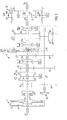
- Fig. 1 shows a schematic representation of one embodiment of a drive unit according to the invention
- Fig. 2 shows the clutch and the gearbox in Fig. 1 on a larger scale
- Fig. 3 shows an overview of inputs into the second control unit.
- Fig. 1, 1 designates a six-cylinder internal combustion engine, e.g. a diesel engine, the crankshaft 2 of which is coupled to a single-plate dry disk clutch which is designated generally by reference number 3 and is enclosed in a clutch case 4.
- a single-plate disk clutch a dual disk clutch can be used.
- the crankshaft 2 is connected non-rotatably to the clutch housing 5 of the clutch 3, while its disk plate 6 is connected non-rotatably to an input shaft 7, which is mounted rotatably in the casing 8 of a gearbox designated generally by reference number 9.
- a main shaft 10 and an intermediate shaft 11 are also mounted rotatably in the casing 8.
- first control unit 48 for controlling the engine
- second control unit 45 for controlling the transmission
- auxiliary brakes 60 are controlled from and second control unit via the first control unit 48.
- the auxiliary brakes can be for example compression brakes or exhaust brakes.
- the first and second control units (48 and 45, respectively) are adapted for communication with each other.
- a gear wheel 12 is mounted rotatably on the input shaft 7 and is lockable on the shaft by means of an engaging sleeve 13 which is provided with synchronizing means and is mounted non-rotatably but axially displaceably on a hub 14 connected non-rotatably to the input shaft 7.
- an engaging sleeve 13 which is provided with synchronizing means and is mounted non-rotatably but axially displaceably on a hub 14 connected non-rotatably to the input shaft 7.
- a gear wheel 15 mounted rotatably on the main shaft 10 is also lockable relative to the input shaft 7.
- the gear wheels 12 and 15 engage with gear wheels 16 and 17, respectively, which are connected non-rotatably to the intermediate shaft 11.
- gear wheels 18, 19 and 20 Arranged in a rotationally fixed manner on the intermediate shaft 11 are further gear wheels 18, 19 and 20 which engage with gear wheels 21, 22 and 23, respectively, which are mounted rotatably on the main shaft 10 and are lockable on the main shaft by means of engaging sleeves 24 and 25, respectively, which, in the illustrative embodiment shown, do not have synchronizing arrangements.
- a further gear wheel 28 is mounted rotatably on the main shaft 10 and engages with an intermediate gear wheel 30, which is mounted rotatably on a separate shaft 29 and engages in turn the intermediate shaft gear wheel 20.
- the gear wheel 28 is lockable on its shaft by means of an engaging sleeve 26.
- the gear wheel pairs 12, 16 and 15, 17 and also the engaging sleeve 13 form a split gearing with a low gear stage LS and a high gear stage HS.
- the gear wheel pair 15, 17 also forms, together with the gear wheel pairs 21, 18, 22, 19, 23, 20 and 28, 30, a basic gearbox with four forward gears and one reverse gear.
- a gear wheel 31 Arranged in a rotationally fixed manner on the output end of the main shaft is a gear wheel 31 which forms the sun gear in a two-stage range gear of the planetary type designated by reference number 32, the planet wheel carrier 33 of which is connected in a rotationally fixed manner to a shaft 34 which forms the output shaft of the gearbox.
- the planet wheels 35 of the range gear 32 engage with a ring gear 36, which, by means of an engaging sleeve 37, is lockable relative to the gearbox casing 8 for low range LR and relative to the planet wheel carrier 33 for high range HR.
- the engaging sleeve also has a neutral position NR between the gear positions LR and HR. In the neutral position NR the output shaft 34 is released from the main shaft 10.
- the engaging sleeves 13, 24, 25, 26 and 37 are displaceable as shown by the arrows in Fig. 2, to provide the gear stages shown next to the arrows.
- the displacement is brought about by servo devices 40, 41, 42, 43 and 44 which are indicated diagrammatically in Fig. 2 and may be pneumatically operated piston/cylinder arrangements of the type used in a gearbox of the type described above, which is marketed under the name Geartronic®.
- the servo devices are controlled by an electronic control unit 45 (Fig. 1), comprising a microcomputer, depending on signals fed into the control unit representing the various engine and vehicle data which comprise at least engine speed, vehicle speed, throttle pedal position and, in this case, engine brake on/off, when an electronic gear selector 46 coupled to the control unit 45 is in its automatic transmission position.
- the control unit 45 also controls fuel injection, that is to say the engine speed, depending on the throttle pedal position, and also the air supply to a pneumatic piston/cylinder arrangement 47, by means of which the clutch 3 is engaged and disengaged.
- the second control unit 45 is programmed in a known manner so that it keeps the clutch 3 engaged when the vehicle is standing still and the gear selector 46 is in the neutral position. This means that the engine drives the input shaft 7 and thus also the inter-mediate shaft, while the output shaft 34 is disengaged.
- An auxiliary unit e.g. an oil pump for lubricating the gearbox, can possibly be driven by the intermediate shaft in this position.
- the second control unit 45 is also programmed, when the vehicle is standing still and the gear selector is moved from the neutral position to a shift position, either to a position for automatic shifting or to a position with a start-off gear selected by the driver, to first release the clutch 3, then brake the intermediate shaft 11 to stop with the aid of the intermediate shaft brake 50, indicated in Fig.
- control unit 45 which can be a brake device, which can be known per se, controlled by the control unit 45.
- the control unit 45 With the intermediate shaft 11 braked to stop or at least nearly to stop, the control unit 45 now initiates the shift in the basic gearbox to a gear ratio which is provided by the automatic shifter or selected by the driver.
- the accelerator pedal When the driver, after engaging the gear, opens the throttle, the accelerator pedal functions as a reverse clutch pedal, which, via the control unit, gradually increases the clutch engagement with increasing throttle opening.
- Fig. 3 illustrates schematically input which the second control unit 45 needs to be able to make a decision to close the throttle opening or brake the vehicle in accordance with the present invention.
- the switch 300 is adapted for communication with the second control unit 45.
- An electronic map 340 for example stored on a CD-ROM (Compact Disc Read Only Memory) contains the information on a region's topology necessary for the computer simulation, i.e. at least gradients or elevation values for the route, with sea level as a reference, for example, and any information concerning speed limits along the route.
- the computer simulation uses parameters 320 sent from meters and sensors 310, in accordance with known technology.
- the second control unit 45 can compute (simulate over a certain, predetermined time) i.e. estimated, future required acceleration ( or retardation) and fuel consumption.
- Fig. 3 shows a symbol for GPS 330, which communicates with the second control unit, possibly also through the sensors 310. As an output from the second control unit 45, there is sent a decision 350, i.e, a controlling of the auxiliary brakes 60 for example or a throttle opening for the vehicle.
Abstract
Description
- The present invention relates to motor vehicle comprising an internal combustion engine and an electronic control unit for controlling the engine depending on the setting of a manual throttle, an electronic control unit for controlling the transmission, depending on a set position of a manual gear selector.
- In vehicles of this type there are today control units with a stored gear selector strategy, i.e. a time-based shifting sequence as a function of road incline, for example. A known technology is described in US-A-5 832 400. For vehicles with a conventional automatic transmission, where the transmission shifts sequentially with a torque converter, there is a gear selection strategy based on an algorithm which takes into account a measuring point in the topology surrounding the vehicle, with instantaneous vehicle position as a reference point. By determining, by various methods, where the vehicle will be after a certain time interval, it is possible to modify the engine setting and the shifting points for the automatic transmission, i.e. at which rpm the transmission should shift up or down. Possible variants could be to use electronic maps together with a positioning system (e.g. a Global Positioning System, GPS) or extrapolate a future position for the vehicle. One disadvantage of this system is that it does not take into consideration how the road varies in elevation between two points of measurement, and extreme points (e.g. the crest of a hill) between the two points of measurement are thus not taken into account in certain cases. The engine and the transmission are set in accordance with the known technology, on the basis of how great the difference in elevation is between the two points of measurement, and the instantaneous throttle position. Throttle position means in this case and in the following text both an adjustable cruise control and an accelerator pedal.
- US-A-5 832 400 only takes into consideration, as was mentioned, a single point of measurement during a certain time or distance into the future, in order to see if the instantaneous engine torque will be sufficient, or if the engine and/or transmission needs to be reset. It is also described how a plurality of points of measurement can be used but in that case a mean value thereof is used, thus providing one value for the required driving force. With a transmission which is shifted sequentially and with the method just described, there is an uncertainty in the system which results in tangible consequences in the form of less than satisfactory cruise control function, uneven acceleration and unnecessarily large exhaust emissions.
- The document EP 1 053 903 (preamble of claim 1) depicts a vehicular velocity controlling apparatus and methods to follow up a preceding vehicle which is running ahead of the vehicle with an appropriate inter-vehicle distance maintained. An inter-vehicle sensor which is constituted by a radar unit as an inter-vehicle distance detector which detects an inter-vehicle distance to the preceding vehicle is provided. As the inter-vehicle distance sensor, a range measurement instrument to measure an inter-vehicle distance can be applied utilizing the radar to measure the inter-vehicle distance which sweeps, e.g. a laser beam in a front width-wise direction and receives a reflected laser beam from any object, e.g. a preceding vehicle which is running ahead of the vehicle. The vehicle has a road surface gradient detector to detect a current descending slope on which the vehicle is running. The apparatus is arranged to control the speed of the vehicle taking in account the inter-vehicle distance from the vehicle to a preceding vehicle and present road slope.
- The document US-A-6 029 107 depicts a control apparatus of a conventional non-step type automatic transmission (CVT) for a vehicle. The apparatus allows to control the gear ratio automatically according to the condition of road surface so that effective engine brake suitable for a present road gradient can be automatically applied on the downhill and effective driving force suitable for the road gradient can be automatically obtained on the uphill. The apparatus is provided with a road gradient estimating part for estimating the gradient of road on which the vehicle is running, and a part for determining whether or not the estimate is beyond a predetermined threshold value, The controlling of the gear ratio is performed depending on if the gradient estimate is above the threshold value or not.
- Today; cruise controls function by controlling a throttle opening or a braking process, which is described in US 5 894731, until a selected or given target speed is reached. In practice this means that if a vehicle is moving downhill at a speed exceeding the target speed, the cruise control will attempt to brake the vehicle down to the target speed, regardless of the road incline after the end of the downhill stretch. This means that if, directly after the downhill stretch, there is an uphill incline, and the vehicle has been braked down to the target speed, the vehicle, if the uphill stretch is sufficiently steep, will move at below the target speed. The cruise control, in this situation, will compensate by greatly increasing the throttle opening and shifting down. Another example of the same type of problem is the case of the extension of the problem just described, where the vehicle is moving uphill at lower than target speed and reaches the crest, whereupon the continued open throttle will result in excess speed in the subsequent downhill stretch, and the vehicle will be forced to brake to once again reach the target speed.
- There are today other types of cruise controls, for example those which use radar and adjust the vehicle speed to traffic in front, or transponders mounted on road signs for example. In both cases the target speed of the vehicle is changed continually depending on the surrounding traffic, weather conditions, wild animals other dynamic or random parameters. The purpose of the present invention is to achieve a motor vehicle of the type described by way of introduction, which removes the above mentioned problems by providing a system and a method, which, with the aid of a cruise control function, controls throttle opening and braking, where the braking is effected using auxiliary brakes for example, to obtain lower vehicle fuel consumption. There are also achieved lower noise and exhaust emissions, more even acceleration and more comfortable cruising.
- This is achieved in a vehicle of the type described by way of introduction according to the invention by virtue of the fact that one of the control units is disposed, with fed-in parameters and thus at least knowledge of the target speed of the vehicle, the surrounding topology and the throttle opening position, to reduce the throttle opening, in those cases where the vehicle, relative to the target speed, has a speed below target speed and gravity can subsequently accelerate the vehicle, and to use the kinetic energy of the vehicle, in those cases where the vehicle has a speed above the target speed and gravity can subsequently retard the vehicle.
- In a preferred embodiment, the second control unit is disposed, under set preconditions, to perform computer simulations for a longer period forward (30 seconds or more), where the information on instantaneous position is obtained with the aid of GPS and/or where future positions are provided by information from an electronic map.
- In a second embodiment, with the aid of electronics and sensors, estimates, (extrapolations) can be made concerning road incline and information can thus be obtained on the topology surrounding the vehicle and its future position.
- The present invention is preferably intended for, but is not limited to, automated manual transmissions. A significant difference in relation to the known technology (Automated Power Transmission) referred to, is that shifting in the present case takes place with force interruption. There is thus a clear advantage of using the system according to the invention, otherwise it is not certain that shifting up in an up-hill incline will be successful, even if the driving force were theoretically sufficient because if the shifting takes too long, the vehicle will be retarded too much.
- With reference to the two cases (too low speed in an uphill incline and excessive speed in a downhill incline) which were exemplified previously, the present invention could in principle be summarized as follows:
- 1) At the request of the driver, with the aid of electronics and data from sensors, the second control unit, upon a decision based on a computer simulation, can deactivate applied auxiliary brakes, which would otherwise apply braking torque, when the vehicle, without the braking torque, would achieve reduced fuel consumption and/or increased average speed.
- 2) At the request of the driver, with the aid of electronics and data from sensors, the second control unit, upon a decision based on a computer simulation, can adjust the throttle opening of a cruise control to the current driving resistance of the vehicle and that in the immediate future (30 seconds or more).
- In order to additionally describe the present invention a few examples will be provided below of applications.
- The second control unit is disposed, with the aid of electronics and sensors, to limit the throttle opening when there are large speed deviations and when the road is inclined downhill.
- The second control unit is disposed, with the aid of electronics and sensors, to keep the throttle open when the vehicle speed is greater than that set in the cruise control and the vehicle is approaching an uphill incline in which the reduction in speed would be so great that the maximum engine torque would not be able to accelerate the vehicle before the vehicle speed has dropped to the target speed.
- The second control unit is disposed, with the aid of electronics and data from sensors, to adjust the throttle opening when the vehicle is approaching the end of an uphill incline, and where the vehicle speed is less than the target speed, gradually adjusting to a future lesser throttle opening.
- The second control unit, with the aid of electronics and sensors, is disposed to adjust the throttle opening, when the vehicle approaches the beginning of a downhill incline, to gradually adjust to a future lesser throttle opening, i.e. the throttle opening which together with gravity and driving resistance will accelerate the vehicle to the target speed within a predetermined time period.
- The second control unit, with the aid of electronics and sensors, is disposed to adjust possibly applied auxiliary brakes and possibly the throttle opening, as the vehicle approaches the end of a downhill incline, to a future greater throttle opening required to maintain the target speed.
- The second control unit, with the aid of electronics and sensors, is disposed to adjust possibly applied auxiliary brakes and possibly the throttle opening, as the vehicle approaches the end of a downhill incline, so as to permit a temporary increase in speed, the maximum level of which is predetermined in the second control unit.
- The second control unit, with the aid of electronics and sensors, is disposed to release the auxiliary brakes, when the vehicle approaches an uphill incline and where the vehicle speed exceeds the target speed, to not brake off energy since the retardation of the vehicle in the uphill incline will adapt the vehicle speed to the target speed.
- In the above description and in the following, it is stated that the various input data are fed into the second control unit which carries out the computer simulations. This function can, of course, also be taken over by the first control unit or at another physical location arranged for communication with the second control unit.
- The invention will be described in more detail below with reference to examples shown in the accompanying drawings, where Fig. 1 shows a schematic representation of one embodiment of a drive unit according to the invention, Fig. 2 shows the clutch and the gearbox in Fig. 1 on a larger scale, and Fig. 3 shows an overview of inputs into the second control unit.
- In Fig. 1, 1 designates a six-cylinder internal combustion engine, e.g. a diesel engine, the crankshaft 2 of which is coupled to a single-plate dry disk clutch which is designated generally by
reference number 3 and is enclosed in aclutch case 4. Instead of a single-plate disk clutch, a dual disk clutch can be used. The crankshaft 2 is connected non-rotatably to the clutch housing 5 of theclutch 3, while its disk plate 6 is connected non-rotatably to an input shaft 7, which is mounted rotatably in thecasing 8 of a gearbox designated generally by reference number 9. Amain shaft 10 and an intermediate shaft 11 are also mounted rotatably in thecasing 8. Further, there are illustrated afirst control unit 48 for controlling the engine, asecond control unit 45 for controlling the transmission and a manually operated electronic gear-speed selector 46, coupled to thesecond control unit 45.Auxiliary brakes 60 are controlled from and second control unit via thefirst control unit 48. The auxiliary brakes can be for example compression brakes or exhaust brakes. The first and second control units (48 and 45, respectively) are adapted for communication with each other. - As can be seen most clearly from Fig. 2, a
gear wheel 12 is mounted rotatably on the input shaft 7 and is lockable on the shaft by means of anengaging sleeve 13 which is provided with synchronizing means and is mounted non-rotatably but axially displaceably on a hub 14 connected non-rotatably to the input shaft 7. By means of theengaging sleeve 13, agear wheel 15 mounted rotatably on themain shaft 10 is also lockable relative to the input shaft 7. Thegear wheels gear wheels further gear wheels gear wheels main shaft 10 and are lockable on the main shaft by means ofengaging sleeves 24 and 25, respectively, which, in the illustrative embodiment shown, do not have synchronizing arrangements. Afurther gear wheel 28 is mounted rotatably on themain shaft 10 and engages with an intermediate gear wheel 30, which is mounted rotatably on aseparate shaft 29 and engages in turn the intermediate shaft gear wheel 20. Thegear wheel 28 is lockable on its shaft by means of anengaging sleeve 26. - The gear wheel pairs 12, 16 and 15, 17 and also the
engaging sleeve 13 form a split gearing with a low gear stage LS and a high gear stage HS. Thegear wheel pair gear wheel pairs gear wheel 31 which forms the sun gear in a two-stage range gear of the planetary type designated byreference number 32, the planet wheel carrier 33 of which is connected in a rotationally fixed manner to ashaft 34 which forms the output shaft of the gearbox. Theplanet wheels 35 of therange gear 32 engage with aring gear 36, which, by means of an engaging sleeve 37, is lockable relative to thegearbox casing 8 for low range LR and relative to the planet wheel carrier 33 for high range HR. The engaging sleeve also has a neutral position NR between the gear positions LR and HR. In the neutral position NR theoutput shaft 34 is released from themain shaft 10. - The engaging
sleeves servo devices control unit 45 is in its automatic transmission position. When the selector is in the position for manual shifting, shifting is effected via the gear selector 46 at the command of the driver. Thecontrol unit 45 also controls fuel injection, that is to say the engine speed, depending on the throttle pedal position, and also the air supply to a pneumatic piston/cylinder arrangement 47, by means of which theclutch 3 is engaged and disengaged. - The
second control unit 45 is programmed in a known manner so that it keeps the clutch 3 engaged when the vehicle is standing still and the gear selector 46 is in the neutral position. This means that the engine drives the input shaft 7 and thus also the inter-mediate shaft, while theoutput shaft 34 is disengaged. An auxiliary unit, e.g. an oil pump for lubricating the gearbox, can possibly be driven by the intermediate shaft in this position. Thesecond control unit 45 is also programmed, when the vehicle is standing still and the gear selector is moved from the neutral position to a shift position, either to a position for automatic shifting or to a position with a start-off gear selected by the driver, to first release theclutch 3, then brake the intermediate shaft 11 to stop with the aid of theintermediate shaft brake 50, indicated in Fig. 2, which can be a brake device, which can be known per se, controlled by thecontrol unit 45. With the intermediate shaft 11 braked to stop or at least nearly to stop, thecontrol unit 45 now initiates the shift in the basic gearbox to a gear ratio which is provided by the automatic shifter or selected by the driver. When the driver, after engaging the gear, opens the throttle, the accelerator pedal functions as a reverse clutch pedal, which, via the control unit, gradually increases the clutch engagement with increasing throttle opening. - Fig. 3 illustrates schematically input which the
second control unit 45 needs to be able to make a decision to close the throttle opening or brake the vehicle in accordance with the present invention. With onecontrol 300 for manual turning on or off of the present function, the driver can actively select the process. Theswitch 300 is adapted for communication with thesecond control unit 45. Anelectronic map 340, for example stored on a CD-ROM (Compact Disc Read Only Memory) contains the information on a region's topology necessary for the computer simulation, i.e. at least gradients or elevation values for the route, with sea level as a reference, for example, and any information concerning speed limits along the route. The computer simulation usesparameters 320 sent from meters andsensors 310, in accordance with known technology. These consist at least of vehicle or train weight, instantaneous vehicle speed, gear ratios, degrees of efficiency, engine rpm, throttle opening position (even throttle opening position change), instantaneous position, road incline (not from electronic map), ambient temperature (which affects the fuel/air mixture), driving resistance and the engine dynamics of the engine. With the necessary information, thesecond control unit 45 can compute (simulate over a certain, predetermined time) i.e. estimated, future required acceleration ( or retardation) and fuel consumption. Furthermore, Fig. 3 shows a symbol forGPS 330, which communicates with the second control unit, possibly also through thesensors 310. As an output from thesecond control unit 45, there is sent adecision 350, i.e, a controlling of theauxiliary brakes 60 for example or a throttle opening for the vehicle.
Claims (13)
- A motor vehicle comprising an internal combustion engine and a first electronic control unit (48) for controlling the engine depending on the setting of a manual throttle control, and a second electronic control unit (45) for controlling the transmission, depending on a set position of a manually operated electronic gear selector (46), characterized in that the vehicle is provided with a cruise control function arranged to control throttle opening and braking of the vehicle; means for providing information on instantaneous position of the vehicle with the aid of GPS; means for providing topology, information, wherein information about topology comprises information about gradients or elevation values for the route; wherein one of the control units is disposed, with fed-in parameters and thus at least knowledge of a set target speed of the vehicle, the surrounding topology and the throttle opening position, to reduce the throttle opening, in those cases where the vehicle, relative to the set target speed, has a speed below target speed and where a future gravity will subsequently accelerate the vehicle, and use the kinetic energy of the vehicle, in those cases where the vehicle has a speed above target speed and where a future gravity will subsequently retard the vehicle.
- Motor vehicle according to Claim 1, characterized in that the instantaneous vehicle position is determined by a GPS (350) (Global Positioning System) unit which is coupled to one of the control units for instantaneous determination of vehicle position.
- Motor vehicle according to Claim 2, characterized in that one of the control units is disposed to be given information from an electronic map (340) on the topology surrounding the vehicle.
- Motor vehicle according to Claim 1, characterized in that one of the control units is disposed to be given information from sensors (310), and, at least with knowledge of instantaneous vehicle position, speed and road incline, extrapolate through calculation, a future position of the vehicle.
- Motor vehicle according to Claim 1, characterized in that the engine is coupled to a clutch (3) and an automated transmission (9) between the engine and the driving wheels and is provided with at least an auxiliary brake.
- Motor vehicle according to Claim 1, characterized in that the derivative and acceleration of the throttle opening position, the instantaneous or extrapolated value, representing the intentions of the driver, also in combination with a cruise control function, are parameters in a computer simulation connected to a gear selection strategy.
- Motor vehicle according to Claim 1, characterized in that one of the control units is disposed, with the aid of electronics and sensors, to limit the throttle opening increase of a cruise control at great speed deviations and when the road is inclined downhill.
- Motor vehicle according to Claim 1, characterized in that one of the control units is disposed, with the aid of electronics and sensors, to keep the throttle open when the vehicle speed is greater than that set in the cruise control and the vehicle is approaching an uphill incline in which the reduction in speed would be so great that the maximum engine torque would not be able to accelerate the vehicle before the vehicle speed has dropped to the target speed.
- Motor vehicle according to Claim 1, characterized in that one of the control units is disposed, with the aid of electronics and data from sensors, to adjust the throttle opening when the vehicle is approaching the end of an uphill incline, and where the vehicle speed is less than the target speed, gradually adjusting to a future lesser throttle opening.
- Motor vehicle according to Claim 1, characterized in that one of the control units is disposed, with the aid of electronics and sensors, to adjust the throttle opening, when the vehicle approaches the beginning of a downhill incline, to gradually adjust to a future lesser throttle opening, i.e. the throttle opening which together with gravity and driving resistance will accelerate the vehicle to the target speed within a predetermined time period.
- Motor vehicle according to Claim 1, characterized in that one of the control units is disposed, with the aid of electronics and sensors, is disposed to adjust possibly applied auxiliary brakes and possibly the throttle opening, as the vehicle approaches the end of a downhill incline, to a future greater throttle opening required to maintain the target speed.
- Motor vehicle according to Claim 1, characterized in that one of the control units is disposed, with the aid of electronics and sensors, to adjust possibly applied auxiliary brakes and possibly the throttle opening, as the vehicle approaches the end of a downhill incline, so as to permit a temporary increase in speed, the maximum level of which is predetermined in the second control unit.
- Motor vehicle according to Claim 1, characterized in that one of the control units is disposed, with the aid of electronics and sensors, is disposed to release the auxiliary brakes, when the vehicle approaches an uphill incline and where the vehicle speed exceeds the target speed, to not brake off energy since the retardation of the vehicle in the uphill incline will adapt the vehicle speed to the target speed.
Applications Claiming Priority (3)
| Application Number | Priority Date | Filing Date | Title |
|---|---|---|---|
| SE0103630 | 2001-10-31 | ||
| SE0103630A SE520400C2 (en) | 2001-10-31 | 2001-10-31 | Cruise control in motor vehicles |
| PCT/SE2002/001969 WO2003041987A1 (en) | 2001-10-31 | 2002-10-30 | Cruise control for vehicle |
Publications (2)
| Publication Number | Publication Date |
|---|---|
| EP1439976A1 EP1439976A1 (en) | 2004-07-28 |
| EP1439976B1 true EP1439976B1 (en) | 2006-11-29 |
Family
ID=20285836
Family Applications (1)
| Application Number | Title | Priority Date | Filing Date |
|---|---|---|---|
| EP02803141A Expired - Lifetime EP1439976B1 (en) | 2001-10-31 | 2002-10-30 | Cruise control for vehicle |
Country Status (6)
| Country | Link |
|---|---|
| US (1) | US7225073B2 (en) |
| EP (1) | EP1439976B1 (en) |
| AT (1) | ATE346765T1 (en) |
| DE (1) | DE60216491T2 (en) |
| SE (1) | SE520400C2 (en) |
| WO (1) | WO2003041987A1 (en) |
Cited By (2)
| Publication number | Priority date | Publication date | Assignee | Title |
|---|---|---|---|---|
| EP1975029A1 (en) | 2007-03-27 | 2008-10-01 | Astrium GmbH | Device and method for automatic speed regulation of a vehicle |
| JP2013512138A (en) * | 2009-11-30 | 2013-04-11 | ボルボ ラストバグナー アーベー | Method and system for controlling vehicle cruise control |
Families Citing this family (24)
| Publication number | Priority date | Publication date | Assignee | Title |
|---|---|---|---|---|
| SE525479C2 (en) * | 2003-07-10 | 2005-03-01 | Volvo Lastvagnar Ab | Method for optimizing the braking process in vehicles |
| SE0400603L (en) | 2004-03-09 | 2005-01-25 | Volvo Lastvagnar Ab | Method and apparatus for distributing brake elements of a motor vehicle |
| DE102006009654A1 (en) * | 2006-03-02 | 2007-11-08 | Robert Bosch Gmbh | Device for switching on and off a vehicle engine depending on the traffic situation |
| US7424868B2 (en) * | 2006-05-15 | 2008-09-16 | Daimler Trucks North America Llc | Predictive auxiliary load management (PALM) control apparatus and method |
| US7347168B2 (en) * | 2006-05-15 | 2008-03-25 | Freightliner Llc | Predictive auxiliary load management (PALM) control apparatus and method |
| JP4314250B2 (en) * | 2006-05-23 | 2009-08-12 | トヨタ自動車株式会社 | Road surface determination device for vehicles |
| JP4713408B2 (en) * | 2006-06-07 | 2011-06-29 | トヨタ自動車株式会社 | Vehicle control device |
| SE530804C2 (en) * | 2007-01-30 | 2008-09-16 | Scania Cv Abp | Cruise control system and method for controlling the target speed thereof |
| JP2008239002A (en) * | 2007-03-28 | 2008-10-09 | Mitsubishi Fuso Truck & Bus Corp | Constant speed travelling device for vehicle |
| US8082089B2 (en) * | 2008-07-23 | 2011-12-20 | GM Global Technology Operations LLC | Vehicle speed control in a cruise mode using vehicle brakes |
| US8700256B2 (en) | 2008-08-22 | 2014-04-15 | Daimler Trucks North America Llc | Vehicle disturbance estimator and method |
| US8170770B2 (en) * | 2008-11-18 | 2012-05-01 | Bendix Commercial Vehicle Systems Llc | Adaptive cruise control braking with deceleration monitoring |
| SE533144C2 (en) | 2008-11-26 | 2010-07-06 | Scania Cv Abp | Determination of acceleration behavior |
| RU2521931C2 (en) | 2009-07-02 | 2014-07-10 | Вольво Ластвагнар Аб | Method and device for control over automatic carrier speed maintenance |
| WO2011076226A1 (en) | 2009-12-21 | 2011-06-30 | Volvo Lastvagnar Ab | Method and system for controlling a vehicle cruise control |
| US20110276216A1 (en) * | 2010-05-07 | 2011-11-10 | Texas Instruments Incorporated | Automotive cruise controls, circuits, systems and processes |
| CN103261619B (en) * | 2010-12-17 | 2015-07-29 | 沃尔沃拉斯特瓦格纳公司 | Control the method for the power drive system of vehicle |
| US8510012B2 (en) | 2010-12-22 | 2013-08-13 | Bendix Commercial Vehicle Systems Llc | Anti-tailgating system and method |
| US9393963B2 (en) | 2014-09-19 | 2016-07-19 | Paccar Inc | Predictive cruise control system with advanced operator control and feedback |
| US20160257295A1 (en) * | 2015-03-06 | 2016-09-08 | Ford Global Technologies, Llc | Systems and methods for adjusting kinetic energy in a hybrid vehicle before and during a change in road grade |
| US9702453B2 (en) | 2015-09-30 | 2017-07-11 | Lam Dinh | System and method for automatically shifting a vehicle |
| DE102016223016A1 (en) * | 2016-11-22 | 2018-05-24 | Zf Friedrichshafen Ag | Method for switching control of an automated group transmission |
| KR20180084228A (en) * | 2017-01-16 | 2018-07-25 | 현대자동차주식회사 | Cruise control system and vehicle comprising the same, control method of the cruise control system |
| US10940862B1 (en) | 2019-09-05 | 2021-03-09 | Cummins Inc. | Speed limiting of vehicles equipped with engine brakes |
Family Cites Families (7)
| Publication number | Priority date | Publication date | Assignee | Title |
|---|---|---|---|---|
| US5272939B1 (en) * | 1992-07-06 | 1994-12-06 | Eaton Corp | Shift enable control method/system |
| US5335566A (en) * | 1992-07-06 | 1994-08-09 | Eaton Corporation | Shift control method/system |
| JP3203976B2 (en) * | 1994-09-05 | 2001-09-04 | 日産自動車株式会社 | Vehicle driving force control device |
| US5659304A (en) * | 1995-03-01 | 1997-08-19 | Eaton Corporation | System and method for collision warning based on dynamic deceleration capability using predicted road load |
| KR970066191A (en) * | 1996-03-01 | 1997-10-13 | 가나이 쯔도무 | Control device and control method of automatic transmission |
| DE60016500T2 (en) * | 1999-05-20 | 2006-01-05 | Nissan Motor Co., Ltd., Yokohama | Distance-related cruise control system |
| US7640081B2 (en) * | 2004-10-01 | 2009-12-29 | Ford Global Technologies, Llc | Roll stability control using four-wheel drive |
-
2001
- 2001-10-31 SE SE0103630A patent/SE520400C2/en not_active IP Right Cessation
-
2002
- 2002-10-30 EP EP02803141A patent/EP1439976B1/en not_active Expired - Lifetime
- 2002-10-30 US US10/494,446 patent/US7225073B2/en not_active Expired - Lifetime
- 2002-10-30 AT AT02803141T patent/ATE346765T1/en not_active IP Right Cessation
- 2002-10-30 WO PCT/SE2002/001969 patent/WO2003041987A1/en active IP Right Grant
- 2002-10-30 DE DE60216491T patent/DE60216491T2/en not_active Expired - Lifetime
Cited By (2)
| Publication number | Priority date | Publication date | Assignee | Title |
|---|---|---|---|---|
| EP1975029A1 (en) | 2007-03-27 | 2008-10-01 | Astrium GmbH | Device and method for automatic speed regulation of a vehicle |
| JP2013512138A (en) * | 2009-11-30 | 2013-04-11 | ボルボ ラストバグナー アーベー | Method and system for controlling vehicle cruise control |
Also Published As
| Publication number | Publication date |
|---|---|
| US7225073B2 (en) | 2007-05-29 |
| DE60216491T2 (en) | 2007-06-21 |
| SE520400C2 (en) | 2003-07-08 |
| ATE346765T1 (en) | 2006-12-15 |
| EP1439976A1 (en) | 2004-07-28 |
| SE0103630D0 (en) | 2001-10-31 |
| WO2003041987A1 (en) | 2003-05-22 |
| SE0103630L (en) | 2003-05-01 |
| DE60216491D1 (en) | 2007-01-11 |
| US20050085974A1 (en) | 2005-04-21 |
Similar Documents
| Publication | Publication Date | Title |
|---|---|---|
| EP1439976B1 (en) | Cruise control for vehicle | |
| EP1439975B1 (en) | Motor vehicle having an automated transmission | |
| US7469178B2 (en) | Deceleration control apparatus and method for a vehicle | |
| EP1031768B1 (en) | Control system for transmissions | |
| EP1174303B1 (en) | Control method and system for vehicle starting | |
| US8527163B2 (en) | Gearbox control device | |
| US7400964B2 (en) | Deceleration control apparatus and method for a vehicle | |
| JP5726896B2 (en) | Method and system for driving a vehicle | |
| US20150166064A1 (en) | Vehicle control system | |
| JPH10184877A (en) | Controller for stepped transmission | |
| SE525309C2 (en) | Automatic freewheel method for lorry with automatic gearbox, deactivates freewheeling and activating brakes when given maximum vehicle speed is exceeded | |
| CN1328101C (en) | Method and system for determining the torque required to launch a vehicle having a hybrid drive-train | |
| CN112406849A (en) | Steep descent control system for hybrid/electric vehicle | |
| US20040261557A1 (en) | Gear box for motor vehicles | |
| JP2005226671A (en) | Vehicle travel control device | |
| US20060162475A1 (en) | Drive means for motor vehicles | |
| SE2050625A1 (en) | Method and control arrangement in a vehicle approaching an uphill slope | |
| JP3417209B2 (en) | Control device for automatic transmission | |
| Jia | An approach for heavy-duty vehicle-level engine brake performance evaluation | |
| JP3239538B2 (en) | Engine brake control device for automatic transmission | |
| JP3720907B2 (en) | Automatic transmission control device for vehicle | |
| CN115103972A (en) | Method for downshifting gears in an uphill slope, computer program, computer-readable medium, control device and vehicle | |
| CN115552106A (en) | Method for engine braking and powertrain | |
| JP2000055185A (en) | Slip control device for lockup clutch |
Legal Events
| Date | Code | Title | Description |
|---|---|---|---|
| PUAI | Public reference made under article 153(3) epc to a published international application that has entered the european phase |
Free format text: ORIGINAL CODE: 0009012 |
|
| 17P | Request for examination filed |
Effective date: 20040428 |
|
| AK | Designated contracting states |
Kind code of ref document: A1 Designated state(s): AT BE BG CH CY CZ DE DK EE ES FI FR GB GR IE IT LI LU MC NL PT SE SK TR |
|
| AX | Request for extension of the european patent |
Extension state: AL LT LV MK RO SI |
|
| RIN1 | Information on inventor provided before grant (corrected) |
Inventor name: HEDMAN, ANDERS Inventor name: ERIKSSON, ANDERS Inventor name: STE N, MARCUS |
|
| GRAP | Despatch of communication of intention to grant a patent |
Free format text: ORIGINAL CODE: EPIDOSNIGR1 |
|
| RIN1 | Information on inventor provided before grant (corrected) |
Inventor name: ERIKSSON, ANDERS Inventor name: HEDMAN, ANDERS Inventor name: STEEN, MARCUS |
|
| GRAS | Grant fee paid |
Free format text: ORIGINAL CODE: EPIDOSNIGR3 |
|
| GRAA | (expected) grant |
Free format text: ORIGINAL CODE: 0009210 |
|
| AK | Designated contracting states |
Kind code of ref document: B1 Designated state(s): AT BE BG CH CY CZ DE DK EE ES FI FR GB GR IE IT LI LU MC NL PT SE SK TR |
|
| PG25 | Lapsed in a contracting state [announced via postgrant information from national office to epo] |
Ref country code: CZ Free format text: LAPSE BECAUSE OF FAILURE TO SUBMIT A TRANSLATION OF THE DESCRIPTION OR TO PAY THE FEE WITHIN THE PRESCRIBED TIME-LIMIT Effective date: 20061129 Ref country code: CH Free format text: LAPSE BECAUSE OF FAILURE TO SUBMIT A TRANSLATION OF THE DESCRIPTION OR TO PAY THE FEE WITHIN THE PRESCRIBED TIME-LIMIT Effective date: 20061129 Ref country code: BE Free format text: LAPSE BECAUSE OF FAILURE TO SUBMIT A TRANSLATION OF THE DESCRIPTION OR TO PAY THE FEE WITHIN THE PRESCRIBED TIME-LIMIT Effective date: 20061129 Ref country code: AT Free format text: LAPSE BECAUSE OF FAILURE TO SUBMIT A TRANSLATION OF THE DESCRIPTION OR TO PAY THE FEE WITHIN THE PRESCRIBED TIME-LIMIT Effective date: 20061129 Ref country code: IT Free format text: LAPSE BECAUSE OF FAILURE TO SUBMIT A TRANSLATION OF THE DESCRIPTION OR TO PAY THE FEE WITHIN THE PRESCRIBED TIME-LIMIT;WARNING: LAPSES OF ITALIAN PATENTS WITH EFFECTIVE DATE BEFORE 2007 MAY HAVE OCCURRED AT ANY TIME BEFORE 2007. THE CORRECT EFFECTIVE DATE MAY BE DIFFERENT FROM THE ONE RECORDED. Effective date: 20061129 Ref country code: SK Free format text: LAPSE BECAUSE OF FAILURE TO SUBMIT A TRANSLATION OF THE DESCRIPTION OR TO PAY THE FEE WITHIN THE PRESCRIBED TIME-LIMIT Effective date: 20061129 Ref country code: FI Free format text: LAPSE BECAUSE OF FAILURE TO SUBMIT A TRANSLATION OF THE DESCRIPTION OR TO PAY THE FEE WITHIN THE PRESCRIBED TIME-LIMIT Effective date: 20061129 Ref country code: LI Free format text: LAPSE BECAUSE OF FAILURE TO SUBMIT A TRANSLATION OF THE DESCRIPTION OR TO PAY THE FEE WITHIN THE PRESCRIBED TIME-LIMIT Effective date: 20061129 Ref country code: NL Free format text: LAPSE BECAUSE OF FAILURE TO SUBMIT A TRANSLATION OF THE DESCRIPTION OR TO PAY THE FEE WITHIN THE PRESCRIBED TIME-LIMIT Effective date: 20061129 |
|
| REG | Reference to a national code |
Ref country code: GB Ref legal event code: FG4D |
|
| REG | Reference to a national code |
Ref country code: CH Ref legal event code: EP |
|
| REG | Reference to a national code |
Ref country code: IE Ref legal event code: FG4D |
|
| REF | Corresponds to: |
Ref document number: 60216491 Country of ref document: DE Date of ref document: 20070111 Kind code of ref document: P |
|
| PG25 | Lapsed in a contracting state [announced via postgrant information from national office to epo] |
Ref country code: SE Free format text: LAPSE BECAUSE OF FAILURE TO SUBMIT A TRANSLATION OF THE DESCRIPTION OR TO PAY THE FEE WITHIN THE PRESCRIBED TIME-LIMIT Effective date: 20070228 Ref country code: BG Free format text: LAPSE BECAUSE OF FAILURE TO SUBMIT A TRANSLATION OF THE DESCRIPTION OR TO PAY THE FEE WITHIN THE PRESCRIBED TIME-LIMIT Effective date: 20070228 Ref country code: DK Free format text: LAPSE BECAUSE OF FAILURE TO SUBMIT A TRANSLATION OF THE DESCRIPTION OR TO PAY THE FEE WITHIN THE PRESCRIBED TIME-LIMIT Effective date: 20070228 |
|
| PG25 | Lapsed in a contracting state [announced via postgrant information from national office to epo] |
Ref country code: ES Free format text: LAPSE BECAUSE OF FAILURE TO SUBMIT A TRANSLATION OF THE DESCRIPTION OR TO PAY THE FEE WITHIN THE PRESCRIBED TIME-LIMIT Effective date: 20070312 |
|
| PG25 | Lapsed in a contracting state [announced via postgrant information from national office to epo] |
Ref country code: PT Free format text: LAPSE BECAUSE OF FAILURE TO SUBMIT A TRANSLATION OF THE DESCRIPTION OR TO PAY THE FEE WITHIN THE PRESCRIBED TIME-LIMIT Effective date: 20070430 |
|
| NLV1 | Nl: lapsed or annulled due to failure to fulfill the requirements of art. 29p and 29m of the patents act | ||
| REG | Reference to a national code |
Ref country code: CH Ref legal event code: PL |
|
| ET | Fr: translation filed | ||
| PLBE | No opposition filed within time limit |
Free format text: ORIGINAL CODE: 0009261 |
|
| STAA | Information on the status of an ep patent application or granted ep patent |
Free format text: STATUS: NO OPPOSITION FILED WITHIN TIME LIMIT |
|
| 26N | No opposition filed |
Effective date: 20070830 |
|
| PG25 | Lapsed in a contracting state [announced via postgrant information from national office to epo] |
Ref country code: GR Free format text: LAPSE BECAUSE OF FAILURE TO SUBMIT A TRANSLATION OF THE DESCRIPTION OR TO PAY THE FEE WITHIN THE PRESCRIBED TIME-LIMIT Effective date: 20070301 |
|
| PG25 | Lapsed in a contracting state [announced via postgrant information from national office to epo] |
Ref country code: MC Free format text: LAPSE BECAUSE OF NON-PAYMENT OF DUE FEES Effective date: 20071031 |
|
| GBPC | Gb: european patent ceased through non-payment of renewal fee |
Effective date: 20071030 |
|
| PG25 | Lapsed in a contracting state [announced via postgrant information from national office to epo] |
Ref country code: IE Free format text: LAPSE BECAUSE OF NON-PAYMENT OF DUE FEES Effective date: 20071030 |
|
| PG25 | Lapsed in a contracting state [announced via postgrant information from national office to epo] |
Ref country code: GB Free format text: LAPSE BECAUSE OF NON-PAYMENT OF DUE FEES Effective date: 20071030 |
|
| PG25 | Lapsed in a contracting state [announced via postgrant information from national office to epo] |
Ref country code: EE Free format text: LAPSE BECAUSE OF FAILURE TO SUBMIT A TRANSLATION OF THE DESCRIPTION OR TO PAY THE FEE WITHIN THE PRESCRIBED TIME-LIMIT Effective date: 20061129 |
|
| PG25 | Lapsed in a contracting state [announced via postgrant information from national office to epo] |
Ref country code: CY Free format text: LAPSE BECAUSE OF FAILURE TO SUBMIT A TRANSLATION OF THE DESCRIPTION OR TO PAY THE FEE WITHIN THE PRESCRIBED TIME-LIMIT Effective date: 20061129 Ref country code: LU Free format text: LAPSE BECAUSE OF NON-PAYMENT OF DUE FEES Effective date: 20071030 |
|
| PG25 | Lapsed in a contracting state [announced via postgrant information from national office to epo] |
Ref country code: TR Free format text: LAPSE BECAUSE OF FAILURE TO SUBMIT A TRANSLATION OF THE DESCRIPTION OR TO PAY THE FEE WITHIN THE PRESCRIBED TIME-LIMIT Effective date: 20061129 |
|
| REG | Reference to a national code |
Ref country code: FR Ref legal event code: PLFP Year of fee payment: 14 |
|
| REG | Reference to a national code |
Ref country code: FR Ref legal event code: PLFP Year of fee payment: 15 |
|
| REG | Reference to a national code |
Ref country code: FR Ref legal event code: PLFP Year of fee payment: 16 |
|
| REG | Reference to a national code |
Ref country code: FR Ref legal event code: PLFP Year of fee payment: 17 |
|
| REG | Reference to a national code |
Ref country code: DE Ref legal event code: R008 Ref document number: 60216491 Country of ref document: DE Ref country code: DE Ref legal event code: R039 Ref document number: 60216491 Country of ref document: DE |
|
| PGFP | Annual fee paid to national office [announced via postgrant information from national office to epo] |
Ref country code: DE Payment date: 20211027 Year of fee payment: 20 |
|
| PGFP | Annual fee paid to national office [announced via postgrant information from national office to epo] |
Ref country code: FR Payment date: 20211027 Year of fee payment: 20 |
|
| REG | Reference to a national code |
Ref country code: DE Ref legal event code: R071 Ref document number: 60216491 Country of ref document: DE |