EP1436110B1 - Outil de coupe - Google Patents
Outil de coupe Download PDFInfo
- Publication number
- EP1436110B1 EP1436110B1 EP02775176A EP02775176A EP1436110B1 EP 1436110 B1 EP1436110 B1 EP 1436110B1 EP 02775176 A EP02775176 A EP 02775176A EP 02775176 A EP02775176 A EP 02775176A EP 1436110 B1 EP1436110 B1 EP 1436110B1
- Authority
- EP
- European Patent Office
- Prior art keywords
- cutting
- insert
- cutting edge
- tool according
- cutting tool
- Prior art date
- Legal status (The legal status is an assumption and is not a legal conclusion. Google has not performed a legal analysis and makes no representation as to the accuracy of the status listed.)
- Expired - Lifetime
Links
Images


Classifications
-
- B—PERFORMING OPERATIONS; TRANSPORTING
- B23—MACHINE TOOLS; METAL-WORKING NOT OTHERWISE PROVIDED FOR
- B23C—MILLING
- B23C5/00—Milling-cutters
- B23C5/16—Milling-cutters characterised by physical features other than shape
- B23C5/20—Milling-cutters characterised by physical features other than shape with removable cutter bits or teeth or cutting inserts
- B23C5/22—Securing arrangements for bits or teeth or cutting inserts
- B23C5/2204—Securing arrangements for bits or teeth or cutting inserts with cutting inserts clamped against the walls of the recess in the cutter body by a clamping member acting upon the wall of a hole in the insert
- B23C5/2208—Securing arrangements for bits or teeth or cutting inserts with cutting inserts clamped against the walls of the recess in the cutter body by a clamping member acting upon the wall of a hole in the insert for plate-like cutting inserts
- B23C5/2213—Securing arrangements for bits or teeth or cutting inserts with cutting inserts clamped against the walls of the recess in the cutter body by a clamping member acting upon the wall of a hole in the insert for plate-like cutting inserts having a special shape
-
- B—PERFORMING OPERATIONS; TRANSPORTING
- B23—MACHINE TOOLS; METAL-WORKING NOT OTHERWISE PROVIDED FOR
- B23C—MILLING
- B23C2200/00—Details of milling cutting inserts
- B23C2200/04—Overall shape
- B23C2200/0405—Hexagonal
- B23C2200/0411—Hexagonal irregular
-
- B—PERFORMING OPERATIONS; TRANSPORTING
- B23—MACHINE TOOLS; METAL-WORKING NOT OTHERWISE PROVIDED FOR
- B23C—MILLING
- B23C2200/00—Details of milling cutting inserts
- B23C2200/16—Supporting or bottom surfaces
- B23C2200/161—Supporting or bottom surfaces with projections
-
- B—PERFORMING OPERATIONS; TRANSPORTING
- B23—MACHINE TOOLS; METAL-WORKING NOT OTHERWISE PROVIDED FOR
- B23C—MILLING
- B23C2210/00—Details of milling cutters
- B23C2210/16—Fixation of inserts or cutting bits in the tool
- B23C2210/168—Seats for cutting inserts, supports for replacable cutting bits
-
- Y—GENERAL TAGGING OF NEW TECHNOLOGICAL DEVELOPMENTS; GENERAL TAGGING OF CROSS-SECTIONAL TECHNOLOGIES SPANNING OVER SEVERAL SECTIONS OF THE IPC; TECHNICAL SUBJECTS COVERED BY FORMER USPC CROSS-REFERENCE ART COLLECTIONS [XRACs] AND DIGESTS
- Y10—TECHNICAL SUBJECTS COVERED BY FORMER USPC
- Y10T—TECHNICAL SUBJECTS COVERED BY FORMER US CLASSIFICATION
- Y10T407/00—Cutters, for shaping
- Y10T407/19—Rotary cutting tool
- Y10T407/1906—Rotary cutting tool including holder [i.e., head] having seat for inserted tool
- Y10T407/1908—Face or end mill
- Y10T407/191—Plural simultaneously usable separable tools in common seat or common clamp actuator for plural simultaneously usable tools
-
- Y—GENERAL TAGGING OF NEW TECHNOLOGICAL DEVELOPMENTS; GENERAL TAGGING OF CROSS-SECTIONAL TECHNOLOGIES SPANNING OVER SEVERAL SECTIONS OF THE IPC; TECHNICAL SUBJECTS COVERED BY FORMER USPC CROSS-REFERENCE ART COLLECTIONS [XRACs] AND DIGESTS
- Y10—TECHNICAL SUBJECTS COVERED BY FORMER USPC
- Y10T—TECHNICAL SUBJECTS COVERED BY FORMER US CLASSIFICATION
- Y10T407/00—Cutters, for shaping
- Y10T407/19—Rotary cutting tool
- Y10T407/1906—Rotary cutting tool including holder [i.e., head] having seat for inserted tool
- Y10T407/1908—Face or end mill
- Y10T407/192—Face or end mill with separate means to fasten tool to holder
-
- Y—GENERAL TAGGING OF NEW TECHNOLOGICAL DEVELOPMENTS; GENERAL TAGGING OF CROSS-SECTIONAL TECHNOLOGIES SPANNING OVER SEVERAL SECTIONS OF THE IPC; TECHNICAL SUBJECTS COVERED BY FORMER USPC CROSS-REFERENCE ART COLLECTIONS [XRACs] AND DIGESTS
- Y10—TECHNICAL SUBJECTS COVERED BY FORMER USPC
- Y10T—TECHNICAL SUBJECTS COVERED BY FORMER US CLASSIFICATION
- Y10T407/00—Cutters, for shaping
- Y10T407/19—Rotary cutting tool
- Y10T407/1906—Rotary cutting tool including holder [i.e., head] having seat for inserted tool
- Y10T407/1934—Rotary cutting tool including holder [i.e., head] having seat for inserted tool with separate means to fasten tool to holder
- Y10T407/1936—Apertured tool
-
- Y—GENERAL TAGGING OF NEW TECHNOLOGICAL DEVELOPMENTS; GENERAL TAGGING OF CROSS-SECTIONAL TECHNOLOGIES SPANNING OVER SEVERAL SECTIONS OF THE IPC; TECHNICAL SUBJECTS COVERED BY FORMER USPC CROSS-REFERENCE ART COLLECTIONS [XRACs] AND DIGESTS
- Y10—TECHNICAL SUBJECTS COVERED BY FORMER USPC
- Y10T—TECHNICAL SUBJECTS COVERED BY FORMER US CLASSIFICATION
- Y10T407/00—Cutters, for shaping
- Y10T407/23—Cutters, for shaping including tool having plural alternatively usable cutting edges
-
- Y—GENERAL TAGGING OF NEW TECHNOLOGICAL DEVELOPMENTS; GENERAL TAGGING OF CROSS-SECTIONAL TECHNOLOGIES SPANNING OVER SEVERAL SECTIONS OF THE IPC; TECHNICAL SUBJECTS COVERED BY FORMER USPC CROSS-REFERENCE ART COLLECTIONS [XRACs] AND DIGESTS
- Y10—TECHNICAL SUBJECTS COVERED BY FORMER USPC
- Y10T—TECHNICAL SUBJECTS COVERED BY FORMER US CLASSIFICATION
- Y10T407/00—Cutters, for shaping
- Y10T407/24—Cutters, for shaping with chip breaker, guide or deflector
- Y10T407/245—Cutters, for shaping with chip breaker, guide or deflector comprising concave surface in cutting face of tool
Definitions
- the present invention relates to a cutting tool and particularly to a milling cutting tool capable of performing face milling operations at a high feed rate and a long tool shank.
- the invention also discloses an indexable cutting insert for use with the cutting tool.
- JP-A-2000 3089 08 discloses a cutting tool having a longitudinal axis, the cutting tool comprising a tool body, having a mounting leg formed at a front end thereof, the mounting leg having an insert pocket with a cutting insert retained therein; the insert pocket comprising a base wall and first and second rear sidewall sections transversely directed to the base wall, the cutting insert comprising an upper surface, a lower surface and a side surface extending therebetween, the upper and side surfaces intersecting at a cutting edge.
- Japanese Publication No. 2000202703 A to Masaharu discloses a boring tool having two identical nearly parallelogrammatic plate form tips.
- Each tip has a pair of first cutting edges 15 and a pair of second cutting edges 16 arranged in a rotational symmetry and connected via a nose part 17.
- the first cutting edge 15 having a circular arcing cutting edge 15a at the side of the nose part 17 and a rectilinear cutting edge 15b merging with the cutting edge 15a via a first bending part 15.
- the second cutting edge 16 having two rectilinear cutting edges 16a and 16b merging via a second bending part 16c.
- each of the tips used in '703 is disposed differently with respect to the tool since each of the cutting edges has different characteristics. Since the cutting edges are arranged in 180° rotational symmetry, each tip can be indexed only two times at its pocket. Furthermore, if the tips used in '703 are used to perform ramp-down milling they are not properly supported against radially outwardly directed cutting forces that tend to withdraw each tip out of its pocket.
- Japanese Publication No. 2000-005921 to Yoshimitsu shows, in Fig. 4 thereof, a three-comer cutting insert.
- Each of the three cutting edges comprises a small curved cutting edge portion 7 and a large straight cutting edge portion 8.
- the cutting insert of '921 does not have a cutting edge specifically designed for performing ramp-down milling. Furthermore, the cutting insert is not properly supported against radially outwardly directed cutting forces that tend to withdraw the cutting insert out of its pocket during a ramp-down milling operation.
- FIG. 1 Another kind of tool, having means for preventing rotation of the cutting insert around the axis of the clamping screw, is shown in European Patent No. EP 0 091 408 B1 to Bylund.
- a cutting insert 12 having three convex cutting edges 16, 17 and 18. Each of the cutting edges is connected, at a rear end thereof, to an auxiliary cutting edge 32, which extends transversely to the cutting edge and forms an obtuse angle therewith.
- the auxiliary cutting edge 32 is intended to cut the workpiece during reversed relative movement between the insert and the workpiece.
- the cutting edges of the cutting insert 12 are not peripherally continuous around the top face of the cutting insert. Instead, they are separated by an intermediate peripheral space 24, 25 and 26.
- the cutting insert 12 is not provided with a cutting edge for performing ramp-down milling operations and is not especially supported against radially outwardly directed cutting forces that tend to withdraw the cutting insert out of its pocket.
- the cutting insert is provided with a supporting surface 27 that is directed substantially towards the center of the cutting insert. The supporting surface 27 abuts against an abutment surface 28 on the tool body that fits into the intermediate peripheral surface.
- a disadvantage of the tool of '408 is that in order to prevent rotation of the cutting insert, the cutting edges are formed with recesses which complicate and weaken the cutting insert.
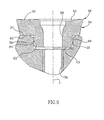
- a cutting tool (10) having a longitudinal axis (A) the cutting tool comprises a tool body (12), having at least one mounting leg (14) formed at a front end (16) thereof, the at least one mounting leg (14) having an insert pocket (18) with a cutting insert (20) retained therein;
- the insert pocket comprises a base wall (24) and first and second rear sidewall sections (40, 42) transversely directed to the base wall (24), a generally circular recess (28) extends downwardly from the base wall (24), the recess has a lower wall (30) bounded by a peripheral wall (32) extending uprightly from the lower wall (30) to the base wall (24),
- the cutting insert comprises an upper surface (60), a lower surface (62) and a side surface (64) extending therebetween, the upper and side surfaces (60, 64) intersecting at a cutting edge (66), a cylindrical protrusion (82) having a cylindrical peripheral surface (84) extends downwardly from the lower surface (62) to a bottom surface (86) of the
- the cutting edge (66) comprises at least three cutting edge portions (68) that are separated from each other by corner cutting edges (70) and each cutting edge portion comprises a first cutting edge (72) that extends between a second cutting edge (74) and an adjacent corner cutting edge (70).
- the first cutting edge (72) is convex.
- the second cutting edge (74) is straight.
- the side surface (64) comprises side surface sections with a first side surface section (76) adjacent the first cutting edge (72), a second side surface section (78) adjacent the second cutting edge (74) and a side surface corner section (80) adjacent the corner cutting edge (70), each of the side surface sections extending from its associated cutting edge towards the lower surface (62).
- first and second rear sidewall sections (40, 42) are separated by a first recessed region (44).
- first support surface (52') and the second support surface (56') are located on either side of a common side surface corner section (80).
- a portion of the common side surface corner section (80) is located in the first recessed region (44).
- the minor radius R2 is smaller than the major radius R1.
- the angular extent of the minor portion (36) is smaller than the angular extent of the major portion (34).
- a threaded bore (38) extends downwardly from the lower wall (30) of the recess (28).
- a through bore (88), having an insert axis (B), extends between the upper surface (60) of the cutting insert (20) and the bottom surface (86) of the protrusion (82).
- a retaining screw (22) is located in the through bore (88) and threadingly engages the threaded bore (38).
- first cutting edge (72) subtends a first angle ( ⁇ ) of 70° with the insert axis (B).
- the second cutting edge (74) subtends a second angle ( ⁇ ) of 35° with the insert axis.
- the first cutting edge (72) forms an obtuse interior third angle ( ⁇ ) with the adjacent second cutting edge (74).
- the third angle is 153°.
- the insert pocket comprises a base wall 24 and a sidewall 26 that is transversely directed to the base wall 24.
- a generally circular recess 28 extends downwardly from the base wall 24.
- the recess 28 has a lower wall 30 bounded by a peripheral wall 32 extending uprightly from the lower wall 30 to the base wall 24.
- the peripheral wall 32 of the recess 28 preferably comprises two circular portions of differing radii, but having the same center.
- the peripheral wall 32 comprises a major portion 34 having a major radius R1, and a minor portion 36 having a minor radius R2.
- the minor radius R2 is smaller than the major radius R1. According to a specific application of the present invention, the minor radius R2 is 0.25 mm smaller than the major radius R1.
- the angular extent of the minor portion 36 is smaller than the angular extent of the major portion 34.
- the minor portion 36 of the peripheral wall 32 has an angular extent ⁇ of approximately 40°.
- a threaded bore 38, having a pocket axis C, for receiving the retaining screw 22, extends downwardly from the lower wall 30 of the recess 28. The centers of the two circles on which the major and minor portions 34, 36 lie coincide with the axis C.
- the sidewall 26 comprises three sidewall sections, two rear sidewall sections, a first rear sidewall section 40 and a second rear sidewall section 42 separated by a first recessed region 44 and a side sidewall section 46.
- the first rear sidewall section 40 is adjacent the side sidewall section 46 and separated from it by a second recessed region 48.
- the first rear sidewall section 40 has a region 50 adjacent the first recessed region 44, at least a portion of which constitutes a first abutment surface 52 for abutting the cutting insert 20.
- the second rear sidewall section 42 has a region 54 adjacent the first recessed region 44, at least a portion of which constitutes a second abutment surface 56 for abutting the cutting insert 20.
- the minor portion 36 constitutes a third abutment surface 58 for abutting the cutting insert 20.
- the first, second and third abutment surfaces are designed to retain the cutting insert 20 in the insert pocket 18 in a well defined and secure manner.
- Fig. 5 Attention is drawn to Fig. 5. It will be noted that the minor portion 36, and therefore the third abutment surface 58, is located adjacent the side sidewall 46 towards the front of the insert pocket 18. In terms of an analog clock, the minor portion is located approximately between 7 and 8 O' clock. It will be appreciated that the precise location of the minor portion 36 is a question of design and distribution of forces. In practice, the illustrated location of the minor portion 36 is a preferred location. However, it can also be located at other locations between the preferred location up to approximately adjacent the second recessed region 48.
- the cutting insert 20 comprises an upper surface 60, a lower surface 62 and a side surface 64 that extends between the upper and lower surfaces 60, 62.
- the upper surface 60 and the side surface 64 intersect at a cutting edge 66 comprising three cutting edge portions 68 separated from each other by corner cutting edges 70.
- Each of the three cutting edge portions comprises a convex first cutting edge 72 that extends between a straight second cutting edge 74 and an adjacent corner cutting edge 70.
- the side surface 64 is divided into sections corresponding to the various cutting edges. Accordingly, the side surface 64 has a first side surface section 76 adjacent the first cutting edge 72, a second side surface section 78 adjacent the second cutting edge 74 and side surface corner section 80 adjacent corner cutting edge 70.
- a cylindrical protrusion 82 having a cylindrical peripheral surface 84 extends downwardly from the lower surface 62 to a bottom surface 86 of the protrusion 82.
- the peripheral surface 84 is perpendicular to the lower surface 62.
- a centrally located through bore 88, having an insert axis B, extends between the upper surface 60 and the bottom surface 86.
- the protrusion 82 has a protrusion radius R3.
- the protrusion radius R3 is smaller than the major radius R1 and approximately equal to the minor radius R2.
- the protrusion 82 is inserted into the recess 28 until the lower surface 62 of the cutting insert abuts the base wall 24 of the insert pocket, with a portion of a given side surface corner section 80 located in the first recessed region 44.
- the retaining screw 22 is then placed in the through bore 88 of the cutting insert and threadingly engaged with the threaded bore 38 and tightened for securely retaining the cutting insert in the insert pocket 18.
- first and second abutment surfaces 52, 56 abut the first and second side surface sections 76, 78 located on either side of the given side surface corner 80, being common to the first and second side surface sections 76, 78, at first and second support surfaces 52', 56', respectively and the third abutment surface 58 abuts the cylindrical peripheral surface 84 of the protrusion 82 at a third support surface 58'.
- the pocket axis C of the threaded bore 38 is slightly offset with respect to the insert axis B.
- This offset i.e., eccentricity, is provided so that when the retaining screw 22 is tightened, abutment forces are exerted by the abutment surfaces 52, 56, 58 on the cutting insert providing a pre-tensioning of the cutting insert 20 in order to obtain a well defined location of the cutting insert 20 in the insert pocket 18. Since the third abutment surface 58 lies on a surface which is concentric with the pocket axis C the abutment force applied by it on the protrusion 82 of the cutting insert is directed towards the insert axis B and therefore cannot contribute to the rotation of the cutting insert about the insert axis B.
- the cutting tool 10 is particularly suitable for performing face milling by the first cutting edge 72 and ramp-down milling operations by the second cutting edge 74. Since the first cutting edge 72 is convex and has a relatively large radius of curvature, the cutting insert 20 can cut at a relatively high feed speed at a small depth of cut. The cutting forces acting on the cutting insert in such a case are directed substantially axially, therefore, it is possible to cut with a tool having a relatively long overhang without exceeding the allowed radial forces that tend to bend the tool and cause vibrations.
Claims (18)
- Outil de coupe (10) possédant un axe longitudinal (A) , l'outil de coupe comprenant un corps d'outil (12) possédant au moins une branche de montage (14) formée à. son extrémité frontale (16), ladite au moins une branche de montage (14) possédant une poche pour pièce rapportée (18) dans laquelle est retenue une pièce rapportée de coupe (20) ;
la poche pour pièce rapportée comprenant une paroi de base (24) et des premier et deuxième profilés de flancs arrière (40, 42) orientés en direction transversale par rapport à la paroi de base (24), un évidement généralement circulaire (28) s'étendant vers le bas à partir de la paroi de base (24), l'évidement possédant une paroi inférieure (30) délimitée par une paroi périphérique (32) s'étendant à la verticale à partir de la paroi inférieure (30) en direction de la paroi de base (24) ;
la pièce rapportée de coupe comprenant une surface supérieure (60), une surface inférieure (62) et une surface latérale (64) s'étendant entre celles-ci, les surfaces supérieure et latérale (60, 64) ayant leur point d'intersection à un bord tranchant (66), une saillie cylindrique (82) possédant une surface périphérique cylindrique (84) s'étendant vers le bas à partir de la surface inférieure (62) jusqu'à une surface de base (86) de la saillie (82) ;
dans lequel la pièce rapportée de coupe (20) est retenue dans la poche pour pièce rapportée (18) de telle sorte que des première, deuxième et troisième surfaces de butée (52, 56, 58) de la poche pour pièce rapportée (18) viennent buter contre la pièce rapportée de coupe (20), la première surface de butée (52) est disposée sur le premier profilé de paroi latérale arrière (40) et vient buter contre une première surface de support (52') disposée sur la surface latérale (64) de la pièce rapportée de coupe, la deuxième surface de butée (56) est disposée sur le deuxième profilé de paroi latérale arrière (42) et vient buter contre une deuxième surface de support (56') disposée sur la surface latérale (64) de la pièce rapportée de coupe, et la troisième surface de butée (58) est disposée sur la paroi périphérique (32) de l'évidement (28) et vient buter contre une troisième surface de support (58') disposée sur la surface périphérique cylindrique (84) de la saillie (82) de la pièce rapportée de coupe (20). - Outil de coupe selon la revendication 1, dans lequel le bord tranchant (66) comprend au moins trois portions de bord tranchant (68) qui sont séparées l'une de l'autre par des bords tranchants cunéiformes (70), chaque portion de bord tranchant comprenant un premier bord tranchant (72) qui s'étend entre un deuxième bord tranchant (74) et un bord tranchant cunéiforme adjacent (70).
- Outil de coupe selon la revendication 2, dans lequel le premier bord tranchant (72) est convexe.
- Outil de coupe selon la revendication 3, dans lequel le deuxième bord tranchant (74) est droit.
- Outil de coupe selon la revendication 2, dans lequel la surface latérale (64) comprend des profilés de surfaces latérales comprenant un premier profilé de surface latérale (76) en position adjacente au premier bord tranchant (72), un deuxième profilé de surface latérale (78) en position adjacente au deuxième bord tranchant (74) et un profilé cunéiforme de surface latérale (80) en position adjacente au bord tranchant cunéiforme (70), chacun des profilés de surfaces latérales s'étendant depuis son bord tranchant associé en direction de la surface inférieure (62).
- Outil de coupe selon la revendication 5, dans lequel les premier et deuxième profilés de parois latérales arrière (40, 42) sont séparés par une première zone évidée (44).
- Outil de coupe selon la revendication 6, dans lequel la première surface de support (52') et la deuxième surface de support (56') sont disposées de part et d'autre d'un profilé cunéiforme de surface latérale commun (80).
- Outil de coupe selon la revendication 7, dans lequel une portion du profilé cunéiforme de surface latérale commun (80) est disposée dans la première zone évidée (44).
- Outil de coupe selon la revendication 4, dans lequel la paroi périphérique (32) de l'évidement (28) comprend une portion majeure (34) possédant un grand rayon R1 et une portion mineure (36) possédant un petit rayon R2.
- Outil de coupe selon la revendication 9, dans lequel le petit rayon R2 est inférieur au grand rayon R1.
- Outil de coupe selon la revendication 10, dans lequel l'étendue angulaire de la portion mineure (36) est inférieure à l'étendue angulaire de la portion majeure (34).
- Outil de coupe selon la revendication 11, dans lequel un alésage taraudé (38) s'étend vers le bas à partir de la paroi inférieure (30) de l'évidement (28).
- Outil de coupe selon la revendication 12, dans lequel un alésage traversant (88), possédant un axe de pièce rapportée (B) s'étend entre la surface supérieure (60) de la pièce rapportée de coupe (20) et la surface inférieure (86) de la saillie (82).
- Outil de coupe selon la revendication 13, dans lequel une vis de retenue (22) est disposée dans l'alésage traversant (88) et vient s'insérer par filet de vis dans l'alésage taraudé (38).
- Outil de coupe selon la revendication 13, dans lequel le premier bord tranchant (72) sous-tend un premier angle (α) de 70° avec l'axe de la pièce rapportée (B).
- Outil de coupe selon la revendication 15, dans lequel le deuxième bord tranchant (74) sous-tend un deuxième angle (β) de 35° avec l'axe de la pièce rapportée.
- Outil de coupe selon la revendication 16, dans lequel le premier bord tranchant (72) forme un troisième angle interne obtus (γ) avec le deuxième bord tranchant adjacent (74).
- Outil de coupe selon la revendication 17, dans lequel le troisième angle s'élève à 153°.
Priority Applications (1)
| Application Number | Priority Date | Filing Date | Title |
|---|---|---|---|
| EP06006268A EP1700656A3 (fr) | 2001-10-16 | 2002-09-29 | Outil de coupe et sa plaquette de coupe |
Applications Claiming Priority (5)
| Application Number | Priority Date | Filing Date | Title |
|---|---|---|---|
| IL14596501A IL145965A0 (en) | 2001-10-16 | 2001-10-16 | Cutting tool and a cutting insert therefor |
| IL14596501 | 2001-10-16 | ||
| IL15078302 | 2002-07-17 | ||
| IL15078302A IL150783A0 (en) | 2001-10-16 | 2002-07-17 | Cutting tool and cutting insert therefor |
| PCT/IL2002/000793 WO2003033195A1 (fr) | 2001-10-16 | 2002-09-29 | Outil de coupe et plaquette amovible associee |
Related Child Applications (1)
| Application Number | Title | Priority Date | Filing Date |
|---|---|---|---|
| EP06006268A Division EP1700656A3 (fr) | 2001-10-16 | 2002-09-29 | Outil de coupe et sa plaquette de coupe |
Publications (2)
| Publication Number | Publication Date |
|---|---|
| EP1436110A1 EP1436110A1 (fr) | 2004-07-14 |
| EP1436110B1 true EP1436110B1 (fr) | 2006-11-29 |
Family
ID=26324048
Family Applications (2)
| Application Number | Title | Priority Date | Filing Date |
|---|---|---|---|
| EP02775176A Expired - Lifetime EP1436110B1 (fr) | 2001-10-16 | 2002-09-29 | Outil de coupe |
| EP06006268A Withdrawn EP1700656A3 (fr) | 2001-10-16 | 2002-09-29 | Outil de coupe et sa plaquette de coupe |
Family Applications After (1)
| Application Number | Title | Priority Date | Filing Date |
|---|---|---|---|
| EP06006268A Withdrawn EP1700656A3 (fr) | 2001-10-16 | 2002-09-29 | Outil de coupe et sa plaquette de coupe |
Country Status (22)
| Country | Link |
|---|---|
| US (1) | US6709205B2 (fr) |
| EP (2) | EP1436110B1 (fr) |
| JP (2) | JP4095026B2 (fr) |
| KR (2) | KR100670863B1 (fr) |
| CN (1) | CN100402213C (fr) |
| AT (1) | ATE346710T1 (fr) |
| AU (1) | AU2002341360C1 (fr) |
| BG (1) | BG65451B1 (fr) |
| BR (1) | BR0213049B1 (fr) |
| CA (1) | CA2461184C (fr) |
| DE (1) | DE60216489T2 (fr) |
| DK (1) | DK1436110T3 (fr) |
| ES (1) | ES2272780T3 (fr) |
| IL (1) | IL150783A0 (fr) |
| MX (1) | MXPA04003471A (fr) |
| NO (1) | NO20041851L (fr) |
| NZ (1) | NZ531725A (fr) |
| PL (1) | PL199817B1 (fr) |
| PT (1) | PT1436110E (fr) |
| RO (1) | RO122771B1 (fr) |
| RU (1) | RU2304492C2 (fr) |
| WO (1) | WO2003033195A1 (fr) |
Families Citing this family (39)
| Publication number | Priority date | Publication date | Assignee | Title |
|---|---|---|---|---|
| US20040253063A1 (en) * | 2003-05-29 | 2004-12-16 | Arm Tooling, Inc. | Cutting tool insert and cutter body |
| DE102004006388A1 (de) * | 2004-02-09 | 2005-08-25 | Aleit Gmbh | Wendeplattenfräser |
| US20050271483A1 (en) * | 2004-06-02 | 2005-12-08 | Sandvik Ab | Indexable cutting inserts and methods for producing the same |
| DE202004010630U1 (de) | 2004-07-06 | 2005-11-17 | Kennametal Inc. | Fräswerkzeug |
| US7789598B2 (en) * | 2005-07-12 | 2010-09-07 | Kyocera Corporation | Surface coated cutting tool |
| DE102005033920A1 (de) * | 2005-07-20 | 2007-01-25 | Kennametal Inc. | Schneideinsatz, Werkzeug sowie Verfahren zur spanenden Bearbeitung eines Werkstücks |
| SE529068C2 (sv) * | 2005-09-28 | 2007-04-24 | Seco Tools Ab | Frässkär och fräsverktyg |
| AT8743U1 (de) * | 2005-10-19 | 2006-12-15 | Ceratizit Austria Gmbh | Fräswerkzeug |
| JP5076438B2 (ja) * | 2006-01-30 | 2012-11-21 | 三菱マテリアル株式会社 | インサート式切削工具及びインサート式切削工具におけるインサートの固定方法 |
| US7510353B2 (en) * | 2006-02-16 | 2009-03-31 | Remark Technologies, Inc. | Indexable cutting tool insert and cutting tool |
| US8287213B2 (en) * | 2006-02-16 | 2012-10-16 | Remark Technologies, Inc. | Indexable cutting tool insert for cutting tools |
| US7429150B2 (en) * | 2006-05-31 | 2008-09-30 | Kennametal Inc. | Tool holder with spherical contact points |
| IL178813A (en) * | 2006-10-23 | 2010-06-30 | Iscar Ltd | Placing a tangential cut that is harnessed with a bulge at the base |
| KR100886455B1 (ko) * | 2006-12-27 | 2009-03-04 | 한국야금 주식회사 | 고능률 절삭 인서트 |
| SE530808C2 (sv) * | 2007-01-31 | 2008-09-16 | Sandvik Intellectual Property | Verktyg för spånavskiljande bearbetning, samt skär och grundkropp härför |
| SE531502C2 (sv) * | 2007-06-05 | 2009-04-28 | Sandvik Intellectual Property | Verktyg för spånavskiljande bearbetning samt grundkropp och indexerbart skär härför |
| DE102009035754A1 (de) | 2009-07-24 | 2011-01-27 | Hartmetall-Werkzeugfabrik Paul Horn Gmbh | Schneideinsatz für ein Schneidwerkzeug zur spanenden Bearbeitung, insbesondere zum Hochvorschubfräsen |
| JP2011110664A (ja) * | 2009-11-27 | 2011-06-09 | Sumitomo Electric Hardmetal Corp | スローアウェイ式切削工具 |
| DE102010000640A1 (de) * | 2010-03-04 | 2011-09-08 | Gühring Ohg | Stirnfräser |
| IL206272A (en) * | 2010-06-07 | 2014-08-31 | Iscar Ltd | Cutting and milling |
| IL208253A (en) * | 2010-09-19 | 2015-01-29 | Iscar Ltd | Milling tools and cutting tool for it |
| AT12672U1 (de) * | 2011-09-15 | 2012-09-15 | Ceratizit Luxembourg S Ar L | Satz von schneideinsätzen und fräswerkzeughalter |
| JP5853297B2 (ja) | 2012-07-24 | 2016-02-09 | 住友電工ハードメタル株式会社 | 刃先交換式切削工具 |
| WO2015076216A1 (fr) * | 2013-11-19 | 2015-05-28 | 京セラ株式会社 | Plaquette de coupe, outil de coupe et procédé de production d'un article coupé |
| US9481038B2 (en) * | 2013-12-11 | 2016-11-01 | Iscar, Ltd. | Cutting insert having a dovetail anti-slip arrangement |
| EP2883640B1 (fr) * | 2013-12-13 | 2017-05-17 | Sandvik Intellectual Property AB | Outil de coupe avec des éléments de butée et porte-outil et insert de coupe pour celui-ci |
| US10213851B2 (en) * | 2014-06-24 | 2019-02-26 | Sumitomo Electric Hardmetal Corp. | Cutting tool and tool body |
| WO2016002863A1 (fr) * | 2014-07-02 | 2016-01-07 | 株式会社タンガロイ | Corps d'instrument de coupe et instrument de coupe à lame échangeable |
| TWI494181B (zh) * | 2014-07-28 | 2015-08-01 | Hsin Tien Chang | Discarded milling cutter structure |
| AT14369U1 (de) * | 2014-11-24 | 2015-09-15 | Ceratizit Austria Gmbh | Werkzeug für die zerspanende Bearbeitung |
| CN105081433A (zh) * | 2015-09-14 | 2015-11-25 | 哈尔滨理工大学 | 开式整体叶盘盘铣开槽专用立装错齿可调切宽刀具 |
| EP3144087A1 (fr) * | 2015-09-18 | 2017-03-22 | Sandvik Intellectual Property AB | Outil de coupe, corps d'outil et procédé de production d'un corps d'outil |
| TWI825040B (zh) * | 2017-11-30 | 2023-12-11 | 以色列商艾斯卡公司 | 單側三向可轉位銑削嵌件、刀具固持器及包括嵌件及刀具固持器的嵌件式銑刀 |
| KR102011329B1 (ko) | 2017-12-29 | 2019-08-14 | 한국야금 주식회사 | 절삭 인서트 및 이를 장착한 절삭 공구 |
| EP3727711B1 (fr) | 2018-04-23 | 2021-07-28 | Carbon, Inc. | Procédé et extracteur de résine pour fabrication additive |
| US11919236B2 (en) | 2018-09-26 | 2024-03-05 | Carbon, Inc. | Spin cleaning method and apparatus for additive manufacturing |
| WO2020146000A1 (fr) | 2019-01-07 | 2020-07-16 | Carbon, Inc. | Systèmes et procédés de récupération de résine pour la fabrication additive |
| US11440259B2 (en) | 2020-01-31 | 2022-09-13 | Carbon, Inc. | Resin reclamation centrifuge rotor for additively manufactured objects |
| EP4225560A1 (fr) | 2020-10-09 | 2023-08-16 | Carbon, Inc. | Nettoyage par centrifugation en phase vapeur de pièces fabriquées de manière additive |
Family Cites Families (21)
| Publication number | Priority date | Publication date | Assignee | Title |
|---|---|---|---|---|
| DE680231C (de) * | 1937-02-26 | 1939-08-24 | Elek Sche Unternehmungen Akt G | Messerkopf mit ringfoermigen Messern |
| LU37714A1 (fr) * | 1958-11-19 | |||
| GB1020029A (en) * | 1962-04-24 | 1966-02-16 | Uddeholms Ab | Facing cutters |
| US3946475A (en) * | 1974-02-11 | 1976-03-30 | The Valeron Corporation | Cutting insert locking means |
| SE452271B (sv) * | 1982-04-01 | 1987-11-23 | Sandvik Ab | Sker och verktyg for spanskerande bearbetning |
| JPH0135777Y2 (fr) * | 1985-05-25 | 1989-11-01 | ||
| DE8800929U1 (fr) * | 1988-01-27 | 1989-05-24 | Komet Stahlhalter- Und Werkzeugfabrik Robert Breuning Gmbh, 7122 Besigheim, De | |
| US4930945A (en) * | 1988-05-20 | 1990-06-05 | Mitsubishi Metal Corporation | Insert rotary cutter |
| DE4430171C2 (de) * | 1994-08-25 | 1996-08-14 | Walter Ag | Formschlüssig gesicherte Schneidplatte |
| SE505511C2 (sv) * | 1994-12-15 | 1997-09-08 | Sandvik Ab | Fräskropp samt förfarande för tillverkning av denna |
| JPH0994705A (ja) * | 1995-09-29 | 1997-04-08 | Bitsugu Alpha Kk | 切削工具 |
| DE69619545T2 (de) * | 1995-12-21 | 2002-10-10 | Sandvik Ab | Drehende schneidwerkzeuge |
| IL119841A (en) * | 1996-12-16 | 2000-02-29 | Iscar Ltd | Cutting inserts |
| JPH11197906A (ja) * | 1998-01-09 | 1999-07-27 | Dijet Ind Co Ltd | 丸型スローアウェイチップ及びスローアウェイ式切削工具 |
| IL123685A (en) * | 1998-03-16 | 2001-09-13 | Iscar Ltd | Modular cutting tool dispenser |
| JP3317490B2 (ja) * | 1998-06-18 | 2002-08-26 | 日立ツール株式会社 | 高送りスローアウェイ式回転工具 |
| JP2000052111A (ja) * | 1998-08-03 | 2000-02-22 | Mitsubishi Materials Corp | 切削工具のスローアウェイチップ保持機構 |
| SE519123C2 (sv) * | 1998-12-22 | 2003-01-14 | Seco Tools Ab | Skär och verktyg för skärande bearbetning samt metod för montering av skär i detta |
| JP3468141B2 (ja) * | 1999-01-12 | 2003-11-17 | 三菱マテリアル株式会社 | スローアウェイチップおよび該スローアウェイチップを装着したスローアウェイ式穴あけ工具 |
| JP4540764B2 (ja) * | 1999-04-27 | 2010-09-08 | 株式会社タンガロイ | 切削工具 |
| US6508612B1 (en) * | 2000-09-05 | 2003-01-21 | Kennametal Inc. | Milling cutter capable of using inserts of various geometrical shapes |
-
2002
- 2002-07-17 IL IL15078302A patent/IL150783A0/xx active IP Right Grant
- 2002-09-29 DK DK02775176T patent/DK1436110T3/da active
- 2002-09-29 MX MXPA04003471A patent/MXPA04003471A/es active IP Right Grant
- 2002-09-29 PT PT02775176T patent/PT1436110E/pt unknown
- 2002-09-29 CN CNB028203097A patent/CN100402213C/zh not_active Expired - Lifetime
- 2002-09-29 ES ES02775176T patent/ES2272780T3/es not_active Expired - Lifetime
- 2002-09-29 CA CA002461184A patent/CA2461184C/fr not_active Expired - Lifetime
- 2002-09-29 AT AT02775176T patent/ATE346710T1/de active
- 2002-09-29 KR KR1020047005497A patent/KR100670863B1/ko active IP Right Grant
- 2002-09-29 PL PL368240A patent/PL199817B1/pl unknown
- 2002-09-29 BR BRPI0213049-1A patent/BR0213049B1/pt not_active IP Right Cessation
- 2002-09-29 WO PCT/IL2002/000793 patent/WO2003033195A1/fr active Application Filing
- 2002-09-29 EP EP02775176A patent/EP1436110B1/fr not_active Expired - Lifetime
- 2002-09-29 KR KR1020067022638A patent/KR20060115405A/ko active IP Right Grant
- 2002-09-29 RO ROA200400316A patent/RO122771B1/ro unknown
- 2002-09-29 NZ NZ531725A patent/NZ531725A/xx not_active IP Right Cessation
- 2002-09-29 JP JP2003535974A patent/JP4095026B2/ja not_active Expired - Lifetime
- 2002-09-29 EP EP06006268A patent/EP1700656A3/fr not_active Withdrawn
- 2002-09-29 DE DE60216489T patent/DE60216489T2/de not_active Expired - Lifetime
- 2002-09-29 AU AU2002341360A patent/AU2002341360C1/en not_active Ceased
- 2002-09-29 RU RU2004111599/02A patent/RU2304492C2/ru active
- 2002-10-16 US US10/270,509 patent/US6709205B2/en not_active Expired - Lifetime
-
2004
- 2004-04-13 BG BG108680A patent/BG65451B1/bg unknown
- 2004-05-05 NO NO20041851A patent/NO20041851L/no not_active Application Discontinuation
-
2007
- 2007-08-27 JP JP2007220414A patent/JP2007301720A/ja not_active Withdrawn
Also Published As
Similar Documents
| Publication | Publication Date | Title |
|---|---|---|
| EP1436110B1 (fr) | Outil de coupe | |
| AU2002341360A1 (en) | Cutting tool and cutting insert therefor | |
| KR101292441B1 (ko) | 접선식 절삭 삽입체 | |
| EP0585871B1 (fr) | Plaquette de coupe pour une fraise | |
| US5738468A (en) | Shim for cutting tool with replaceable cutting insert | |
| EP1401602B1 (fr) | Outil de coupe et plaquette amovible associee | |
| EP1635977B1 (fr) | Outil de fraisage avec de protrusions et des cavites cooperantes entre de coupe et le support | |
| EP2101947B1 (fr) | Insert de coupe et outil de coupe | |
| EP2664399B1 (fr) | Outil de coupe | |
| CA2531425C (fr) | Plaquette de coupe | |
| EP2581157B1 (fr) | Outil de découpe pour opérations de rainurage ou de partition | |
| JP2002066811A (ja) | スローアウェイチップ | |
| US6497537B1 (en) | Slotting cutter with cartridge assembly | |
| JP3118956B2 (ja) | スローアウェイチップ | |
| ZA200402019B (en) | Cutting tool and cutting insert therefor. | |
| CA2394335A1 (fr) | Fraise a rainurer |
Legal Events
| Date | Code | Title | Description |
|---|---|---|---|
| PUAI | Public reference made under article 153(3) epc to a published international application that has entered the european phase |
Free format text: ORIGINAL CODE: 0009012 |
|
| 17P | Request for examination filed |
Effective date: 20040422 |
|
| AK | Designated contracting states |
Kind code of ref document: A1 Designated state(s): AT BE BG CH CY CZ DE DK EE ES FI FR GB GR IE IT LI LU MC NL PT SE SK TR |
|
| AX | Request for extension of the european patent |
Extension state: AL LT LV MK RO SI |
|
| GRAP | Despatch of communication of intention to grant a patent |
Free format text: ORIGINAL CODE: EPIDOSNIGR1 |
|
| RTI1 | Title (correction) |
Free format text: CUTTING TOOL |
|
| RAP1 | Party data changed (applicant data changed or rights of an application transferred) |
Owner name: NEW ISCAR LTD. |
|
| RAP1 | Party data changed (applicant data changed or rights of an application transferred) |
Owner name: ISCAR LTD. |
|
| GRAS | Grant fee paid |
Free format text: ORIGINAL CODE: EPIDOSNIGR3 |
|
| GRAA | (expected) grant |
Free format text: ORIGINAL CODE: 0009210 |
|
| AK | Designated contracting states |
Kind code of ref document: B1 Designated state(s): AT BE BG CH CY CZ DE DK EE ES FI FR GB GR IE IT LI LU MC NL PT SE SK TR |
|
| PG25 | Lapsed in a contracting state [announced via postgrant information from national office to epo] |
Ref country code: SK Free format text: LAPSE BECAUSE OF FAILURE TO SUBMIT A TRANSLATION OF THE DESCRIPTION OR TO PAY THE FEE WITHIN THE PRESCRIBED TIME-LIMIT Effective date: 20061129 |
|
| REG | Reference to a national code |
Ref country code: GB Ref legal event code: FG4D |
|
| REG | Reference to a national code |
Ref country code: CH Ref legal event code: NV Representative=s name: VOSSIUS & PARTNER Ref country code: CH Ref legal event code: EP |
|
| REG | Reference to a national code |
Ref country code: IE Ref legal event code: FG4D |
|
| REF | Corresponds to: |
Ref document number: 60216489 Country of ref document: DE Date of ref document: 20070111 Kind code of ref document: P |
|
| REG | Reference to a national code |
Ref country code: GB Ref legal event code: 732E |
|
| REG | Reference to a national code |
Ref country code: SE Ref legal event code: TRGR |
|
| PG25 | Lapsed in a contracting state [announced via postgrant information from national office to epo] |
Ref country code: BG Free format text: LAPSE BECAUSE OF FAILURE TO SUBMIT A TRANSLATION OF THE DESCRIPTION OR TO PAY THE FEE WITHIN THE PRESCRIBED TIME-LIMIT Effective date: 20070228 |
|
| REG | Reference to a national code |
Ref country code: PT Ref legal event code: SC4A Free format text: AVAILABILITY OF NATIONAL TRANSLATION Effective date: 20070118 |
|
| ET | Fr: translation filed | ||
| REG | Reference to a national code |
Ref country code: ES Ref legal event code: FG2A Ref document number: 2272780 Country of ref document: ES Kind code of ref document: T3 |
|
| PLBE | No opposition filed within time limit |
Free format text: ORIGINAL CODE: 0009261 |
|
| STAA | Information on the status of an ep patent application or granted ep patent |
Free format text: STATUS: NO OPPOSITION FILED WITHIN TIME LIMIT |
|
| 26N | No opposition filed |
Effective date: 20070830 |
|
| REG | Reference to a national code |
Ref country code: CH Ref legal event code: PCAR Free format text: VOSSIUS & PARTNER;NADELBERG 3;4051 BASEL (CH) |
|
| PG25 | Lapsed in a contracting state [announced via postgrant information from national office to epo] |
Ref country code: GR Free format text: LAPSE BECAUSE OF FAILURE TO SUBMIT A TRANSLATION OF THE DESCRIPTION OR TO PAY THE FEE WITHIN THE PRESCRIBED TIME-LIMIT Effective date: 20070301 Ref country code: MC Free format text: LAPSE BECAUSE OF NON-PAYMENT OF DUE FEES Effective date: 20070930 |
|
| PG25 | Lapsed in a contracting state [announced via postgrant information from national office to epo] |
Ref country code: IE Free format text: LAPSE BECAUSE OF NON-PAYMENT OF DUE FEES Effective date: 20071001 |
|
| PG25 | Lapsed in a contracting state [announced via postgrant information from national office to epo] |
Ref country code: EE Free format text: LAPSE BECAUSE OF FAILURE TO SUBMIT A TRANSLATION OF THE DESCRIPTION OR TO PAY THE FEE WITHIN THE PRESCRIBED TIME-LIMIT Effective date: 20061129 |
|
| PG25 | Lapsed in a contracting state [announced via postgrant information from national office to epo] |
Ref country code: LU Free format text: LAPSE BECAUSE OF NON-PAYMENT OF DUE FEES Effective date: 20070929 Ref country code: CY Free format text: LAPSE BECAUSE OF FAILURE TO SUBMIT A TRANSLATION OF THE DESCRIPTION OR TO PAY THE FEE WITHIN THE PRESCRIBED TIME-LIMIT Effective date: 20061129 |
|
| PGFP | Annual fee paid to national office [announced via postgrant information from national office to epo] |
Ref country code: DK Payment date: 20090715 Year of fee payment: 8 |
|
| PGFP | Annual fee paid to national office [announced via postgrant information from national office to epo] |
Ref country code: CH Payment date: 20090730 Year of fee payment: 8 Ref country code: FI Payment date: 20090922 Year of fee payment: 8 Ref country code: NL Payment date: 20090714 Year of fee payment: 8 |
|
| PGFP | Annual fee paid to national office [announced via postgrant information from national office to epo] |
Ref country code: BE Payment date: 20090714 Year of fee payment: 8 |
|
| BERE | Be: lapsed |
Owner name: ISCAR LTD. Effective date: 20100930 |
|
| PG25 | Lapsed in a contracting state [announced via postgrant information from national office to epo] |
Ref country code: IT Free format text: LAPSE BECAUSE OF NON-PAYMENT OF DUE FEES Effective date: 20090929 |
|
| REG | Reference to a national code |
Ref country code: NL Ref legal event code: V1 Effective date: 20110401 |
|
| REG | Reference to a national code |
Ref country code: CH Ref legal event code: PL |
|
| REG | Reference to a national code |
Ref country code: DK Ref legal event code: EBP |
|
| PG25 | Lapsed in a contracting state [announced via postgrant information from national office to epo] |
Ref country code: FI Free format text: LAPSE BECAUSE OF NON-PAYMENT OF DUE FEES Effective date: 20100929 |
|
| PG25 | Lapsed in a contracting state [announced via postgrant information from national office to epo] |
Ref country code: LI Free format text: LAPSE BECAUSE OF NON-PAYMENT OF DUE FEES Effective date: 20100930 Ref country code: BE Free format text: LAPSE BECAUSE OF NON-PAYMENT OF DUE FEES Effective date: 20100930 Ref country code: CH Free format text: LAPSE BECAUSE OF NON-PAYMENT OF DUE FEES Effective date: 20100930 |
|
| PGRI | Patent reinstated in contracting state [announced from national office to epo] |
Ref country code: IT Effective date: 20110616 |
|
| PG25 | Lapsed in a contracting state [announced via postgrant information from national office to epo] |
Ref country code: NL Free format text: LAPSE BECAUSE OF NON-PAYMENT OF DUE FEES Effective date: 20110401 |
|
| PG25 | Lapsed in a contracting state [announced via postgrant information from national office to epo] |
Ref country code: DK Free format text: LAPSE BECAUSE OF NON-PAYMENT OF DUE FEES Effective date: 20100930 |
|
| REG | Reference to a national code |
Ref country code: FR Ref legal event code: PLFP Year of fee payment: 15 |
|
| REG | Reference to a national code |
Ref country code: FR Ref legal event code: PLFP Year of fee payment: 16 |
|
| REG | Reference to a national code |
Ref country code: FR Ref legal event code: PLFP Year of fee payment: 17 |
|
| PGFP | Annual fee paid to national office [announced via postgrant information from national office to epo] |
Ref country code: ES Payment date: 20201117 Year of fee payment: 19 |
|
| PGFP | Annual fee paid to national office [announced via postgrant information from national office to epo] |
Ref country code: IT Payment date: 20210721 Year of fee payment: 20 Ref country code: AT Payment date: 20210813 Year of fee payment: 20 Ref country code: CZ Payment date: 20210817 Year of fee payment: 20 Ref country code: FR Payment date: 20210809 Year of fee payment: 20 |
|
| PGFP | Annual fee paid to national office [announced via postgrant information from national office to epo] |
Ref country code: DE Payment date: 20210813 Year of fee payment: 20 Ref country code: SE Payment date: 20210816 Year of fee payment: 20 Ref country code: TR Payment date: 20210728 Year of fee payment: 20 Ref country code: GB Payment date: 20210810 Year of fee payment: 20 |
|
| PGFP | Annual fee paid to national office [announced via postgrant information from national office to epo] |
Ref country code: PT Payment date: 20210720 Year of fee payment: 20 |
|
| REG | Reference to a national code |
Ref country code: DE Ref legal event code: R071 Ref document number: 60216489 Country of ref document: DE |
|
| REG | Reference to a national code |
Ref country code: GB Ref legal event code: PE20 Expiry date: 20220928 |
|
| PG25 | Lapsed in a contracting state [announced via postgrant information from national office to epo] |
Ref country code: GB Free format text: LAPSE BECAUSE OF EXPIRATION OF PROTECTION Effective date: 20220928 Ref country code: CZ Free format text: LAPSE BECAUSE OF EXPIRATION OF PROTECTION Effective date: 20220929 |
|
| REG | Reference to a national code |
Ref country code: ES Ref legal event code: FD2A Effective date: 20221031 |
|
| REG | Reference to a national code |
Ref country code: AT Ref legal event code: MK07 Ref document number: 346710 Country of ref document: AT Kind code of ref document: T Effective date: 20220929 |
|
| PG25 | Lapsed in a contracting state [announced via postgrant information from national office to epo] |
Ref country code: PT Free format text: LAPSE BECAUSE OF EXPIRATION OF PROTECTION Effective date: 20221011 Ref country code: ES Free format text: LAPSE BECAUSE OF NON-PAYMENT OF DUE FEES Effective date: 20210930 |