EP1436110B1 - Cutting tool - Google Patents
Cutting tool Download PDFInfo
- Publication number
- EP1436110B1 EP1436110B1 EP02775176A EP02775176A EP1436110B1 EP 1436110 B1 EP1436110 B1 EP 1436110B1 EP 02775176 A EP02775176 A EP 02775176A EP 02775176 A EP02775176 A EP 02775176A EP 1436110 B1 EP1436110 B1 EP 1436110B1
- Authority
- EP
- European Patent Office
- Prior art keywords
- cutting
- insert
- cutting edge
- tool according
- cutting tool
- Prior art date
- Legal status (The legal status is an assumption and is not a legal conclusion. Google has not performed a legal analysis and makes no representation as to the accuracy of the status listed.)
- Expired - Lifetime
Links
Images


Classifications
-
- B—PERFORMING OPERATIONS; TRANSPORTING
- B23—MACHINE TOOLS; METAL-WORKING NOT OTHERWISE PROVIDED FOR
- B23C—MILLING
- B23C5/00—Milling-cutters
- B23C5/16—Milling-cutters characterised by physical features other than shape
- B23C5/20—Milling-cutters characterised by physical features other than shape with removable cutter bits or teeth or cutting inserts
- B23C5/22—Securing arrangements for bits or teeth or cutting inserts
- B23C5/2204—Securing arrangements for bits or teeth or cutting inserts with cutting inserts clamped against the walls of the recess in the cutter body by a clamping member acting upon the wall of a hole in the insert
- B23C5/2208—Securing arrangements for bits or teeth or cutting inserts with cutting inserts clamped against the walls of the recess in the cutter body by a clamping member acting upon the wall of a hole in the insert for plate-like cutting inserts
- B23C5/2213—Securing arrangements for bits or teeth or cutting inserts with cutting inserts clamped against the walls of the recess in the cutter body by a clamping member acting upon the wall of a hole in the insert for plate-like cutting inserts having a special shape
-
- B—PERFORMING OPERATIONS; TRANSPORTING
- B23—MACHINE TOOLS; METAL-WORKING NOT OTHERWISE PROVIDED FOR
- B23C—MILLING
- B23C2200/00—Details of milling cutting inserts
- B23C2200/04—Overall shape
- B23C2200/0405—Hexagonal
- B23C2200/0411—Hexagonal irregular
-
- B—PERFORMING OPERATIONS; TRANSPORTING
- B23—MACHINE TOOLS; METAL-WORKING NOT OTHERWISE PROVIDED FOR
- B23C—MILLING
- B23C2200/00—Details of milling cutting inserts
- B23C2200/16—Supporting or bottom surfaces
- B23C2200/161—Supporting or bottom surfaces with projections
-
- B—PERFORMING OPERATIONS; TRANSPORTING
- B23—MACHINE TOOLS; METAL-WORKING NOT OTHERWISE PROVIDED FOR
- B23C—MILLING
- B23C2210/00—Details of milling cutters
- B23C2210/16—Fixation of inserts or cutting bits in the tool
- B23C2210/168—Seats for cutting inserts, supports for replacable cutting bits
-
- Y—GENERAL TAGGING OF NEW TECHNOLOGICAL DEVELOPMENTS; GENERAL TAGGING OF CROSS-SECTIONAL TECHNOLOGIES SPANNING OVER SEVERAL SECTIONS OF THE IPC; TECHNICAL SUBJECTS COVERED BY FORMER USPC CROSS-REFERENCE ART COLLECTIONS [XRACs] AND DIGESTS
- Y10—TECHNICAL SUBJECTS COVERED BY FORMER USPC
- Y10T—TECHNICAL SUBJECTS COVERED BY FORMER US CLASSIFICATION
- Y10T407/00—Cutters, for shaping
- Y10T407/19—Rotary cutting tool
- Y10T407/1906—Rotary cutting tool including holder [i.e., head] having seat for inserted tool
- Y10T407/1908—Face or end mill
- Y10T407/191—Plural simultaneously usable separable tools in common seat or common clamp actuator for plural simultaneously usable tools
-
- Y—GENERAL TAGGING OF NEW TECHNOLOGICAL DEVELOPMENTS; GENERAL TAGGING OF CROSS-SECTIONAL TECHNOLOGIES SPANNING OVER SEVERAL SECTIONS OF THE IPC; TECHNICAL SUBJECTS COVERED BY FORMER USPC CROSS-REFERENCE ART COLLECTIONS [XRACs] AND DIGESTS
- Y10—TECHNICAL SUBJECTS COVERED BY FORMER USPC
- Y10T—TECHNICAL SUBJECTS COVERED BY FORMER US CLASSIFICATION
- Y10T407/00—Cutters, for shaping
- Y10T407/19—Rotary cutting tool
- Y10T407/1906—Rotary cutting tool including holder [i.e., head] having seat for inserted tool
- Y10T407/1908—Face or end mill
- Y10T407/192—Face or end mill with separate means to fasten tool to holder
-
- Y—GENERAL TAGGING OF NEW TECHNOLOGICAL DEVELOPMENTS; GENERAL TAGGING OF CROSS-SECTIONAL TECHNOLOGIES SPANNING OVER SEVERAL SECTIONS OF THE IPC; TECHNICAL SUBJECTS COVERED BY FORMER USPC CROSS-REFERENCE ART COLLECTIONS [XRACs] AND DIGESTS
- Y10—TECHNICAL SUBJECTS COVERED BY FORMER USPC
- Y10T—TECHNICAL SUBJECTS COVERED BY FORMER US CLASSIFICATION
- Y10T407/00—Cutters, for shaping
- Y10T407/19—Rotary cutting tool
- Y10T407/1906—Rotary cutting tool including holder [i.e., head] having seat for inserted tool
- Y10T407/1934—Rotary cutting tool including holder [i.e., head] having seat for inserted tool with separate means to fasten tool to holder
- Y10T407/1936—Apertured tool
-
- Y—GENERAL TAGGING OF NEW TECHNOLOGICAL DEVELOPMENTS; GENERAL TAGGING OF CROSS-SECTIONAL TECHNOLOGIES SPANNING OVER SEVERAL SECTIONS OF THE IPC; TECHNICAL SUBJECTS COVERED BY FORMER USPC CROSS-REFERENCE ART COLLECTIONS [XRACs] AND DIGESTS
- Y10—TECHNICAL SUBJECTS COVERED BY FORMER USPC
- Y10T—TECHNICAL SUBJECTS COVERED BY FORMER US CLASSIFICATION
- Y10T407/00—Cutters, for shaping
- Y10T407/23—Cutters, for shaping including tool having plural alternatively usable cutting edges
-
- Y—GENERAL TAGGING OF NEW TECHNOLOGICAL DEVELOPMENTS; GENERAL TAGGING OF CROSS-SECTIONAL TECHNOLOGIES SPANNING OVER SEVERAL SECTIONS OF THE IPC; TECHNICAL SUBJECTS COVERED BY FORMER USPC CROSS-REFERENCE ART COLLECTIONS [XRACs] AND DIGESTS
- Y10—TECHNICAL SUBJECTS COVERED BY FORMER USPC
- Y10T—TECHNICAL SUBJECTS COVERED BY FORMER US CLASSIFICATION
- Y10T407/00—Cutters, for shaping
- Y10T407/24—Cutters, for shaping with chip breaker, guide or deflector
- Y10T407/245—Cutters, for shaping with chip breaker, guide or deflector comprising concave surface in cutting face of tool
Definitions
- the present invention relates to a cutting tool and particularly to a milling cutting tool capable of performing face milling operations at a high feed rate and a long tool shank.
- the invention also discloses an indexable cutting insert for use with the cutting tool.
- JP-A-2000 3089 08 discloses a cutting tool having a longitudinal axis, the cutting tool comprising a tool body, having a mounting leg formed at a front end thereof, the mounting leg having an insert pocket with a cutting insert retained therein; the insert pocket comprising a base wall and first and second rear sidewall sections transversely directed to the base wall, the cutting insert comprising an upper surface, a lower surface and a side surface extending therebetween, the upper and side surfaces intersecting at a cutting edge.
- Japanese Publication No. 2000202703 A to Masaharu discloses a boring tool having two identical nearly parallelogrammatic plate form tips.
- Each tip has a pair of first cutting edges 15 and a pair of second cutting edges 16 arranged in a rotational symmetry and connected via a nose part 17.
- the first cutting edge 15 having a circular arcing cutting edge 15a at the side of the nose part 17 and a rectilinear cutting edge 15b merging with the cutting edge 15a via a first bending part 15.
- the second cutting edge 16 having two rectilinear cutting edges 16a and 16b merging via a second bending part 16c.
- each of the tips used in '703 is disposed differently with respect to the tool since each of the cutting edges has different characteristics. Since the cutting edges are arranged in 180° rotational symmetry, each tip can be indexed only two times at its pocket. Furthermore, if the tips used in '703 are used to perform ramp-down milling they are not properly supported against radially outwardly directed cutting forces that tend to withdraw each tip out of its pocket.
- Japanese Publication No. 2000-005921 to Yoshimitsu shows, in Fig. 4 thereof, a three-comer cutting insert.
- Each of the three cutting edges comprises a small curved cutting edge portion 7 and a large straight cutting edge portion 8.
- the cutting insert of '921 does not have a cutting edge specifically designed for performing ramp-down milling. Furthermore, the cutting insert is not properly supported against radially outwardly directed cutting forces that tend to withdraw the cutting insert out of its pocket during a ramp-down milling operation.
- FIG. 1 Another kind of tool, having means for preventing rotation of the cutting insert around the axis of the clamping screw, is shown in European Patent No. EP 0 091 408 B1 to Bylund.
- a cutting insert 12 having three convex cutting edges 16, 17 and 18. Each of the cutting edges is connected, at a rear end thereof, to an auxiliary cutting edge 32, which extends transversely to the cutting edge and forms an obtuse angle therewith.
- the auxiliary cutting edge 32 is intended to cut the workpiece during reversed relative movement between the insert and the workpiece.
- the cutting edges of the cutting insert 12 are not peripherally continuous around the top face of the cutting insert. Instead, they are separated by an intermediate peripheral space 24, 25 and 26.
- the cutting insert 12 is not provided with a cutting edge for performing ramp-down milling operations and is not especially supported against radially outwardly directed cutting forces that tend to withdraw the cutting insert out of its pocket.
- the cutting insert is provided with a supporting surface 27 that is directed substantially towards the center of the cutting insert. The supporting surface 27 abuts against an abutment surface 28 on the tool body that fits into the intermediate peripheral surface.
- a disadvantage of the tool of '408 is that in order to prevent rotation of the cutting insert, the cutting edges are formed with recesses which complicate and weaken the cutting insert.
- a cutting tool (10) having a longitudinal axis (A) the cutting tool comprises a tool body (12), having at least one mounting leg (14) formed at a front end (16) thereof, the at least one mounting leg (14) having an insert pocket (18) with a cutting insert (20) retained therein;
- the insert pocket comprises a base wall (24) and first and second rear sidewall sections (40, 42) transversely directed to the base wall (24), a generally circular recess (28) extends downwardly from the base wall (24), the recess has a lower wall (30) bounded by a peripheral wall (32) extending uprightly from the lower wall (30) to the base wall (24),
- the cutting insert comprises an upper surface (60), a lower surface (62) and a side surface (64) extending therebetween, the upper and side surfaces (60, 64) intersecting at a cutting edge (66), a cylindrical protrusion (82) having a cylindrical peripheral surface (84) extends downwardly from the lower surface (62) to a bottom surface (86) of the
- the cutting edge (66) comprises at least three cutting edge portions (68) that are separated from each other by corner cutting edges (70) and each cutting edge portion comprises a first cutting edge (72) that extends between a second cutting edge (74) and an adjacent corner cutting edge (70).
- the first cutting edge (72) is convex.
- the second cutting edge (74) is straight.
- the side surface (64) comprises side surface sections with a first side surface section (76) adjacent the first cutting edge (72), a second side surface section (78) adjacent the second cutting edge (74) and a side surface corner section (80) adjacent the corner cutting edge (70), each of the side surface sections extending from its associated cutting edge towards the lower surface (62).
- first and second rear sidewall sections (40, 42) are separated by a first recessed region (44).
- first support surface (52') and the second support surface (56') are located on either side of a common side surface corner section (80).
- a portion of the common side surface corner section (80) is located in the first recessed region (44).
- the minor radius R2 is smaller than the major radius R1.
- the angular extent of the minor portion (36) is smaller than the angular extent of the major portion (34).
- a threaded bore (38) extends downwardly from the lower wall (30) of the recess (28).
- a through bore (88), having an insert axis (B), extends between the upper surface (60) of the cutting insert (20) and the bottom surface (86) of the protrusion (82).
- a retaining screw (22) is located in the through bore (88) and threadingly engages the threaded bore (38).
- first cutting edge (72) subtends a first angle ( ⁇ ) of 70° with the insert axis (B).
- the second cutting edge (74) subtends a second angle ( ⁇ ) of 35° with the insert axis.
- the first cutting edge (72) forms an obtuse interior third angle ( ⁇ ) with the adjacent second cutting edge (74).
- the third angle is 153°.
- the insert pocket comprises a base wall 24 and a sidewall 26 that is transversely directed to the base wall 24.
- a generally circular recess 28 extends downwardly from the base wall 24.
- the recess 28 has a lower wall 30 bounded by a peripheral wall 32 extending uprightly from the lower wall 30 to the base wall 24.
- the peripheral wall 32 of the recess 28 preferably comprises two circular portions of differing radii, but having the same center.
- the peripheral wall 32 comprises a major portion 34 having a major radius R1, and a minor portion 36 having a minor radius R2.
- the minor radius R2 is smaller than the major radius R1. According to a specific application of the present invention, the minor radius R2 is 0.25 mm smaller than the major radius R1.
- the angular extent of the minor portion 36 is smaller than the angular extent of the major portion 34.
- the minor portion 36 of the peripheral wall 32 has an angular extent ⁇ of approximately 40°.
- a threaded bore 38, having a pocket axis C, for receiving the retaining screw 22, extends downwardly from the lower wall 30 of the recess 28. The centers of the two circles on which the major and minor portions 34, 36 lie coincide with the axis C.
- the sidewall 26 comprises three sidewall sections, two rear sidewall sections, a first rear sidewall section 40 and a second rear sidewall section 42 separated by a first recessed region 44 and a side sidewall section 46.
- the first rear sidewall section 40 is adjacent the side sidewall section 46 and separated from it by a second recessed region 48.
- the first rear sidewall section 40 has a region 50 adjacent the first recessed region 44, at least a portion of which constitutes a first abutment surface 52 for abutting the cutting insert 20.
- the second rear sidewall section 42 has a region 54 adjacent the first recessed region 44, at least a portion of which constitutes a second abutment surface 56 for abutting the cutting insert 20.
- the minor portion 36 constitutes a third abutment surface 58 for abutting the cutting insert 20.
- the first, second and third abutment surfaces are designed to retain the cutting insert 20 in the insert pocket 18 in a well defined and secure manner.
- Fig. 5 Attention is drawn to Fig. 5. It will be noted that the minor portion 36, and therefore the third abutment surface 58, is located adjacent the side sidewall 46 towards the front of the insert pocket 18. In terms of an analog clock, the minor portion is located approximately between 7 and 8 O' clock. It will be appreciated that the precise location of the minor portion 36 is a question of design and distribution of forces. In practice, the illustrated location of the minor portion 36 is a preferred location. However, it can also be located at other locations between the preferred location up to approximately adjacent the second recessed region 48.
- the cutting insert 20 comprises an upper surface 60, a lower surface 62 and a side surface 64 that extends between the upper and lower surfaces 60, 62.
- the upper surface 60 and the side surface 64 intersect at a cutting edge 66 comprising three cutting edge portions 68 separated from each other by corner cutting edges 70.
- Each of the three cutting edge portions comprises a convex first cutting edge 72 that extends between a straight second cutting edge 74 and an adjacent corner cutting edge 70.
- the side surface 64 is divided into sections corresponding to the various cutting edges. Accordingly, the side surface 64 has a first side surface section 76 adjacent the first cutting edge 72, a second side surface section 78 adjacent the second cutting edge 74 and side surface corner section 80 adjacent corner cutting edge 70.
- a cylindrical protrusion 82 having a cylindrical peripheral surface 84 extends downwardly from the lower surface 62 to a bottom surface 86 of the protrusion 82.
- the peripheral surface 84 is perpendicular to the lower surface 62.
- a centrally located through bore 88, having an insert axis B, extends between the upper surface 60 and the bottom surface 86.
- the protrusion 82 has a protrusion radius R3.
- the protrusion radius R3 is smaller than the major radius R1 and approximately equal to the minor radius R2.
- the protrusion 82 is inserted into the recess 28 until the lower surface 62 of the cutting insert abuts the base wall 24 of the insert pocket, with a portion of a given side surface corner section 80 located in the first recessed region 44.
- the retaining screw 22 is then placed in the through bore 88 of the cutting insert and threadingly engaged with the threaded bore 38 and tightened for securely retaining the cutting insert in the insert pocket 18.
- first and second abutment surfaces 52, 56 abut the first and second side surface sections 76, 78 located on either side of the given side surface corner 80, being common to the first and second side surface sections 76, 78, at first and second support surfaces 52', 56', respectively and the third abutment surface 58 abuts the cylindrical peripheral surface 84 of the protrusion 82 at a third support surface 58'.
- the pocket axis C of the threaded bore 38 is slightly offset with respect to the insert axis B.
- This offset i.e., eccentricity, is provided so that when the retaining screw 22 is tightened, abutment forces are exerted by the abutment surfaces 52, 56, 58 on the cutting insert providing a pre-tensioning of the cutting insert 20 in order to obtain a well defined location of the cutting insert 20 in the insert pocket 18. Since the third abutment surface 58 lies on a surface which is concentric with the pocket axis C the abutment force applied by it on the protrusion 82 of the cutting insert is directed towards the insert axis B and therefore cannot contribute to the rotation of the cutting insert about the insert axis B.
- the cutting tool 10 is particularly suitable for performing face milling by the first cutting edge 72 and ramp-down milling operations by the second cutting edge 74. Since the first cutting edge 72 is convex and has a relatively large radius of curvature, the cutting insert 20 can cut at a relatively high feed speed at a small depth of cut. The cutting forces acting on the cutting insert in such a case are directed substantially axially, therefore, it is possible to cut with a tool having a relatively long overhang without exceeding the allowed radial forces that tend to bend the tool and cause vibrations.
Landscapes
- Engineering & Computer Science (AREA)
- Mechanical Engineering (AREA)
- Milling Processes (AREA)
- Cutting Tools, Boring Holders, And Turrets (AREA)
- Auxiliary Devices For Machine Tools (AREA)
- Polishing Bodies And Polishing Tools (AREA)
- Adornments (AREA)
Abstract
Description
- The present invention relates to a cutting tool and particularly to a milling cutting tool capable of performing face milling operations at a high feed rate and a long tool shank. The invention also discloses an indexable cutting insert for use with the cutting tool.
- JP-A-2000 3089 08 discloses a cutting tool having a longitudinal axis, the cutting tool comprising a tool body, having a mounting leg formed at a front end thereof, the mounting leg having an insert pocket with a cutting insert retained therein; the insert pocket comprising a base wall and first and second rear sidewall sections transversely directed to the base wall, the cutting insert comprising an upper surface, a lower surface and a side surface extending therebetween, the upper and side surfaces intersecting at a cutting edge.
- Japanese Publication No. 2000202703 A to Masaharu discloses a boring tool having two identical nearly parallelogrammatic plate form tips. Each tip has a pair of first cutting edges 15 and a pair of
second cutting edges 16 arranged in a rotational symmetry and connected via a nose part 17. The first cutting edge 15 having a circular arcing cutting edge 15a at the side of the nose part 17 and a rectilinear cutting edge 15b merging with the cutting edge 15a via a first bending part 15. The secondcutting edge 16 having two rectilinear cutting edges 16a and 16b merging via a second bending part 16c. - Each of the tips used in '703 is disposed differently with respect to the tool since each of the cutting edges has different characteristics. Since the cutting edges are arranged in 180° rotational symmetry, each tip can be indexed only two times at its pocket. Furthermore, if the tips used in '703 are used to perform ramp-down milling they are not properly supported against radially outwardly directed cutting forces that tend to withdraw each tip out of its pocket.
- Japanese Publication No. 2000-005921 to Yoshimitsu shows, in Fig. 4 thereof, a three-comer cutting insert. Each of the three cutting edges comprises a small curved cutting edge portion 7 and a large straight cutting edge portion 8. The cutting insert of '921 does not have a cutting edge specifically designed for performing ramp-down milling. Furthermore, the cutting insert is not properly supported against radially outwardly directed cutting forces that tend to withdraw the cutting insert out of its pocket during a ramp-down milling operation.
- Another kind of tool, having means for preventing rotation of the cutting insert around the axis of the clamping screw, is shown in European Patent No. EP 0 091 408 B1 to Bylund. In '408 there is disclosed a
cutting insert 12 having threeconvex cutting edges auxiliary cutting edge 32, which extends transversely to the cutting edge and forms an obtuse angle therewith. Theauxiliary cutting edge 32 is intended to cut the workpiece during reversed relative movement between the insert and the workpiece. The cutting edges of thecutting insert 12 are not peripherally continuous around the top face of the cutting insert. Instead, they are separated by an intermediateperipheral space cutting insert 12 is not provided with a cutting edge for performing ramp-down milling operations and is not especially supported against radially outwardly directed cutting forces that tend to withdraw the cutting insert out of its pocket. For preventing rotation of the cutting insert, the cutting insert is provided with a supporting surface 27 that is directed substantially towards the center of the cutting insert. The supporting surface 27 abuts against anabutment surface 28 on the tool body that fits into the intermediate peripheral surface. - A disadvantage of the tool of '408 is that in order to prevent rotation of the cutting insert, the cutting edges are formed with recesses which complicate and weaken the cutting insert.
- It is an object of the present invention to provide a cutting tool and a cutting insert therefor that significantly reduce or overcome the aforementioned disadvantages.
- In accordance with the present invention there is provided a cutting tool (10) having a longitudinal axis (A), the cutting tool comprises a tool body (12), having at least one mounting leg (14) formed at a front end (16) thereof, the at least one mounting leg (14) having an insert pocket (18) with a cutting insert (20) retained therein;
the insert pocket comprises a base wall (24) and first and second rear sidewall sections (40, 42) transversely directed to the base wall (24), a generally circular recess (28) extends downwardly from the base wall (24), the recess has a lower wall (30) bounded by a peripheral wall (32) extending uprightly from the lower wall (30) to the base wall (24),
the cutting insert comprises an upper surface (60), a lower surface (62) and a side surface (64) extending therebetween, the upper and side surfaces (60, 64) intersecting at a cutting edge (66), a cylindrical protrusion (82) having a cylindrical peripheral surface (84) extends downwardly from the lower surface (62) to a bottom surface (86) of the protrusion (82);
wherein the cutting insert (20) is retained in the insert pocket (18) with first, second and third abutment surfaces (52, 56, 58) of the insert pocket (18) abutting the cutting insert (20), where the first abutment surface (52) is located on the first rear sidewall section (40) and it abuts a first support surface (52') located on the side surface (64) of the cutting insert, the second abutment surface (56) is located on the second rear sidewall section (42) and it abuts a second support surface (56') located on the side surface (64) of the cutting insert, and the third abutment surface (58) is located on the peripheral wall (32) of the recess (28) and it abuts a third support surface (58') located on the cylindrical peripheral surface (84) of the protrusion (82) of the cutting insert (20). - In accordance with a preferred embodiment of the present invention, the cutting edge (66) comprises at least three cutting edge portions (68) that are separated from each other by corner cutting edges (70) and each cutting edge portion comprises a first cutting edge (72) that extends between a second cutting edge (74) and an adjacent corner cutting edge (70).
- Preferably, the first cutting edge (72) is convex.
- If desired, the second cutting edge (74) is straight.
- Further in accordance with a preferred embodiment of the present invention, the side surface (64) comprises side surface sections with a first side surface section (76) adjacent the first cutting edge (72), a second side surface section (78) adjacent the second cutting edge (74) and a side surface corner section (80) adjacent the corner cutting edge (70), each of the side surface sections extending from its associated cutting edge towards the lower surface (62).
- In accordance with a preferred embodiment, the first and second rear sidewall sections (40, 42) are separated by a first recessed region (44).
- Further in accordance with a preferred embodiment, the first support surface (52') and the second support surface (56') are located on either side of a common side surface corner section (80).
- Typically, a portion of the common side surface corner section (80) is located in the first recessed region (44).
- Preferably, the peripheral wall (32) of the recess (28) comprises a major portion (34) having a major radius R1, and a minor portion (36) having a minor radius R2.
- Further preferably, the minor radius R2 is smaller than the major radius R1.
- Still further preferably, the angular extent of the minor portion (36) is smaller than the angular extent of the major portion (34).
- In accordance with a preferred embodiment, a threaded bore (38) extends downwardly from the lower wall (30) of the recess (28).
- Typically, a through bore (88), having an insert axis (B), extends between the upper surface (60) of the cutting insert (20) and the bottom surface (86) of the protrusion (82).
- Further typically, a retaining screw (22) is located in the through bore (88) and threadingly engages the threaded bore (38).
- In accordance with a specific embodiment of the present invention, first cutting edge (72) subtends a first angle (α) of 70° with the insert axis (B).
- Further in accordance with a specific embodiment of the present invention, the second cutting edge (74) subtends a second angle (β) of 35° with the insert axis.
- Typically, the first cutting edge (72) forms an obtuse interior third angle (γ) with the adjacent second cutting edge (74).
- In accordance with a specific embodiment of the present invention, the third angle is 153°.
- For a better understanding of the present invention and to show how the same may be carried out in practice, reference will now be made to the accompanying drawings, in which:
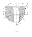
- Fig.1 is a perspective view of a cutting tool according to the present invention;
- Fig. 2 is a bottom perspective view of a cutting insert shown in Fig. 1;
- Fig. 3 is a partial exploded view of the cutting tool of Fig. 1 showing one of the cutting inserts removed from its pocket;
- Fig. 4 is a partial view of the cutting tool of Fig. 1 showing a top view of one of the cutting inserts retained in its pocket;
- Fig. 5 is the same view as Fig. 4 with the position of the cutting insert shown in dashed lines so that the insert pocket can be seen in a top view; and
- Fig. 6 is a cross-sectional view taken along line VI-VI in Fig. 4 with the retaining screw removed.
- Attention is drawn to the drawings. A
cutting tool 10 comprises atool body 12 having a plurality of mounting legs 14 formed at afront end 16 of thetool body 12. Each mounting leg 14 has aninsert pocket 18 in which acutting insert 20 is retained by means of aretaining screw 22. Thecutting tool 10 has arear end 23 opposite thefront end 16 with an axis of rotation A passing through the front andrear ends - The insert pocket comprises a
base wall 24 and asidewall 26 that is transversely directed to thebase wall 24. A generallycircular recess 28 extends downwardly from thebase wall 24. Therecess 28 has alower wall 30 bounded by aperipheral wall 32 extending uprightly from thelower wall 30 to thebase wall 24. Theperipheral wall 32 of therecess 28 preferably comprises two circular portions of differing radii, but having the same center. Theperipheral wall 32 comprises amajor portion 34 having a major radius R1, and aminor portion 36 having a minor radius R2. The minor radius R2 is smaller than the major radius R1. According to a specific application of the present invention, the minor radius R2 is 0.25 mm smaller than the major radius R1. The angular extent of theminor portion 36 is smaller than the angular extent of themajor portion 34. In accordance with a specific application, theminor portion 36 of theperipheral wall 32 has an angular extent ϕ of approximately 40°. A threaded bore 38, having a pocket axis C, for receiving the retainingscrew 22, extends downwardly from thelower wall 30 of therecess 28. The centers of the two circles on which the major andminor portions - The
sidewall 26 comprises three sidewall sections, two rear sidewall sections, a firstrear sidewall section 40 and a secondrear sidewall section 42 separated by a first recessedregion 44 and aside sidewall section 46. The firstrear sidewall section 40 is adjacent theside sidewall section 46 and separated from it by a second recessedregion 48. The firstrear sidewall section 40 has aregion 50 adjacent the first recessedregion 44, at least a portion of which constitutes afirst abutment surface 52 for abutting the cuttinginsert 20. Similarly, the secondrear sidewall section 42 has aregion 54 adjacent the first recessedregion 44, at least a portion of which constitutes asecond abutment surface 56 for abutting the cuttinginsert 20. Also, at least a portion of theminor portion 36 constitutes athird abutment surface 58 for abutting the cuttinginsert 20. As will be explained in greater detail below, the first, second and third abutment surfaces are designed to retain the cuttinginsert 20 in theinsert pocket 18 in a well defined and secure manner. - Attention is drawn to Fig. 5. It will be noted that the
minor portion 36, and therefore thethird abutment surface 58, is located adjacent theside sidewall 46 towards the front of theinsert pocket 18. In terms of an analog clock, the minor portion is located approximately between 7 and 8 O' clock. It will be appreciated that the precise location of theminor portion 36 is a question of design and distribution of forces. In practice, the illustrated location of theminor portion 36 is a preferred location. However, it can also be located at other locations between the preferred location up to approximately adjacent the second recessedregion 48. - The cutting
insert 20 comprises anupper surface 60, alower surface 62 and aside surface 64 that extends between the upper andlower surfaces upper surface 60 and theside surface 64 intersect at acutting edge 66 comprising three cutting edge portions 68 separated from each other by corner cutting edges 70. Each of the three cutting edge portions comprises a convexfirst cutting edge 72 that extends between a straightsecond cutting edge 74 and an adjacentcorner cutting edge 70. Theside surface 64 is divided into sections corresponding to the various cutting edges. Accordingly, theside surface 64 has a firstside surface section 76 adjacent thefirst cutting edge 72, a secondside surface section 78 adjacent thesecond cutting edge 74 and sidesurface corner section 80 adjacentcorner cutting edge 70. Acylindrical protrusion 82 having a cylindricalperipheral surface 84 extends downwardly from thelower surface 62 to abottom surface 86 of theprotrusion 82. Theperipheral surface 84 is perpendicular to thelower surface 62. A centrally located throughbore 88, having an insert axis B, extends between theupper surface 60 and thebottom surface 86. Theprotrusion 82 has a protrusion radius R3. The protrusion radius R3 is smaller than the major radius R1 and approximately equal to the minor radius R2. - The three cutting edge portions 68 are rotationally symmetrically arranged with respect to the insert axis B. The
first cutting edge 72 is substantially larger than thesecond cutting edge 74. According to a preferred embodiment of the present invention, thefirst cutting edge 72 subtends a first angle α of 70° at the insert axis B and thesecond cutting edge 74 subtends a second angle β of 35° at the insert axis B. The first and second cutting edges 72, 74 of a given cutting edge portion 68 make an obtuse interior third angle δ of 153° between each other. The cuttinginsert 20 is indexable and has three indexing positions. - In order to secure the cutting
insert 20 in theinsert pocket 18, theprotrusion 82 is inserted into therecess 28 until thelower surface 62 of the cutting insert abuts thebase wall 24 of the insert pocket, with a portion of a given sidesurface corner section 80 located in the first recessedregion 44. The retainingscrew 22 is then placed in the throughbore 88 of the cutting insert and threadingly engaged with the threaded bore 38 and tightened for securely retaining the cutting insert in theinsert pocket 18. When the cuttinginsert 20 is securely retained in theinsert pocket 18 the first and second abutment surfaces 52, 56 abut the first and secondside surface sections side surface corner 80, being common to the first and secondside surface sections third abutment surface 58 abuts the cylindricalperipheral surface 84 of theprotrusion 82 at a third support surface 58'. - The pocket axis C of the threaded bore 38 is slightly offset with respect to the insert axis B. This offset, i.e., eccentricity, is provided so that when the retaining
screw 22 is tightened, abutment forces are exerted by the abutment surfaces 52, 56, 58 on the cutting insert providing a pre-tensioning of the cuttinginsert 20 in order to obtain a well defined location of the cuttinginsert 20 in theinsert pocket 18. Since thethird abutment surface 58 lies on a surface which is concentric with the pocket axis C the abutment force applied by it on theprotrusion 82 of the cutting insert is directed towards the insert axis B and therefore cannot contribute to the rotation of the cutting insert about the insert axis B. The location and direction of each of the first and second abutment surfaces 52, 56 are designed so that the under working conditions net abutment force applied by these abutments surfaces to theside surface 64 of the insert does not give rise to rotation of the cutting insert about the insert axis B. In other words, the lines of action of the abutment forces of the first and second abutment surfaces 52, 56 operate in opposite senses about the insert axis B and cancel out. Hence, the present invention guarantees unique and stable location of the cuttinginsert 20 in theinsert pocket 18. - The cutting
tool 10 is particularly suitable for performing face milling by thefirst cutting edge 72 and ramp-down milling operations by thesecond cutting edge 74. Since thefirst cutting edge 72 is convex and has a relatively large radius of curvature, the cuttinginsert 20 can cut at a relatively high feed speed at a small depth of cut. The cutting forces acting on the cutting insert in such a case are directed substantially axially, therefore, it is possible to cut with a tool having a relatively long overhang without exceeding the allowed radial forces that tend to bend the tool and cause vibrations. - Although the present invention has been described to a certain degree of particularity, it should be understood that various alterations and modifications could be made without departing from the scope of the invention as hereinafter claimed.
Claims (18)
- A cutting tool (10), having a longitudinal axis (A), the cutting tool comprises a tool body (12), having at least one mounting leg (14) formed at a front end (16) thereof, the at least one mounting leg (14) having an insert pocket (18) with a cutting insert (20) retained therein;
the insert pocket comprises a base wall (24) and first and second rear sidewall sections (40, 42) transversely directed to the base wall (24), a generally circular recess (28) extends downwardly from the base wall (24), the recess has a lower wall (30) bounded by a peripheral wall (32) extending uprightly from the lower wall (30) to the base wall (24),
the cutting insert comprises an upper surface (60), a lower surface (62) and a side surface (64) extending therebetween, the upper and side surfaces (60, 64) intersecting at a cutting edge (66), a cylindrical protrusion (82) having a cylindrical peripheral surface (84) extends downwardly from the lower surface (62) to a bottom surface (86) of the protrusion (82);
wherein the cutting insert (20) is retained in the insert pocket (18) with first, second and third abutment surfaces (52, 56, 58) of the insert pocket (18) abutting the cutting insert (20), where the first abutment surface (52) is located on the first rear sidewall section (40) and it abuts a first support surface (52') located on the side surface (64) of the cutting insert, the second abutment surface (56) is located on the second rear sidewall section (42) and it abuts a second support surface (56') located on the side surface (64) of the cutting insert, and the third abutment surface (58) is located on the peripheral wall (32) of the recess (28) and it abuts a third support surface (58') located on the cylindrical peripheral surface (84) of the protrusion (82) of the cutting insert (20). - The cutting tool according to claim 1, wherein the cutting edge (66) comprises at least three cutting edge portions (68) that are separated from each other by corner cutting edges (70) and each cutting edge portion comprises a first cutting edge (72) that extends between a second cutting edge (74) and an adjacent corner cutting edge (70).
- The cutting tool according to claim 2, wherein the first cutting edge (72) is convex.
- The cutting tool according to claim 3, wherein the second cutting edge (74) is straight.
- The cutting tool according to claim 2, wherein the side surface (64) comprises side surface sections with a first side surface section (76) adjacent the first cutting edge (72), a second side surface section (78) adjacent the second cutting edge (74) and a side surface corner section (80) adjacent the corner cutting edge (70), each of the side surface sections extending from its associated cutting edge towards me lower surface (62).
- The cutting tool according to claim 5, wherein the first and second rear sidewall sections (40, 42) are separated by a first recessed region (44).
- The cutting tool according to claim 6, wherein the first support surface (52*) and the second support surface (56') are located on either side of a common side surface corner section (80).
- The cutting tool according to claim 7, wherein a portion of the common side surface corner section (80) is located in the first recessed region (44).
- The cutting tool according to claim 4, wherein the peripheral wall (32) of the recess (28) comprises a major portion (34) having a major radius R1, and a minor portion (36) having a minor radius R2.
- The cutting tool according to claim 9, wherein the minor radius R2 is smaller than the major radius R1.
- The cutting tool according to claim 10, wherein the angular extent of the minor portion (36) is smaller than the angular extent of the major portion (34).
- The cutting tool according to claim 11, wherein a threaded bore (38) extends downwardly from the lower wall (30) of the recess (28).
- The cutting tool according to claim 12, wherein a through bore (88), having an insert axis (B), extends between the upper surface (60) of the cutting insert (20) and the bottom surface (86) of the protrusion (82).
- The cutting tool according to claim 13, wherein a retaining screw (22) is located in the through bore (88) and threadingly engages the threaded bore (38).
- The cutting tool according to claim 13, wherein first cutting edge (72) subtends a first angle (α) of 70° with the insert axis (B).
- The cutting tool according to claim 15, wherein the second cutting edge (74) subtends a second angle (β) of 35° with the insert axis.
- The cutting tool according to claim 16, wherein the first catting edge (72) forms an obtuse interior third angle (γ) with the adjacent second cuffing edge (74).
- The cutting tool according to claim 17, wherein the third angle is 153°.
Priority Applications (1)
| Application Number | Priority Date | Filing Date | Title |
|---|---|---|---|
| EP06006268A EP1700656A3 (en) | 2001-10-16 | 2002-09-29 | Cutting tool and cutting insert therefor |
Applications Claiming Priority (5)
| Application Number | Priority Date | Filing Date | Title |
|---|---|---|---|
| IL14596501 | 2001-10-16 | ||
| IL14596501A IL145965A0 (en) | 2001-10-16 | 2001-10-16 | Cutting tool and a cutting insert therefor |
| IL15078302A IL150783A0 (en) | 2001-10-16 | 2002-07-17 | Cutting tool and cutting insert therefor |
| IL15078302 | 2002-07-17 | ||
| PCT/IL2002/000793 WO2003033195A1 (en) | 2001-10-16 | 2002-09-29 | Cutting tool and cutting insert therefor |
Related Child Applications (1)
| Application Number | Title | Priority Date | Filing Date |
|---|---|---|---|
| EP06006268A Division EP1700656A3 (en) | 2001-10-16 | 2002-09-29 | Cutting tool and cutting insert therefor |
Publications (2)
| Publication Number | Publication Date |
|---|---|
| EP1436110A1 EP1436110A1 (en) | 2004-07-14 |
| EP1436110B1 true EP1436110B1 (en) | 2006-11-29 |
Family
ID=26324048
Family Applications (2)
| Application Number | Title | Priority Date | Filing Date |
|---|---|---|---|
| EP02775176A Expired - Lifetime EP1436110B1 (en) | 2001-10-16 | 2002-09-29 | Cutting tool |
| EP06006268A Withdrawn EP1700656A3 (en) | 2001-10-16 | 2002-09-29 | Cutting tool and cutting insert therefor |
Family Applications After (1)
| Application Number | Title | Priority Date | Filing Date |
|---|---|---|---|
| EP06006268A Withdrawn EP1700656A3 (en) | 2001-10-16 | 2002-09-29 | Cutting tool and cutting insert therefor |
Country Status (22)
| Country | Link |
|---|---|
| US (1) | US6709205B2 (en) |
| EP (2) | EP1436110B1 (en) |
| JP (2) | JP4095026B2 (en) |
| KR (2) | KR20060115405A (en) |
| CN (1) | CN100402213C (en) |
| AT (1) | ATE346710T1 (en) |
| AU (1) | AU2002341360C1 (en) |
| BG (1) | BG65451B1 (en) |
| BR (1) | BR0213049B1 (en) |
| CA (1) | CA2461184C (en) |
| DE (1) | DE60216489T2 (en) |
| DK (1) | DK1436110T3 (en) |
| ES (1) | ES2272780T3 (en) |
| IL (1) | IL150783A0 (en) |
| MX (1) | MXPA04003471A (en) |
| NO (1) | NO20041851L (en) |
| NZ (1) | NZ531725A (en) |
| PL (1) | PL199817B1 (en) |
| PT (1) | PT1436110E (en) |
| RO (1) | RO122771B1 (en) |
| RU (1) | RU2304492C2 (en) |
| WO (1) | WO2003033195A1 (en) |
Families Citing this family (40)
| Publication number | Priority date | Publication date | Assignee | Title |
|---|---|---|---|---|
| US20040253063A1 (en) * | 2003-05-29 | 2004-12-16 | Arm Tooling, Inc. | Cutting tool insert and cutter body |
| DE102004006388A1 (en) * | 2004-02-09 | 2005-08-25 | Aleit Gmbh | Insert milling cutters |
| US20050271483A1 (en) * | 2004-06-02 | 2005-12-08 | Sandvik Ab | Indexable cutting inserts and methods for producing the same |
| DE202004010630U1 (en) | 2004-07-06 | 2005-11-17 | Kennametal Inc. | milling tool |
| US7789598B2 (en) * | 2005-07-12 | 2010-09-07 | Kyocera Corporation | Surface coated cutting tool |
| DE102005033920A1 (en) * | 2005-07-20 | 2007-01-25 | Kennametal Inc. | Cutting insert, tool and method for machining a workpiece |
| SE529068C2 (en) * | 2005-09-28 | 2007-04-24 | Seco Tools Ab | Milling inserts and milling tools |
| AT8743U1 (en) * | 2005-10-19 | 2006-12-15 | Ceratizit Austria Gmbh | MILLING TOOL |
| JP5076438B2 (en) * | 2006-01-30 | 2012-11-21 | 三菱マテリアル株式会社 | Insert-type cutting tool and method of fixing insert in insert-type cutting tool |
| US7510353B2 (en) * | 2006-02-16 | 2009-03-31 | Remark Technologies, Inc. | Indexable cutting tool insert and cutting tool |
| US8287213B2 (en) * | 2006-02-16 | 2012-10-16 | Remark Technologies, Inc. | Indexable cutting tool insert for cutting tools |
| US7429150B2 (en) * | 2006-05-31 | 2008-09-30 | Kennametal Inc. | Tool holder with spherical contact points |
| IL178813A (en) * | 2006-10-23 | 2010-06-30 | Iscar Ltd | Tangential cutting insert having a base protrusion seating arrangement |
| KR100886455B1 (en) * | 2006-12-27 | 2009-03-04 | 한국야금 주식회사 | Cutting insert for high-efficient cutting |
| SE530808C2 (en) * | 2007-01-31 | 2008-09-16 | Sandvik Intellectual Property | Tools for chip separating machining, as well as cutting and basic body for this |
| SE531502C2 (en) * | 2007-06-05 | 2009-04-28 | Sandvik Intellectual Property | Tools for chip separating machining as well as basic body and indexable cutting for this |
| DE102009035754A1 (en) * | 2009-07-24 | 2011-01-27 | Hartmetall-Werkzeugfabrik Paul Horn Gmbh | Cutting insert for a cutting tool for machining, in particular for high-feed milling |
| JP2011110664A (en) * | 2009-11-27 | 2011-06-09 | Sumitomo Electric Hardmetal Corp | Throwaway type cutting tool |
| DE102010000640A1 (en) * | 2010-03-04 | 2011-09-08 | Gühring Ohg | end mill |
| IL206272A (en) * | 2010-06-07 | 2014-08-31 | Iscar Ltd | Cutting insert and milling tool |
| IL208253A (en) * | 2010-09-19 | 2015-01-29 | Iscar Ltd | Milling cutter and cutting insert therefor |
| AT12672U1 (en) * | 2011-09-15 | 2012-09-15 | Ceratizit Luxembourg S Ar L | SET OF CUTTING INSERTS AND MILLING TOOL HOLDER |
| JP5853297B2 (en) | 2012-07-24 | 2016-02-09 | 住友電工ハードメタル株式会社 | Replaceable cutting tool |
| JP6194013B2 (en) * | 2013-11-19 | 2017-09-06 | 京セラ株式会社 | Cutting insert, cutting tool and method of manufacturing workpiece |
| US9481038B2 (en) * | 2013-12-11 | 2016-11-01 | Iscar, Ltd. | Cutting insert having a dovetail anti-slip arrangement |
| EP2883640B1 (en) * | 2013-12-13 | 2017-05-17 | Sandvik Intellectual Property AB | Cutting tool with abutment members and toolholder and cutting insert therefor |
| WO2015198812A1 (en) * | 2014-06-24 | 2015-12-30 | 住友電工ハードメタル株式会社 | Cutting tool and tool body |
| WO2016002863A1 (en) * | 2014-07-02 | 2016-01-07 | 株式会社タンガロイ | Cutting instrument body and blade-exchangeable cutting instrument |
| TWI494181B (en) * | 2014-07-28 | 2015-08-01 | Hsin Tien Chang | Discarded milling cutter structure |
| AT14369U1 (en) * | 2014-11-24 | 2015-09-15 | Ceratizit Austria Gmbh | Tool for machining |
| CN105081433A (en) * | 2015-09-14 | 2015-11-25 | 哈尔滨理工大学 | Special vertical staggered-tooth adjustable width cutting knife for disk milling slotting of open blisk |
| EP3144087A1 (en) * | 2015-09-18 | 2017-03-22 | Sandvik Intellectual Property AB | A cutting tool, a tool body and a method for producing a tool body |
| TWI825040B (en) * | 2017-11-30 | 2023-12-11 | 以色列商艾斯卡公司 | Single-sided three-way indexable milling insert, tool holder and insert mill comprising the insert and the tool holder |
| KR102011329B1 (en) | 2017-12-29 | 2019-08-14 | 한국야금 주식회사 | Cutting insert and cutting tool mounted with the same |
| JP6997341B2 (en) | 2018-04-23 | 2022-01-17 | カーボン,インコーポレイテッド | Resin extractor for additive manufacturing |
| WO2020069152A1 (en) | 2018-09-26 | 2020-04-02 | Carbon, Inc. | Spin cleaning method and apparatus for additive manufacturing |
| CN113272117B (en) | 2019-01-07 | 2024-08-02 | 卡本有限公司 | System and method for resin recovery in additive manufacturing |
| JP6861755B2 (en) * | 2019-04-26 | 2021-04-21 | 株式会社牧野フライス製作所 | How to machine milling tools and workpieces |
| US11440259B2 (en) | 2020-01-31 | 2022-09-13 | Carbon, Inc. | Resin reclamation centrifuge rotor for additively manufactured objects |
| EP4225560A1 (en) | 2020-10-09 | 2023-08-16 | Carbon, Inc. | Vapor spin cleaning of additively manufactured parts |
Family Cites Families (21)
| Publication number | Priority date | Publication date | Assignee | Title |
|---|---|---|---|---|
| DE680231C (en) * | 1937-02-26 | 1939-08-24 | Elek Sche Unternehmungen Akt G | Knife head with ring-shaped knives |
| LU37714A1 (en) * | 1958-11-19 | |||
| GB1020029A (en) * | 1962-04-24 | 1966-02-16 | Uddeholms Ab | Facing cutters |
| US3946475A (en) * | 1974-02-11 | 1976-03-30 | The Valeron Corporation | Cutting insert locking means |
| SE452271B (en) * | 1982-04-01 | 1987-11-23 | Sandvik Ab | CUTS AND TOOLS FOR SPANISH WORKING |
| JPH0135777Y2 (en) * | 1985-05-25 | 1989-11-01 | ||
| DE8800929U1 (en) * | 1988-01-27 | 1989-05-24 | Komet Stahlhalter- Und Werkzeugfabrik Robert Breuning Gmbh, 7122 Besigheim | Drilling tool for drilling in solid metal material, especially for drilling in plate stacks |
| US4930945A (en) * | 1988-05-20 | 1990-06-05 | Mitsubishi Metal Corporation | Insert rotary cutter |
| DE4430171C2 (en) * | 1994-08-25 | 1996-08-14 | Walter Ag | Form-locked insert |
| SE505511C2 (en) * | 1994-12-15 | 1997-09-08 | Sandvik Ab | Milling body and method of manufacture thereof |
| JPH0994705A (en) * | 1995-09-29 | 1997-04-08 | Bitsugu Alpha Kk | Cutting tool |
| DE69619545T2 (en) * | 1995-12-21 | 2002-10-10 | Sandvik Ab, Sandviken | TURNING CUTTING TOOLS |
| IL119841A (en) * | 1996-12-16 | 2000-02-29 | Iscar Ltd | Cutting inserts |
| JPH11197906A (en) * | 1998-01-09 | 1999-07-27 | Dijet Ind Co Ltd | Round shape throw-away tip or throw-away cutting tool |
| IL123685A (en) * | 1998-03-16 | 2001-09-13 | Iscar Ltd | Modular cutting tool assembly |
| JP3317490B2 (en) * | 1998-06-18 | 2002-08-26 | 日立ツール株式会社 | High feed indexable rotary tool |
| JP2000052111A (en) * | 1998-08-03 | 2000-02-22 | Mitsubishi Materials Corp | Throwaway tip holding mechanism for cutting tool |
| SE519123C2 (en) * | 1998-12-22 | 2003-01-14 | Seco Tools Ab | Cuts and tools for cutting machining and method of mounting cutters therein |
| JP3468141B2 (en) * | 1999-01-12 | 2003-11-17 | 三菱マテリアル株式会社 | Indexable insert and indexable drilling tool equipped with indexable insert |
| JP4540764B2 (en) * | 1999-04-27 | 2010-09-08 | 株式会社タンガロイ | Cutting tools |
| US6508612B1 (en) * | 2000-09-05 | 2003-01-21 | Kennametal Inc. | Milling cutter capable of using inserts of various geometrical shapes |
-
2002
- 2002-07-17 IL IL15078302A patent/IL150783A0/en active IP Right Grant
- 2002-09-29 CN CNB028203097A patent/CN100402213C/en not_active Expired - Lifetime
- 2002-09-29 WO PCT/IL2002/000793 patent/WO2003033195A1/en active Application Filing
- 2002-09-29 RO ROA200400316A patent/RO122771B1/en unknown
- 2002-09-29 BR BRPI0213049-1A patent/BR0213049B1/en not_active IP Right Cessation
- 2002-09-29 KR KR1020067022638A patent/KR20060115405A/en active IP Right Grant
- 2002-09-29 JP JP2003535974A patent/JP4095026B2/en not_active Expired - Lifetime
- 2002-09-29 NZ NZ531725A patent/NZ531725A/en not_active IP Right Cessation
- 2002-09-29 EP EP02775176A patent/EP1436110B1/en not_active Expired - Lifetime
- 2002-09-29 PL PL368240A patent/PL199817B1/en unknown
- 2002-09-29 KR KR1020047005497A patent/KR100670863B1/en active IP Right Grant
- 2002-09-29 PT PT02775176T patent/PT1436110E/en unknown
- 2002-09-29 DE DE60216489T patent/DE60216489T2/en not_active Expired - Lifetime
- 2002-09-29 EP EP06006268A patent/EP1700656A3/en not_active Withdrawn
- 2002-09-29 AT AT02775176T patent/ATE346710T1/en active
- 2002-09-29 ES ES02775176T patent/ES2272780T3/en not_active Expired - Lifetime
- 2002-09-29 MX MXPA04003471A patent/MXPA04003471A/en active IP Right Grant
- 2002-09-29 RU RU2004111599/02A patent/RU2304492C2/en active
- 2002-09-29 DK DK02775176T patent/DK1436110T3/en active
- 2002-09-29 CA CA002461184A patent/CA2461184C/en not_active Expired - Lifetime
- 2002-09-29 AU AU2002341360A patent/AU2002341360C1/en not_active Ceased
- 2002-10-16 US US10/270,509 patent/US6709205B2/en not_active Expired - Lifetime
-
2004
- 2004-04-13 BG BG108680A patent/BG65451B1/en unknown
- 2004-05-05 NO NO20041851A patent/NO20041851L/en not_active Application Discontinuation
-
2007
- 2007-08-27 JP JP2007220414A patent/JP2007301720A/en not_active Withdrawn
Also Published As
Similar Documents
| Publication | Publication Date | Title |
|---|---|---|
| EP1436110B1 (en) | Cutting tool | |
| AU2002341360A1 (en) | Cutting tool and cutting insert therefor | |
| KR101292441B1 (en) | Tangential cutting insert | |
| EP0585871B1 (en) | A cutting insert for a milling cutter | |
| US5738468A (en) | Shim for cutting tool with replaceable cutting insert | |
| EP1635977B1 (en) | A milling tool with co-operating projections and recessess between the cutting insert and the holder | |
| EP1401602B1 (en) | Cutting tool and cutting insert therefor | |
| EP2101947B1 (en) | Cutting insert and cutting tool | |
| EP2664399B1 (en) | Cutting tool | |
| CA2531425C (en) | Cutting insert | |
| EP2581157B1 (en) | Cutting tool for grooving and parting operations | |
| EP3924128B1 (en) | Rotary cutting body having insert pocket with seat surface provided with a plurality of abutment elements, rotary cutting tool and insert | |
| JP2002066811A (en) | Throwaway tip | |
| US6497537B1 (en) | Slotting cutter with cartridge assembly | |
| CA2394335A1 (en) | Slotting cutter | |
| JP3118956B2 (en) | Indexable tip | |
| ZA200402019B (en) | Cutting tool and cutting insert therefor. |
Legal Events
| Date | Code | Title | Description |
|---|---|---|---|
| PUAI | Public reference made under article 153(3) epc to a published international application that has entered the european phase |
Free format text: ORIGINAL CODE: 0009012 |
|
| 17P | Request for examination filed |
Effective date: 20040422 |
|
| AK | Designated contracting states |
Kind code of ref document: A1 Designated state(s): AT BE BG CH CY CZ DE DK EE ES FI FR GB GR IE IT LI LU MC NL PT SE SK TR |
|
| AX | Request for extension of the european patent |
Extension state: AL LT LV MK RO SI |
|
| GRAP | Despatch of communication of intention to grant a patent |
Free format text: ORIGINAL CODE: EPIDOSNIGR1 |
|
| RTI1 | Title (correction) |
Free format text: CUTTING TOOL |
|
| RAP1 | Party data changed (applicant data changed or rights of an application transferred) |
Owner name: NEW ISCAR LTD. |
|
| RAP1 | Party data changed (applicant data changed or rights of an application transferred) |
Owner name: ISCAR LTD. |
|
| GRAS | Grant fee paid |
Free format text: ORIGINAL CODE: EPIDOSNIGR3 |
|
| GRAA | (expected) grant |
Free format text: ORIGINAL CODE: 0009210 |
|
| AK | Designated contracting states |
Kind code of ref document: B1 Designated state(s): AT BE BG CH CY CZ DE DK EE ES FI FR GB GR IE IT LI LU MC NL PT SE SK TR |
|
| PG25 | Lapsed in a contracting state [announced via postgrant information from national office to epo] |
Ref country code: SK Free format text: LAPSE BECAUSE OF FAILURE TO SUBMIT A TRANSLATION OF THE DESCRIPTION OR TO PAY THE FEE WITHIN THE PRESCRIBED TIME-LIMIT Effective date: 20061129 |
|
| REG | Reference to a national code |
Ref country code: GB Ref legal event code: FG4D |
|
| REG | Reference to a national code |
Ref country code: CH Ref legal event code: NV Representative=s name: VOSSIUS & PARTNER Ref country code: CH Ref legal event code: EP |
|
| REG | Reference to a national code |
Ref country code: IE Ref legal event code: FG4D |
|
| REF | Corresponds to: |
Ref document number: 60216489 Country of ref document: DE Date of ref document: 20070111 Kind code of ref document: P |
|
| REG | Reference to a national code |
Ref country code: GB Ref legal event code: 732E |
|
| REG | Reference to a national code |
Ref country code: SE Ref legal event code: TRGR |
|
| PG25 | Lapsed in a contracting state [announced via postgrant information from national office to epo] |
Ref country code: BG Free format text: LAPSE BECAUSE OF FAILURE TO SUBMIT A TRANSLATION OF THE DESCRIPTION OR TO PAY THE FEE WITHIN THE PRESCRIBED TIME-LIMIT Effective date: 20070228 |
|
| REG | Reference to a national code |
Ref country code: PT Ref legal event code: SC4A Free format text: AVAILABILITY OF NATIONAL TRANSLATION Effective date: 20070118 |
|
| ET | Fr: translation filed | ||
| REG | Reference to a national code |
Ref country code: ES Ref legal event code: FG2A Ref document number: 2272780 Country of ref document: ES Kind code of ref document: T3 |
|
| PLBE | No opposition filed within time limit |
Free format text: ORIGINAL CODE: 0009261 |
|
| STAA | Information on the status of an ep patent application or granted ep patent |
Free format text: STATUS: NO OPPOSITION FILED WITHIN TIME LIMIT |
|
| 26N | No opposition filed |
Effective date: 20070830 |
|
| REG | Reference to a national code |
Ref country code: CH Ref legal event code: PCAR Free format text: VOSSIUS & PARTNER;NADELBERG 3;4051 BASEL (CH) |
|
| PG25 | Lapsed in a contracting state [announced via postgrant information from national office to epo] |
Ref country code: GR Free format text: LAPSE BECAUSE OF FAILURE TO SUBMIT A TRANSLATION OF THE DESCRIPTION OR TO PAY THE FEE WITHIN THE PRESCRIBED TIME-LIMIT Effective date: 20070301 Ref country code: MC Free format text: LAPSE BECAUSE OF NON-PAYMENT OF DUE FEES Effective date: 20070930 |
|
| PG25 | Lapsed in a contracting state [announced via postgrant information from national office to epo] |
Ref country code: IE Free format text: LAPSE BECAUSE OF NON-PAYMENT OF DUE FEES Effective date: 20071001 |
|
| PG25 | Lapsed in a contracting state [announced via postgrant information from national office to epo] |
Ref country code: EE Free format text: LAPSE BECAUSE OF FAILURE TO SUBMIT A TRANSLATION OF THE DESCRIPTION OR TO PAY THE FEE WITHIN THE PRESCRIBED TIME-LIMIT Effective date: 20061129 |
|
| PG25 | Lapsed in a contracting state [announced via postgrant information from national office to epo] |
Ref country code: LU Free format text: LAPSE BECAUSE OF NON-PAYMENT OF DUE FEES Effective date: 20070929 Ref country code: CY Free format text: LAPSE BECAUSE OF FAILURE TO SUBMIT A TRANSLATION OF THE DESCRIPTION OR TO PAY THE FEE WITHIN THE PRESCRIBED TIME-LIMIT Effective date: 20061129 |
|
| PGFP | Annual fee paid to national office [announced via postgrant information from national office to epo] |
Ref country code: DK Payment date: 20090715 Year of fee payment: 8 |
|
| PGFP | Annual fee paid to national office [announced via postgrant information from national office to epo] |
Ref country code: CH Payment date: 20090730 Year of fee payment: 8 Ref country code: FI Payment date: 20090922 Year of fee payment: 8 Ref country code: NL Payment date: 20090714 Year of fee payment: 8 |
|
| PGFP | Annual fee paid to national office [announced via postgrant information from national office to epo] |
Ref country code: BE Payment date: 20090714 Year of fee payment: 8 |
|
| BERE | Be: lapsed |
Owner name: ISCAR LTD. Effective date: 20100930 |
|
| PG25 | Lapsed in a contracting state [announced via postgrant information from national office to epo] |
Ref country code: IT Free format text: LAPSE BECAUSE OF NON-PAYMENT OF DUE FEES Effective date: 20090929 |
|
| REG | Reference to a national code |
Ref country code: NL Ref legal event code: V1 Effective date: 20110401 |
|
| REG | Reference to a national code |
Ref country code: CH Ref legal event code: PL |
|
| REG | Reference to a national code |
Ref country code: DK Ref legal event code: EBP |
|
| PG25 | Lapsed in a contracting state [announced via postgrant information from national office to epo] |
Ref country code: FI Free format text: LAPSE BECAUSE OF NON-PAYMENT OF DUE FEES Effective date: 20100929 |
|
| PG25 | Lapsed in a contracting state [announced via postgrant information from national office to epo] |
Ref country code: LI Free format text: LAPSE BECAUSE OF NON-PAYMENT OF DUE FEES Effective date: 20100930 Ref country code: BE Free format text: LAPSE BECAUSE OF NON-PAYMENT OF DUE FEES Effective date: 20100930 Ref country code: CH Free format text: LAPSE BECAUSE OF NON-PAYMENT OF DUE FEES Effective date: 20100930 |
|
| PGRI | Patent reinstated in contracting state [announced from national office to epo] |
Ref country code: IT Effective date: 20110616 |
|
| PG25 | Lapsed in a contracting state [announced via postgrant information from national office to epo] |
Ref country code: NL Free format text: LAPSE BECAUSE OF NON-PAYMENT OF DUE FEES Effective date: 20110401 |
|
| PG25 | Lapsed in a contracting state [announced via postgrant information from national office to epo] |
Ref country code: DK Free format text: LAPSE BECAUSE OF NON-PAYMENT OF DUE FEES Effective date: 20100930 |
|
| REG | Reference to a national code |
Ref country code: FR Ref legal event code: PLFP Year of fee payment: 15 |
|
| REG | Reference to a national code |
Ref country code: FR Ref legal event code: PLFP Year of fee payment: 16 |
|
| REG | Reference to a national code |
Ref country code: FR Ref legal event code: PLFP Year of fee payment: 17 |
|
| PGFP | Annual fee paid to national office [announced via postgrant information from national office to epo] |
Ref country code: ES Payment date: 20201117 Year of fee payment: 19 |
|
| PGFP | Annual fee paid to national office [announced via postgrant information from national office to epo] |
Ref country code: IT Payment date: 20210721 Year of fee payment: 20 Ref country code: AT Payment date: 20210813 Year of fee payment: 20 Ref country code: CZ Payment date: 20210817 Year of fee payment: 20 Ref country code: FR Payment date: 20210809 Year of fee payment: 20 |
|
| PGFP | Annual fee paid to national office [announced via postgrant information from national office to epo] |
Ref country code: DE Payment date: 20210813 Year of fee payment: 20 Ref country code: SE Payment date: 20210816 Year of fee payment: 20 Ref country code: TR Payment date: 20210728 Year of fee payment: 20 Ref country code: GB Payment date: 20210810 Year of fee payment: 20 |
|
| PGFP | Annual fee paid to national office [announced via postgrant information from national office to epo] |
Ref country code: PT Payment date: 20210720 Year of fee payment: 20 |
|
| REG | Reference to a national code |
Ref country code: DE Ref legal event code: R071 Ref document number: 60216489 Country of ref document: DE |
|
| REG | Reference to a national code |
Ref country code: GB Ref legal event code: PE20 Expiry date: 20220928 |
|
| PG25 | Lapsed in a contracting state [announced via postgrant information from national office to epo] |
Ref country code: GB Free format text: LAPSE BECAUSE OF EXPIRATION OF PROTECTION Effective date: 20220928 Ref country code: CZ Free format text: LAPSE BECAUSE OF EXPIRATION OF PROTECTION Effective date: 20220929 |
|
| REG | Reference to a national code |
Ref country code: ES Ref legal event code: FD2A Effective date: 20221031 |
|
| REG | Reference to a national code |
Ref country code: AT Ref legal event code: MK07 Ref document number: 346710 Country of ref document: AT Kind code of ref document: T Effective date: 20220929 |
|
| PG25 | Lapsed in a contracting state [announced via postgrant information from national office to epo] |
Ref country code: PT Free format text: LAPSE BECAUSE OF EXPIRATION OF PROTECTION Effective date: 20221011 Ref country code: ES Free format text: LAPSE BECAUSE OF NON-PAYMENT OF DUE FEES Effective date: 20210930 |