EP1434024A1 - Dispositif tractable de déminage en surface et de marquage de l'itinéraire déminé - Google Patents
Dispositif tractable de déminage en surface et de marquage de l'itinéraire déminé Download PDFInfo
- Publication number
- EP1434024A1 EP1434024A1 EP03293093A EP03293093A EP1434024A1 EP 1434024 A1 EP1434024 A1 EP 1434024A1 EP 03293093 A EP03293093 A EP 03293093A EP 03293093 A EP03293093 A EP 03293093A EP 1434024 A1 EP1434024 A1 EP 1434024A1
- Authority
- EP
- European Patent Office
- Prior art keywords
- plow
- vehicle
- demining
- wideners
- demining device
- Prior art date
- Legal status (The legal status is an assumption and is not a legal conclusion. Google has not performed a legal analysis and makes no representation as to the accuracy of the status listed.)
- Granted
Links
- 238000001514 detection method Methods 0.000 description 2
- 230000007257 malfunction Effects 0.000 description 2
- 239000004606 Fillers/Extenders Substances 0.000 description 1
- 230000004888 barrier function Effects 0.000 description 1
- 238000004880 explosion Methods 0.000 description 1
- 230000002093 peripheral effect Effects 0.000 description 1
- 238000005096 rolling process Methods 0.000 description 1
- 230000001960 triggered effect Effects 0.000 description 1
Images


Classifications
-
- F—MECHANICAL ENGINEERING; LIGHTING; HEATING; WEAPONS; BLASTING
- F41—WEAPONS
- F41H—ARMOUR; ARMOURED TURRETS; ARMOURED OR ARMED VEHICLES; MEANS OF ATTACK OR DEFENCE, e.g. CAMOUFLAGE, IN GENERAL
- F41H11/00—Defence installations; Defence devices
- F41H11/12—Means for clearing land minefields; Systems specially adapted for detection of landmines
- F41H11/16—Self-propelled mine-clearing vehicles; Mine-clearing devices attachable to vehicles
- F41H11/20—Self-propelled mine-clearing vehicles; Mine-clearing devices attachable to vehicles with ground-penetrating elements, e.g. with means for removing buried landmines from the soil
- F41H11/24—Self-propelled mine-clearing vehicles; Mine-clearing devices attachable to vehicles with ground-penetrating elements, e.g. with means for removing buried landmines from the soil the elements being ploughs
-
- F—MECHANICAL ENGINEERING; LIGHTING; HEATING; WEAPONS; BLASTING
- F41—WEAPONS
- F41H—ARMOUR; ARMOURED TURRETS; ARMOURED OR ARMED VEHICLES; MEANS OF ATTACK OR DEFENCE, e.g. CAMOUFLAGE, IN GENERAL
- F41H11/00—Defence installations; Defence devices
- F41H11/12—Means for clearing land minefields; Systems specially adapted for detection of landmines
- F41H11/16—Self-propelled mine-clearing vehicles; Mine-clearing devices attachable to vehicles
- F41H11/28—Self-propelled mine-clearing vehicles; Mine-clearing devices attachable to vehicles using brushing or sweeping means or dozers to push mines lying on a surface aside; using means for removing mines intact from a surface
-
- F—MECHANICAL ENGINEERING; LIGHTING; HEATING; WEAPONS; BLASTING
- F41—WEAPONS
- F41H—ARMOUR; ARMOURED TURRETS; ARMOURED OR ARMED VEHICLES; MEANS OF ATTACK OR DEFENCE, e.g. CAMOUFLAGE, IN GENERAL
- F41H11/00—Defence installations; Defence devices
- F41H11/12—Means for clearing land minefields; Systems specially adapted for detection of landmines
- F41H11/16—Self-propelled mine-clearing vehicles; Mine-clearing devices attachable to vehicles
- F41H11/32—Decoy or sacrificial vehicles; Decoy or sacrificial devices attachable to vehicles
Definitions
- the technical sector of the present invention is that land clearance devices and more particularly demining plows.
- mine clearance plows surface is carried out by maintaining a plow flush with the ground by a hydraulic interface carried by a vehicle like a tractor or an armored vehicle.
- the mass of the plow and its supporting elements is carried by the part front of the vehicle, which significantly degrades its maneuverability.
- the object of the present invention is to provide a quick, mobile, easily manageable demining device, space-saving, easily transportable and whose implementation work is quick and easy.
- the invention therefore relates to a demining device intended to equip a civil or military vehicle, composed at least one chassis, a plow and a train rolling.
- the device has foldable or removable wideners, arranged at the ends of the plow.
- the expanders are connected to the plow by a pivot type connection and in this that they can be placed and held in two positions: a first position in which they are folded in relation to the plow, and a second position, in which they extend the plow.
- the expanders are independent elements that can be attached to the plow so as to extend it.
- the expanders are of sufficient size so that the total width of the plow and its extenders extending it either larger than the vehicle size.
- the device comprises several magnetic coils likely to create a magnetic field.
- the device comprises a physical marking system for the demined route.
- the marking system is removable and / or retractable.
- the device comprises a tow bar allowing the device to be towed by a vehicle.
- the device comprises an order management box comprising a link with the vehicle to allow the exchange of data, orders, and / or signals with the vehicle.
- the box has a energy generation and / or storage system
- a very first advantage of the device according to the invention resides in its great maneuverability by the vehicle fitted with it.
- Another advantage of the device lies in its capacity to equip both military vehicles and civil vehicles, such as an agricultural tractor, a clearing or a public works machine.
- Another advantage is that the vehicle equipped with this device is not subject to constraints, especially those related to the cantilever position of a heavy load, usually encountered on this type of device.
- Another advantage of the device lies in its compactness when in transport configuration, this which allows it to be hitched and towed by a vehicle conforms to the size of the roads.
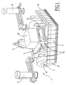
- FIG. 1 is a perspective view which represents a demining device 1 according to the invention, in its working configuration.
- the demining device 1 consists of a chassis 4, a plow 5, an undercarriage 7 comprising wheels 8 and an axle (not visible in the figure), a bar 9 for towing, a box 10 for order management and energy management, markers 11, expanders 12 of plow, magnetic coils of decoy 13 and a means (not shown) of communication between the vehicle and the box 10.
- the elements of the device are deployed to be used for detect, trigger and push off the route clearing ammunition (mines, grenades) placed in area.
- the plow 5 is arranged at ground level.
- the wideners 12 are placed in the extension of the plow 5, so that the width of the assembly plow / wideners is more important than the width of the vehicle fitted with the device.
- Tow bar 9 is raised so as not to hinder the fixing of the device 1 on the vehicle.
- the magnetic coils 13 arranged so as to create a magnetic field, covering at least the clearance width, so as to trigger mines at magnetic igniters located in the path of the vehicle.
- the operation of the demining coils is known and is widely described in other documents. We may in particular refer to patents FR-2 750 204 and FR-2 701 105 which describe such types of coils.
- the markers 11 are spaced apart by a substantially equal width to the width of the plow / spreader assembly, so to mark out the route taken by the vehicle of demining.
- the order management box 10 allows communicate with the driver of the vehicle and execute commands (for example by changing the magnetic field created by the coils 13) or transmit data (mine detection, malfunctions, detection barriers ).
- Box 10 is also equipped with a energy management system that powers the electrical, electromechanical or electronic systems of the device. This energy management system can be by example an electric battery or a dynamo.
- Figure 2 illustrates the use of the device 1 to using a vehicle 2.
- Vehicle 2 is preferably a vehicle fitted with a lifting arm mechanism 15, the device connects for example in place of a clearing blade, shovel or fork.
- the device 1 can also equip a vehicle without of such a mechanism 15. It will be just as effective but the vehicle mobility will be slightly affected.
- the vehicle 2 can for example be a military vehicle armored vehicle, an earthmoving vehicle or a machine agricultural.
- the device 1 is used here in its configuration of work. It is fixed on the lifting arms 15 (or, at lifting system fault, directly on the chassis vehicle 2) and is connected to vehicle 2 via the interface communication (not shown).
- FIGS 4 and 5 show, the demining according to the invention, in transport configuration.
- the markers 11 are folded against the box 10.
- the wideners 12 are also folded. We have shown here collapsible wideners, but these can also be removable for example with a tenon / mortise connection.
- the device is thus made more compact and can be towed, via its tow bar 9, by any vehicle fitted with a conventional means of fixing a tow bar.
- the device 1 When the device 1 is towed at the rear of the vehicle 2, it is inclined in order to raise the plow 5 by one sufficient height to allow towing of the device over long distances and at the required speed on the routes taken.
- FIG. 6 represents, in top view, a vehicle 2 equipped with a demining device in working position at the front and a demining device in configuration of rear transport.
- markers 11 and plow wideners 12 define a width L sufficient for the vehicle 2, of gauge G is not likely to roll over a mine.
- markers 11 and wideners 12 are folded back the width 1 of the demining device is less or equal to the gauge G of the vehicle in order to be towed on conventional transport routes.
- peripherals connected to the box 10 for order management.
- These devices can for example be sensors of position of elements, malfunction sensors, obstacle sensors, a positioning system (GPS), a sighting system, or any other device useful during a demining action.
- GPS positioning system
- sighting system or any other device useful during a demining action.
- chassis 4 The elements have been represented here in direct connection with chassis 4, but we can also imagine that they are powered by motors allowing their deployment or that they are supported by means depreciation intended to amortize accidents land and / or energy due to a mine explosion.
Landscapes
- Engineering & Computer Science (AREA)
- General Engineering & Computer Science (AREA)
- Life Sciences & Earth Sciences (AREA)
- Soil Sciences (AREA)
- Control Of Position, Course, Altitude, Or Attitude Of Moving Bodies (AREA)
- Harvester Elements (AREA)
- Road Signs Or Road Markings (AREA)
- Control And Other Processes For Unpacking Of Materials (AREA)
- Geophysics And Detection Of Objects (AREA)
- Aiming, Guidance, Guns With A Light Source, Armor, Camouflage, And Targets (AREA)
Abstract
Description
- la figure 1 représente une vue générale d'un dispositif de déminage selon l'invention en configuration de travail,
- la figure 2 représente, en vue de profil, un véhicule équipé d'un dispositif de déminage selon l'invention en position de travail,
- la figure 3 représente, en vue de profil, un véhicule équipé d'un dispositif de déminage selon l'invention en position de franchissement d'obstacle,
- la figure 4 représente, en vue de profil, un véhicule équipé d'un dispositif de déminage selon l'invention, en position de transport,
- la figure 5 représente une vue générale d'un dispositif de déminage selon l'invention en configuration de transport, et
- la figure 6 représente en vue de dessus un véhicule équipé d'un dispositif de déminage selon l'invention, en position de travail à l'avant et d'un dispositif de déminage en configuration de transport à l'arrière.
Claims (10)
- Dispositif (1) de déminage destiné à équiper un véhicule (2) civil ou militaire, composé d'au moins un châssis (4), d'une charrue (5) et d'un train de roulement (7), caractérisé en ce qu'il comporte des élargisseurs (12) repliables ou amovibles disposés aux extrémités de la charrue (5).
- Dispositif de déminage selon la revendication 1, caractérisé en ce que les élargisseurs (12) sont reliés à la charrue (5) par une liaison de type pivot et en ce qu'ils peuvent être placés et maintenus dans deux positions distinctes ,une première position dans laquelle ils sont repliés par rapport à la charrue, et une deuxième position dans laquelle ils prolongent la charrue.
- Dispositif de déminage selon la revendication 1, caractérisé en ce que les élargisseurs (12) sont des éléments indépendants pouvant être fixés à la charrue (5) de manière à prolonger celle-ci.
- Dispositif de déminage selon la revendication 2 ou 3, caractérisé en ce que les élargisseurs (12) sont de dimension suffisante pour que la largeur totale (L) de la charrue et de ses élargisseurs (12) la prolongeant soit supérieure au gabarit (G) du véhicule.
- Dispositif de déminage selon la revendication 4, caractérisé en ce qu'il comporte plusieurs bobines magnétiques (13) susceptibles de créer un champ magnétique.
- Dispositif de déminage selon l'une quelconque des revendications précédentes, caractérisé en ce qu'il comporte un système (11) de marquage physique de l'itinéraire déminé.
- Dispositif de selon la revendication 6, caractérisé en ce que le système (11) de marquage est amovible et/ou rétractable.
- Dispositif de déminage selon l'une quelconque des revendications précédentes, caractérisé en ce qu'il comporte une barre de remorquage (9) permettant au dispositif d'être tracté par un véhicule.
- Dispositif de déminage selon l'une des revendications précédentes, caractérisé en ce qu'il comporte une boíte (10) de gestion de commande comportant une liaison avec le véhicule (2) afin de permettre l'échange de données, d'ordres, et/ou de signaux avec le véhicule (2).
- Dispositif de déminage selon la revendication 9, caractérisé en ce que la boíte (10) comporte un système de génération et/ou de stockage d'énergie.
Applications Claiming Priority (2)
| Application Number | Priority Date | Filing Date | Title |
|---|---|---|---|
| FR0216094 | 2002-12-18 | ||
| FR0216094A FR2849178B1 (fr) | 2002-12-18 | 2002-12-18 | Dispositif tractable de deminage en surface et de marquage de l'itineraire demine |
Publications (2)
| Publication Number | Publication Date |
|---|---|
| EP1434024A1 true EP1434024A1 (fr) | 2004-06-30 |
| EP1434024B1 EP1434024B1 (fr) | 2008-11-26 |
Family
ID=32406158
Family Applications (1)
| Application Number | Title | Priority Date | Filing Date |
|---|---|---|---|
| EP03293093A Expired - Lifetime EP1434024B1 (fr) | 2002-12-18 | 2003-12-10 | Dispositif tractable de déminage en surface et de marquage de l'itinéraire déminé |
Country Status (4)
| Country | Link |
|---|---|
| EP (1) | EP1434024B1 (fr) |
| AT (1) | ATE415609T1 (fr) |
| DE (1) | DE60324886D1 (fr) |
| FR (1) | FR2849178B1 (fr) |
Cited By (3)
| Publication number | Priority date | Publication date | Assignee | Title |
|---|---|---|---|---|
| EP2048469A1 (fr) | 2007-10-08 | 2009-04-15 | NEXTER Systems | Dispositif de déminage pour véhicule civil ou militaire |
| WO2010106281A1 (fr) * | 2009-03-19 | 2010-09-23 | Mbda France | Unité motorisée de déminage et de sécurisation d'un itinéraire à risques |
| GB2545638B (en) * | 2015-12-13 | 2021-07-21 | Pearson Eng Ltd | Improvements in or relating to mine ploughing |
Families Citing this family (3)
| Publication number | Priority date | Publication date | Assignee | Title |
|---|---|---|---|---|
| US8240239B1 (en) * | 2011-07-16 | 2012-08-14 | Kevin Mark Diaz | Green energy mine defeat system |
| JP5377618B2 (ja) * | 2011-12-08 | 2013-12-25 | 清 雨宮 | 地雷や不発弾の処理装置 |
| RU2639837C2 (ru) * | 2015-07-15 | 2017-12-22 | Федеральное Государственное Казённое Военное Образовательное Учреждение Высшего Профессионального Образования "Военный Учебно-Научный Центр Сухопутных Войск "Общевойсковая Академия Вооруженных Сил Российской Федерации" | Способ траления мин и устройство для его осуществления |
Citations (4)
| Publication number | Priority date | Publication date | Assignee | Title |
|---|---|---|---|---|
| FR2554575A1 (fr) * | 1983-11-05 | 1985-05-10 | Mak Maschinenbau Krupp | Dispositif de deminage pour mines terrestres |
| GB2155866A (en) * | 1984-03-21 | 1985-10-02 | Thyssen Ag | Apparatus for clearing light land mines |
| EP0326368A2 (fr) * | 1988-01-28 | 1989-08-02 | Firth Defence Systems Limited | Appareil de déminage |
| FR2701105A1 (fr) * | 1993-02-01 | 1994-08-05 | Giat Ind Sa | Dispositif de déminage. |
Family Cites Families (1)
| Publication number | Priority date | Publication date | Assignee | Title |
|---|---|---|---|---|
| FR2750204B1 (fr) | 1996-06-19 | 1998-08-07 | Giat Ind Sa | Bobine de deminage et dispositif de deminage en faisant application |
-
2002
- 2002-12-18 FR FR0216094A patent/FR2849178B1/fr not_active Expired - Fee Related
-
2003
- 2003-12-10 AT AT03293093T patent/ATE415609T1/de not_active IP Right Cessation
- 2003-12-10 DE DE60324886T patent/DE60324886D1/de not_active Expired - Lifetime
- 2003-12-10 EP EP03293093A patent/EP1434024B1/fr not_active Expired - Lifetime
Patent Citations (4)
| Publication number | Priority date | Publication date | Assignee | Title |
|---|---|---|---|---|
| FR2554575A1 (fr) * | 1983-11-05 | 1985-05-10 | Mak Maschinenbau Krupp | Dispositif de deminage pour mines terrestres |
| GB2155866A (en) * | 1984-03-21 | 1985-10-02 | Thyssen Ag | Apparatus for clearing light land mines |
| EP0326368A2 (fr) * | 1988-01-28 | 1989-08-02 | Firth Defence Systems Limited | Appareil de déminage |
| FR2701105A1 (fr) * | 1993-02-01 | 1994-08-05 | Giat Ind Sa | Dispositif de déminage. |
Cited By (6)
| Publication number | Priority date | Publication date | Assignee | Title |
|---|---|---|---|---|
| EP2048469A1 (fr) | 2007-10-08 | 2009-04-15 | NEXTER Systems | Dispositif de déminage pour véhicule civil ou militaire |
| WO2010106281A1 (fr) * | 2009-03-19 | 2010-09-23 | Mbda France | Unité motorisée de déminage et de sécurisation d'un itinéraire à risques |
| FR2943411A1 (fr) * | 2009-03-19 | 2010-09-24 | Mbda France | Unite motorisee de deminage et de securisation d'un itineraire a risques. |
| EP2233878A1 (fr) * | 2009-03-19 | 2010-09-29 | MBDA France | Unité motorisée de déminage et de sécurisation d'un itinéraire à risques |
| US8677875B2 (en) | 2009-03-19 | 2014-03-25 | Mbda France | Motor-driven unit for clearing mines from and securing a hazardous route |
| GB2545638B (en) * | 2015-12-13 | 2021-07-21 | Pearson Eng Ltd | Improvements in or relating to mine ploughing |
Also Published As
| Publication number | Publication date |
|---|---|
| FR2849178B1 (fr) | 2007-04-27 |
| ATE415609T1 (de) | 2008-12-15 |
| DE60324886D1 (de) | 2009-01-08 |
| FR2849178A1 (fr) | 2004-06-25 |
| EP1434024B1 (fr) | 2008-11-26 |
Similar Documents
| Publication | Publication Date | Title |
|---|---|---|
| US6044921A (en) | Earth-based vehicle | |
| CA2879172C (fr) | Essieu et vehicule comprenant au moins un tel essieu | |
| EP2485935A1 (fr) | Dispositif de protection contre les chocs d'un organe de vehicule automobile monte sous caisse | |
| EP1434024B1 (fr) | Dispositif tractable de déminage en surface et de marquage de l'itinéraire déminé | |
| FR3006958A1 (fr) | Engin de transport de charge pour milieu accidente | |
| EP2048469B1 (fr) | Dispositif de déminage pour véhicule civil ou militaire | |
| FR2568844A1 (fr) | Vehicule equipe d'un systeme de direction a quatre roues directrices | |
| FR3039104A1 (fr) | Vehicule automatique guide pour le deplacement multidirectionnel de charges | |
| CA1133109A (fr) | Dispositif mobile pour engendrer dans le sol des ondes acoustiques transversales | |
| EP3065954B1 (fr) | Robot terrestre de transport modulaire, procédé de montage et utilisation | |
| EP3698612A1 (fr) | Charrue avec un dispositif de compensation de l'effort latéral en cours de labour | |
| EP2233878B1 (fr) | Unité motorisée de déminage et de sécurisation d'un itinéraire à risques | |
| EP1004845A1 (fr) | Procédé et installation pour le déplacement précis d'un véhicule sur un terrain en particulier un véhicule de déminage | |
| FR2788404A1 (fr) | Vehicule de transport d'une personne dans des cultures disposees en rangees telles que la vigne | |
| FR2706371A1 (fr) | Engin de génie civil à haute vitesse. | |
| EP1531203A1 (fr) | Lame de déneigement, en V fixe, ouvert vers l'avant, orientable par un système hydraulique ou par un dispositif mécanique | |
| EP1793196B1 (fr) | Dispositif de déclenchement de mines | |
| WO2024133155A1 (fr) | Dispositif apte à se déplacer sur des terrains difficiles, tels qu'un champ de mines, ou sur des terrains sensibles, tels que des champs agricoles | |
| EP3715227B1 (fr) | Remorque et ensemble roulant comportant une telle remorque | |
| FR2805764A1 (fr) | Vehicule d'epandage a epandage variable | |
| FR2722143A1 (fr) | Dispositif de jumelage d'un jeu de roues | |
| EP4242020A1 (fr) | Engin motorisé présentant un système de suspension intégré à une roue | |
| FR2701805A1 (fr) | Enfouisseur d'engrais liquides tels que du lisier. | |
| FR2694998A1 (fr) | Enfouisseur d'engrais liquide tels que du lisier. | |
| EP1516966A1 (fr) | Vehicule militaire d'aménagement de terrain |
Legal Events
| Date | Code | Title | Description |
|---|---|---|---|
| PUAI | Public reference made under article 153(3) epc to a published international application that has entered the european phase |
Free format text: ORIGINAL CODE: 0009012 |
|
| AK | Designated contracting states |
Kind code of ref document: A1 Designated state(s): AT BE BG CH CY CZ DE DK EE ES FI FR GB GR HU IE IT LI LU MC NL PT RO SE SI SK TR |
|
| AX | Request for extension of the european patent |
Extension state: AL LT LV MK |
|
| 17P | Request for examination filed |
Effective date: 20040715 |
|
| AKX | Designation fees paid |
Designated state(s): AT BE BG CH CY CZ DE DK EE ES FI FR GB GR HU IE IT LI LU MC NL PT RO SE SI SK TR |
|
| RAP1 | Party data changed (applicant data changed or rights of an application transferred) |
Owner name: NEXTER SYSTEMS |
|
| GRAP | Despatch of communication of intention to grant a patent |
Free format text: ORIGINAL CODE: EPIDOSNIGR1 |
|
| GRAS | Grant fee paid |
Free format text: ORIGINAL CODE: EPIDOSNIGR3 |
|
| GRAA | (expected) grant |
Free format text: ORIGINAL CODE: 0009210 |
|
| AK | Designated contracting states |
Kind code of ref document: B1 Designated state(s): AT BE BG CH CY CZ DE DK EE ES FI FR GB GR HU IE IT LI LU MC NL PT RO SE SI SK TR |
|
| REG | Reference to a national code |
Ref country code: GB Ref legal event code: FG4D Free format text: NOT ENGLISH |
|
| REG | Reference to a national code |
Ref country code: CH Ref legal event code: EP |
|
| REG | Reference to a national code |
Ref country code: IE Ref legal event code: FG4D Free format text: LANGUAGE OF EP DOCUMENT: FRENCH |
|
| REF | Corresponds to: |
Ref document number: 60324886 Country of ref document: DE Date of ref document: 20090108 Kind code of ref document: P |
|
| PG25 | Lapsed in a contracting state [announced via postgrant information from national office to epo] |
Ref country code: ES Free format text: LAPSE BECAUSE OF FAILURE TO SUBMIT A TRANSLATION OF THE DESCRIPTION OR TO PAY THE FEE WITHIN THE PRESCRIBED TIME-LIMIT Effective date: 20090308 Ref country code: AT Free format text: LAPSE BECAUSE OF FAILURE TO SUBMIT A TRANSLATION OF THE DESCRIPTION OR TO PAY THE FEE WITHIN THE PRESCRIBED TIME-LIMIT Effective date: 20081126 |
|
| NLV1 | Nl: lapsed or annulled due to failure to fulfill the requirements of art. 29p and 29m of the patents act | ||
| PG25 | Lapsed in a contracting state [announced via postgrant information from national office to epo] |
Ref country code: SI Free format text: LAPSE BECAUSE OF FAILURE TO SUBMIT A TRANSLATION OF THE DESCRIPTION OR TO PAY THE FEE WITHIN THE PRESCRIBED TIME-LIMIT Effective date: 20081126 Ref country code: FI Free format text: LAPSE BECAUSE OF FAILURE TO SUBMIT A TRANSLATION OF THE DESCRIPTION OR TO PAY THE FEE WITHIN THE PRESCRIBED TIME-LIMIT Effective date: 20081126 Ref country code: NL Free format text: LAPSE BECAUSE OF FAILURE TO SUBMIT A TRANSLATION OF THE DESCRIPTION OR TO PAY THE FEE WITHIN THE PRESCRIBED TIME-LIMIT Effective date: 20081126 |
|
| BERE | Be: lapsed |
Owner name: NEXTER SYSTEMS Effective date: 20081231 |
|
| REG | Reference to a national code |
Ref country code: IE Ref legal event code: FD4D |
|
| PG25 | Lapsed in a contracting state [announced via postgrant information from national office to epo] |
Ref country code: RO Free format text: LAPSE BECAUSE OF FAILURE TO SUBMIT A TRANSLATION OF THE DESCRIPTION OR TO PAY THE FEE WITHIN THE PRESCRIBED TIME-LIMIT Effective date: 20081126 Ref country code: MC Free format text: LAPSE BECAUSE OF NON-PAYMENT OF DUE FEES Effective date: 20081231 Ref country code: IE Free format text: LAPSE BECAUSE OF FAILURE TO SUBMIT A TRANSLATION OF THE DESCRIPTION OR TO PAY THE FEE WITHIN THE PRESCRIBED TIME-LIMIT Effective date: 20081126 Ref country code: EE Free format text: LAPSE BECAUSE OF FAILURE TO SUBMIT A TRANSLATION OF THE DESCRIPTION OR TO PAY THE FEE WITHIN THE PRESCRIBED TIME-LIMIT Effective date: 20081126 Ref country code: BG Free format text: LAPSE BECAUSE OF FAILURE TO SUBMIT A TRANSLATION OF THE DESCRIPTION OR TO PAY THE FEE WITHIN THE PRESCRIBED TIME-LIMIT Effective date: 20090226 Ref country code: DK Free format text: LAPSE BECAUSE OF FAILURE TO SUBMIT A TRANSLATION OF THE DESCRIPTION OR TO PAY THE FEE WITHIN THE PRESCRIBED TIME-LIMIT Effective date: 20081126 |
|
| REG | Reference to a national code |
Ref country code: CH Ref legal event code: PL |
|
| PG25 | Lapsed in a contracting state [announced via postgrant information from national office to epo] |
Ref country code: CZ Free format text: LAPSE BECAUSE OF FAILURE TO SUBMIT A TRANSLATION OF THE DESCRIPTION OR TO PAY THE FEE WITHIN THE PRESCRIBED TIME-LIMIT Effective date: 20081126 Ref country code: PT Free format text: LAPSE BECAUSE OF FAILURE TO SUBMIT A TRANSLATION OF THE DESCRIPTION OR TO PAY THE FEE WITHIN THE PRESCRIBED TIME-LIMIT Effective date: 20090427 Ref country code: SE Free format text: LAPSE BECAUSE OF FAILURE TO SUBMIT A TRANSLATION OF THE DESCRIPTION OR TO PAY THE FEE WITHIN THE PRESCRIBED TIME-LIMIT Effective date: 20090226 |
|
| PG25 | Lapsed in a contracting state [announced via postgrant information from national office to epo] |
Ref country code: SK Free format text: LAPSE BECAUSE OF FAILURE TO SUBMIT A TRANSLATION OF THE DESCRIPTION OR TO PAY THE FEE WITHIN THE PRESCRIBED TIME-LIMIT Effective date: 20081126 Ref country code: BE Free format text: LAPSE BECAUSE OF NON-PAYMENT OF DUE FEES Effective date: 20081231 |
|
| PLBE | No opposition filed within time limit |
Free format text: ORIGINAL CODE: 0009261 |
|
| STAA | Information on the status of an ep patent application or granted ep patent |
Free format text: STATUS: NO OPPOSITION FILED WITHIN TIME LIMIT |
|
| PG25 | Lapsed in a contracting state [announced via postgrant information from national office to epo] |
Ref country code: LI Free format text: LAPSE BECAUSE OF NON-PAYMENT OF DUE FEES Effective date: 20081231 Ref country code: CH Free format text: LAPSE BECAUSE OF NON-PAYMENT OF DUE FEES Effective date: 20081231 |
|
| 26N | No opposition filed |
Effective date: 20090827 |
|
| PG25 | Lapsed in a contracting state [announced via postgrant information from national office to epo] |
Ref country code: LU Free format text: LAPSE BECAUSE OF NON-PAYMENT OF DUE FEES Effective date: 20081210 Ref country code: HU Free format text: LAPSE BECAUSE OF FAILURE TO SUBMIT A TRANSLATION OF THE DESCRIPTION OR TO PAY THE FEE WITHIN THE PRESCRIBED TIME-LIMIT Effective date: 20090527 Ref country code: CY Free format text: LAPSE BECAUSE OF FAILURE TO SUBMIT A TRANSLATION OF THE DESCRIPTION OR TO PAY THE FEE WITHIN THE PRESCRIBED TIME-LIMIT Effective date: 20081126 |
|
| PG25 | Lapsed in a contracting state [announced via postgrant information from national office to epo] |
Ref country code: TR Free format text: LAPSE BECAUSE OF FAILURE TO SUBMIT A TRANSLATION OF THE DESCRIPTION OR TO PAY THE FEE WITHIN THE PRESCRIBED TIME-LIMIT Effective date: 20081126 |
|
| PG25 | Lapsed in a contracting state [announced via postgrant information from national office to epo] |
Ref country code: GR Free format text: LAPSE BECAUSE OF FAILURE TO SUBMIT A TRANSLATION OF THE DESCRIPTION OR TO PAY THE FEE WITHIN THE PRESCRIBED TIME-LIMIT Effective date: 20090227 |
|
| PG25 | Lapsed in a contracting state [announced via postgrant information from national office to epo] |
Ref country code: IT Free format text: LAPSE BECAUSE OF FAILURE TO SUBMIT A TRANSLATION OF THE DESCRIPTION OR TO PAY THE FEE WITHIN THE PRESCRIBED TIME-LIMIT Effective date: 20081126 |
|
| REG | Reference to a national code |
Ref country code: FR Ref legal event code: PLFP Year of fee payment: 13 |
|
| REG | Reference to a national code |
Ref country code: FR Ref legal event code: PLFP Year of fee payment: 14 |
|
| REG | Reference to a national code |
Ref country code: FR Ref legal event code: PLFP Year of fee payment: 15 |
|
| PGFP | Annual fee paid to national office [announced via postgrant information from national office to epo] |
Ref country code: DE Payment date: 20191119 Year of fee payment: 17 |
|
| PGFP | Annual fee paid to national office [announced via postgrant information from national office to epo] |
Ref country code: FR Payment date: 20191120 Year of fee payment: 17 |
|
| PGFP | Annual fee paid to national office [announced via postgrant information from national office to epo] |
Ref country code: GB Payment date: 20191122 Year of fee payment: 17 |
|
| REG | Reference to a national code |
Ref country code: DE Ref legal event code: R119 Ref document number: 60324886 Country of ref document: DE |
|
| GBPC | Gb: european patent ceased through non-payment of renewal fee |
Effective date: 20201210 |
|
| PG25 | Lapsed in a contracting state [announced via postgrant information from national office to epo] |
Ref country code: FR Free format text: LAPSE BECAUSE OF NON-PAYMENT OF DUE FEES Effective date: 20201231 |
|
| PG25 | Lapsed in a contracting state [announced via postgrant information from national office to epo] |
Ref country code: GB Free format text: LAPSE BECAUSE OF NON-PAYMENT OF DUE FEES Effective date: 20201210 Ref country code: DE Free format text: LAPSE BECAUSE OF NON-PAYMENT OF DUE FEES Effective date: 20210701 |