EP1433625A1 - Transmitter in tire condition monitoring apparatus - Google Patents
Transmitter in tire condition monitoring apparatus Download PDFInfo
- Publication number
- EP1433625A1 EP1433625A1 EP03022531A EP03022531A EP1433625A1 EP 1433625 A1 EP1433625 A1 EP 1433625A1 EP 03022531 A EP03022531 A EP 03022531A EP 03022531 A EP03022531 A EP 03022531A EP 1433625 A1 EP1433625 A1 EP 1433625A1
- Authority
- EP
- European Patent Office
- Prior art keywords
- valve stem
- casing
- transmitter
- tire
- valve
- Prior art date
- Legal status (The legal status is an assumption and is not a legal conclusion. Google has not performed a legal analysis and makes no representation as to the accuracy of the status listed.)
- Granted
Links
Images


Classifications
-
- B—PERFORMING OPERATIONS; TRANSPORTING
- B60—VEHICLES IN GENERAL
- B60C—VEHICLE TYRES; TYRE INFLATION; TYRE CHANGING; CONNECTING VALVES TO INFLATABLE ELASTIC BODIES IN GENERAL; DEVICES OR ARRANGEMENTS RELATED TO TYRES
- B60C23/00—Devices for measuring, signalling, controlling, or distributing tyre pressure or temperature, specially adapted for mounting on vehicles; Arrangement of tyre inflating devices on vehicles, e.g. of pumps or of tanks; Tyre cooling arrangements
- B60C23/02—Signalling devices actuated by tyre pressure
- B60C23/04—Signalling devices actuated by tyre pressure mounted on the wheel or tyre
- B60C23/0491—Constructional details of means for attaching the control device
- B60C23/0494—Valve stem attachments positioned inside the tyre chamber
-
- B—PERFORMING OPERATIONS; TRANSPORTING
- B60—VEHICLES IN GENERAL
- B60C—VEHICLE TYRES; TYRE INFLATION; TYRE CHANGING; CONNECTING VALVES TO INFLATABLE ELASTIC BODIES IN GENERAL; DEVICES OR ARRANGEMENTS RELATED TO TYRES
- B60C23/00—Devices for measuring, signalling, controlling, or distributing tyre pressure or temperature, specially adapted for mounting on vehicles; Arrangement of tyre inflating devices on vehicles, e.g. of pumps or of tanks; Tyre cooling arrangements
- B60C23/02—Signalling devices actuated by tyre pressure
- B60C23/04—Signalling devices actuated by tyre pressure mounted on the wheel or tyre
- B60C23/0408—Signalling devices actuated by tyre pressure mounted on the wheel or tyre transmitting the signals by non-mechanical means from the wheel or tyre to a vehicle body mounted receiver
Definitions
- the present invention relates to a wireless tire condition monitoring apparatus that permits a driver in a vehicle passenger compartment to check the conditions of tires, such as the air pressure. More specifically, the present invention relates to a transmitter in a tire condition monitoring apparatus.
- Some transmitters for tire condition monitoring apparatus have a valve stem that is formed integrally with a casing and functions as a transmission antenna.
- the casing accommodates electronic elements for transmitting data, which data represents the condition of a tire.
- Such a casing includes a flange extending outward from the bottom and triangular reinforcing ribs between the flange and the outer surface of the casing. Therefore, when the tire is replaced, the tire beads are overlaid on the casing. Therefore, the tire is replaced without damaging the casing (Japanese Laid-Open Patent Publication No. 2000-081358).
- the cross-sectional shapes in wheels include a deep rim, a shallow rim, a wide flat rim, and wide deep rim. Therefore, the angle defined by a valve stem and a casing is determined by the cross-sectional shape of a wheel. As a result, to attach a casing to a drop center of a wheel, a valve for a transmitter in a tire condition monitoring apparatus must correspond to the cross-sectional shape of the wheel.
- the present invention provides a transmitter.
- the transmitter has a valve stem, an electronic element, a casing and a coupler.
- the valve stem permits flow of air into the tire.
- the electronic element transmits a data representing the condition of the tire.
- the casing accommodates the electronic element.
- the coupler couples the valve stem to the casing such that an angle of the casing relative to the valve stem is adjustable be controlled.
- a valve stem 10 has a threaded cap receiving portion 11 and a threaded fixing portion 12 for fixing the valve stem 10 to a wheel.
- the diameter of the cap receiving portion 11 is less than the diameter of the fixing portion 12.
- An engaging groove 13 is formed at a portion below the fixing portion 12. Below the engaging groove 13, that is, at a lower portion of the valve stem 10 that is embedded in a tire, a pair of arcuate grooves 14.
- a through hole for filling the tire with air extends through the valve step 10.
- An air valve is provided in the through hole.
- an odd shaped washer 20 has an circular projecting edge 21 at an upper inside circumference.
- a pair of arcuate recesses 22 are formed at the lower part of the odd shaped washer 20.
- the radius of curvature of the recesses is substantially the same as the grooves 14 shown in Fig. 1(a).
- a coupler which is a housing member 30, has a pair of flat plate portions 31, rising portion 32, and a pair of arcuate projections 33.
- the flat plate portions 31 are fixed to a casing 40 (see Fig. 3) that accommodates electronic elements.
- the rising portion 32 is located between the flat plate portions 31.
- the projections 33 extend from the rising portion 32.
- the radius of curvature of the projections 33 is substantially the same as the arcuate recesses 22 shown in Fig. 1(b).
- the thickness of the projection 33 is substantially the same as an axial size 14a of the grooves 14.
- a space 34 having an open end is defined between the projections 33.
- a width 34a of the space 34 is substantially the same as the distance 14b between the grooves 14.
- the casing 40 for accommodating electronic element has been fixed to the flat plate portions 31 of the housing member 30 through insert molding in advance.
- an O ring 15 is engaged with the engaging groove 13 of the valve stem 10.
- the valve step 10 is fitted to the odd-shaped washer 20.
- the grooves 14 formed at a lower portion of the valve stem 10 are fitted to the projections 33 having an open end. That is, the groove 14 of the valve stem 10 is fitted to the projections 33 to arrange the valve stem 10 in the space 34.
- the odd-shaped washer 20 is arranged such that no gap is created between the arcuate recesses 22 formed at the lower side of the washer 20 and the projections 33.
- valve stem 10 is put through the valve hole 3 from the inside of the wheel 2 so that the O ring 15 engaged with the engaging groove 13 of the valve stem 10 to contact the valve hole 3. Also, the projecting edge 21 formed on the upper inside of the odd-shaped washer 20 contacts the valve hole 3. Accordingly, the O ring 15 is stopped in the valve hole 3 to ensure the airtightness of the tire.
- valve stem 10 is attached to the wheel 2 simply by threading the valve nut 60 to the fixing portion 12 of the valve stem 10.
- the threading of the valve nut 60 determines the installment position of the casing 40.
- the transmitter of the tire condition monitoring apparatus is attached to the wheel 2.
- a valve cap 70 is threaded to the cap receiving portion 11 to complete the installment of the transmitter of the tire condition monitoring apparatus.
- This embodiment has the following advantages.
- the O ring 15 is provided at the engaging groove 13 of the valve stem 10.
- a grommet may be provided at the engaging groove 13 of the valve stem 10.
- the data representing the condition of the tire may include the pressure and the temperature of the tire.
- the illustrated embodiment may be applied to any vehicle having tires. That is, the illustrated embodiment may be applied not only to four-wheel and two-wheel vehicles, but also to multi-wheel vehicles such as a bus and a truck.
- the arcuate grooves 14 of the valve stem 10 are engaged with the projections 33 of the housing portion 30.
- the valve stem 10 may have projections and the housing portion 30 may have arcuate grooves.
Landscapes
- Engineering & Computer Science (AREA)
- Mechanical Engineering (AREA)
- Measuring Fluid Pressure (AREA)
Abstract
Description
- The present invention relates to a wireless tire condition monitoring apparatus that permits a driver in a vehicle passenger compartment to check the conditions of tires, such as the air pressure. More specifically, the present invention relates to a transmitter in a tire condition monitoring apparatus.
- Some transmitters for tire condition monitoring apparatus have a valve stem that is formed integrally with a casing and functions as a transmission antenna. The casing accommodates electronic elements for transmitting data, which data represents the condition of a tire. Such a casing includes a flange extending outward from the bottom and triangular reinforcing ribs between the flange and the outer surface of the casing. Therefore, when the tire is replaced, the tire beads are overlaid on the casing. Therefore, the tire is replaced without damaging the casing (Japanese Laid-Open Patent Publication No. 2000-081358).
- However, the construction disclosed in the publication cannot be applied to all the types of vehicle wheels. That is, there are many different types of cross-sectional shapes in wheels. The cross-sectional shapes in wheels include a deep rim, a shallow rim, a wide flat rim, and wide deep rim. Therefore, the angle defined by a valve stem and a casing is determined by the cross-sectional shape of a wheel. As a result, to attach a casing to a drop center of a wheel, a valve for a transmitter in a tire condition monitoring apparatus must correspond to the cross-sectional shape of the wheel.
- Accordingly, it is an objective of the present invention to provide a transmitter in a tire condition monitoring apparatus, which valve can be attached to wheels having different cross-sectional shape.
- To achieve the above object, the present invention provides a transmitter. The transmitter has a valve stem, an electronic element, a casing and a coupler. The valve stem permits flow of air into the tire. The electronic element transmits a data representing the condition of the tire. The casing accommodates the electronic element. The coupler couples the valve stem to the casing such that an angle of the casing relative to the valve stem is adjustable be controlled.
- Other aspects and advantages of the invention will become apparent from the following description, taken in conjunction with the accompanying drawings, illustrating by way of example the principles of the invention.
- The invention, together with objects and advantages thereof, may best be understood by reference to the following description of the presently preferred embodiments together with the accompanying drawings in which:
- Fig. 1(a) is a perspective view illustrating a valve stem;
- Fig. 1(b) is a perspective view illustrating an odd shaped washer;
- Fig. 1(c) is a perspective view illustrating a housing member;
- Fig. 2 is a partially cross-sectional perspective view illustrating the valve stem and the odd shaped washer attached to the housing member; and
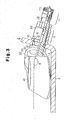
- Fig. 3 is a partially cross-sectional view illustrating a valve for a transmitter in a tire condition monitoring apparatus attached to a wheel.
-
- A valve for a transmitter in a tire condition monitoring apparatus according to one embodiment will now be described with reference to the drawings.
- As shown in Fig. 1(a), a
valve stem 10 has a threadedcap receiving portion 11 and a threadedfixing portion 12 for fixing thevalve stem 10 to a wheel. The diameter of thecap receiving portion 11 is less than the diameter of thefixing portion 12. Anengaging groove 13 is formed at a portion below thefixing portion 12. Below theengaging groove 13, that is, at a lower portion of thevalve stem 10 that is embedded in a tire, a pair ofarcuate grooves 14. A through hole for filling the tire with air extends through thevalve step 10. An air valve is provided in the through hole. - As shown in Fig. 1(b), an odd
shaped washer 20 has ancircular projecting edge 21 at an upper inside circumference. A pair ofarcuate recesses 22 are formed at the lower part of the odd shapedwasher 20. The radius of curvature of the recesses is substantially the same as thegrooves 14 shown in Fig. 1(a). - As shown in Fig. 1(c), a coupler, which is a
housing member 30, has a pair offlat plate portions 31, risingportion 32, and a pair ofarcuate projections 33. Theflat plate portions 31 are fixed to a casing 40 (see Fig. 3) that accommodates electronic elements. The risingportion 32 is located between theflat plate portions 31. Theprojections 33 extend from the risingportion 32. The radius of curvature of theprojections 33 is substantially the same as thearcuate recesses 22 shown in Fig. 1(b). The thickness of theprojection 33 is substantially the same as anaxial size 14a of thegrooves 14. Aspace 34 having an open end is defined between theprojections 33. Awidth 34a of thespace 34 is substantially the same as thedistance 14b between thegrooves 14. - A procedure for attaching a transmitter in the tire condition monitoring apparatus to a
wheel 2 will now be described. Thecasing 40 for accommodating electronic element has been fixed to theflat plate portions 31 of thehousing member 30 through insert molding in advance. - As shown in Fig. 2, an
O ring 15 is engaged with theengaging groove 13 of thevalve stem 10. Thevalve step 10 is fitted to the odd-shaped washer 20. Thegrooves 14 formed at a lower portion of thevalve stem 10 are fitted to theprojections 33 having an open end. That is, thegroove 14 of thevalve stem 10 is fitted to theprojections 33 to arrange thevalve stem 10 in thespace 34. At this time, the odd-shaped washer 20 is arranged such that no gap is created between thearcuate recesses 22 formed at the lower side of thewasher 20 and theprojections 33. - Subsequently, the
valve stem 10 is put through thevalve hole 3 from the inside of thewheel 2 so that theO ring 15 engaged with theengaging groove 13 of thevalve stem 10 to contact thevalve hole 3. Also, the projectingedge 21 formed on the upper inside of the odd-shaped washer 20 contacts thevalve hole 3. Accordingly, theO ring 15 is stopped in thevalve hole 3 to ensure the airtightness of the tire. - As shown in Fig. 3, when the
casing 40 is pressed against thedrop center 4 of thewheel 2, theprojections 33 are moved along thearcuate grooves 14 of thevalve stem 10. As a result, an installment angle defined by thevalve stem 10 and thecasing 40 is changed according to the cross-sectional shape of thewheel 2. In this state, thewasher 50 is fitted to thevalve stem 10 from the outside of thewheel 2. Then, avalve nut 60 is threaded to thefixing portion 12 of thevalve stem 10 from the outside of thewheel 2. - When threading the
valve nut 60, thegrooves 14 of thevalve stem 10 are engaged with theprojections 33 of thehousing portion 30. Further, thecasing 40 is pressed against thedrop center 4 of thewheel 2. Thus, when threading thevalve nut 60, thevalve stem 10 receives a force toward the outside of thewheel 2. As a result, the odd-shapedwasher 20 is pressed by thewheel 2 and thehousing portion 30. In other words, threading thevalve nut 60 to the fixingportion 12 of thevalve stem 10 determines the arrangement of the odd-shapedwasher 20 relative to thehousing portion 30. Accordingly, the position of thecasing 40 is determined relative to thevalve stem 10. - That is, the
valve stem 10 is attached to thewheel 2 simply by threading thevalve nut 60 to the fixingportion 12 of thevalve stem 10. At the same time, the threading of thevalve nut 60 determines the installment position of thecasing 40. In this manner, the transmitter of the tire condition monitoring apparatus is attached to thewheel 2. Thereafter, avalve cap 70 is threaded to thecap receiving portion 11 to complete the installment of the transmitter of the tire condition monitoring apparatus. - This embodiment has the following advantages.
- (1) The
grooves 14 formed at a lower portion of thevalve stem 10 are fitted to theprojections 33 having an open end. That is, thevalve stem 10 is arranged in thespace 34 defined by theprojections 33. Therefore, when thecasing 40 is pressed against thedrop center 4 of thewheel 2, theprojections 33 are moved along thearcuate grooves 14 of thevalve stem 10. As a result, an installment angle defined by thevalve stem 10 and thecasing 40 is changed according to the cross-sectional shape of thewheel 2. Thus, the transmitter of the tire condition monitoring apparatus can be installed inwheels 2 having various cross-sectional shapes. - (2) The valve stem 10 is attached to the
wheel 2 simply by threading thevalve nut 60 to the fixingportion 12 of thevalve stem 10. At the same time, the threading of thevalve nut 60 determines the installment position of thecasing 40. Therefore, the transmitter for the tire condition monitoring apparatus is easily attached to thewheel 2. Further, by adjusting the fastening amount of thevalve nut 60, the installment angle of thevalve stem 10 and thecasing 40 can be readjusted. - (3) Also, the transmitter for the tire condition
monitoring apparatus may be removed from the
wheel 2 and attached to a wheel having a different cross-sectional shape. That is, the present invention provides a highly versatile transmitter for tire condition monitoring apparatus. - (4) The transmitter for the tire condition monitoring
apparatus is attached to the
drop center 4 of thewheel 2. This prevents the beads of a tire from contacting thecasing 40 when attaching the tire to thewheel 2. Therefore, unlike the prior art, a plurality of reinforcing triangular ribs need not be provided between the flange and the outer surface of thecasing 40. It is needless to say that reinforcing ribs may be provided on the assumption that beads can contact thecasing 40. -
- It should be apparent to those skilled in the art that the present invention may be embodied in many other specific forms without departing from the spirit or scope of the invention. Particularly, it should be understood that the invention may be embodied in the following forms.
- In the illustrated embodiment, the
O ring 15 is provided at the engaginggroove 13 of thevalve stem 10. However, instead of theO ring 15, a grommet may be provided at the engaginggroove 13 of thevalve stem 10. - The data representing the condition of the tire may include the pressure and the temperature of the tire.
- The illustrated embodiment may be applied to any vehicle having tires. That is, the illustrated embodiment may be applied not only to four-wheel and two-wheel vehicles, but also to multi-wheel vehicles such as a bus and a truck.
- In the illustrated embodiment, the
arcuate grooves 14 of thevalve stem 10 are engaged with theprojections 33 of thehousing portion 30. However, thevalve stem 10 may have projections and thehousing portion 30 may have arcuate grooves. - Therefore, the present examples and embodiments are to be considered as illustrative and not restrictive and the invention is not to be limited to the details given herein, but may be modified within the scope and equivalence of the appended claims.
Claims (6)
- A transmitter of an apparatus for monitoring a condition of a tire, the transmitter comprising:a valve stem for permitting flow of air into the tire;an electronic element for transmitting a data representing the condition of the tire;a casing for accommodating the electronic element, the transmitter being characterized by:a coupler for coupling the valve stem to the casing such that an angle of the casing relative to the valve stem is adjustable be controlled.
- The transmitter according to claim 1, characterized in that a pair of grooves are formed in a proximal portion of the valve stem, wherein the coupler has a pair of projections, and wherein the projections are fit into the grooves.
- The transmitter according to claim 2, characterized in that each projection is movable along the corresponding groove.
- The transmitter according to claim 2 or 3, characterized in that the projections are arcuate.
- The transmitter according to any one of claims 2 to 4, characterized in that the projections extend from the casing, wherein the projections extend parallel to each other to define a space between the adjacent projections, and wherein a part of the valve stem between the grooves is fitted into the space.
- The transmitter according to any one of claims 1 to 5 further being characterized by a valve nut threaded to the valve stem to attach the valve stem to a wheel, wherein the angle of the casing is fixed by fastening the valve nut.
Applications Claiming Priority (2)
| Application Number | Priority Date | Filing Date | Title |
|---|---|---|---|
| JP2002373010 | 2002-12-24 | ||
| JP2002373010A JP2004203151A (en) | 2002-12-24 | 2002-12-24 | Valve for transmitter of tire condition monitoring device |
Publications (2)
| Publication Number | Publication Date |
|---|---|
| EP1433625A1 true EP1433625A1 (en) | 2004-06-30 |
| EP1433625B1 EP1433625B1 (en) | 2005-08-03 |
Family
ID=32463523
Family Applications (1)
| Application Number | Title | Priority Date | Filing Date |
|---|---|---|---|
| EP03022531A Expired - Lifetime EP1433625B1 (en) | 2002-12-24 | 2003-10-02 | Transmitter in tire condition monitoring apparatus |
Country Status (4)
| Country | Link |
|---|---|
| US (1) | US6952957B2 (en) |
| EP (1) | EP1433625B1 (en) |
| JP (1) | JP2004203151A (en) |
| DE (1) | DE60301193T2 (en) |
Cited By (11)
| Publication number | Priority date | Publication date | Assignee | Title |
|---|---|---|---|---|
| DE102005027002A1 (en) * | 2005-06-10 | 2006-12-21 | Lite-On Automotive Corp., Kaohsiung | Device for sensing the tire condition and method for installing the same |
| FR2907048A1 (en) * | 2006-10-16 | 2008-04-18 | Siemens Vdo Automotive Sas | Electronic unit for e.g. pressure measurement, in motor vehicle wheel, has insert and return to delimit housing directly receiving head, where insert is formed of metal plate to support locking face, and has indentation for passage of body |
| ITCR20080027A1 (en) * | 2008-12-12 | 2010-06-13 | Wonder Spa | VALVE FOR INFLATING TIRES ASSOCIATED WITH A TRANSDUCER FOR TPMS TECHNOLOGY |
| CN101508232B (en) * | 2008-02-14 | 2010-11-10 | 橙的电子股份有限公司 | Air nozzle of multi-screw locking angle wireless tire pressure detector |
| CN104487267A (en) * | 2012-07-30 | 2015-04-01 | 法国大陆汽车公司 | Wheel module comprising an elastically deformable inflation valve for a tyre pressure monitoring system |
| GB2577170A (en) * | 2018-07-31 | 2020-03-18 | Sensata Technologies Inc | Tyre pressure monitor and variable angle mounting |
| US10807421B2 (en) | 2018-07-31 | 2020-10-20 | Sensata Techologies, Inc. | Tire pressure monitor with variable angle mounting |
| GB2589142A (en) * | 2019-11-25 | 2021-05-26 | Continental Automotive Gmbh | Adapter, Valve stem, tyre parameter monitoring system and method for mounting a tyre parameter monitoring system onto a wheel rim |
| WO2021154387A1 (en) * | 2020-01-31 | 2021-08-05 | Sensata Technologies Inc. | Tire pressure monitoring module with thru-valve construction |
| US11084336B2 (en) | 2018-04-30 | 2021-08-10 | Sensata Technologies, Inc. | Methods and apparatus for determining the orientation of a tire mounted device |
| TWI828200B (en) * | 2022-06-21 | 2024-01-01 | 系統電子工業股份有限公司 | Improved tire pressure detector fixed structure |
Families Citing this family (21)
| Publication number | Priority date | Publication date | Assignee | Title |
|---|---|---|---|---|
| US6959597B2 (en) * | 2002-08-01 | 2005-11-01 | Pacific Industrial Co., Ltd. | Transmitter for tire state monitoring apparatus |
| JP4166735B2 (en) * | 2004-08-04 | 2008-10-15 | 太平洋工業株式会社 | Transmitter unit in tire condition monitoring device |
| US7454965B2 (en) * | 2005-09-19 | 2008-11-25 | Trw Automotive U.S. Llc | Method and apparatus for mounting a tire pressure monitoring device |
| JP5109332B2 (en) * | 2006-10-26 | 2012-12-26 | 横浜ゴム株式会社 | Vehicle information detection / transmission device mounting jig and vehicle information detection / transmission device assembly |
| CN200988402Y (en) * | 2006-12-04 | 2007-12-12 | 上海保隆汽车科技股份有限公司 | Combined device for stepped adjustable tire pressure monitoring sensor signal box |
| US20080302425A1 (en) * | 2007-06-05 | 2008-12-11 | Continental Automotive Systems Us, Inc. | Formed Flange For Pressure Monitoring Valve Stem Mount |
| US7536904B1 (en) * | 2008-02-19 | 2009-05-26 | Orange Electronic Co., Ltd. | Tire pressure detector and valve stem assembly |
| US7775095B2 (en) * | 2008-02-20 | 2010-08-17 | Orange Electronic Co., Ltd. | Valve stem with a connecting cap for a tire pressure detector |
| US7870866B2 (en) * | 2008-03-10 | 2011-01-18 | Orange Electronic Co., Ltd. | Valve stem assembly for clamping a tire pressure detector |
| US8047068B2 (en) * | 2008-08-01 | 2011-11-01 | Schrader Electronics, Inc. | Snap-in tire valve |
| KR101137813B1 (en) * | 2009-04-01 | 2012-04-18 | 씨트론 주식회사 | Tire Pressure Monitoring System and Tire Pressure Sensor thereof |
| KR101272558B1 (en) * | 2011-03-28 | 2013-06-10 | 영화테크(주) | Tire pressure monitoring system |
| KR101198924B1 (en) * | 2011-11-24 | 2012-11-09 | 서성원 | Tire pressure sensor module in tire pressure monitoring system |
| US8474312B2 (en) * | 2011-12-02 | 2013-07-02 | Josn Electronic Co., Ltd. | Tire pressure monitor |
| JP5918027B2 (en) * | 2012-05-23 | 2016-05-18 | 太平洋工業株式会社 | Tire valve unit |
| JP6175415B2 (en) * | 2014-06-26 | 2017-08-02 | 太平洋工業株式会社 | Tire valve unit |
| WO2016008091A1 (en) * | 2014-07-15 | 2016-01-21 | 深圳市道通科技股份有限公司 | Tyre pressure sensor assembly and wheel comprising same |
| EP3468817B1 (en) * | 2016-06-13 | 2020-09-16 | Huf Baolong Electronics Bretten GmbH | System for monitoring tyre pressure and method for mounting a tyre pressure monitoring system on a rim |
| EP3450222B1 (en) * | 2016-12-26 | 2021-09-15 | Pacific Industrial Co., Ltd. | Tire condition detecting apparatus, clamp-in valve and tire valve unit |
| CN112537176B (en) | 2019-09-20 | 2022-12-20 | 大陆汽车有限公司 | Adapter, valve stem, tire parameter monitoring system and method for mounting a tire parameter monitoring system on a rim |
| EP4173854B1 (en) | 2021-09-15 | 2025-07-30 | Pacific Industrial Co., Ltd. | Tire valve |
Citations (2)
| Publication number | Priority date | Publication date | Assignee | Title |
|---|---|---|---|---|
| US5844131A (en) * | 1995-06-26 | 1998-12-01 | Alligator Ventilfabrik Gmbh | Tire pressure sensor apparatus for a pneumatic tire of a vehicle |
| US6055855A (en) * | 1999-05-26 | 2000-05-02 | Trw Inc. | Tire pressure sensor wheel attachment apparatus |
Family Cites Families (6)
| Publication number | Priority date | Publication date | Assignee | Title |
|---|---|---|---|---|
| US2866658A (en) * | 1955-12-29 | 1958-12-30 | Ludlow Valve Mfg Co Inc | Device for adjusting the length of a valve stem |
| US5080575A (en) * | 1991-05-17 | 1992-01-14 | Eastman Kodak Company | Adjustable valve stem apparatus for valve gated injection molding devices |
| US5183069A (en) * | 1991-05-17 | 1993-02-02 | Eastman Kodak Company | Adjustable valve stem apparatus for valve gated injection molding devices |
| JP3317905B2 (en) | 1998-09-07 | 2002-08-26 | 太平洋工業株式会社 | Casing structure of transmitter for tire pressure warning device |
| IT1315828B1 (en) * | 1999-02-18 | 2003-03-26 | Daimler Chrysler Ag | FIXING DEVICE TO CONNECT A SPRING PLATE TO A VALVE WITH THE VALVE STEM. |
| US6959597B2 (en) * | 2002-08-01 | 2005-11-01 | Pacific Industrial Co., Ltd. | Transmitter for tire state monitoring apparatus |
-
2002
- 2002-12-24 JP JP2002373010A patent/JP2004203151A/en active Pending
-
2003
- 2003-10-02 DE DE60301193T patent/DE60301193T2/en not_active Expired - Fee Related
- 2003-10-02 EP EP03022531A patent/EP1433625B1/en not_active Expired - Lifetime
- 2003-10-07 US US10/680,575 patent/US6952957B2/en not_active Expired - Lifetime
Patent Citations (2)
| Publication number | Priority date | Publication date | Assignee | Title |
|---|---|---|---|---|
| US5844131A (en) * | 1995-06-26 | 1998-12-01 | Alligator Ventilfabrik Gmbh | Tire pressure sensor apparatus for a pneumatic tire of a vehicle |
| US6055855A (en) * | 1999-05-26 | 2000-05-02 | Trw Inc. | Tire pressure sensor wheel attachment apparatus |
Cited By (19)
| Publication number | Priority date | Publication date | Assignee | Title |
|---|---|---|---|---|
| DE102005027002A1 (en) * | 2005-06-10 | 2006-12-21 | Lite-On Automotive Corp., Kaohsiung | Device for sensing the tire condition and method for installing the same |
| FR2907048A1 (en) * | 2006-10-16 | 2008-04-18 | Siemens Vdo Automotive Sas | Electronic unit for e.g. pressure measurement, in motor vehicle wheel, has insert and return to delimit housing directly receiving head, where insert is formed of metal plate to support locking face, and has indentation for passage of body |
| CN101508232B (en) * | 2008-02-14 | 2010-11-10 | 橙的电子股份有限公司 | Air nozzle of multi-screw locking angle wireless tire pressure detector |
| ITCR20080027A1 (en) * | 2008-12-12 | 2010-06-13 | Wonder Spa | VALVE FOR INFLATING TIRES ASSOCIATED WITH A TRANSDUCER FOR TPMS TECHNOLOGY |
| WO2010067197A1 (en) * | 2008-12-12 | 2010-06-17 | Wonder Spa | Tyre inflation valve connectable to a transducer |
| US8490479B2 (en) | 2008-12-12 | 2013-07-23 | Wonder Spa | Tyre inflation valve connectable to a transducer |
| US9669668B2 (en) | 2012-07-30 | 2017-06-06 | Continental Automotive France | Wheel module comprising an elastically deformable inflation valve for a tyre pressure monitoring system |
| CN104487267B (en) * | 2012-07-30 | 2017-03-01 | 法国大陆汽车公司 | Wheel structure module including the charge valve of the elastically deformable of system for monitoring pressure in tyre |
| CN104487267A (en) * | 2012-07-30 | 2015-04-01 | 法国大陆汽车公司 | Wheel module comprising an elastically deformable inflation valve for a tyre pressure monitoring system |
| US11084336B2 (en) | 2018-04-30 | 2021-08-10 | Sensata Technologies, Inc. | Methods and apparatus for determining the orientation of a tire mounted device |
| GB2577170A (en) * | 2018-07-31 | 2020-03-18 | Sensata Technologies Inc | Tyre pressure monitor and variable angle mounting |
| US10807421B2 (en) | 2018-07-31 | 2020-10-20 | Sensata Techologies, Inc. | Tire pressure monitor with variable angle mounting |
| GB2577170B (en) * | 2018-07-31 | 2021-08-25 | Sensata Technologies Inc | Tyre pressure monitor with variable angle mounting |
| US11338629B2 (en) | 2018-07-31 | 2022-05-24 | Sensata Technologies, Inc. | Tire pressure monitor with variable angle mounting |
| GB2589142A (en) * | 2019-11-25 | 2021-05-26 | Continental Automotive Gmbh | Adapter, Valve stem, tyre parameter monitoring system and method for mounting a tyre parameter monitoring system onto a wheel rim |
| GB2589142B (en) * | 2019-11-25 | 2022-03-23 | Continental Automotive Gmbh | Adapter, valve stem, tyre parameter monitoring system and method for mounting a tyre parameter monitoring system onto a wheel rim |
| WO2021154387A1 (en) * | 2020-01-31 | 2021-08-05 | Sensata Technologies Inc. | Tire pressure monitoring module with thru-valve construction |
| US11385117B2 (en) | 2020-01-31 | 2022-07-12 | Sensata Technologies, Inc. | Tire pressure monitoring module with thru-valve construction |
| TWI828200B (en) * | 2022-06-21 | 2024-01-01 | 系統電子工業股份有限公司 | Improved tire pressure detector fixed structure |
Also Published As
| Publication number | Publication date |
|---|---|
| US6952957B2 (en) | 2005-10-11 |
| EP1433625B1 (en) | 2005-08-03 |
| DE60301193D1 (en) | 2005-09-08 |
| DE60301193T2 (en) | 2006-06-01 |
| JP2004203151A (en) | 2004-07-22 |
| US20040119584A1 (en) | 2004-06-24 |
Similar Documents
| Publication | Publication Date | Title |
|---|---|---|
| EP1433625B1 (en) | Transmitter in tire condition monitoring apparatus | |
| US20120017672A1 (en) | Tire pressure monitoring system and tire pressure sensor thereof | |
| US6959597B2 (en) | Transmitter for tire state monitoring apparatus | |
| EP1452347B1 (en) | Casing structure of transmitter for use in tire condition monitoring apparatus | |
| US7587935B2 (en) | Electronic unit for measuring operating parameters of a vehicle wheel, comprising an electronic box and an inflation valve of the snap-in type | |
| EP1449683B1 (en) | Transmitter mounting structure for tire condition monitoring apparatus | |
| JP4522953B2 (en) | Tire valve unit | |
| CN106660415B (en) | Tyre pressure sensor component and wheel including it | |
| EP1321314A2 (en) | Transmitter of tire condition monitoring apparatus | |
| CN102245407A (en) | Tyre inflation valve connectable to a transducer | |
| US8661886B2 (en) | Valve stem grommet structure | |
| US20180319228A1 (en) | Wheel for an air maintenance tire system | |
| EP1356961A2 (en) | Mounting structure of transmitter for tire condition monitoring apparatus | |
| US20030217595A1 (en) | Remote tire pressure monitoring system with plastic thin-walled valve cap and method of installing the monitoring system | |
| US9517666B2 (en) | Vehicle wheel and tire information acquisition device fitting | |
| JP6487689B2 (en) | Snap-in inlet and connection method for air maintenance tires | |
| US7187272B2 (en) | Casing structure of transmitter of tire condition monitoring apparatus | |
| US8650945B2 (en) | Retention member on valve stem sealing grommet | |
| US6486772B1 (en) | Pressure indicating device for tube-less tire | |
| US20050045256A1 (en) | Wheel and a Wheel Rim | |
| KR100539019B1 (en) | A transmitter casing apparatus of a tire pressure monitoring system of an automobile | |
| KR200218767Y1 (en) | a tire which has the central wall and it's a wheel | |
| KR20220143345A (en) | Rim for prevention separating pneumatic tire and vehicle wheel having the rim | |
| JP2010076474A (en) | Pneumatic tire | |
| JP2013067290A (en) | Wheel for automobile |
Legal Events
| Date | Code | Title | Description |
|---|---|---|---|
| PUAI | Public reference made under article 153(3) epc to a published international application that has entered the european phase |
Free format text: ORIGINAL CODE: 0009012 |
|
| AK | Designated contracting states |
Kind code of ref document: A1 Designated state(s): AT BE BG CH CY CZ DE DK EE ES FI FR GB GR HU IE IT LI LU MC NL PT RO SE SI SK TR |
|
| AX | Request for extension of the european patent |
Extension state: AL LT LV MK |
|
| 17P | Request for examination filed |
Effective date: 20040617 |
|
| 17Q | First examination report despatched |
Effective date: 20040730 |
|
| GRAP | Despatch of communication of intention to grant a patent |
Free format text: ORIGINAL CODE: EPIDOSNIGR1 |
|
| AKX | Designation fees paid |
Designated state(s): DE FR IT |
|
| GRAS | Grant fee paid |
Free format text: ORIGINAL CODE: EPIDOSNIGR3 |
|
| GRAA | (expected) grant |
Free format text: ORIGINAL CODE: 0009210 |
|
| AK | Designated contracting states |
Kind code of ref document: B1 Designated state(s): DE FR IT |
|
| REF | Corresponds to: |
Ref document number: 60301193 Country of ref document: DE Date of ref document: 20050908 Kind code of ref document: P |
|
| ET | Fr: translation filed | ||
| PLBE | No opposition filed within time limit |
Free format text: ORIGINAL CODE: 0009261 |
|
| STAA | Information on the status of an ep patent application or granted ep patent |
Free format text: STATUS: NO OPPOSITION FILED WITHIN TIME LIMIT |
|
| 26N | No opposition filed |
Effective date: 20060504 |
|
| PGFP | Annual fee paid to national office [announced via postgrant information from national office to epo] |
Ref country code: DE Payment date: 20061023 Year of fee payment: 4 |
|
| PGFP | Annual fee paid to national office [announced via postgrant information from national office to epo] |
Ref country code: IT Payment date: 20061031 Year of fee payment: 4 |
|
| PG25 | Lapsed in a contracting state [announced via postgrant information from national office to epo] |
Ref country code: DE Free format text: LAPSE BECAUSE OF NON-PAYMENT OF DUE FEES Effective date: 20080501 |
|
| REG | Reference to a national code |
Ref country code: FR Ref legal event code: ST Effective date: 20080630 |
|
| PGFP | Annual fee paid to national office [announced via postgrant information from national office to epo] |
Ref country code: FR Payment date: 20061016 Year of fee payment: 4 |
|
| PG25 | Lapsed in a contracting state [announced via postgrant information from national office to epo] |
Ref country code: FR Free format text: LAPSE BECAUSE OF NON-PAYMENT OF DUE FEES Effective date: 20071031 |
|
| PG25 | Lapsed in a contracting state [announced via postgrant information from national office to epo] |
Ref country code: IT Free format text: LAPSE BECAUSE OF NON-PAYMENT OF DUE FEES Effective date: 20071002 |