JP6487689B2 - Snap-in inlet and connection method for air maintenance tires - Google Patents
Snap-in inlet and connection method for air maintenance tires Download PDFInfo
- Publication number
- JP6487689B2 JP6487689B2 JP2014253747A JP2014253747A JP6487689B2 JP 6487689 B2 JP6487689 B2 JP 6487689B2 JP 2014253747 A JP2014253747 A JP 2014253747A JP 2014253747 A JP2014253747 A JP 2014253747A JP 6487689 B2 JP6487689 B2 JP 6487689B2
- Authority
- JP
- Japan
- Prior art keywords
- air
- inlet
- sidewall
- tire
- conduit
- Prior art date
- Legal status (The legal status is an assumption and is not a legal conclusion. Google has not performed a legal analysis and makes no representation as to the accuracy of the status listed.)
- Active
Links
- 238000012423 maintenance Methods 0.000 title claims description 18
- 238000000034 method Methods 0.000 title claims description 7
- 230000004044 response Effects 0.000 claims description 4
- 238000005452 bending Methods 0.000 claims description 3
- 238000004891 communication Methods 0.000 claims 1
- 230000026058 directional locomotion Effects 0.000 claims 1
- 230000033001 locomotion Effects 0.000 claims 1
- 230000013011 mating Effects 0.000 claims 1
- 230000001105 regulatory effect Effects 0.000 claims 1
- 239000007787 solid Substances 0.000 claims 1
- 235000001674 Agaricus brunnescens Nutrition 0.000 description 8
- 229920001971 elastomer Polymers 0.000 description 8
- 230000002572 peristaltic effect Effects 0.000 description 8
- 230000007423 decrease Effects 0.000 description 4
- 239000000463 material Substances 0.000 description 4
- 239000011324 bead Substances 0.000 description 3
- 230000000295 complement effect Effects 0.000 description 3
- 230000008439 repair process Effects 0.000 description 3
- 239000000853 adhesive Substances 0.000 description 2
- 230000001070 adhesive effect Effects 0.000 description 2
- 150000001875 compounds Chemical class 0.000 description 2
- 230000007246 mechanism Effects 0.000 description 2
- 240000007440 Agaricus campestris Species 0.000 description 1
- 241000254043 Melolonthinae Species 0.000 description 1
- 238000005299 abrasion Methods 0.000 description 1
- 230000004323 axial length Effects 0.000 description 1
- 238000009530 blood pressure measurement Methods 0.000 description 1
- 239000011248 coating agent Substances 0.000 description 1
- 238000000576 coating method Methods 0.000 description 1
- 230000008602 contraction Effects 0.000 description 1
- 238000009792 diffusion process Methods 0.000 description 1
- 239000000806 elastomer Substances 0.000 description 1
- 239000000446 fuel Substances 0.000 description 1
- 238000010348 incorporation Methods 0.000 description 1
- 238000009434 installation Methods 0.000 description 1
- 238000004519 manufacturing process Methods 0.000 description 1
- 238000012986 modification Methods 0.000 description 1
- 230000004048 modification Effects 0.000 description 1
- 238000012544 monitoring process Methods 0.000 description 1
- 230000008855 peristalsis Effects 0.000 description 1
- 239000004033 plastic Substances 0.000 description 1
- 230000003252 repetitive effect Effects 0.000 description 1
- 230000002441 reversible effect Effects 0.000 description 1
- 238000000926 separation method Methods 0.000 description 1
- 239000000126 substance Substances 0.000 description 1
- 239000011800 void material Substances 0.000 description 1
Images


Classifications
-
- B—PERFORMING OPERATIONS; TRANSPORTING
- B60—VEHICLES IN GENERAL
- B60C—VEHICLE TYRES; TYRE INFLATION; TYRE CHANGING; CONNECTING VALVES TO INFLATABLE ELASTIC BODIES IN GENERAL; DEVICES OR ARRANGEMENTS RELATED TO TYRES
- B60C23/00—Devices for measuring, signalling, controlling, or distributing tyre pressure or temperature, specially adapted for mounting on vehicles; Arrangement of tyre inflating devices on vehicles, e.g. of pumps or of tanks; Tyre cooling arrangements
- B60C23/10—Arrangement of tyre-inflating pumps mounted on vehicles
- B60C23/12—Arrangement of tyre-inflating pumps mounted on vehicles operated by a running wheel
- B60C23/121—Arrangement of tyre-inflating pumps mounted on vehicles operated by a running wheel the pumps being mounted on the tyres
- B60C23/123—Elongate peristaltic pumps
-
- B—PERFORMING OPERATIONS; TRANSPORTING
- B60—VEHICLES IN GENERAL
- B60C—VEHICLE TYRES; TYRE INFLATION; TYRE CHANGING; CONNECTING VALVES TO INFLATABLE ELASTIC BODIES IN GENERAL; DEVICES OR ARRANGEMENTS RELATED TO TYRES
- B60C23/00—Devices for measuring, signalling, controlling, or distributing tyre pressure or temperature, specially adapted for mounting on vehicles; Arrangement of tyre inflating devices on vehicles, e.g. of pumps or of tanks; Tyre cooling arrangements
- B60C23/10—Arrangement of tyre-inflating pumps mounted on vehicles
- B60C23/12—Arrangement of tyre-inflating pumps mounted on vehicles operated by a running wheel
- B60C23/135—Arrangement of tyre-inflating pumps mounted on vehicles operated by a running wheel activated due to tyre deformation
-
- B—PERFORMING OPERATIONS; TRANSPORTING
- B60—VEHICLES IN GENERAL
- B60C—VEHICLE TYRES; TYRE INFLATION; TYRE CHANGING; CONNECTING VALVES TO INFLATABLE ELASTIC BODIES IN GENERAL; DEVICES OR ARRANGEMENTS RELATED TO TYRES
- B60C29/00—Arrangements of tyre-inflating valves to tyres or rims; Accessories for tyre-inflating valves, not otherwise provided for
- B60C29/04—Connection to tyres or inner tubes
-
- Y—GENERAL TAGGING OF NEW TECHNOLOGICAL DEVELOPMENTS; GENERAL TAGGING OF CROSS-SECTIONAL TECHNOLOGIES SPANNING OVER SEVERAL SECTIONS OF THE IPC; TECHNICAL SUBJECTS COVERED BY FORMER USPC CROSS-REFERENCE ART COLLECTIONS [XRACs] AND DIGESTS
- Y10—TECHNICAL SUBJECTS COVERED BY FORMER USPC
- Y10T—TECHNICAL SUBJECTS COVERED BY FORMER US CLASSIFICATION
- Y10T152/00—Resilient tires and wheels
- Y10T152/10—Tires, resilient
- Y10T152/10495—Pneumatic tire or inner tube
-
- Y—GENERAL TAGGING OF NEW TECHNOLOGICAL DEVELOPMENTS; GENERAL TAGGING OF CROSS-SECTIONAL TECHNOLOGIES SPANNING OVER SEVERAL SECTIONS OF THE IPC; TECHNICAL SUBJECTS COVERED BY FORMER USPC CROSS-REFERENCE ART COLLECTIONS [XRACs] AND DIGESTS
- Y10—TECHNICAL SUBJECTS COVERED BY FORMER USPC
- Y10T—TECHNICAL SUBJECTS COVERED BY FORMER US CLASSIFICATION
- Y10T29/00—Metal working
- Y10T29/49—Method of mechanical manufacture
- Y10T29/49481—Wheel making
- Y10T29/49492—Land wheel
- Y10T29/49538—Tire making
Description
本発明は、一般に、空気維持タイヤに関し、特に、サイドウォールに配置された管状のポンプ機構と、タイヤに取り付けられた入口ハウジングに取り付けられた空気入口組立体とを有するタイヤに関する。 The present invention relates generally to air maintenance tires, and more particularly to a tire having a tubular pump mechanism disposed on a sidewall and an air inlet assembly attached to an inlet housing attached to the tire.
通常の空気拡散により、時間とともにタイヤ圧は減少する。タイヤの通常の状態は、膨張した状態である。したがって、ドライバーは、タイヤ圧を維持するために繰り返し作業を行う必要があり、さもなければ、燃費およびタイヤ寿命の低下と、自動車のブレーキ性能およびハンドリング性能の低下に直面することになる。タイヤ圧が著しく低いときにドライバーに警告するタイヤ圧監視システムが提案されている。 With normal air diffusion, the tire pressure decreases with time. The normal state of the tire is an inflated state. Therefore, the driver needs to perform repetitive work to maintain the tire pressure, or face a decrease in fuel consumption and tire life and a decrease in the braking performance and handling performance of the automobile. A tire pressure monitoring system has been proposed that warns the driver when tire pressure is extremely low.
しかしながら、そのようなシステムは、推奨圧力までタイヤを再膨張させるように警告が発せられたときに、ドライバーによる救済措置に依然として依存している。したがって、ドライバーの介入を必要とせずに経時的なタイヤ圧のいかなる減少も補償するために、タイヤ圧を維持する空気維持ポンプシステムをタイヤ内に組み込むことが望まれている。 However, such a system still relies on driver relief when a warning is issued to reinflate the tire to the recommended pressure. Therefore, it is desirable to incorporate an air maintenance pump system in the tire that maintains tire pressure to compensate for any decrease in tire pressure over time without requiring driver intervention.
本発明の一態様では、空気維持タイヤが、タイヤのインナーライナーに固定された空気入口ハウジングを含んでいる。細長いサイドウォール空気通路が、第1のタイヤサイドウォール内に組み込まれ、回転するタイヤの接地面(フットプリント)から第1のサイドウォールへと伝わる曲げ歪みに応答して、拡大した直径から実質的に縮小した直径へとセグメントごとに圧縮され、それにより、サイドウォール空気通路に沿ってセグメントごとに強制的に空気を送り込むように動作可能に配置されている。細長い管状の入口導管が、入口ハウジングからサイドウォール空気通路まで空気を送るために設けられている。吸気導管が、タイヤの外部からの空気を、第1のサイドウォールを通ってタイヤインナーライナーまで送り、さらに入口ハウジングへと送るために設けられている。入口導管および吸気導管は、入口ハウジングによって形成された細長い第1および第2のソケットにそれぞれ取り付けられるとともに、第1および第2のソケットからそれぞれ取り外される。入口導管および吸気導管は、入口ハウジングの各ソケットに対する迅速な接続/分離を容易にするために、第1および第2のソケット内の各環状戻り止めと嵌合する複数のスナップ式の環状リブであって、互いに離れて位置する複数のスナップ式の環状リブを有している。 In one aspect of the present invention, an air maintenance tire includes an air inlet housing secured to the inner liner of the tire. An elongated sidewall air passage is incorporated into the first tire sidewall and is substantially from an enlarged diameter in response to bending strain transmitted from the rotating tire's ground plane (footprint) to the first sidewall. Are operably arranged to force air into each segment along the sidewall air passages. An elongated tubular inlet conduit is provided for sending air from the inlet housing to the sidewall air passage. An intake conduit is provided for sending air from outside the tire through the first sidewall to the tire inner liner and further to the inlet housing. The inlet conduit and the intake conduit are respectively attached to and removed from the elongated first and second sockets formed by the inlet housing. The inlet and intake conduits are a plurality of snap-type annular ribs that mate with each annular detent in the first and second sockets to facilitate quick connection / disconnection to each socket of the inlet housing. A plurality of snap-type annular ribs are provided apart from each other.
(定義)
ここで、本明細書で使用される用語について定義する。
(Definition)
Here, terms used in this specification are defined.
タイヤの「アスペクト比」は、タイヤの断面幅(SW)に対する断面高さ(SH)の比を意味し、百分率で表現するために100を乗じたものを意味する。 “Aspect ratio” of a tire means a ratio of a cross-sectional height (SH) to a cross-sectional width (SW) of the tire, and means a value multiplied by 100 to express it as a percentage.
「非対称トレッド」は、タイヤの中心面つまり赤道面EPに関して対称ではないトレッドパターンを有するトレッドを意味する。 “Asymmetric tread” means a tread having a tread pattern that is not symmetric with respect to the center plane or equator plane EP of the tire.
「軸方向の」および「軸方向に」は、タイヤの回転軸に平行なラインまたは方向を意味する。 “Axial” and “in the axial direction” mean a line or direction parallel to the axis of rotation of the tire.
「チェーファー」は、タイヤビードの外側周囲に配置され、リムに対する摩耗および切断からコードプライを保護し、リム上方のたわみを分散させる、幅の狭い材料ストリップである。 A “chafer” is a narrow strip of material that is placed around the outside of the tire bead and protects the cord ply from abrasion and cutting against the rim and distributes the deflection above the rim.
「周方向」は、軸方向に垂直な環状のトレッドの表面の周囲に沿って延びるラインまたは方向を意味する。 “Circumferential” means a line or direction extending along the circumference of the surface of the annular tread perpendicular to the axial direction.
「赤道中心面(CP)」は、タイヤの回転軸に垂直でトレッドの中心を通る平面を意味する。 “Equatorial center plane (CP)” means a plane perpendicular to the tire's axis of rotation and passing through the center of the tread.
「フットプリント」は、速度が零で、標準荷重および標準圧において、平坦な面と接触するタイヤトレッドの接地面または接地領域を意味する。 “Footprint” means the contact surface or contact area of the tire tread that is in contact with a flat surface at zero speed and standard load and pressure.
「溝」は、トレッドの周囲を周方向または横方向に、直線状、曲線状、またはジグザグ状に延びることができる、トレッド内の細長い空隙領域を意味する。周方向および横方向に延びる溝は、共通部分を有する場合もある。「溝の幅」は、その幅が問題となっている、溝または溝部分によって占められる表面積を、この溝または溝部分の長さで割ったものに等しく、したがって、溝の幅は、溝の全長での平均幅である。溝は、タイヤ内で様々な深さを有していてよい。溝の深さは、トレッドの円周にわたって変化していてよく、あるいは、ある溝の深さが、一定であるが、タイヤ内の別の溝の深さとは異なっていてよい。そのような幅狭または幅広の溝は、相互に連結する幅広の周方向溝と比べて、実質的に小さい深さを有する場合、関連するトレッド領域でリブのような性質を保持する傾向がある「タイバー」を形成すると見なされる。 “Groove” means an elongated void area in a tread that can extend circumferentially or laterally around the tread in a straight, curved, or zigzag manner. The grooves extending in the circumferential direction and the lateral direction may have a common portion. The “groove width” is equal to the surface area occupied by the groove or groove portion, whose width is an issue, divided by the length of the groove or groove portion, so the groove width is the groove width. The average width over the entire length. The grooves may have various depths within the tire. The groove depth may vary over the circumference of the tread, or the depth of one groove may be constant but different from the depth of another groove in the tire. Such narrow or wide grooves tend to retain rib-like properties in the associated tread region when they have a substantially smaller depth compared to the wide circumferential grooves that interconnect. It is considered to form a “tie bar”.
「車内側」は、タイヤがホイールに取り付けられ、そのホイールが車両に取り付けられたときの、タイヤの車両に最も近い側を意味する。 “Vehicle interior” means the side of the tire closest to the vehicle when the tire is attached to a wheel and the wheel is attached to the vehicle.
「横方向」は、軸方向を意味する。 “Lateral direction” means an axial direction.
「横方向縁部」は、赤道中心面に平行なラインであって、標準荷重および標準タイヤ圧において測定された、軸方向の最も外側のトレッドの接地面つまりフットプリントの接線を意味する。 “Lateral edge” means a line parallel to the center plane of the equator and tangent to the contact surface or footprint of the outermost tread in the axial direction, measured at standard load and standard tire pressure.
「正味接地面積」は、トレッド全周にわたる横方向縁部同士の間の接地トレッド要素の全面積を、横方向縁部同士の間のトレッド全体の総面積で割ったものを意味する。 “Net contact area” means the total area of the contact tread element between the lateral edges over the entire tread circumference divided by the total area of the entire tread between the lateral edges.
「非方向性トレッド」は、好適な前進方向を有していないトレッドであって、トレッドバターンが好適な走行方向に揃うようにする特定のホイールポジションで車両に配置する必要のないトレッドを意味する。逆に、方向性トレッドパターンは、特定のホイールポジションを必要とする好適な走行方向を有している。 “Non-directional tread” means a tread that does not have a preferred forward direction and does not need to be placed in the vehicle at a particular wheel position that allows the tread pattern to align with the preferred direction of travel. . Conversely, the directional tread pattern has a suitable travel direction that requires a specific wheel position.
「車外側」は、タイヤがホイールに取り付けられ、そのホイールが車両に取り付けられたときの、タイヤの車両から最も遠い側を意味する。 “Outside the vehicle” means the side of the tire farthest from the vehicle when the tire is attached to a wheel and the wheel is attached to the vehicle.
「蠕動」は、空気などの内包物質を管状流路に沿って推進させる波状収縮による動作を意味する。 “Peristalsis” means an operation by wave-like contraction that drives an inclusion substance such as air along the tubular flow path.
「半径方向の」および「半径方向に」は、タイヤの回転軸に向かって放射状に延びる方向、または回転軸から離れるように放射状に延びる方向を意味する。 “Radial” and “radially” mean a direction that extends radially toward the axis of rotation of the tire or a direction that extends radially away from the axis of rotation.
「リブ」は、少なくとも1つの周方向溝と、同等の第2の溝または横方向縁部のいずれかとによって規定された、トレッド上を周方向に延びるゴムのストリップであって、完全な深さの溝によって横方向に分割されていないゴムのストリップを意味する。 A “rib” is a strip of rubber extending circumferentially over a tread, defined by at least one circumferential groove and either an equivalent second groove or a lateral edge, to a full depth Means a strip of rubber that is not laterally divided by grooves.
「サイプ」は、トレッド面を細分し、トラクションを改善する、タイヤのトレッド要素内に成形された小さいスロットを意味し、サイプは、一般に幅が狭く、タイヤのフットプリント内で開いれたままである溝とは対照的に、タイヤのフットプリント内で閉じている。 "Sipe" means a small slot molded into the tread element of the tire that subdivides the tread surface and improves traction, and the sipe is generally narrow and remains open in the tire footprint In contrast to the groove, it is closed in the tire footprint.
「トレッド要素」または「トラクション要素」は、溝に隣接する形状を有することにより規定された、リブ要素またはブロック要素を意味する。 “Tread element” or “traction element” means a rib or block element defined by having a shape adjacent to a groove.
「トレッドアーク幅」は、トレッドの横方向縁部同士の間で測定された、トレッドの円弧長を意味する。 “Tread Arc Width” means the arc length of the tread measured between the lateral edges of the tread.
本発明について、添付した図面を参照して、一例を挙げて説明する。 The present invention will be described by way of example with reference to the accompanying drawings.
図1から図3を参照すると、タイヤ組立体10は、タイヤ12と、タイヤをベースとした蠕動ポンプ組立体14とを含んでいる。タイヤ12は、車両に用いるために、従来の方法でリム(図示せず)に取り付けられている。タイヤは、従来構造を有し、互いに対向するビード領域20,22からクラウンつまりタイヤトレッド領域24までそれぞれ延びる一対のサイドウォール16,18を有している。タイヤおよびリムが、タイヤインナーライナー26によって画定されたタイヤキャビティ28を包囲している。
Referring to FIGS. 1-3, the
図1から図3に見られるように、蠕動ポンプ組立体14は、環状の空気通路32を包囲する環状の空気チューブ34を含んでいる。チューブ34は、プラスチックやゴム化合物など、弾性および可撓性を有する材料であって、外力を受けて平らな状態に変形し、その力が取り除かれると、断面がほぼ円形の元の状態に回復するという、繰り返しの変形サイクルに耐えることができる材料から形成されている。チューブは、本明細書に記載された目的のために十分な量の空気を通過させるのに十分な直径であって、タイヤ組立体内部の動作可能な位置にチューブを配置可能にする直径を有している。
As can be seen in FIGS. 1 to 3, the
タイヤの空気圧を維持するための、タイヤ内での蠕動ポンプチューブの動作原理は、その全体が参照により本明細書に組み込まれる、発行済みの特許文献1に記載されている。開示されているように、蠕動ポンプチューブは、タイヤサイドウォール内部に組み込まれている。参照により本明細書に組み込まれる上述の特許に開示されているように、T字形の入口装置が、環状のポンプチューブと一列に並んで固定され、加圧のために、空気をタイヤの外側からポンプチューブ内に導いている。入口装置と反対側に位置するT字形の出口装置が、同様に、ポンプチューブと一列に並んで固定されている。出口装置は、加圧空気をポンプチューブからタイヤキャビティへと導いて、キャビティ圧力を所望の値に維持している。機能上、ポンプチューブは、サイドウォールの高屈曲領域に配置されている。このように配置されているため、ポンプチューブは、回転するタイヤの接地面(フットプリント)からサイドウォールへと伝わる曲げ歪み(bending strain)に応答して、拡大した直径から実質的に縮小した直径へとセグメントごとに圧縮される。したがって、加圧空気は、空気チューブに沿ってセグメントごとに強制的に送り込まれ、必要に応じて、圧力維持のためにタイヤキャビティへと導かれる。 The principle of operation of the peristaltic pump tube in the tire to maintain the tire pressure is described in published US Pat. As disclosed, the peristaltic pump tube is incorporated inside the tire sidewall. As disclosed in the above-mentioned patents incorporated herein by reference, a T-shaped inlet device is secured in line with the annular pump tube and air is applied from the outside of the tire for pressurization. Leads into the pump tube. A T-shaped outlet device located on the opposite side of the inlet device is likewise fixed in line with the pump tube. The outlet device directs pressurized air from the pump tube to the tire cavity to maintain the cavity pressure at a desired value. Functionally, the pump tube is disposed in a highly bent region of the sidewall. Because of this arrangement, the pump tube has a diameter that is substantially reduced from an enlarged diameter in response to a bending strain transmitted from the rotating tire's ground plane (footprint) to the sidewall. Compressed segment by segment. Thus, the pressurized air is forced into each segment along the air tube and, if necessary, is directed to the tire cavity to maintain pressure.
特許文献1で教示される入口装置と出口装置は、良好に動作する一方で、比較的大きく、それらがタイヤサイドウォールに組み込まれてタイヤサイドウォールの内部を占有することで、タイヤサイドウォールに構造的な乱れが生じる。さらに、入口装置と出口装置は、いざというときに、アクセスすることや修理することが困難である。結局、特許文献1の入口装置と出口装置は、ポンプ空気チューブに固定することが容易ではなく、このような装置をタイヤサイドウォール内部で交換することは、問題となる可能性がある。 The entrance device and the exit device taught in Patent Document 1 operate relatively well, but are relatively large, and are built into the tire sidewall to occupy the inside of the tire sidewall, thereby forming a structure in the tire sidewall. Disturbed. Furthermore, the inlet and outlet devices are difficult to access and repair in the event of an emergency. After all, it is not easy to fix the inlet device and the outlet device of Patent Document 1 to the pump air tube, and replacing such a device inside the tire sidewall may cause a problem.
ここで対象となる発明の蠕動ポンプ組立体14は、複数の構成部材をまとめて接続するためのスナップ式入口取り付けシステムを備えている。タイヤの外側からの空気は、吸気口組立体によってタイヤキャビティへと送られた後、タイヤキャビティから、サイドウォールをベースとした蠕動ポンプチューブ34へと送られる。ポンプチューブ34は、タイヤサイドウォール16内に形成された溝30の内部にある。図1から図3に見られる本発明は、T字形の入口ポータル36を含んでいる。空気チューブ34は、サイドウォールのビード領域20に近接してサイドウォール16内に形成された、所定の輪郭を有するサイドウォール溝30の内部に取り付けられている。溝30とその内部に組み入れられたチューブ34が、下方のサイドウォール領域を囲んでいる。T字形の入口ポータル36は、入口コネクタ38を含んでいる。さらに、以下に説明する目的のために、タイヤの外側からの空気を、タイヤサイドウォール16を通ってタイヤインナーライナー26まで運ぶフィルタ吸気部材40が設けられている。
The
図4A、図4B、図4Cを参照すると、T字形の入口ポータル36において、コネクタ38は、空気ポンプチューブとインラインに(一列に並んで)位置している。コネクタ38は、インラインの細長いコネクタ本体44を有し、このコネクタ本体44から、外側に突出する2つの翼状突起46が延びている。インライン本体44と2つの翼状突起46とが組み合わされて、断面が概ねT字形のコネクタを形成している。コネクタ38のインライン本体44は、翼状突起46から、外側を向いた平面領域48まで、内側に向けて先細になっている。一対の軸方向チャンバ50,52が、インライン本体44の内部に存在し、中間に位置する軸方向通路54によって接続されている。空気チューブに係合するインラインの連結支柱56,58が、互いに逆方向を向いてインライン本体44の両側から延びている。連結支柱56,58はそれぞれ、コネクタ本体44の内部の各空気チャンバ50,52に連通する軸方向通路60,62を有している。連結支柱56,58の端部領域は、空気チューブ34の両端にそれぞれ密接に収容されるような大きさに形成されているとともに、空気チューブ34に係合して連結支柱56,58と空気チューブの各端部との連結の維持を補助するように形成された一連の環状の保持リブ64を有している。
Referring to FIGS. 4A, 4B, and 4C, in the T-shaped
軸方向の内部空気通路68を有する管状の入口導管66が、コネクタ本体44に接続されている。入口導管66を流れる空気は、空気チャンバ50,52とチューブに係合する連結支柱56,58とを通って送られ、空気チューブ34に入る。入口導管66の外端領域70が、軸方向に互いに離れて位置する一連の環状のスナップ式リブ72を有するように構成されている。環状の各リブ72は、図4Cに最も良く見られるように、入口導管66の遠位端に向かって先細になる円錐台形の輪郭を有している。
A
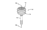
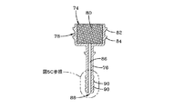
図5A、図5B、図5Cを参照すると、細長い円筒形の吸気導管76が、より大きな直径を有するフィルタ設置チャンバ74に一体的に連結されている。チャンバ74は、円筒形のフィルタハウジング78によって画定されている。ハウジング78には、円筒形の多孔質フィルタ部材80が収容されている。細長い管状の吸気導管76は、中心軸の空気通路86を有している。環状の保持フランジ82,84が、ハウジング78の周囲を延びている。吸気導管76の遠位連結端部88には、導管76の遠位端に向かって内側に先細になる一連の円錐台形の環状連結リブ90が設けられている。多孔質フィルタ部材80が設置された外側のフィルタチャンバ74には、通路86が連通している。吸気導管76のフィルタ外端部は、タイヤの外側の空気と連通するように配置され、ポンプシステムへの空気の取り入れ口として機能する。吸気導管76は、以下に説明するように、タイヤのインナーライナー領域に外気を送っている。したがって、吸気導管76の軸方向長さは、フィルタ部材80からタイヤサイドウォール16を通過してタイヤインナーライナー26に到達するのに十分な長さである。キャップ部材79が、フィルタハウジング78を包囲して、フィルタ部材80を内部に保持している。
Referring to FIGS. 5A, 5B, and 5C, an elongated
図6A、図6B、図6Cには、入口ハウジング92が示されている。ハウジング92は、細長い側壁94,96と上壁98と底壁100とを有する概ね長方形のブロック形状を有している。必要に応じて、ハウジング92を構成するために他の幾何形状を用いることができる。互いに離れて位置する一対の迅速継手式入口ソケット102,104が、ハウジング92によって一体的に形成され、底壁100内に延びている。ソケット102,104は細長く、概ね円筒形の内部構造を有している。ソケット102,104は、入口ハウジングの内部空気チャンバ(図示せず)への空気通路を形成している。ソケット102,104の内部長さに沿って、円錐台形状を有する一連の環状の戻り止めが配置されている。外部からアクセス可能な圧力設定ナットおよびボルト18が、ハウジング92内に延びている。底壁100に沿って、外側に突出する一連の尾根部110が設けられ、尾根部110は、ハウジング92をタイヤインナーライナー26に取り付けるために用いられる接着コーティング(図示せず)の接着を補助するように作動する。
An
ここでいう「入口ハウジング」は、流入空気を受け入れるハウジングとしての最も広い意味での総称として用いられる。ハウジング92は、吸気導管76から空気を受け取り、それを空気ポンプチューブ34に送り込む。ポンプチューブ34は、タイヤの全回転または部分回転ごとに空気を順次加圧する。総称的に「入口ハウジング」と称しているが、入口ハウジング92は、好ましい実施形態では、流入空気を受け入れるだけでなく、タイヤキャビティ28内の空気圧を制御する弁レギュレータシステムを含むハウジングとして特に用いられている。タイヤキャビティ28内の空気圧が閾値圧力にあるときには、ハウジング92内のレギュレータが閉じて、余分な加圧空気がタイヤキャビティに入るのを防いでいる。タイヤキャビティ28内の空気圧が閾値を下回るときには、ハウジング92内のレギュレータが開いて、加圧空気をタイヤキャビティへと導入することができる。
Here, the “inlet housing” is used as a general term in the broadest sense as a housing that receives incoming air. The
一般に、適切なレギュレータ弁システムは、タイヤキャビティの空気圧を測定するように作動する圧力測定機構を含んでいる。測定されたキャビティの空気圧は、その後、空気チューブ34からタイヤキャビティ28への空気の流れを開閉するために用いられる。ここで対象となる空気維持タイヤシステムに有効である、代表的な適切な2ポート弁システムが、その全体が参照により本明細書に組み込まれる2013年9月30日出願の同時係属の米国特許出願第14/041490号に見られている。開示されている2ポートシステムでは、吸気は、吸気導管76からソケット104を経由して入口ハウジング92へと導かれることになる。ハウジング92内部の流入空気は、ソケット102および入口導管66から入口コネクタ38を通って、ポンプチューブ34の空気流路へと送られる。そして、空気は、空気チューブ34によって蠕動的に加圧される。タイヤキャビティ圧力を閾値まで上げるために空気が必要とされる場合には、加圧空気がタイヤキャビティへと送られる。測定されたキャビティ圧力が閾値にあれば、加圧空気はポンプチューブ34から排気される。
In general, a suitable regulator valve system includes a pressure measurement mechanism that operates to measure the tire cavity air pressure. The measured cavity air pressure is then used to open and close the air flow from the
図6Cおよび図8に最もよく見られるように、ソケット102,104のそれぞれは、ハウジングによって一体的に形成され、細長い円筒形の内部構造を有している。ソケット102,104を通る空気通路は、ハウジング92内部の空気チャンバに連通している。さらに、ソケット102,104は、各ソケットを規定する円筒形の側壁に形成された、互いに離れて位置する一連の円錐台形の戻り止め106をそれぞれが有するように、ハウジング92によって形成されている。ソケット104,102内の戻り止め106の配置、形状、および寸法は、吸気導管の円錐台形の環状リブ90および入口導管の円錐台形の環状リブ72とそれぞれスナップ係合で嵌合しやすくするようになっている。したがって、導管70,88は、簡便かつ迅速にレギュレータハウジング92の各ソケットにスナップ式に取り付けられる。そのため、ハウジング組立体または吸気口組立体または入口組立体の交換や修理が必要になった場合に、そのような交換や修理が円滑に行われる。さらに、スナップ組立体によって、レギュレータ組立体をタイヤの内側に当接させてインナーライナー26に固定させることが可能になる。導管70,88の軸長は、タイヤサイドウォール16を通過して取り付けブラケット126の開口130,128を貫通して突出し、入口ハウジング92の各ソケット104,102に完全にスナップ式に挿入されるのに十分な長さである。
As best seen in FIGS. 6C and 8, each of the
図7Aから図7Cを参照すると、タイヤサイドウォール16の溝30への空気チューブ34の組み入れと、タイヤインナーライナー26への入口ハウジング92の取り付けとが示されている。空気チューブ34と入口コネクタ38の断面はそれぞれ、細長く、概ねマッシュルーム形状を有している。チューブ34の翼状突起114とコネクタ本体42の翼状突起46とは、サイドウォール溝30によって形成された部分の内部に保持されて設置されている。マッシュルーム構造は、その全体が参照により本明細書に組み込まれる2012年5月14日出願の同時係属の米国特許出願第13/470525号に詳細に示されている。ここで対象となる「マッシュルーム」構造では、蠕動チューブ34は、頂部を平面で切断したくさび形の車外側のチューブ本体112を含み、チューブ本体112は、外側に広がる側部によって形成され、側部は、狭い幅(D3)の平坦な端面118から車内側のドーム形の翼状突起114まで延び、各翼状突起114は、半径R1の上部のアーチ面と下部の平坦面とを有している。翼状突起114は、端壁(端面)から距離L4の位置にあり、チューブは、横断面L1の寸法を有している。くさび形の本体112の側部は、角度αで外側に広がり、翼状突起の裏面と交差している。チューブ34のキャップ領域は、内端部で平坦である。空気通路32は、楕円形であって、チューブ本体112の内部に位置し、チューブの断面中心線に沿った長手方向の主軸を有している。楕円形の通路の長さは、L2であり、その横方向幅は、D2である。D1は、チューブの先端から先端までの距離を示し、D3は、チューブの狭い端部の直径である。L3は、チューブ内の、端面から楕円形の通路196の中心までの距離である。
Referring to FIGS. 7A-7C, the incorporation of the
したがって、空気チューブ184は、以下に定める範囲、すなわち、
D1:6.39±0.1mm、
D2:0.7±0.01mm、
D3:1.44±0.05mm、
L1:4.25mm、
L2:2.2±0.1mm、
L3:1.78±0.01mm、
L4:1.83±0.05mm、
α:24°、
R1:1.85mm、
の範囲内の好ましい寸法を有している。
Accordingly, the air tube 184 has a range as defined below:
D1: 6.39 ± 0.1 mm,
D2: 0.7 ± 0.01 mm,
D3: 1.44 ± 0.05 mm,
L1: 4.25 mm,
L2: 2.2 ± 0.1 mm,
L3: 1.78 ± 0.01 mm,
L4: 1.83 ± 0.05 mm
α: 24 °
R1: 1.85 mm,
Preferred dimensions within the range of
入口コネクタ38は、空気チューブ34と相補的に構成され、相補的に構成された溝30を共有している。したがって、入口コネクタ38の断面は、概ね細長く、概ねマッシュルーム形状である。コネクタ38の翼状突起46が、インラインのコネクタ本体42から延びている。コネクタ38の本体42と翼状突起46は、溝30の内部にあって、コネクタ38を溝30の内部に保持して設置している。マッシュルーム構造は、同時係属の米国特許出願第13/470525号に詳細に示されている。この「マッシュルーム」構造では、チューブ34と同様に、入口コネクタ38は、頂部を平面で切断したくさび形の車外側のインライン本体部44を含み、インライン本体部44は、外側に広がる側部によって形成され、側部は、狭い幅(D3)の平坦な端面48から車内側のドーム形の翼状突起46まで延びている。各翼状突起46は、半径R1の上部のアーチ面と下部の平坦面とを有している。翼状突起46は、端壁(端面)から距離L4の位置にあり、チューブは、横断面L1の寸法を有している。くさび形のコネクタ本体部44の側部は、角度αで外側に広がり、翼状突起46の裏面と交差している。翼状突起46によって形成されたキャップ領域は、内端部で平坦である。マッシュルーム形状のコネクタ38の外形寸法は、空気チューブ34について前述した通りであり、サイドウォール16内の溝30の寸法および形状と相補的である。
The
図7Aから図7Dを参照すると、空気チューブ34と入口コネクタ38は、溝30に通じる狭い入口スリット116を通じて取り付けられる。空気チューブ34と入口コネクタ38は、弾性的に圧縮されて、スリット116を通じて進入することができる。溝30に入る際に、空気チューブ34と入口コネクタ38は、それぞれ共通のマッシュルーム形状へと曲がり、マッシュルーム形状の溝30の輪郭および幾何形状を満たすようになる。完全に挿入されると、入口コネクタの本体部44の先細端部における平坦面48と、空気チューブ本体112の先細の外側における平坦な端面118とは、タイヤサイドウォール16の外側と概ね同一平面上にあって、スリット116によって形成された開口を塞いでいる。貫通孔120が、サイドウォール16を貫通して形成され、外側の大口径のフィルタポケットつまりチャンバ124を含んでいる。貫通孔120は、フィルタ吸気部材40を密接に収容するような構成および寸法を有している。吸気導管76は、貫通孔120を貫通してタイヤインナーライナー26の側まで延びている。フィルタポケット124は、フィルタチャンバ74とフィルタ80とを収容している。
With reference to FIGS. 7A-7D, the
第2の貫通孔122が、従来の硬化後の製造手順によって、タイヤサイドウォール16を貫通して形成されている。貫通孔122は、入口コネクタ38の円筒形の入口導管66を収容するような大きさである。入口コネクタの導管66は、貫通孔122を貫通してタイヤサイドウォール16のインナーライナー26の側まで突出している。
The second through
図7B、図7C、図8に見られるように、吸気導管88と入口導管70は、ブラケットの各開口130,128を貫通して延びるのに十分な距離だけ、タイヤインナーライナー26からタイヤキャビティ28へと突出している。ブラケット126は、ゴム化合物などのエラストマー材料で形成されている。そして、吸気導管88と入口導管70は、入口ハウジング92のソケット104,102へと挿入されて、入口ハウジング92をブラケット126およびタイヤインナーライナー26に対して取り付けている。適切な接着剤を塗布して、ブラケット126およびハウジング92をタイヤインナーライナー26に固定的に接続することもできる。吸気導管88および入口導管70の軸をソケット104,102へと密接に挿入すると、その軸の端部に沿った環状のリブがソケット104,102内の環状の戻り止めに係合することによって、スナップ係合が達成される。これにより、吸気導管88を通って入口ハウジング92の中央空気チャンバへと至り、そこから入口コネクタ38を通って空気チューブ通路32へと至る空気経路が確立される。こうして、入口ハウジング92内のレギュレータ弁システムが、空気チューブ34への空気の流れを制御するとともに、空気チューブ34からタイヤキャビティへの加圧空気の流れを制御するように接続される。したがって、空気圧が、タイヤキャビティ内で所望の値に維持されることになる。
As seen in FIGS. 7B, 7C, and 8, the
上述したことから、それぞれマッシュルーム形状の空気チューブと入口コネクタの向きが、タイヤサイドウォール16内のマッシュルーム形状の溝の内部で一直線であることは明らかであろう。空気チューブおよび入口コネクタのマッシュルーム形状の輪郭は、一側部にあって、マッシュルーム構造の「キャップ」つまり翼状突起の側は、タイヤキャビティに向かって内側である。空気チューブおよび入口コネクタのマッシュルーム形状の「ステム」は、タイヤから離れてタイヤサイドウォール16の外面に向かう方向を向いている。このように向いているため、翼状突起は、空気チューブと入口コネクタをサイドウォール溝に閉じ込めて、タイヤからの望ましくない分離を防いでいる。吸気導管および入口導管は、タイヤサイドウォール16を貫通してインナーライナーに取り付けられた入口ハウジング92まで突出している。入口ハウジング92をタイヤキャビティの内部でタイヤインナーライナーに当接させることで、タイヤサイドウォール構造の構造的な乱れが最小になることが要求される。すなわち、入口ハウジング92が占める容積がタイヤサイドウォールの内部にではなくタイヤキャビティの容積に含まれるため、タイヤサイドウォールの構造的完全性に支障を来すことはない。吸気導管および入口導管を入口ハウジングのソケットに取り付けることで実現される迅速な接続および分離によって、効率的な組立手順の実現が可能になり、その一方で、構成部材の修理や交換が必要になった場合の分解が可能になる。
From the above, it will be clear that the orientation of the mushroom-shaped air tube and the inlet connector, respectively, is straight within the mushroom-shaped groove in the
本明細書に記載された本発明の説明を考慮すると、本発明の変形例が可能である。対象発明を説明する目的で、特定の代表的な実施形態および詳細が示されているが、対象発明の範囲から逸脱することなくさまざまな変更および修正が可能であることが、当業者には明らかであろう。したがって、記載された特定の実施形態において、添付の特許請求の範囲によって規定される本発明の対象となる全範囲内で行う変更が可能であることを理解されたい。 In light of the description of the invention described herein, variations of the invention are possible. For the purpose of illustrating the subject invention, certain representative embodiments and details are shown, but it will be apparent to those skilled in the art that various changes and modifications can be made without departing from the scope of the subject invention. Will. It is therefore to be understood that changes may be made in the particular embodiments described that are within the full scope of the invention as defined by the appended claims.
10 タイヤ組立体
12 タイヤ
16,18 サイドウォール
24 タイヤトレッド領域
26 インナーライナー
28 タイヤキャビティ
30 溝
32 空気通路
34 空気チューブ
44 コネクタ本体
50,52 空気チャンバ
66,70 入口導管
68 内部空気通路
72,90 リブ
76,88 吸気導管
92 入口ハウジング
102,104 ソケット
106 戻り止め
DESCRIPTION OF
Claims (13)
タイヤトレッド領域まで延びる第1および第2のサイドウォールによって境界が規定されたインナーライナーによって画定されたタイヤキャビティを有するタイヤと、
前記インナーライナーに固定された空気入口ハウジングと、を有し、
前記第1のサイドウォールが、該第1のサイドウォール内に細長いサイドウォール空気通路を有し、前記サイドウォール空気通路が、回転するタイヤの接地面から前記第1のサイドウォールへと伝わる曲げ歪みに応答して、拡大した直径から実質的に縮小した直径へとセグメントごとに圧縮され、それにより、該サイドウォール空気通路に沿ってセグメントごとに強制的に空気を送り込むように動作可能に配置され、
前記サイドウォール空気通路と前記入口ハウジングとの間に延びる細長い管状の入口導管であって、該入口導管の支柱が、前記入口ハウジングの内部から前記サイドウォール空気通路まで流入空気を送るように作動する内部空気通路を有する、入口導管と、
前記第1のサイドウォールを貫通して前記インナーライナーまで延び、前記空気入口ハウジングに連結されて、前記タイヤの外側からの空気を前記第1のサイドウォールを通って前記空気入口ハウジングへと送るように作動する吸気導管と、をさらに有し、
前記入口導管および前記吸気導管は、前記入口ハウジングによって形成された細長い第1および第2のソケットにそれぞれ係合し、それにより、前記入口ハウジングとの間で空気流が連通し、
前記入口導管および前記吸気導管と、前記第1および第2のソケットとは、それぞれ、相互係合式の戻り止め手段を有する、
ことを特徴とする空気維持タイヤ組立体。 An air maintenance tire assembly comprising:
A tire having a tire cavity defined by an innerliner delimited by first and second sidewalls extending to a tire tread region;
An air inlet housing fixed to the inner liner,
The first sidewall has an elongated sidewall air passage in the first sidewall, and the sidewall air passage is transmitted from the ground contact surface of the rotating tire to the first sidewall. In response to a compressed from segment to segment from an enlarged diameter to a substantially reduced diameter, thereby operatively arranged to force air into the segment along the sidewall air passage. ,
An elongated tubular inlet conduit extending between the sidewall air passage and the inlet housing, wherein the inlet conduit struts are operative to route incoming air from the interior of the inlet housing to the sidewall air passage. An inlet conduit having an internal air passage;
Extends through the first sidewall to the inner liner and is coupled to the air inlet housing to deliver air from outside the tire through the first sidewall to the air inlet housing. An intake conduit that operates on
The inlet conduit and the intake conduit engage respectively with elongated first and second sockets formed by the inlet housing, whereby air flow is in communication with the inlet housing;
Said inlet conduit and said air inlet conduit, and said first and second sockets, respectively, having a Ritome means back interengaging formula,
An air maintenance tire assembly characterized by the above.
タイヤトレッド領域まで延びる第1および第2のサイドウォールによって境界が規定されたインナーライナーによって画定されたタイヤキャビティを有するタイヤと、
前記インナーライナーに固定された空気入口ハウジングと、を有し、
前記第1のサイドウォールが、該第1のサイドウォール内に細長いサイドウォール空気通路を有し、前記サイドウォール空気通路が、回転するタイヤの接地面から前記第1のサイドウォールへと伝わる曲げ歪みに応答して、拡大した直径から実質的に縮小した直径へとセグメントごとに圧縮するように動作可能に配置され、それにより、該サイドウォール空気通路に沿ってセグメントごとに強制的に空気を送り込み、
前記サイドウォール空気通路と前記入口ハウジングとの間に延び、前記入口ハウジングの内部から前記サイドウォール空気通路までの流入空気を送るように作動する内部空気通路を有する細長い管状の入口導管であって、前記入口ハウジングによって形成された細長い第1のソケットへと軸方向に密接に挿入されることで前記入口ハウジングに取り付けられるとともに、前記第1のソケットから軸方向に引き抜かれることで前記入口ハウジングから取り外される入口導管と、
前記第1のサイドウォールを貫通して前記インナーライナーまで延び、前記空気入口ハウジングに連結されて、前記タイヤの外側からの空気を前記第1のサイドウォールを通って前記空気入口ハウジングへと送るように作動する吸気導管であって、前記入口ハウジングによって形成された細長い第2のソケットへと密接に挿入されることで前記入口ハウジングに取り付けられるとともに、前記第2のソケットから軸方向に引き抜かれることで前記入口ハウジングから取り外される吸気導管と、
をさらに有することを特徴とする空気維持タイヤ組立体。 An air maintenance tire assembly comprising:
A tire having a tire cavity defined by an innerliner delimited by first and second sidewalls extending to a tire tread region;
An air inlet housing fixed to the inner liner,
The first sidewall has an elongated sidewall air passage in the first sidewall, and the sidewall air passage is transmitted from the ground contact surface of the rotating tire to the first sidewall. Operatively arranged to compress segment by segment from an enlarged diameter to a substantially reduced diameter, thereby forcing air into the segment along the sidewall air passage ,
An elongate tubular inlet conduit having an internal air passage extending between the sidewall air passage and the inlet housing and operative to route incoming air from the interior of the inlet housing to the sidewall air passage; It is attached to the inlet housing by being axially closely inserted into an elongated first socket formed by the inlet housing, and is removed from the inlet housing by being pulled axially from the first socket. An inlet conduit,
Extends through the first sidewall to the inner liner and is coupled to the air inlet housing to deliver air from outside the tire through the first sidewall to the air inlet housing. An intake conduit that operates on the inlet housing and is attached to the inlet housing by being closely inserted into an elongated second socket formed by the inlet housing and is axially withdrawn from the second socket. An intake conduit removed from the inlet housing at
An air maintenance tire assembly further comprising:
タイヤキャビティの境界を規定するタイヤのインナーライナーに、圧力調整手段を含む空気入口ハウジングを固定することと、
前記タイヤの第1のサイドウォール内に細長いサイドウォール空気通路を配置することであって、回転するタイヤの接地面から前記第1のサイドウォールへと伝わる曲げ歪みに応答して、拡大した直径から実質的に縮小した直径へとセグメントごとに圧縮され、それにより、該サイドウォール空気通路に沿ってセグメントごとに強制的に空気を送り込むように動作可能な前記サイドウォール空気通路を配置することと、
前記第1のサイドウォールに、該第1のサイドウォールを貫通して前記入口ハウジングまで延びる吸気導管を取り付けることと、
前記入口ハウジングによって形成された細長い第1のソケットへと前記吸気導管を密接に挿入することで、前記入口ハウジングに前記吸気導管を嵌合させることと、
前記入口ハウジングによって形成された細長い第2のソケットへと入口導管を密接に挿入することで、前記入口ハウジングに前記入口導管を取り付けることと、
前記入口ハウジングからの流出空気を、前記入口導管を通って前記サイドウォール空気通路まで送ることと、
を含むことを特徴とする方法。 A method of assembling an air maintenance inlet assembly into a tire, comprising:
Fixing an air inlet housing including pressure regulating means to a tire inner liner defining a tire cavity boundary;
An elongated sidewall air passage is disposed within the first sidewall of the tire from an enlarged diameter in response to bending strain transmitted from the rotating tire's ground contact surface to the first sidewall. Disposing said sidewall air passages that are compressed segment by segment to a substantially reduced diameter, thereby operable to force air into each segment along the sidewall air passages;
Attaching an intake conduit extending through the first sidewall to the inlet housing to the first sidewall;
Fitting the intake conduit into the inlet housing by closely inserting the intake conduit into an elongated first socket formed by the inlet housing;
Attaching the inlet conduit to the inlet housing by intimately inserting the inlet conduit into an elongated second socket formed by the inlet housing;
Sending effluent air from the inlet housing through the inlet conduit to the sidewall air passageway;
A method comprising the steps of:
Applications Claiming Priority (2)
| Application Number | Priority Date | Filing Date | Title |
|---|---|---|---|
| US14/106,904 | 2013-12-16 | ||
| US14/106,904 US9205712B2 (en) | 2013-12-16 | 2013-12-16 | Snap-in inlet and connection method for air maintenance tire |
Publications (2)
| Publication Number | Publication Date |
|---|---|
| JP2015117014A JP2015117014A (en) | 2015-06-25 |
| JP6487689B2 true JP6487689B2 (en) | 2019-03-20 |
Family
ID=52021059
Family Applications (1)
| Application Number | Title | Priority Date | Filing Date |
|---|---|---|---|
| JP2014253747A Active JP6487689B2 (en) | 2013-12-16 | 2014-12-16 | Snap-in inlet and connection method for air maintenance tires |
Country Status (5)
| Country | Link |
|---|---|
| US (1) | US9205712B2 (en) |
| EP (1) | EP2889162B1 (en) |
| JP (1) | JP6487689B2 (en) |
| CN (1) | CN104709015B (en) |
| BR (1) | BR102014030803A2 (en) |
Families Citing this family (4)
| Publication number | Priority date | Publication date | Assignee | Title |
|---|---|---|---|---|
| US9421832B2 (en) * | 2013-02-04 | 2016-08-23 | The Goodyear Tire & Rubber Company | Air maintenance tire |
| US9604511B2 (en) * | 2015-08-11 | 2017-03-28 | The Goodyear Tire & Rubber Company | Air maintenance pumping assembly and tire |
| US9682599B1 (en) * | 2015-12-09 | 2017-06-20 | The Goodyear Tire & Rubber Company | On-wheel air maintenance system |
| JP2018083618A (en) * | 2016-11-23 | 2018-05-31 | ザ・グッドイヤー・タイヤ・アンド・ラバー・カンパニー | Mounting member for air maintenance tire |
Family Cites Families (30)
| Publication number | Priority date | Publication date | Assignee | Title |
|---|---|---|---|---|
| US1050886A (en) | 1910-02-23 | 1913-01-21 | Anson B Wetherell | Vehicle-tire. |
| US1134361A (en) | 1912-02-13 | 1915-04-06 | Anson B Wetherell | Self-filling tire. |
| GB1086512A (en) | 1964-02-24 | 1967-10-11 | Ronald Leslie Sheppard | Improvements in or relating to pneumatic tyres |
| US3867973A (en) | 1973-01-30 | 1975-02-25 | United Aircraft Prod | Pneumatic tire with embedded ring means |
| US3833041A (en) | 1973-10-11 | 1974-09-03 | Aerojet General Co | Tire inflator |
| DE3433318A1 (en) | 1984-09-11 | 1986-03-20 | Mousiol, Hans, 6000 Frankfurt | Method for inflating pneumatic tyres and pneumatic tyre for the method |
| FR2618102B1 (en) | 1987-07-15 | 1990-02-16 | Michelin & Cie | INFLATION OF A ROTATING TIRE |
| RU2106978C1 (en) | 1995-02-15 | 1998-03-20 | Леонид Михайлович Раткевич | Pneumatic tyre with automatic inflating device |
| AU2002361924A1 (en) | 2001-12-11 | 2003-06-23 | Frantisek Hrabal | Device for monitoring, maintenance and adjustment of pressure in a tyre |
| DE10335244A1 (en) | 2003-08-01 | 2005-03-10 | Bayerische Motoren Werke Ag | Device for air filling a rotating pneumatic tire |
| US7314072B2 (en) * | 2004-07-28 | 2008-01-01 | Grant Bunker | Integral pressure regulation system for tires and other vessels containing compressible fluids |
| CZ303718B6 (en) | 2006-05-23 | 2013-04-03 | Sithold S.R.O. | Retentivity component for adjusting pneumatic tyre pressure and process for producing thereof |
| SE532584C2 (en) | 2008-07-15 | 2010-02-23 | Jan Folke Wallenius | Vehicle tires with a valve assembly |
| US8186402B2 (en) * | 2009-03-24 | 2012-05-29 | Pressure Sentinel, Inc | Device for automatically maintaining tire pressure |
| US8381785B2 (en) * | 2010-05-07 | 2013-02-26 | The Goodyear Tire & Rubber Company | Self-inflating tire assembly |
| US8042586B2 (en) | 2009-12-21 | 2011-10-25 | The Goodyear Tire & Rubber Company | Self-inflating tire assembly |
| US8113254B2 (en) * | 2009-12-21 | 2012-02-14 | The Goodyear Tire & Rubber Company | Self-inflating tire |
| US8534335B2 (en) * | 2010-09-27 | 2013-09-17 | The Goodyear Tire & Rubber Company | Distributed pump self-inflating tire assembly |
| US8235081B2 (en) * | 2010-11-22 | 2012-08-07 | The Goodyear Tire & Rubber Company | In-line pumping assembly for self-inflating tire |
| EP2455240B1 (en) | 2010-11-22 | 2016-09-07 | The Goodyear Tire & Rubber Company | Method of manufacturing a self-inflating tire |
| US8550137B2 (en) * | 2010-11-22 | 2013-10-08 | The Goodyear Tire & Rubber Company | Tire for self-inflating tire system |
| US8695661B2 (en) * | 2011-07-15 | 2014-04-15 | The Goodyear Tire & Rubber Company | Air maintenance pumping tube and tire assembly |
| US8573270B2 (en) * | 2011-08-30 | 2013-11-05 | The Goodyear Tire & Rubber Company | Self-inflating tire and pressure regulator |
| US8851132B2 (en) | 2011-10-04 | 2014-10-07 | The Goodyear Tire & Rubber Company | Air maintenance tire and pumping tube assembly and method |
| US8820369B2 (en) * | 2011-11-09 | 2014-09-02 | The Goodyear Tire & Rubber Company | Self-inflating tire |
| US8875762B2 (en) * | 2011-12-21 | 2014-11-04 | The Goodyear Tire & Rubber Company | Air maintenance tire and elbow connector system |
| US8915277B2 (en) * | 2011-12-21 | 2014-12-23 | The Goodyear Tire & Rubber Company | Air maintenance tire and connector system |
| US9056533B2 (en) | 2012-05-14 | 2015-06-16 | The Goodyear Tire & Rubber Company | Peristaltic tube air maintenance tire assembly and method |
| US9045005B2 (en) * | 2012-12-06 | 2015-06-02 | The Goodyear Tire & Rubber Company | Air maintenance pumping assembly and tire |
| US9216620B2 (en) | 2013-12-16 | 2015-12-22 | The Goodyear Tire & Rubber Company | Peristaltic air pumping tube and tire assembly and method |
-
2013
- 2013-12-16 US US14/106,904 patent/US9205712B2/en active Active
-
2014
- 2014-12-09 BR BR102014030803A patent/BR102014030803A2/en not_active IP Right Cessation
- 2014-12-10 EP EP14197082.2A patent/EP2889162B1/en active Active
- 2014-12-16 CN CN201410774567.4A patent/CN104709015B/en active Active
- 2014-12-16 JP JP2014253747A patent/JP6487689B2/en active Active
Also Published As
| Publication number | Publication date |
|---|---|
| EP2889162B1 (en) | 2016-09-21 |
| JP2015117014A (en) | 2015-06-25 |
| EP2889162A2 (en) | 2015-07-01 |
| US20150165836A1 (en) | 2015-06-18 |
| US9205712B2 (en) | 2015-12-08 |
| CN104709015B (en) | 2017-03-15 |
| EP2889162A3 (en) | 2015-08-05 |
| BR102014030803A2 (en) | 2016-03-08 |
| CN104709015A (en) | 2015-06-17 |
Similar Documents
| Publication | Publication Date | Title |
|---|---|---|
| JP6487690B2 (en) | Peristaltic air pump tube and tire assembly and method | |
| US8573270B2 (en) | Self-inflating tire and pressure regulator | |
| KR101831451B1 (en) | In-line pumping assembly for self-inflating tire | |
| JP6463116B2 (en) | Bidirectional self-inflating tire with pressure regulator | |
| JP2014114010A (en) | Air maintenance pumping assembly and tire | |
| JP6487689B2 (en) | Snap-in inlet and connection method for air maintenance tires | |
| US9539869B2 (en) | Self-inflating tire and pressure regulator | |
| JP2015117016A (en) | Self-inflating tire equipped with pressure regulator | |
| JP2017095090A (en) | Air maintenance tire based on valve stem and method thereof | |
| US9327560B2 (en) | Compact valve system for self-inflating tire | |
| US9662944B2 (en) | Self inflating tire with pressure regulator | |
| JP2017036040A (en) | Valve stem base air maintenance tire and method | |
| US9233582B2 (en) | Self-inflating tire with inlet control valve | |
| EP2664467B1 (en) | Peristaltic tube air maintenance tire assembly | |
| CN108146156B (en) | Air maintenance tire and valve assembly and method | |
| US11285764B2 (en) | Control valve for an air maintenance tire | |
| US20150059952A1 (en) | Filter assembly for air maintenance tire | |
| US9604511B2 (en) | Air maintenance pumping assembly and tire | |
| US10023016B2 (en) | Outlet screw assembly for an air maintenance tire |
Legal Events
| Date | Code | Title | Description |
|---|---|---|---|
| A621 | Written request for application examination |
Free format text: JAPANESE INTERMEDIATE CODE: A621 Effective date: 20171030 |
|
| A977 | Report on retrieval |
Free format text: JAPANESE INTERMEDIATE CODE: A971007 Effective date: 20181010 |
|
| A131 | Notification of reasons for refusal |
Free format text: JAPANESE INTERMEDIATE CODE: A131 Effective date: 20181016 |
|
| A521 | Request for written amendment filed |
Free format text: JAPANESE INTERMEDIATE CODE: A523 Effective date: 20190108 |
|
| TRDD | Decision of grant or rejection written | ||
| A01 | Written decision to grant a patent or to grant a registration (utility model) |
Free format text: JAPANESE INTERMEDIATE CODE: A01 Effective date: 20190205 |
|
| A61 | First payment of annual fees (during grant procedure) |
Free format text: JAPANESE INTERMEDIATE CODE: A61 Effective date: 20190222 |
|
| R150 | Certificate of patent or registration of utility model |
Ref document number: 6487689 Country of ref document: JP Free format text: JAPANESE INTERMEDIATE CODE: R150 |
|
| R250 | Receipt of annual fees |
Free format text: JAPANESE INTERMEDIATE CODE: R250 |
|
| R250 | Receipt of annual fees |
Free format text: JAPANESE INTERMEDIATE CODE: R250 |
|
| R250 | Receipt of annual fees |
Free format text: JAPANESE INTERMEDIATE CODE: R250 |