US11385117B2 - Tire pressure monitoring module with thru-valve construction - Google Patents
Tire pressure monitoring module with thru-valve construction Download PDFInfo
- Publication number
- US11385117B2 US11385117B2 US16/778,739 US202016778739A US11385117B2 US 11385117 B2 US11385117 B2 US 11385117B2 US 202016778739 A US202016778739 A US 202016778739A US 11385117 B2 US11385117 B2 US 11385117B2
- Authority
- US
- United States
- Prior art keywords
- valve
- monitoring module
- sensor body
- arcuate
- tire monitoring
- Prior art date
- Legal status (The legal status is an assumption and is not a legal conclusion. Google has not performed a legal analysis and makes no representation as to the accuracy of the status listed.)
- Active, expires
Links
Images


Classifications
-
- B—PERFORMING OPERATIONS; TRANSPORTING
- B60—VEHICLES IN GENERAL
- B60C—VEHICLE TYRES; TYRE INFLATION; TYRE CHANGING; CONNECTING VALVES TO INFLATABLE ELASTIC BODIES IN GENERAL; DEVICES OR ARRANGEMENTS RELATED TO TYRES
- B60C23/00—Devices for measuring, signalling, controlling, or distributing tyre pressure or temperature, specially adapted for mounting on vehicles; Arrangement of tyre inflating devices on vehicles, e.g. of pumps or of tanks; Tyre cooling arrangements
- B60C23/02—Signalling devices actuated by tyre pressure
- B60C23/04—Signalling devices actuated by tyre pressure mounted on the wheel or tyre
- B60C23/0491—Constructional details of means for attaching the control device
- B60C23/0494—Valve stem attachments positioned inside the tyre chamber
-
- G—PHYSICS
- G01—MEASURING; TESTING
- G01L—MEASURING FORCE, STRESS, TORQUE, WORK, MECHANICAL POWER, MECHANICAL EFFICIENCY, OR FLUID PRESSURE
- G01L17/00—Devices or apparatus for measuring tyre pressure or the pressure in other inflated bodies
-
- B—PERFORMING OPERATIONS; TRANSPORTING
- B60—VEHICLES IN GENERAL
- B60C—VEHICLE TYRES; TYRE INFLATION; TYRE CHANGING; CONNECTING VALVES TO INFLATABLE ELASTIC BODIES IN GENERAL; DEVICES OR ARRANGEMENTS RELATED TO TYRES
- B60C23/00—Devices for measuring, signalling, controlling, or distributing tyre pressure or temperature, specially adapted for mounting on vehicles; Arrangement of tyre inflating devices on vehicles, e.g. of pumps or of tanks; Tyre cooling arrangements
- B60C23/02—Signalling devices actuated by tyre pressure
- B60C23/04—Signalling devices actuated by tyre pressure mounted on the wheel or tyre
- B60C23/0491—Constructional details of means for attaching the control device
- B60C23/0496—Valve stem attachments positioned outside of the tyre chamber
-
- B—PERFORMING OPERATIONS; TRANSPORTING
- B60—VEHICLES IN GENERAL
- B60C—VEHICLE TYRES; TYRE INFLATION; TYRE CHANGING; CONNECTING VALVES TO INFLATABLE ELASTIC BODIES IN GENERAL; DEVICES OR ARRANGEMENTS RELATED TO TYRES
- B60C29/00—Arrangements of tyre-inflating valves to tyres or rims; Accessories for tyre-inflating valves, not otherwise provided for
- B60C29/005—Arrangements of tyre-inflating valves to tyres or rims; Accessories for tyre-inflating valves, not otherwise provided for characterised by particular features of the valve stem
-
- B—PERFORMING OPERATIONS; TRANSPORTING
- B60—VEHICLES IN GENERAL
- B60C—VEHICLE TYRES; TYRE INFLATION; TYRE CHANGING; CONNECTING VALVES TO INFLATABLE ELASTIC BODIES IN GENERAL; DEVICES OR ARRANGEMENTS RELATED TO TYRES
- B60C29/00—Arrangements of tyre-inflating valves to tyres or rims; Accessories for tyre-inflating valves, not otherwise provided for
- B60C29/02—Connection to rims
Definitions
- the disclosure relates to a Tire Pressure Monitoring System (TPMS) module.
- TPMS Tire Pressure Monitoring System
- a TPMS module includes a housing within which a pressure measuring device and a transmission device are provided.
- the pressure measuring housing is attached to a tire valve and installed inside the tire to be monitored.
- the housing is shaped to be adjacent to, i.e., rest on, an interior rim well.
- the housing be adjacent the interior wheel rim well for reliability purposes.
- An issue arises, however, with respect to the differing geometries of the interior rim wells of various wheels and/or rims.
- the valve and rim/wheel geometries may combine to prevent the TPMS module from being able to contact the interior rim well.
- a bolt-in TPMS module must meet customer-specified residual torque specifications in order to resist sensor clocking and/or lift during high centrifugal loading.
- a known solution to the foregoing issues implements a variable angle TPMS sensor module that can adjust the angle of the module with respect to the wheel rim.
- a metal-to-metal contact bolt joint is typically used in order to resist the static and dynamic loads applied to the sensor during its time in service.
- a tire monitoring module comprising: a sensor body having an opening defined therein and receiving surfaces provided adjacent the opening; and a valve comprising: a distal portion; a coupling portion; a plurality of arcuate surfaces provided on the coupling portion; and a set of gripping structures disposed on coupling portion arcuate surface.
- the valve is provided in the sensor body opening and arranged such that the gripping structures couple to the sensor body arcuate receiving surfaces to maintain a fixed relationship of the valve to the sensor body.
- each set of gripping structures comprises a plurality of gripping teeth.
- each gripping tooth in the plurality of gripping teeth comprises a linear protrusion extending from the arcuate surface.
- the linear protrusions on the tab arcuate surfaces are parallel to one another and are equidistantly distributed.
- the gripping structures deform the sensor body arcuate receiving surfaces and engage therewith.
- a tire monitoring module comprising: a sensor body having an opening defined therein and two arcuate receiving surfaces provided adjacent the opening; a valve having a distal portion and a coupling portion; a plurality of opposed arcuate surfaces provided on the coupling portion; and a plurality of gripping teeth disposed on the arcuate surface.
- the valve is provided in the sensor body opening and arranged such that the gripping teeth on the coupling portion arcuate surfaces couple to the sensor body arcuate receiving surfaces.
- FIG. 1 is an exploded view of a TPMS module in accordance with an aspect of the present disclosure
- FIG. 2 is a perspective view of the TPMS module of FIG. 1 when assembled
- FIG. 3 is a perspective view of a valve component of the TPMS module in accordance with an aspect of the present disclosure
- FIG. 4 is a close-up perspective view of a portion of the valve component of FIG. 3 ;
- FIG. 5 is a top view of a seat component of the TPMS module in accordance with an aspect of the present disclosure
- FIG. 6 is a perspective view of a sensor body component of the TPMS module in accordance with an aspect of the present disclosure
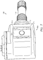
- FIG. 7 is a perspective view of the TPMS module of FIG. 1 taken from the direction V as shown in FIG. 2 ;
- FIG. 8 is a partially transparent perspective view of the TPMS module of FIG. 2 .
- One known TPMS with a variable angle module includes a metal insert embedded within a polymer enclosure.
- the use of such an insert increases the part count which, in turn, increases the unit cost and the manufacturing complexity.
- aspects of the present disclosure provide for, among other aspects, a TPMS module with mounting features that are adjustable through a wide range of angles.
- a TPMS module with mounting features that are adjustable through a wide range of angles.
- an insert component there is no need for an insert component, as in known systems and, therefore, complexity and cost are reduced.
- aspects of the present disclosure include a valve design that loads directly onto the seat that contains a seal/grommet structure.
- a sensor housing can be positioned on an extensive range of wheel rim/valve combinations because of the presence of a “toothed geometry” that will grip the enclosure and hold it in place, effectively resisting centrifugal forces to which it is subjected.
- FIG. 1 there is presented an exploded view of a TPMS module 100 , in accordance with one aspect of the present disclosure, that includes a sensor body 105 and a valve 110 .
- the sensor body 105 includes circuitry and devices for measuring tire characteristics such as pressure, temperature and the like and for transmitting those measurements and is made of, in one non-limiting example, plastic nylon.
- the valve 110 is made of aluminum, similar to known valves, and provides a fluid connection for filling a tire, for example, with air.
- the valve 110 includes a valve stem portion 115 at a distal end and a coupling portion 120 at a proximal end. The structure of the coupling portion 120 will be described below in more detail.
- the valve stem portion 115 is positioned in an opening 125 of the sensor body 105 , as shown.
- a seat 130 and a grommet 135 are then positioned to couple the valve 110 to the sensor body 105 .
- the grommet 135 is press-fit or stretched around the valve 110 into the seat 130 to hold the assembly together as is shown in FIG. 2 .
- the grommet 135 and the seat 130 can be separated from one another if necessary. Further, in an alternative embodiment of the present disclosure, the grommet 135 can be overmolded around the valve and into the seat 130 .
- the coupling portion 120 includes, for example, two portions 310 - 1 , 310 - 2 , that extend perpendicularly from the valve 110 with respect to a longitudinal axis of the valve 110 , as shown in FIGS. 3 and 4 .
- Each portion 310 - 1 , 310 - 2 comprises a respective arcuate surface 315 - 1 , 315 - 2 .
- the portions 310 - 1 , 310 - 2 may, in one embodiment of the present disclosure, be integrally formed with the coupling portion 120 .
- a plurality of gripping structures 320 are disposed on, and extend from, each arcuate surface 315 - x .
- the gripping structures 320 are teeth 320 that are operative as grippers and, in one aspect of the present disclosure, the teeth 320 are linear and arranged parallel to one another.
- the teeth 320 are evenly, i.e., equidistantly, distributed or positioned across the arcuate surface 315 although they need not be so positioned.
- a plurality of teeth 320 is shown effectively covering an entire area of the arcuate surface 315 , one of ordinary skill in the art will understand that the teeth 320 can be provided on less than all of the area of the arcuate surface 315 .
- a collar surface 330 is provided adjacent the portions 310 - 1 , 310 - 2 .
- the collar surface 330 is configured to couple to the collar 130 and includes two keys 335 - 1 , 335 - 2 .
- the collar surface 330 transfers an axial load that is created when a the grommet 135 is installed. The axial load is transferred from the nut to the surface 330 through the seat 130 and to the valve and reduces the risk of material creep.
- an opening 505 is defined therein.
- a perimeter of the opening 505 includes two notches 510 - 1 , 510 - 2 that are configured, i.e., arranged, to couple to the two keys 335 - 1 , 335 - 2 , respectively.
- the seat 130 is configured to couple to the collar surface 330 in a predetermined arrangement.
- the keys 335 - 1 , 335 - 2 are not provided and the seat 130 then does not include the notches 510 - 1 , 510 - 2 . Still further, only one key 335 and one respective notch 510 may be provided.
- the sensor body 105 includes two receiving surfaces 605 - 1 , 605 - 2 adjacent the opening 125 as shown in FIG. 6 , a view of the sensor body 105 from a direction V as shown in FIG. 2 .
- the two receiving surfaces 605 - 1 , 605 - 2 are symmetrically disposed about the opening 125 .
- Each of the receiving surfaces 605 - 1 , 605 - 2 has an arcuate shape that corresponds to the shape of the arcuate surfaces 315 - 1 , 315 - 2 on the coupling portion 120 .
- the valve 110 is positioned through the opening 125 and an angle of the valve with respect to the sensor body 105 is set.
- the teeth 320 will bite into, i.e., deforms or displaces the receiving surfaces, in order to engage with the receiving surfaces 605 - 1 , 605 - 2 to maintain the orientation of the valve 110 to the sensor body 105 when installed in a tire rim, as shown in FIGS. 7 and 8 .
Abstract
Description
Claims (20)
Priority Applications (4)
| Application Number | Priority Date | Filing Date | Title |
|---|---|---|---|
| US16/778,739 US11385117B2 (en) | 2020-01-31 | 2020-01-31 | Tire pressure monitoring module with thru-valve construction |
| CN202080095310.XA CN115052760A (en) | 2020-01-31 | 2020-12-03 | Tire pressure monitoring module with through air valve structure |
| PCT/US2020/063122 WO2021154387A1 (en) | 2020-01-31 | 2020-12-03 | Tire pressure monitoring module with thru-valve construction |
| EP20828224.4A EP4076998A1 (en) | 2020-01-31 | 2020-12-03 | Tire pressure monitoring module with thru-valve construction |
Applications Claiming Priority (1)
| Application Number | Priority Date | Filing Date | Title |
|---|---|---|---|
| US16/778,739 US11385117B2 (en) | 2020-01-31 | 2020-01-31 | Tire pressure monitoring module with thru-valve construction |
Publications (2)
| Publication Number | Publication Date |
|---|---|
| US20210239558A1 US20210239558A1 (en) | 2021-08-05 |
| US11385117B2 true US11385117B2 (en) | 2022-07-12 |
Family
ID=73855583
Family Applications (1)
| Application Number | Title | Priority Date | Filing Date |
|---|---|---|---|
| US16/778,739 Active 2040-06-24 US11385117B2 (en) | 2020-01-31 | 2020-01-31 | Tire pressure monitoring module with thru-valve construction |
Country Status (4)
| Country | Link |
|---|---|
| US (1) | US11385117B2 (en) |
| EP (1) | EP4076998A1 (en) |
| CN (1) | CN115052760A (en) |
| WO (1) | WO2021154387A1 (en) |
Families Citing this family (2)
| Publication number | Priority date | Publication date | Assignee | Title |
|---|---|---|---|---|
| KR20230042203A (en) * | 2021-09-15 | 2023-03-28 | 다이헤이요고교 가부시키가이샤 | tire valve |
| TWI828200B (en) * | 2022-06-21 | 2024-01-01 | 系統電子工業股份有限公司 | Improved tire pressure detector fixed structure |
Citations (29)
| Publication number | Priority date | Publication date | Assignee | Title |
|---|---|---|---|---|
| US20030066343A1 (en) | 2001-10-04 | 2003-04-10 | Martin Fischer | Device for measuring a tire pressure |
| US6546982B1 (en) | 1998-08-03 | 2003-04-15 | The Goodyear Tire & Rubber Company | Mounting transponders in pneumatic tires |
| US20030079537A1 (en) * | 2001-10-29 | 2003-05-01 | Siemens Vdo Automotive | Pressure sensor intended to be mounted in a tire, and support therefor |
| EP1433625A1 (en) | 2002-12-24 | 2004-06-30 | Pacific Industrial Co., Ltd. | Transmitter in tire condition monitoring apparatus |
| US6805001B2 (en) * | 2001-08-16 | 2004-10-19 | Siemens Vdo Automotive | Pressure detector adapted to be mounted in a tire |
| US20040261510A1 (en) | 2003-04-04 | 2004-12-30 | Schulze Gunther Lothar | Device for detecting and signaling a physical value when connected to a rim, and rim comprising such a device |
| US20050087007A1 (en) * | 2003-10-24 | 2005-04-28 | Lear Corporation | Tire monitor system with spring retention clip |
| US20050132792A1 (en) | 2003-12-19 | 2005-06-23 | Lemense Thomas J. | Tire pressure monitoring system |
| US7021133B1 (en) | 2005-06-16 | 2006-04-04 | Lite-On Automotive Corp. | Tire condition sensing apparatus and mounting method thereof |
| DE202007009443U1 (en) | 2006-12-04 | 2007-09-13 | Shanghai Baolong Industries Corporation, Dongjing | Signal housing unit for a stepwise adjustable tire pressure sensor |
| US20070257666A1 (en) | 2004-08-10 | 2007-11-08 | Frederic Laure | Method And Device For The Detection Of The Separation Of An Electronic Module From A Vehicle To Which It Is Mounted |
| US20070295076A1 (en) | 2006-06-21 | 2007-12-27 | Trw Automotive U.S. Llc | Tire pressure monitoring apparatus |
| FR2907048A1 (en) | 2006-10-16 | 2008-04-18 | Siemens Vdo Automotive Sas | Electronic unit for e.g. pressure measurement, in motor vehicle wheel, has insert and return to delimit housing directly receiving head, where insert is formed of metal plate to support locking face, and has indentation for passage of body |
| WO2008055944A1 (en) * | 2006-11-09 | 2008-05-15 | Société de Technologie Michelin | Tyre valve fixing element |
| US20080276995A1 (en) * | 2007-05-09 | 2008-11-13 | Lv Sensors, Inc. | Monitoring device attachment to rubber valve stems |
| WO2010114187A1 (en) * | 2009-04-01 | 2010-10-07 | 씨트론 주식회사 | Tire pressure monitoring system and tire sensor thereof |
| US8234919B2 (en) | 2008-01-24 | 2012-08-07 | Borgwarner Beru Systems Gmbh | Tire pressure control system |
| US20130233399A1 (en) * | 2012-03-09 | 2013-09-12 | Nissan North America, Inc. | Valve stem grommet structure |
| WO2014108926A1 (en) * | 2013-01-09 | 2014-07-17 | Wonder Spa | Metal valve of the clamp-in type for inflating tyres associable with a tpms transducer |
| EP2777958A1 (en) | 2013-03-15 | 2014-09-17 | The Goodyear Tire & Rubber Company | An encasing for releasably containing a device and tire containing such encasing or encased device |
| US20140352420A1 (en) | 2011-12-29 | 2014-12-04 | Pirelli Tyre S.P.A. | Monitoring device for tyres for vehicle wheels, tyre for vehicle wheels provided with said monitoring device, and method for installing an electronic unit in said tyre |
| WO2017150396A1 (en) | 2016-03-02 | 2017-09-08 | 株式会社ブリヂストン | Functional component attachment member |
| US20170284786A1 (en) | 2016-03-30 | 2017-10-05 | Ford Global Technologies, Llc | Methods for positioning rechargeable tire pressure monitoring sensors |
| CN107433827A (en) | 2016-05-27 | 2017-12-05 | 上海北京大学微电子研究院 | Tire pressure senses transmitter module mounting structure |
| WO2018122924A1 (en) * | 2016-12-26 | 2018-07-05 | 太平洋工業 株式会社 | Tire condition detecting apparatus, clamp-in valve and tire valve unit |
| US20180333997A1 (en) * | 2017-05-17 | 2018-11-22 | Orange Seal | Configurable valve stem assembly |
| US20190217672A1 (en) | 2016-07-18 | 2019-07-18 | Baolong Huf Shanghai Electronic Co., Ltd. | Connection structure between tire pressure monitoring sensor and tire valve |
| US20200254831A1 (en) * | 2016-12-26 | 2020-08-13 | Pacific Industrial Co., Ltd. | Tire condition detecting device |
| EP3865319A1 (en) * | 2020-02-14 | 2021-08-18 | Continental Automotive GmbH | Valve system, tyre parameter monitoring system and method for mounting a tyre parameter monitoring system onto a wheel rim of a vehicle |
-
2020
- 2020-01-31 US US16/778,739 patent/US11385117B2/en active Active
- 2020-12-03 CN CN202080095310.XA patent/CN115052760A/en active Pending
- 2020-12-03 EP EP20828224.4A patent/EP4076998A1/en active Pending
- 2020-12-03 WO PCT/US2020/063122 patent/WO2021154387A1/en unknown
Patent Citations (30)
| Publication number | Priority date | Publication date | Assignee | Title |
|---|---|---|---|---|
| US6546982B1 (en) | 1998-08-03 | 2003-04-15 | The Goodyear Tire & Rubber Company | Mounting transponders in pneumatic tires |
| US6805001B2 (en) * | 2001-08-16 | 2004-10-19 | Siemens Vdo Automotive | Pressure detector adapted to be mounted in a tire |
| US20030066343A1 (en) | 2001-10-04 | 2003-04-10 | Martin Fischer | Device for measuring a tire pressure |
| US20030079537A1 (en) * | 2001-10-29 | 2003-05-01 | Siemens Vdo Automotive | Pressure sensor intended to be mounted in a tire, and support therefor |
| EP1433625A1 (en) | 2002-12-24 | 2004-06-30 | Pacific Industrial Co., Ltd. | Transmitter in tire condition monitoring apparatus |
| US20040261510A1 (en) | 2003-04-04 | 2004-12-30 | Schulze Gunther Lothar | Device for detecting and signaling a physical value when connected to a rim, and rim comprising such a device |
| US20050087007A1 (en) * | 2003-10-24 | 2005-04-28 | Lear Corporation | Tire monitor system with spring retention clip |
| US20050132792A1 (en) | 2003-12-19 | 2005-06-23 | Lemense Thomas J. | Tire pressure monitoring system |
| US20070257666A1 (en) | 2004-08-10 | 2007-11-08 | Frederic Laure | Method And Device For The Detection Of The Separation Of An Electronic Module From A Vehicle To Which It Is Mounted |
| US7021133B1 (en) | 2005-06-16 | 2006-04-04 | Lite-On Automotive Corp. | Tire condition sensing apparatus and mounting method thereof |
| US20070295076A1 (en) | 2006-06-21 | 2007-12-27 | Trw Automotive U.S. Llc | Tire pressure monitoring apparatus |
| FR2907048A1 (en) | 2006-10-16 | 2008-04-18 | Siemens Vdo Automotive Sas | Electronic unit for e.g. pressure measurement, in motor vehicle wheel, has insert and return to delimit housing directly receiving head, where insert is formed of metal plate to support locking face, and has indentation for passage of body |
| WO2008055944A1 (en) * | 2006-11-09 | 2008-05-15 | Société de Technologie Michelin | Tyre valve fixing element |
| DE202007009443U1 (en) | 2006-12-04 | 2007-09-13 | Shanghai Baolong Industries Corporation, Dongjing | Signal housing unit for a stepwise adjustable tire pressure sensor |
| US20080276995A1 (en) * | 2007-05-09 | 2008-11-13 | Lv Sensors, Inc. | Monitoring device attachment to rubber valve stems |
| US8234919B2 (en) | 2008-01-24 | 2012-08-07 | Borgwarner Beru Systems Gmbh | Tire pressure control system |
| WO2010114187A1 (en) * | 2009-04-01 | 2010-10-07 | 씨트론 주식회사 | Tire pressure monitoring system and tire sensor thereof |
| US20140352420A1 (en) | 2011-12-29 | 2014-12-04 | Pirelli Tyre S.P.A. | Monitoring device for tyres for vehicle wheels, tyre for vehicle wheels provided with said monitoring device, and method for installing an electronic unit in said tyre |
| US20130233399A1 (en) * | 2012-03-09 | 2013-09-12 | Nissan North America, Inc. | Valve stem grommet structure |
| US20150343861A1 (en) * | 2013-01-09 | 2015-12-03 | Wonder Spa | Metal valve of the clamp-in type for inflating tyres associable with a tpms transducer |
| WO2014108926A1 (en) * | 2013-01-09 | 2014-07-17 | Wonder Spa | Metal valve of the clamp-in type for inflating tyres associable with a tpms transducer |
| EP2777958A1 (en) | 2013-03-15 | 2014-09-17 | The Goodyear Tire & Rubber Company | An encasing for releasably containing a device and tire containing such encasing or encased device |
| WO2017150396A1 (en) | 2016-03-02 | 2017-09-08 | 株式会社ブリヂストン | Functional component attachment member |
| US20170284786A1 (en) | 2016-03-30 | 2017-10-05 | Ford Global Technologies, Llc | Methods for positioning rechargeable tire pressure monitoring sensors |
| CN107433827A (en) | 2016-05-27 | 2017-12-05 | 上海北京大学微电子研究院 | Tire pressure senses transmitter module mounting structure |
| US20190217672A1 (en) | 2016-07-18 | 2019-07-18 | Baolong Huf Shanghai Electronic Co., Ltd. | Connection structure between tire pressure monitoring sensor and tire valve |
| WO2018122924A1 (en) * | 2016-12-26 | 2018-07-05 | 太平洋工業 株式会社 | Tire condition detecting apparatus, clamp-in valve and tire valve unit |
| US20200254831A1 (en) * | 2016-12-26 | 2020-08-13 | Pacific Industrial Co., Ltd. | Tire condition detecting device |
| US20180333997A1 (en) * | 2017-05-17 | 2018-11-22 | Orange Seal | Configurable valve stem assembly |
| EP3865319A1 (en) * | 2020-02-14 | 2021-08-18 | Continental Automotive GmbH | Valve system, tyre parameter monitoring system and method for mounting a tyre parameter monitoring system onto a wheel rim of a vehicle |
Non-Patent Citations (2)
| Title |
|---|
| Great Britain International Search Report for Application No. GB1910564.2; dated Jan. 15, 2020; 3 pages. |
| International Search Report & Written Opinion, PCT/US2020/063122, dated Feb. 11, 2021, 11 pages. |
Also Published As
| Publication number | Publication date |
|---|---|
| WO2021154387A1 (en) | 2021-08-05 |
| EP4076998A1 (en) | 2022-10-26 |
| US20210239558A1 (en) | 2021-08-05 |
| CN115052760A (en) | 2022-09-13 |
Similar Documents
| Publication | Publication Date | Title |
|---|---|---|
| US11385117B2 (en) | Tire pressure monitoring module with thru-valve construction | |
| KR20060053220A (en) | Assembly for attaching a detection unit, in particular for detecting tyre pressure, to a rim | |
| US10316978B2 (en) | Tire valve unit | |
| JP7155416B2 (en) | ADAPTER, TIRE PARAMETER MONITORING SYSTEM AND METHOD FOR MOUNTING TIRE PARAMETER MONITORING SYSTEM ON WHEEL RIM | |
| US9417158B2 (en) | Electronic unit for measuring operating parameters of a vehicle wheel, comprising an electronic module and an inflation valve | |
| US7726370B2 (en) | Vehicle wheel comprising a wheel rim and rubber tire | |
| US20110272038A1 (en) | Adapter incorporating TPMS onto a truck valve | |
| EP1496274A1 (en) | Fast locking element | |
| EP3366498B1 (en) | Tire-state detection device | |
| EP3450222B1 (en) | Tire condition detecting apparatus, clamp-in valve and tire valve unit | |
| MXPA96002086A (en) | Stabilized hose accessory paraacoplamie | |
| US11724553B2 (en) | Valve system, tire parameter monitoring system and method for mounting a tire parameter monitoring system onto a wheel rim of a vehicle | |
| US11602958B2 (en) | Adapter, valve stem, tire parameter monitoring system, and method of mounting a tire parameter monitoring system onto a wheel rim | |
| EP3260312A1 (en) | Air maintenance tire system comprising a component protector | |
| US11897296B2 (en) | Ball and socket articulating TPM sensor | |
| US20230158831A1 (en) | Wheel-internal double beadlock system and methods thereof | |
| US11970029B2 (en) | Adapter, tyre parameter monitoring system and method for mounting a tyre parameter monitoring system onto a wheel rim | |
| WO2022249264A1 (en) | Tire valve | |
| US20080184786A1 (en) | Wheel sensor with valve |
Legal Events
| Date | Code | Title | Description |
|---|---|---|---|
| FEPP | Fee payment procedure |
Free format text: ENTITY STATUS SET TO UNDISCOUNTED (ORIGINAL EVENT CODE: BIG.); ENTITY STATUS OF PATENT OWNER: LARGE ENTITY |
|
| STPP | Information on status: patent application and granting procedure in general |
Free format text: DOCKETED NEW CASE - READY FOR EXAMINATION |
|
| AS | Assignment |
Owner name: SENSATA TECHNOLOGIES, INC., MASSACHUSETTS Free format text: ASSIGNMENT OF ASSIGNORS INTEREST;ASSIGNOR:STORRIE, RYAN;REEL/FRAME:053561/0237 Effective date: 20200318 |
|
| STPP | Information on status: patent application and granting procedure in general |
Free format text: NON FINAL ACTION MAILED |
|
| STPP | Information on status: patent application and granting procedure in general |
Free format text: RESPONSE TO NON-FINAL OFFICE ACTION ENTERED AND FORWARDED TO EXAMINER |
|
| STPP | Information on status: patent application and granting procedure in general |
Free format text: FINAL REJECTION MAILED |
|
| STPP | Information on status: patent application and granting procedure in general |
Free format text: RESPONSE AFTER FINAL ACTION FORWARDED TO EXAMINER |
|
| STPP | Information on status: patent application and granting procedure in general |
Free format text: NOTICE OF ALLOWANCE MAILED -- APPLICATION RECEIVED IN OFFICE OF PUBLICATIONS |
|
| STCF | Information on status: patent grant |
Free format text: PATENTED CASE |