US7726370B2 - Vehicle wheel comprising a wheel rim and rubber tire - Google Patents
Vehicle wheel comprising a wheel rim and rubber tire Download PDFInfo
- Publication number
- US7726370B2 US7726370B2 US11/569,143 US56914306A US7726370B2 US 7726370 B2 US7726370 B2 US 7726370B2 US 56914306 A US56914306 A US 56914306A US 7726370 B2 US7726370 B2 US 7726370B2
- Authority
- US
- United States
- Prior art keywords
- annular
- shell
- segments
- upper shell
- vehicle wheel
- Prior art date
- Legal status (The legal status is an assumption and is not a legal conclusion. Google has not performed a legal analysis and makes no representation as to the accuracy of the status listed.)
- Expired - Fee Related, expires
Links
- 239000005060 rubber Substances 0.000 title description 5
- 239000007787 solid Substances 0.000 claims abstract description 30
- 238000004073 vulcanization Methods 0.000 claims description 5
- 125000006850 spacer group Chemical group 0.000 claims description 2
- 238000000034 method Methods 0.000 claims 5
- 230000008878 coupling Effects 0.000 claims 4
- 238000010168 coupling process Methods 0.000 claims 4
- 238000005859 coupling reaction Methods 0.000 claims 4
- 239000004033 plastic Substances 0.000 description 5
- 229920003023 plastic Polymers 0.000 description 5
- 230000006835 compression Effects 0.000 description 4
- 238000007906 compression Methods 0.000 description 4
- 238000010276 construction Methods 0.000 description 4
- 239000004952 Polyamide Substances 0.000 description 2
- 239000007769 metal material Substances 0.000 description 2
- 229920002647 polyamide Polymers 0.000 description 2
- 230000003068 static effect Effects 0.000 description 2
- HCHKCACWOHOZIP-UHFFFAOYSA-N Zinc Chemical compound [Zn] HCHKCACWOHOZIP-UHFFFAOYSA-N 0.000 description 1
- 230000001133 acceleration Effects 0.000 description 1
- 229910052782 aluminium Inorganic materials 0.000 description 1
- XAGFODPZIPBFFR-UHFFFAOYSA-N aluminium Chemical compound [Al] XAGFODPZIPBFFR-UHFFFAOYSA-N 0.000 description 1
- 239000006229 carbon black Substances 0.000 description 1
- 238000004140 cleaning Methods 0.000 description 1
- 238000004512 die casting Methods 0.000 description 1
- 239000011152 fibreglass Substances 0.000 description 1
- 230000013011 mating Effects 0.000 description 1
- 229910052751 metal Inorganic materials 0.000 description 1
- 239000002184 metal Substances 0.000 description 1
- 238000000926 separation method Methods 0.000 description 1
- 229910052725 zinc Inorganic materials 0.000 description 1
- 239000011701 zinc Substances 0.000 description 1
Images


Classifications
-
- B—PERFORMING OPERATIONS; TRANSPORTING
- B60—VEHICLES IN GENERAL
- B60C—VEHICLE TYRES; TYRE INFLATION; TYRE CHANGING; CONNECTING VALVES TO INFLATABLE ELASTIC BODIES IN GENERAL; DEVICES OR ARRANGEMENTS RELATED TO TYRES
- B60C7/00—Non-inflatable or solid tyres
- B60C7/24—Non-inflatable or solid tyres characterised by means for securing tyres on rim or wheel body
-
- B—PERFORMING OPERATIONS; TRANSPORTING
- B60—VEHICLES IN GENERAL
- B60B—VEHICLE WHEELS; CASTORS; AXLES FOR WHEELS OR CASTORS; INCREASING WHEEL ADHESION
- B60B25/00—Rims built-up of several main parts ; Locking means for the rim parts
- B60B25/02—Segmented rims, e.g. with segments arranged in sections; Connecting equipment, e.g. hinges; Insertable flange rings therefor
-
- B—PERFORMING OPERATIONS; TRANSPORTING
- B60—VEHICLES IN GENERAL
- B60B—VEHICLE WHEELS; CASTORS; AXLES FOR WHEELS OR CASTORS; INCREASING WHEEL ADHESION
- B60B25/00—Rims built-up of several main parts ; Locking means for the rim parts
- B60B25/22—Other apurtenances, e.g. for sealing the component parts enabling the use of tubeless tyres
-
- B—PERFORMING OPERATIONS; TRANSPORTING
- B60—VEHICLES IN GENERAL
- B60B—VEHICLE WHEELS; CASTORS; AXLES FOR WHEELS OR CASTORS; INCREASING WHEEL ADHESION
- B60B5/00—Wheels, spokes, disc bodies, rims, hubs, wholly or predominantly made of non-metallic material
- B60B5/02—Wheels, spokes, disc bodies, rims, hubs, wholly or predominantly made of non-metallic material made of synthetic material
-
- B—PERFORMING OPERATIONS; TRANSPORTING
- B60—VEHICLES IN GENERAL
- B60C—VEHICLE TYRES; TYRE INFLATION; TYRE CHANGING; CONNECTING VALVES TO INFLATABLE ELASTIC BODIES IN GENERAL; DEVICES OR ARRANGEMENTS RELATED TO TYRES
- B60C7/00—Non-inflatable or solid tyres
-
- B—PERFORMING OPERATIONS; TRANSPORTING
- B60—VEHICLES IN GENERAL
- B60C—VEHICLE TYRES; TYRE INFLATION; TYRE CHANGING; CONNECTING VALVES TO INFLATABLE ELASTIC BODIES IN GENERAL; DEVICES OR ARRANGEMENTS RELATED TO TYRES
- B60C7/00—Non-inflatable or solid tyres
- B60C7/22—Non-inflatable or solid tyres having inlays other than for increasing resiliency, e.g. for armouring
Definitions
- the invention relates to a vehicle wheel with a wheel rim and a solid tire positioned on the wheel rim.
- the wheel rim includes an annular lower shell composed of segments and having a wedge-shaped surface on an outer circumference braced against a wedge-shaped surface of an annular upper shell embodied in a diametrically opposed manner to the wedge-shaped surface of the lower shell.
- the lower shell is arranged on the wheel rim and the upper shell is connected to the solid tire.
- a vehicle wheel of this type is known from EP 1 312 489 A2.
- the essential thing with a vehicle wheel of this type is that an annular lower shell composed of segments and having a wedge-shaped surface on the outer circumference is arranged on the rim, which lower shell is braced against an annular upper shell having a wedge-shaped surface embodied in a diametrically opposed manner, which upper shell is firmly connected to the solid tire.
- the advantage of a vehicle wheel of this type is that the solid tire that is fixedly arranged on the upper shell can be mounted on the lower shell and thus on the rim with the simplest device.
- a simple torque wrench is sufficient for mounting a tire of this type on a rim, while otherwise heavy-weight presses are used with all known solid tires for industrial purposes in order to press the solid tire directly onto the rim.
- suitable presses for pressing solid tires onto the rims are heavy and expensive and not available everywhere, so that it is difficult to have a new solid tire mounted onto a rim when needed, since long distances to a workshop equipped with a press of this type often have to be tolerated.
- EP 1 312 489 A2 can already overcome these disadvantages, since through the construction of segmented lower shell and one-piece upper shell with a tire vulcanized thereon, the simplest fitting is possible that can be carried out virtually anywhere.
- a vehicle wheel known from EP 1 312 489 A2 can be formed such that the upper shell is assembled from at least two segments.
- the problem of the thermal expansion in particular can be solved in that the upper shell, like the lower shell, is composed of segments, namely of at least two segments, preferably of three to five segments. It is thus possible to get control of the thermal problems, in particular by assembling the segments of the upper shell so that expansion joints remain between the segments, which joints are able to equalize the thermal expansion.
- the embodiment of the upper shell as a segmented upper shell entails other constructive advantages and embodiment possibilities.
- a form closure of this system is particularly advantageous.
- the form closure is achieved by x-fold polygons, a toothing, a tongue-groove system or through a bayonet lock.
- an embodiment of the upper shell in segmented form offers the advantage of providing it with an axial locking, e.g., in tongue and groove form, and a radial locking which in particular has the advantage that an improper torquing of the screw joint does not lead to a breaking of the belt of the solid tire arranged on the upper shell.
- the upper shell and lower shell with diametrically opposed offsets. These offsets serve as a defined stop, so that the screw joint of upper and lower shell can be tightened only up to a defined point, which was not the case with purely conical surfaces according to EP 1 312 489 A2.
- Other known stop possibilities are likewise conceivable.
- a face edge can be provided with a hook-like pin that engages in a corresponding recess in an end face of another segment and locks in place there.
- the fitting of the lower shells onto the rim is thereby made extremely easy in that the segments of the lower shell are simply placed on the compression rubber of the rim and connected to the other segments by the arresting connection so that a laborious and lengthy handling is avoided.
- the vehicle tire an antistatic finish.
- upper and lower shell are made of plastic
- the problem can occur that a static charge of the tire can be hard to dissipate.
- a metal belt of the solid tire is electrically connected to at least one screw that connects the upper and lower shell, whereby the screw is electrically connected to the rim of the vehicle wheel.
- a connection of this type of the belt via the screw to the rim can be made in an extremely simple manner, e.g., in that a wire is connected to the belt and to a metallic pressure case of the screw, whereby the screw can be connected to the rim via a plain washer or another wire.
- the solid tire is vulcanized onto the upper shell composed of segments.
- the solid tire is a separate component that by the bracing of upper shell with lower shell is connected thereto, whereby in the braced condition an axially outer and upper edge of the lower shell is aligned with an axially outer and upper edge of the upper shell.
- FIG. 1 An exemplary embodiment of a vehicle wheel according to the invention in perspective view
- FIG. 2 A detail from FIG. 1 in perspective view
- FIG. 3 An upper shell of a vehicle wheel from FIGS. 1 and 2 from the side;
- FIGS. 4 a - 4 g A pressure case of an upper shell from FIG. 3 in various views;
- FIGS. 5 a , 5 b Perspective views of two segments of the upper shell of the vehicle wheel from FIG. 1 ;
- FIGS. 6 a , 6 b Perspective views of two lower shell segments in alternative embodiment
- FIG. 7 A perspective partial sectional view of another embodiment of a vehicle wheel
- FIG. 8 A radial section through another embodiment of a vehicle wheel according to the invention.
- FIG. 9 A radial section through another embodiment of a vehicle wheel according to the invention.
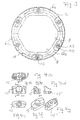
- FIG. 1 shows a first exemplary embodiment of a vehicle wheel 1 according to the invention in perspective view.
- the vehicle wheel 1 which is preferably used for fork lift trucks, earth-moving machinery, heavy-duty vehicles or similar slow-moving vehicles with high axial load, comprises a solid tire 2 that is connected to a rim 5 by an upper shell 3 and an lower shell 4 .
- the bond of upper (radially outer) shell 3 and lower (radially inner) shell 4 is shown in more detail in a perspective view in FIG. 2 .
- the upper shell 3 comprises three segments 6 a , 6 b and 6 c ;
- the lower shell 4 is likewise composed of three segments 7 a , 7 b and 7 c .
- the segments 6 a through 6 c of the upper shell 3 are connected by a positive connection to the segments 7 a through 7 c of the lower shell 4 in that the radially inner contour 8 of the upper shell 3 and the radially outer contour 9 of the lower shell 4 have the shape of a polygon.
- the segments 6 a and 6 b of the upper shell 3 have a toothing 10 that is used for the axial locking of the segments 6 a and 6 b .
- This locking has proven to be practical in particular when upper shell 3 and lower shell 4 are not braced with one another in a crossed-over manner.
- the toothing thereby helps so that the segments cannot drift apart axially, then resulting in a danger that a solid tire 2 vulcanized on the upper shell 3 could become detached from the upper shell 3 ;
- An expansion joint 11 is arranged between the segments 6 a - 6 c of the upper shell 3 , which can be seen particularly clearly between segments 6 c and 6 a ; accordingly an expansion joint 12 is arranged between the segments 7 a - 7 c of the lower shell 4 , which can be seen particularly between segments 7 c and 7 a .
- the expansion joints 11 and 12 serve to balance thermal expansions when the vehicle wheel 1 is heated during operation or during high outside temperatures. Through the embodiment of the expansion joints 11 and 12 of the configuration shown in FIGS. 1 and 2 , it is ensured that lower shell 4 and upper shell 3 hold together under various temperature conditions.
- FIG. 3 shows the upper shell 3 from FIG. 2 from the side. It is possible to discern here in particular the inner contour 8 embodied as a polygon, the expansion joint 11 and bores 13 in which screws for bracing against the lower shell 4 can be inserted. Recesses 14 are respectively sunk around the bores 13 , into which recesses pressure cases 15 are inserted.
- the pressure cases 15 are shown in FIGS. 4 a through 4 g from below, from above, in a perspective view from above and below and in sectional representations in a self-explanatory manner.
- the pressure cases 15 can be composed of metallic materials, in particular of diecast aluminum or zinc die-casting, or of glass fiber reinforced plastic.
- the upper shell 3 and the lower shell 4 are composed respectively of plastic, in particular of polyamide. The pressure cases are used to better distribute the pressure exerted by the screws on the upper shell 3 and the lower shell 4 .
- FIGS. 5 a and 5 b show two segments 6 a and 6 c of the upper shell in a perspective view.
- the toothing 10 and a dirt guard 16 can be discerned in particular there.
- the dirt guard 16 serves a self-cleaning purpose in that dirt that has possibly penetrated into the segment separation joints during thermal expansion can be pressed out again.
- FIG. 5 b shows a stop edge 17 , which will be discussed in detail later.
- FIGS. 6 a and 6 b show segments 7 a and 7 b of the lower shell 4 , which segments have congruent mating surfaces to the segments 6 a and 6 c of the upper shell 3 shown in FIGS. 5 a and 5 b .
- the segment 7 b has a click-stop element 18 that interacts with a click-stop element 19 shaped accordingly of the segment 7 a .
- This renders possible a simple assembly of the segments 7 a , 7 b and 7 c on the rim, in that the individual segments 7 a through 7 c are simply placed on a compression rubber on the rim 5 and engaged with one another.
- FIG. 7 shows a rim 5 on which a segment 7 a of the lower shell 4 and a segment 6 a of the upper shell 3 is placed, whereby in addition a partial section of a solid tire 2 can be seen.
- the segments 6 a - 6 c of the upper shell 3 are provided with click-stop elements 20 , 21 which are used for the simple joining of the segments 6 a - 6 c and in addition the radial and axial locking.
- FIG. 8 shows another exemplary embodiment of a vehicle wheel 1 according to the invention in a radial section.
- the lower shell 4 and the upper shell 3 are braced against one another by a screw 22 , whereby the screw 22 is supported in pressure cases 15 , whereby a nut 23 is supported in a pressure case 15 of the lower shell 4 .
- 24 indicates a metallic belt.
- the stop edge 17 of the upper shell 3 abuts against a corresponding stop edge 25 of the lower shell 4 .
- a radially upper and axially outer surface 26 is embodied such that it is aligned at the same height with a radially upper and axially outer surface 27 of the lower shell 4 .
- This embodiment makes it possible to use a solid tire 2 that is not connected to the upper shell 3 by vulcanization, but is tensioned on the rim by the upper shell 3 and the lower shell 4 as a separate component and is thus supported. This makes it possible to use the upper shell 3 as a separate component without it being necessary to convey the upper shell 3 to another vulcanization when a solid tire 2 is replaced.
- FIG. 9 shows another exemplary embodiment of a vehicle wheel according to the invention in a radial section.
- the vehicle wheel 1 shown in FIG. 9 thereby largely corresponds to the embodiment shown in FIG. 8 , whereby, however, in contrast to the embodiment shown in FIG. 8 , the solid tire 2 is firmly joined to the upper shell 3 , namely by vulcanization.
- radially upper and axially outer areas of the upper shell 3 are provided with a spherical shoulder 28 , through which the radially outer contour of the upper shell 3 as a whole is given the shape of a saddle 29 . This counteracts stress cracks that can occur with high axle loads.
- the belt 24 has a connection 30 to the screw 22 , whereby this connection 30 to the screw 22 is used for dissipating electrostatic discharges, resistance ⁇ 10 6 Ohm, over the rim 5 . Furthermore, if the screw 22 does not have a connection to the rim 5 via the pressure case 15 , furthermore a corresponding connection can be provided from the screw 22 to the rim 5 . If the upper shell 3 and lower shell 4 are made of plastic, such as polyamide, the dissipation of static discharges can also be carried out in that electrically conducting carbon black is mixed into the plastic.
Abstract
Description
- 1 Vehicle wheel
- 2 Solid tire
- 3 Upper shell
- 4 Lower shell
- 5 Rim
- 6 b, 6 c Segments
- 7 b, 7 c Segments
- 8 Radially inner contour
- 9 Radially outer contour
- 10 Toothing
- 11 Expansion joint
- 12 Expansion joint
- 13 Bore
- 14 Recess
- 15 Pressure case
- 16 Dirt guard
- 17 Stop edge
- 18 Click-stop element
- 19 Click-stop element
- 20 Click-stop element
- 21 Click-stop element
- 22 Screw
- 23 Nut
- 24 Belt
- 25 Stop edge
- 26 Surface
- 27 Surface
- 28 Shoulder
- 29 Saddle
- 30 Connection
- 31 Compression rubber
Claims (16)
Applications Claiming Priority (1)
| Application Number | Priority Date | Filing Date | Title |
|---|---|---|---|
| PCT/EP2004/010927 WO2006037353A1 (en) | 2004-09-30 | 2004-09-30 | Vehicle wheel comprising a wheel rim and a rubber tyre |
Publications (2)
| Publication Number | Publication Date |
|---|---|
| US20070240800A1 US20070240800A1 (en) | 2007-10-18 |
| US7726370B2 true US7726370B2 (en) | 2010-06-01 |
Family
ID=34958874
Family Applications (1)
| Application Number | Title | Priority Date | Filing Date |
|---|---|---|---|
| US11/569,143 Expired - Fee Related US7726370B2 (en) | 2004-09-30 | 2004-09-30 | Vehicle wheel comprising a wheel rim and rubber tire |
Country Status (11)
| Country | Link |
|---|---|
| US (1) | US7726370B2 (en) |
| EP (1) | EP1799469B1 (en) |
| JP (1) | JP4499790B2 (en) |
| KR (1) | KR101077004B1 (en) |
| CN (1) | CN100482479C (en) |
| AT (1) | ATE384626T1 (en) |
| BR (1) | BRPI0418859B1 (en) |
| DE (1) | DE502004006091D1 (en) |
| ES (1) | ES2299859T3 (en) |
| MX (1) | MXPA06013822A (en) |
| WO (1) | WO2006037353A1 (en) |
Cited By (8)
| Publication number | Priority date | Publication date | Assignee | Title |
|---|---|---|---|---|
| US20140083585A1 (en) * | 2012-09-24 | 2014-03-27 | Lindsay Corporation | Wheel and tire assembly |
| US9090121B2 (en) | 2012-04-25 | 2015-07-28 | Lindsey Corporation | Wheel and tire assembly |
| US9242510B2 (en) | 2012-09-24 | 2016-01-26 | Lindsay Corporation | Wheel and tire assembly and method of assembly |
| US9266506B2 (en) | 2012-04-25 | 2016-02-23 | Lindsay Corporation | Wheel and tire assembly with adjustable spacer system |
| US9302539B2 (en) | 2012-04-25 | 2016-04-05 | Lindsay Corporation | Wheel and tire assembly |
| US10457100B2 (en) | 2017-07-26 | 2019-10-29 | gowheels, Inc. | Cart wheel assembly with replaceable tire |
| USD917124S1 (en) | 2020-04-13 | 2021-04-20 | gowheels, Inc. | Wheel assembly with replaceable tire |
| USD926416S1 (en) | 2020-01-14 | 2021-07-27 | gowheels, Inc. | Pair of tire segment ends for a seam joint on a replaceable tire |
Families Citing this family (11)
| Publication number | Priority date | Publication date | Assignee | Title |
|---|---|---|---|---|
| US9139046B2 (en) * | 2007-11-13 | 2015-09-22 | Caterpillar, Inc. | Adjustable insert for a tire |
| JP6085903B2 (en) * | 2012-05-29 | 2017-03-01 | 横浜ゴム株式会社 | Non pneumatic tire |
| USD792332S1 (en) | 2015-06-03 | 2017-07-18 | Mtd Products Inc | Non-pneumatic tire |
| US10899169B2 (en) | 2015-01-27 | 2021-01-26 | Mtd Products Inc | Wheel assemblies with non-pneumatic tires |
| US20160214435A1 (en) | 2015-01-27 | 2016-07-28 | Mtd Products Inc | Wheel assemblies with non-pneumatic tires |
| USD784917S1 (en) | 2015-06-03 | 2017-04-25 | Mtd Products Inc | Non-pneumatic tire |
| DE102016212509A1 (en) * | 2016-07-08 | 2018-01-11 | Continental Reifen Deutschland Gmbh | vehicle tires |
| CN107444015A (en) * | 2017-08-10 | 2017-12-08 | 曾小成 | One kind is without gas spring cushion tyre and its manufacture method |
| CN110228331A (en) * | 2019-06-20 | 2019-09-13 | 中国五冶集团有限公司 | A kind of solid tyre wheel and preparation method thereof |
| WO2021137957A1 (en) * | 2019-12-30 | 2021-07-08 | Bridgestone Americas Tire Operations, Llc | Non-pneumatic tire having sidewall covers |
| KR102471309B1 (en) * | 2021-04-16 | 2022-11-28 | 넥센타이어 주식회사 | Airless tire |
Citations (9)
| Publication number | Priority date | Publication date | Assignee | Title |
|---|---|---|---|---|
| DE190743C (en) | ||||
| US575230A (en) * | 1897-01-12 | Tire-tightener | ||
| GB190707250A (en) | 1907-03-26 | 1907-12-05 | Reilloc Tyre Company Ltd | Improvements relating to Sectional Elastic Vehicle-tyres. |
| US1067744A (en) * | 1912-08-21 | 1913-07-15 | William Joseph Lane | Demountable-rim. |
| US1128531A (en) * | 1914-12-04 | 1915-02-16 | Nicholas Schenk | Demountable rim for vehicle-wheels. |
| US1299205A (en) * | 1916-06-03 | 1919-04-01 | Ralph L Morgan | Demountable rim for vehicle-tires. |
| US1340244A (en) * | 1919-03-27 | 1920-05-18 | Arthur T Bradlee | Demountable rim |
| US2113379A (en) * | 1934-08-09 | 1938-04-05 | Wingfoot Corp | Cushion wheel |
| EP1312489A2 (en) | 2001-11-15 | 2003-05-21 | Continental Aktiengesellschaft | Vehicle wheel with rim and solid tyre |
Family Cites Families (2)
| Publication number | Priority date | Publication date | Assignee | Title |
|---|---|---|---|---|
| GB191407250A (en) * | 1914-03-23 | 1915-03-11 | Thomas Gare | Improvements relating to Solid Rubber Tyres for Vehicles. |
| CH591346A5 (en) * | 1975-12-24 | 1977-09-15 | Fischer Ag Georg |
-
2004
- 2004-09-30 CN CNB2004800441085A patent/CN100482479C/en not_active Expired - Fee Related
- 2004-09-30 US US11/569,143 patent/US7726370B2/en not_active Expired - Fee Related
- 2004-09-30 BR BRPI0418859-4A patent/BRPI0418859B1/en not_active IP Right Cessation
- 2004-09-30 DE DE502004006091T patent/DE502004006091D1/en active Active
- 2004-09-30 MX MXPA06013822A patent/MXPA06013822A/en active IP Right Grant
- 2004-09-30 JP JP2007533874A patent/JP4499790B2/en not_active Expired - Fee Related
- 2004-09-30 AT AT04765711T patent/ATE384626T1/en not_active IP Right Cessation
- 2004-09-30 EP EP04765711A patent/EP1799469B1/en not_active Not-in-force
- 2004-09-30 KR KR1020077000110A patent/KR101077004B1/en not_active IP Right Cessation
- 2004-09-30 ES ES04765711T patent/ES2299859T3/en active Active
- 2004-09-30 WO PCT/EP2004/010927 patent/WO2006037353A1/en active IP Right Grant
Patent Citations (9)
| Publication number | Priority date | Publication date | Assignee | Title |
|---|---|---|---|---|
| DE190743C (en) | ||||
| US575230A (en) * | 1897-01-12 | Tire-tightener | ||
| GB190707250A (en) | 1907-03-26 | 1907-12-05 | Reilloc Tyre Company Ltd | Improvements relating to Sectional Elastic Vehicle-tyres. |
| US1067744A (en) * | 1912-08-21 | 1913-07-15 | William Joseph Lane | Demountable-rim. |
| US1128531A (en) * | 1914-12-04 | 1915-02-16 | Nicholas Schenk | Demountable rim for vehicle-wheels. |
| US1299205A (en) * | 1916-06-03 | 1919-04-01 | Ralph L Morgan | Demountable rim for vehicle-tires. |
| US1340244A (en) * | 1919-03-27 | 1920-05-18 | Arthur T Bradlee | Demountable rim |
| US2113379A (en) * | 1934-08-09 | 1938-04-05 | Wingfoot Corp | Cushion wheel |
| EP1312489A2 (en) | 2001-11-15 | 2003-05-21 | Continental Aktiengesellschaft | Vehicle wheel with rim and solid tyre |
Cited By (11)
| Publication number | Priority date | Publication date | Assignee | Title |
|---|---|---|---|---|
| US9090121B2 (en) | 2012-04-25 | 2015-07-28 | Lindsey Corporation | Wheel and tire assembly |
| US9266506B2 (en) | 2012-04-25 | 2016-02-23 | Lindsay Corporation | Wheel and tire assembly with adjustable spacer system |
| US9302539B2 (en) | 2012-04-25 | 2016-04-05 | Lindsay Corporation | Wheel and tire assembly |
| US9821601B2 (en) | 2012-04-25 | 2017-11-21 | Lindsay Corporation | Wheel and tire assembly |
| US20140083585A1 (en) * | 2012-09-24 | 2014-03-27 | Lindsay Corporation | Wheel and tire assembly |
| US9186934B2 (en) * | 2012-09-24 | 2015-11-17 | Lindsay Corporation | Wheel and tire assembly |
| US9242510B2 (en) | 2012-09-24 | 2016-01-26 | Lindsay Corporation | Wheel and tire assembly and method of assembly |
| US10457100B2 (en) | 2017-07-26 | 2019-10-29 | gowheels, Inc. | Cart wheel assembly with replaceable tire |
| US10730349B2 (en) | 2017-07-26 | 2020-08-04 | gowheels, Inc. | Replaceable tire for use in a wheel assembly for carts |
| USD926416S1 (en) | 2020-01-14 | 2021-07-27 | gowheels, Inc. | Pair of tire segment ends for a seam joint on a replaceable tire |
| USD917124S1 (en) | 2020-04-13 | 2021-04-20 | gowheels, Inc. | Wheel assembly with replaceable tire |
Also Published As
| Publication number | Publication date |
|---|---|
| ES2299859T3 (en) | 2008-06-01 |
| US20070240800A1 (en) | 2007-10-18 |
| BRPI0418859A (en) | 2007-11-20 |
| JP2008514488A (en) | 2008-05-08 |
| BRPI0418859B1 (en) | 2018-03-06 |
| EP1799469B1 (en) | 2008-01-23 |
| KR101077004B1 (en) | 2011-10-26 |
| ATE384626T1 (en) | 2008-02-15 |
| EP1799469A1 (en) | 2007-06-27 |
| DE502004006091D1 (en) | 2008-03-13 |
| WO2006037353A1 (en) | 2006-04-13 |
| MXPA06013822A (en) | 2007-02-02 |
| KR20070083445A (en) | 2007-08-24 |
| CN100482479C (en) | 2009-04-29 |
| CN101027194A (en) | 2007-08-29 |
| JP4499790B2 (en) | 2010-07-07 |
Similar Documents
| Publication | Publication Date | Title |
|---|---|---|
| US7726370B2 (en) | Vehicle wheel comprising a wheel rim and rubber tire | |
| EP3212432B1 (en) | Wheel for a vehicle | |
| EP0529492B1 (en) | A plastic wheel | |
| US10704637B2 (en) | Bar pin bushing for vehicle suspension | |
| US20090129854A1 (en) | Assembly comprising a carrier part and a ball joint housing | |
| US20090065989A1 (en) | Air spring modular piston | |
| US11440371B2 (en) | Bearing for stabilizer bar provided with a backing plate | |
| US6902345B2 (en) | Ball joint | |
| US20030155698A1 (en) | Resilient joint for vehicle suspension | |
| US11772423B2 (en) | Reusable rim for non-pneumatic tires | |
| JP2007523794A (en) | Seal ring for automobile wheel | |
| US11385117B2 (en) | Tire pressure monitoring module with thru-valve construction | |
| US11020921B2 (en) | Connecting member for an air maintenance tire and method of forming the same | |
| US20180099535A1 (en) | Air maintenance tire system component protector | |
| CN114683761B (en) | Rim | |
| CN217294126U (en) | Improved rim structure | |
| CN111219413B (en) | Suspension bearing collar with coupling portion for a motor vehicle | |
| WO2009060270A1 (en) | Visual indication device of the coupling condition between two mechanical members | |
| KR101843295B1 (en) | A pneumatic tire | |
| CA1172274A (en) | Spigot assembly for attaching the knuckle of a vehicle suspension member to a relatively movable part of a vehicle | |
| NL1010710C1 (en) | Hidden type quick release wheel hub assembly. | |
| US20060086446A1 (en) | Device intended to lock the beads of a tire cover against the flanges of a rim | |
| CN112537167A (en) | Wheel and have its vehicle | |
| JPH1159337A (en) | Vehicular part and structure for installing the same | |
| JP2003205703A (en) | Tire device, tire constituting method, and split tire element |
Legal Events
| Date | Code | Title | Description |
|---|---|---|---|
| AS | Assignment |
Owner name: CONTINENTAL AKTIENGESELLSCHAFT, GERMANY Free format text: ASSIGNMENT OF ASSIGNORS INTEREST;ASSIGNOR:SAUERWALD, JUERGEN H.;REEL/FRAME:018522/0673 Effective date: 20061102 Owner name: CONTINENTAL AKTIENGESELLSCHAFT,GERMANY Free format text: ASSIGNMENT OF ASSIGNORS INTEREST;ASSIGNOR:SAUERWALD, JUERGEN H.;REEL/FRAME:018522/0673 Effective date: 20061102 |
|
| AS | Assignment |
Owner name: CONTINENTAL AKTIENGESELLSCHAFT,GERMANY Free format text: CORRECTIVE ASSIGNMENT TO CORRECT THE ASSIGNOR'S INFORMATION PREVIOUSLY RECORDED ON REEL 018522 FRAME 0673. ASSIGNOR(S) HEREBY CONFIRMS THE ASSIGNOR'S INFORMATION SHOULD INCLUDE THE NAME OF THE SECOND ASSIGNOR KLAUS SCHOLZ;ASSIGNORS:SAUERWALD, JUERGEN H;SCHOLZ, KLAUS;REEL/FRAME:024109/0938 Effective date: 20061102 |
|
| FEPP | Fee payment procedure |
Free format text: PAYOR NUMBER ASSIGNED (ORIGINAL EVENT CODE: ASPN); ENTITY STATUS OF PATENT OWNER: LARGE ENTITY |
|
| FPAY | Fee payment |
Year of fee payment: 4 |
|
| AS | Assignment |
Owner name: CONTINENTAL REIFEN DEUTSCHLAND GMBH, GERMANY Free format text: CHANGE OF NAME;ASSIGNOR:CONTINENTAL AKTIENGESELLSCHAFT;REEL/FRAME:032548/0264 Effective date: 20101001 |
|
| AS | Assignment |
Owner name: CONTINENTAL REIFEN DEUTSCHLAND GMBH, GERMANY Free format text: CORRECTIVE ASSIGNMENT TO CORRECT THE NATURE OF CONVEYANCE PREVIOUSLY RECORDED ON REEL 032548 FRAME 0264. ASSIGNOR(S) HEREBY CONFIRMS THE NATURE OF CONVEYANCESHOULD BE "ASSIGNMENT";ASSIGNOR:CONTINENTAL AKTIENGESELLSCHAFT;REEL/FRAME:032608/0890 Effective date: 20101001 |
|
| FEPP | Fee payment procedure |
Free format text: MAINTENANCE FEE REMINDER MAILED (ORIGINAL EVENT CODE: REM.) |
|
| LAPS | Lapse for failure to pay maintenance fees |
Free format text: PATENT EXPIRED FOR FAILURE TO PAY MAINTENANCE FEES (ORIGINAL EVENT CODE: EXP.) |
|
| STCH | Information on status: patent discontinuation |
Free format text: PATENT EXPIRED DUE TO NONPAYMENT OF MAINTENANCE FEES UNDER 37 CFR 1.362 |
|
| FP | Lapsed due to failure to pay maintenance fee |
Effective date: 20180601 |