EP1429901B1 - Vorrichtung und verfahren zur korrektur der krümmung in einem wabenextrudat - Google Patents
Vorrichtung und verfahren zur korrektur der krümmung in einem wabenextrudat Download PDFInfo
- Publication number
- EP1429901B1 EP1429901B1 EP02748171A EP02748171A EP1429901B1 EP 1429901 B1 EP1429901 B1 EP 1429901B1 EP 02748171 A EP02748171 A EP 02748171A EP 02748171 A EP02748171 A EP 02748171A EP 1429901 B1 EP1429901 B1 EP 1429901B1
- Authority
- EP
- European Patent Office
- Prior art keywords
- die
- aperture
- extrusion
- slide plate
- bow
- Prior art date
- Legal status (The legal status is an assumption and is not a legal conclusion. Google has not performed a legal analysis and makes no representation as to the accuracy of the status listed.)
- Expired - Lifetime
Links
- 238000000034 method Methods 0.000 title claims abstract description 8
- 238000001125 extrusion Methods 0.000 claims abstract description 36
- 238000012937 correction Methods 0.000 claims abstract description 15
- 239000000463 material Substances 0.000 claims abstract description 15
- 230000009467 reduction Effects 0.000 abstract description 6
- 238000011144 upstream manufacturing Methods 0.000 abstract description 3
- 238000013461 design Methods 0.000 description 5
- 238000004519 manufacturing process Methods 0.000 description 5
- 239000000758 substrate Substances 0.000 description 4
- 238000013459 approach Methods 0.000 description 2
- 239000000919 ceramic Substances 0.000 description 2
- 238000005520 cutting process Methods 0.000 description 2
- 238000010348 incorporation Methods 0.000 description 2
- 238000003754 machining Methods 0.000 description 2
- 238000012423 maintenance Methods 0.000 description 2
- 238000009924 canning Methods 0.000 description 1
- 239000003054 catalyst Substances 0.000 description 1
- 239000011248 coating agent Substances 0.000 description 1
- 238000000576 coating method Methods 0.000 description 1
- 230000003247 decreasing effect Effects 0.000 description 1
- 230000007547 defect Effects 0.000 description 1
- 230000000694 effects Effects 0.000 description 1
- 239000003792 electrolyte Substances 0.000 description 1
- 238000010304 firing Methods 0.000 description 1
- 239000002184 metal Substances 0.000 description 1
- 238000007747 plating Methods 0.000 description 1
- 239000000843 powder Substances 0.000 description 1
- 230000000750 progressive effect Effects 0.000 description 1
- 239000000126 substance Substances 0.000 description 1
Images



Classifications
-
- B—PERFORMING OPERATIONS; TRANSPORTING
- B28—WORKING CEMENT, CLAY, OR STONE
- B28B—SHAPING CLAY OR OTHER CERAMIC COMPOSITIONS; SHAPING SLAG; SHAPING MIXTURES CONTAINING CEMENTITIOUS MATERIAL, e.g. PLASTER
- B28B3/00—Producing shaped articles from the material by using presses; Presses specially adapted therefor
- B28B3/20—Producing shaped articles from the material by using presses; Presses specially adapted therefor wherein the material is extruded
- B28B3/26—Extrusion dies
- B28B3/269—For multi-channeled structures, e.g. honeycomb structures
-
- B—PERFORMING OPERATIONS; TRANSPORTING
- B28—WORKING CEMENT, CLAY, OR STONE
- B28B—SHAPING CLAY OR OTHER CERAMIC COMPOSITIONS; SHAPING SLAG; SHAPING MIXTURES CONTAINING CEMENTITIOUS MATERIAL, e.g. PLASTER
- B28B3/00—Producing shaped articles from the material by using presses; Presses specially adapted therefor
- B28B3/20—Producing shaped articles from the material by using presses; Presses specially adapted therefor wherein the material is extruded
-
- B—PERFORMING OPERATIONS; TRANSPORTING
- B28—WORKING CEMENT, CLAY, OR STONE
- B28B—SHAPING CLAY OR OTHER CERAMIC COMPOSITIONS; SHAPING SLAG; SHAPING MIXTURES CONTAINING CEMENTITIOUS MATERIAL, e.g. PLASTER
- B28B3/00—Producing shaped articles from the material by using presses; Presses specially adapted therefor
- B28B3/20—Producing shaped articles from the material by using presses; Presses specially adapted therefor wherein the material is extruded
- B28B3/26—Extrusion dies
- B28B3/2672—Means for adjusting the flow inside the die, e.g. using choke means
-
- B—PERFORMING OPERATIONS; TRANSPORTING
- B29—WORKING OF PLASTICS; WORKING OF SUBSTANCES IN A PLASTIC STATE IN GENERAL
- B29C—SHAPING OR JOINING OF PLASTICS; SHAPING OF MATERIAL IN A PLASTIC STATE, NOT OTHERWISE PROVIDED FOR; AFTER-TREATMENT OF THE SHAPED PRODUCTS, e.g. REPAIRING
- B29C48/00—Extrusion moulding, i.e. expressing the moulding material through a die or nozzle which imparts the desired form; Apparatus therefor
- B29C48/03—Extrusion moulding, i.e. expressing the moulding material through a die or nozzle which imparts the desired form; Apparatus therefor characterised by the shape of the extruded material at extrusion
- B29C48/09—Articles with cross-sections having partially or fully enclosed cavities, e.g. pipes or channels
- B29C48/11—Articles with cross-sections having partially or fully enclosed cavities, e.g. pipes or channels comprising two or more partially or fully enclosed cavities, e.g. honeycomb-shaped
-
- B—PERFORMING OPERATIONS; TRANSPORTING
- B29—WORKING OF PLASTICS; WORKING OF SUBSTANCES IN A PLASTIC STATE IN GENERAL
- B29C—SHAPING OR JOINING OF PLASTICS; SHAPING OF MATERIAL IN A PLASTIC STATE, NOT OTHERWISE PROVIDED FOR; AFTER-TREATMENT OF THE SHAPED PRODUCTS, e.g. REPAIRING
- B29C48/00—Extrusion moulding, i.e. expressing the moulding material through a die or nozzle which imparts the desired form; Apparatus therefor
- B29C48/03—Extrusion moulding, i.e. expressing the moulding material through a die or nozzle which imparts the desired form; Apparatus therefor characterised by the shape of the extruded material at extrusion
- B29C48/131—Curved articles
-
- B—PERFORMING OPERATIONS; TRANSPORTING
- B29—WORKING OF PLASTICS; WORKING OF SUBSTANCES IN A PLASTIC STATE IN GENERAL
- B29C—SHAPING OR JOINING OF PLASTICS; SHAPING OF MATERIAL IN A PLASTIC STATE, NOT OTHERWISE PROVIDED FOR; AFTER-TREATMENT OF THE SHAPED PRODUCTS, e.g. REPAIRING
- B29C48/00—Extrusion moulding, i.e. expressing the moulding material through a die or nozzle which imparts the desired form; Apparatus therefor
- B29C48/25—Component parts, details or accessories; Auxiliary operations
- B29C48/255—Flow control means, e.g. valves
- B29C48/2556—Flow control means, e.g. valves provided in or in the proximity of dies
-
- B—PERFORMING OPERATIONS; TRANSPORTING
- B29—WORKING OF PLASTICS; WORKING OF SUBSTANCES IN A PLASTIC STATE IN GENERAL
- B29L—INDEXING SCHEME ASSOCIATED WITH SUBCLASS B29C, RELATING TO PARTICULAR ARTICLES
- B29L2031/00—Other particular articles
- B29L2031/60—Multitubular or multicompartmented articles, e.g. honeycomb
Definitions
- the present invention relates to an apparatus offering extruded honeycomb structures with improved dimensional accuracy, and more particularly to an apparatus for overcoming the problem of bow in an extrudate.
- Ceramic honeycomb substrates for automotive applications are generally produced by cutting and firing individual pieces from a stream of honeycomb extrudate, or by cutting the pieces from a dried green or fired ceramic "log" of extrudate which may be of meter or greater length.
- US 6,039,908 discloses an apparatus and a method for extruding a honeycomb, providing reductions in curvature or bowing of the extruded honeycomb structure with a bow deflector. To meet customer requirements for the subsequent catalyst coating and "canning" of these substrates in suitable metal enclosures, it is important that he logs and pieces cut from the logs have sides which are absolutely straight and parallel.
- a bow deflector which comprises two aperture plates which co-act to alter the flow of the extrudable material to the die.
- Each of the aperture plates are tapered, varying in thickness from one edge to the other, and each comprises apertures through its thickness aligned in a direction parallel to the extrusion axis.
- Each aperture plate is independently rotatable about the extrusion axis with respect to both the die and the other aperture plate. Rotating the tapered plates relative to each changes the amount of bow correction available, by increasing or decreasing the differential in total aperture length between the longest and shortest aperture sets across the bow deflector.
- the present invention overcomes the problem of bow in a honeycomb extrudate through the use of a bow correction device of improved design. That design permits bow correction to be made over a relatively wide range of bowing conditions, and without any need to change bow deflectors.
- the invention includes improved apparatus for the extrusion of honeycomb structures which comprises, in combination, a honeycomb die of any suitable design (which need not be bow-corrected) and a bow correction device having a singular aperture which acts to alter the flow of extrudable material to the die in an exact and controllable manner.
- the honeycomb extrusion die employed in the apparatus of the invention has an inlet face comprising a plurality of feed holes and an outlet face comprising a discharge opening.
- the discharge opening is configured in the conventional manner to produce an extrudate of honeycomb configuration from a flow stream of plastic material flowing downstream through the die along an extrusion axis parallel with the direction of extrusion.
- the bow deflector which is positioned in the flow stream immediately upstream of and adjacent the inlet face of the die, comprises a base having an aperture through its thickness aligned in a direction parallel to the extrusion axis, and a slide plate movably mounted to the base. The slide plate moves relative to the base plate controlling the diameter of the aperture.
- Controlling the diameter of the aperture will change the amount of bow correction available, while changing the position of the slide plate relative to die the extrusion apparatus, will change the direction of the bow, such that the flow velocity gradient across the face of the feed stream exiting the deflector device and entering the extrusion die may be controlled as to both magnitude and direction.
- Another aspect of the invention comprises an improved method for extruding a honeycomb structure from a plasticized powder batch material.
- a feed stream of the plasticized batch material is first directed along an extrusion path through an aperture in a device disposed across the feed stream.
- the deflector device has a flow resistance which varies across its length, thereby impressing a flow velocity or pressure drop gradient across the face of the feed stream traversing the deflector device.
- the result of this superimposed pressure drop is that a flow velocity gradient is developed across the face of the feed stream by passage through the deflector device.
- the feed stream with the flow velocity gradient is directed into and through the honeycomb extrusion die.
- Figure 1 is a schematic top view illustration of the components of a deflector device provided in accordance with the present invention
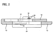
- Figure 2 is a schematic side view of section A-A through the top view of Figure 1 ;
- Figures 3a-3b are schematic views of extrusion apparatus without extrudate bow correction and with bow correction as provided by incorporation of a deflector device as illustrated in Figures 1 and 2 .
- deflector device 10 comprises a base 12 and a slide plate 14 movably mounted to base 12.
- base 12 is outfitted with a pair of elongated slots 16 which are mirrored by slots 18 on slide plate 14.
- Bolts 20 attach slide plate 14 to base 12, and pins 21 guide its movement.
- the plasticized batch or extrudate flows through aperture 24 in base 12.
- Aperture 24 has a varying or adjustable diameter controllable by slide plate 14 which moves relative to base 12 in the direction of the arrow as shown in Figure 1 .
- the degree of bow correction flexibility in the design shown is dictated by aperture 24.
- the deflector device offers a flow, resistance which varies across its length, which is impressed across the face of the feed stream correcting the degree of bow.
- Slide plate 14 can be mounted at various set points 22 in accordance with the measured bow in the extrudate. Typically the degree of bow in an extrudate is measured from the center to ends. In Figure 1 , slide plate 14 is aligned with set points 22e, which provides an intermediate amount of bow correction. Setpoint 22a provides the minimum-correction position. Conversely, setpoint 22h provides the maximum-correction position.
- Figures 3a and 3b is a schematic side elevational view of extrusion apparatus incorporating a deflector device of the presently preferred type. These views are intended to illustrate the manner in which the flow velocity of a stream of plasticized batch material can be adjusted by incorporating a deflector device of the present invention.
- FIG 3a a left bow is shown in an extrusion apparatus without a bow correction device.
- the plasticized batch material 100 flows into die feed holes 30a of die 30 in the direction of arrows 40 and is extruded from die discharge slots 30b.
- the resulting extrudate 110 is bowed to the left because batch 100 is flowing at a faster rate near die end 32, the right hand side of die 30, than die end 34, the left hand side of die 30.
- the bowing problem is corrected by incorporation of deflector device 10 upstream of extrusion die 30, with slide plate 14 positioned adjacent die end 32, to slow down the flow rate thereat by forcing batch 100 to flow around slide plate 14 and to follow a tortuous path as indicated by arrow 42.
- slide plate 14 It is important to position slide plate 14 adjacent the die end at which the extrudate has a faster flowing rate. For example if a right bow occurred such that the extrudate flowed faster adjacent die end 32, then slide plate 14 would be positioned adjacent die end 34 of die 30. Therefore deflector device 10 is positioned in extrusion apparatus with slide plate 14 adjacent the die end opposite direction of bow in the honeycomb extrudate, such that the direction of bow in the present invention shown is dictated by the position of the slide plate, as discussed previously.
- the deflector device is shown to be adjustable only prior to positioning in extrusion apparatus, it is contemplated that in another embodiment the device of the present invention would also be able of being adjusted for varying degrees of bow correction during the manufacturing process without interruption to production.
- extrusion apparatus includes: (1) reduction of swollen webs in extruded honeycomb substrates; (2) compatible with extrusion of thin and ultra-thin honeycomb substrates; (3) reduction in preferential flow in conventional dies; (4) reduction in maintenance costs; and, (5) reduction in extrusion pressure.
Landscapes
- Engineering & Computer Science (AREA)
- Mechanical Engineering (AREA)
- Manufacturing & Machinery (AREA)
- Chemical & Material Sciences (AREA)
- Ceramic Engineering (AREA)
- Press-Shaping Or Shaping Using Conveyers (AREA)
- Extrusion Moulding Of Plastics Or The Like (AREA)
Claims (5)
- Vorrichtung für die Extrusion einer Wabenstruktur, in Kombination aufweisend:a) eine Wabenextrusionsdüse (30), welche eine Einlassfläche, welche Zuführlöcher (30a) aufweist, und eine Auslassfläche aufweist, welche eine Austrittsöffnung (30b) aufweist, wobei die Austrittsöffnung (30b) ausgebildet ist, um ein Wabenextrudat aus einem Strom aus Plastikmaterial (100, 110) zu bilden, welcher auf einer Extrusionsachse (40) durch die Düse (30) fließt, undb) eine Bogendeflektoreinrichtung (10), welche neben der Einlassfläche der Extrusionsdüse positioniert ist, wobei die Deflektoreinrichtung (10) aufweist:i) eine Basisplatte (12); undii) eine Gleitplatte (14), welche beweglich auf der Basisplatte (12) gelagert ist,
dadurch gekennzeichnet,
dass die Basisplatte (12) eine einzelne Öffnung (24) aufweist, welche in eine Richtung parallel zu der Extrusionsachse (40) ausgerichtet ist, durch welche das Plastikmaterial zu der Düse (30) befördert wird, wobei der Durchmesser der Öffnung (24) durch die Gleitplatte (14) einstellbar ist, welche bezüglich der Basisplatte (12) beweglich ist. - Vorrichtung nach Anspruch 1, wobei die Basis (12) ferner eine Vielzahl von Einstellwerten (22) aufweist, welche Positionen entsprechen, an welchen die Gleitplatte (14) abhängig von dem Grad der benötigten Bogenkorrektur bewegt werden kann.
- Vorrichtung nach Anspruch 2, wobei die Deflektoreinrichtung (10) mit der Gleitplatte (14) in einer entgegengesetzten Richtung des Bogens in dem Wabenextrudat positioniert ist, welches aus der Düse (30) fließt, um die Richtung des Bogens zu steuern.
- Verfahren zum Bilden einer Wabenstruktur aus einem extrudierbaren Material, wobei das Verfahren aufweist:a) Bereitstellen einer plastifizierten Charge eines Extrudats (100);b) Leiten eines Zuführstromes des Extrudats (100) entlang eines Extrusionspfades durch eine Deflektoreinrichtung (10), welche eine Basisplatte (12) und eine Gleitplatte (14), welche beweglich auf der Basisplatte (12) gelagert ist, aufweist, wobei die Deflektoreinrichtung (10) einen einstellbaren veränderlichen Fließwiderstand quer zu seiner Länge aufweist, um eine Fließgeschwindigkeit oder einen Druckabfallgradienten quer zum Zuführstrom zur Verfügung zu stellen;c) Leiten des Zuführstromes mit der überlagerten Fließgeschwindigkeit oder dem Druckverlustgradienten durch eine Wabenextrusionsdüse (30),
dadurch gekennzeichnet,
dass die Basisplatte (12) eine einzelne Öffnung (24) aufweist, welche in eine Richtung parallel zu der Extrusionsachse (40) ausgerichtet ist, durch welche das Plastikmaterial zu der Düse (30) befördert wird, wobei der Durchmesser der Öffnung (24) durch die Gleitplatte (14) einstellbar ist, welche bezüglich der Basisplatte (12) beweglich ist. - Verfahren nach Anspruch 4, wobei die Öffnung (24) einen veränderlichen Durchmesser aufweist, und wobei der veränderliche Fließwiderstand quer zur Deflektoreinrichtung (10) sich durch eine Veränderung in der Öffnung (24) ergibt.
Applications Claiming Priority (3)
| Application Number | Priority Date | Filing Date | Title |
|---|---|---|---|
| US967110 | 1978-12-06 | ||
| US09/967,110 US6663378B2 (en) | 2001-09-27 | 2001-09-27 | Apparatus for correcting bow in a honeycomb extrudate |
| PCT/US2002/022537 WO2003026863A1 (en) | 2001-09-27 | 2002-07-15 | Apparatus and method of correcting bow in a honeycomb extrudate |
Publications (3)
| Publication Number | Publication Date |
|---|---|
| EP1429901A1 EP1429901A1 (de) | 2004-06-23 |
| EP1429901A4 EP1429901A4 (de) | 2009-08-26 |
| EP1429901B1 true EP1429901B1 (de) | 2011-05-18 |
Family
ID=25512313
Family Applications (1)
| Application Number | Title | Priority Date | Filing Date |
|---|---|---|---|
| EP02748171A Expired - Lifetime EP1429901B1 (de) | 2001-09-27 | 2002-07-15 | Vorrichtung und verfahren zur korrektur der krümmung in einem wabenextrudat |
Country Status (7)
| Country | Link |
|---|---|
| US (1) | US6663378B2 (de) |
| EP (1) | EP1429901B1 (de) |
| JP (1) | JP4202917B2 (de) |
| CN (1) | CN1274482C (de) |
| TW (1) | TW550162B (de) |
| WO (1) | WO2003026863A1 (de) |
| ZA (1) | ZA200402049B (de) |
Families Citing this family (17)
| Publication number | Priority date | Publication date | Assignee | Title |
|---|---|---|---|---|
| US20040164464A1 (en) * | 2003-02-21 | 2004-08-26 | Lubberts Robert B. | Device and method of correcting extrudate bow |
| US6991448B2 (en) * | 2003-04-01 | 2006-01-31 | Corning Incorporated | Apparatus for extruding honeycomb bodies |
| JP2008522873A (ja) * | 2004-12-09 | 2008-07-03 | コーニング インコーポレイテッド | ハニカム押出ダイの製造 |
| GB2470937B (en) | 2009-06-10 | 2014-09-24 | Cadbury Uk Ltd | Extrusion die head |
| TWI449617B (zh) * | 2010-08-24 | 2014-08-21 | Briview Corp | 模具結構及模具系統 |
| KR20130140667A (ko) * | 2010-09-17 | 2013-12-24 | 스미또모 가가꾸 가부시끼가이샤 | 압출 성형 장치 및 이것을 사용한 성형체의 제조 방법 |
| JP6196219B2 (ja) * | 2011-08-26 | 2017-09-13 | ダウ グローバル テクノロジーズ エルエルシー | セラミック体を作製する改良された方法 |
| US10632662B2 (en) | 2013-10-23 | 2020-04-28 | Corning Incorporated | Device and method of correcting extrudate bow |
| US9393716B2 (en) * | 2013-10-23 | 2016-07-19 | Corning Incorporated | Device and method of correcting extrudate bow |
| WO2016085781A1 (en) | 2014-11-25 | 2016-06-02 | Corning Incorporated | Methods of in-line extrudate inspection and feedback control for honeycomb body manufacture |
| JP2019503892A (ja) | 2015-11-30 | 2019-02-14 | コーニング インコーポレイテッド | ハニカム体のための担体及び方法 |
| US11345059B2 (en) | 2016-06-08 | 2022-05-31 | Corning Incorporated | Methods of laser machining wet cellular ceramic extrudate for honeycomb body manufacture |
| JP6665840B2 (ja) * | 2017-08-21 | 2020-03-13 | 横浜ゴム株式会社 | ゴム押出装置およびゴム押出物の製造方法 |
| WO2019070797A1 (en) | 2017-10-05 | 2019-04-11 | Corning Incorporated | SCREW ELEMENTS FOR EXTRUSION APPARATUS AND METHODS OF MANUFACTURING HONEYCOMB BODY |
| WO2019070796A1 (en) | 2017-10-05 | 2019-04-11 | Corning Incorporated | MIXING ELEMENTS FOR EXTRUSION APPARATUS AND METHODS OF MANUFACTURING HONEYCOMB BODY |
| US12036698B2 (en) | 2019-03-18 | 2024-07-16 | Corning Incorporated | System and method for controlling flow distribution of extrudate source material for fabricating a honeycomb extrudate |
| US11115866B2 (en) | 2019-07-31 | 2021-09-07 | Corning Research & Development Corporation | Coordination of shared spectrum distribution to remote units in distributed radio communications systems |
Family Cites Families (7)
| Publication number | Priority date | Publication date | Assignee | Title |
|---|---|---|---|---|
| US4364888A (en) * | 1981-05-04 | 1982-12-21 | Corning Glass Works | Method and apparatus for extruding a honeycomb structure |
| US4468365A (en) | 1982-08-19 | 1984-08-28 | Corning Glass Works | Extrusion dies for thin wall substrates |
| JPH0541847Y2 (de) | 1987-01-13 | 1993-10-22 | ||
| US4915612A (en) | 1989-01-26 | 1990-04-10 | Corning Incorporated | Extrusion die assembly for forming honeycomb structures having thickened outer skin |
| US5219509A (en) * | 1990-11-30 | 1993-06-15 | Corning Incorporated | Method for forming a uniform skin on a cellular substrate |
| JPH085111B2 (ja) | 1992-11-26 | 1996-01-24 | 日本碍子株式会社 | ハニカム構造体の製造装置 |
| US6039908A (en) | 1996-12-04 | 2000-03-21 | Corning Incorporated | Method for honeycomb extrusion using a corrected flow gradient |
-
2001
- 2001-09-27 US US09/967,110 patent/US6663378B2/en not_active Expired - Fee Related
-
2002
- 2002-07-15 WO PCT/US2002/022537 patent/WO2003026863A1/en not_active Ceased
- 2002-07-15 CN CNB028188640A patent/CN1274482C/zh not_active Expired - Lifetime
- 2002-07-15 EP EP02748171A patent/EP1429901B1/de not_active Expired - Lifetime
- 2002-07-15 JP JP2003530481A patent/JP4202917B2/ja not_active Expired - Fee Related
- 2002-09-27 TW TW091122592A patent/TW550162B/zh not_active IP Right Cessation
-
2004
- 2004-03-15 ZA ZA200402049A patent/ZA200402049B/en unknown
Also Published As
| Publication number | Publication date |
|---|---|
| US20030057592A1 (en) | 2003-03-27 |
| WO2003026863A1 (en) | 2003-04-03 |
| ZA200402049B (en) | 2005-05-27 |
| EP1429901A1 (de) | 2004-06-23 |
| CN1558820A (zh) | 2004-12-29 |
| EP1429901A4 (de) | 2009-08-26 |
| CN1274482C (zh) | 2006-09-13 |
| JP4202917B2 (ja) | 2008-12-24 |
| JP2005503280A (ja) | 2005-02-03 |
| TW550162B (en) | 2003-09-01 |
| US6663378B2 (en) | 2003-12-16 |
Similar Documents
| Publication | Publication Date | Title |
|---|---|---|
| US6663378B2 (en) | Apparatus for correcting bow in a honeycomb extrudate | |
| US6039908A (en) | Method for honeycomb extrusion using a corrected flow gradient | |
| JP2005503280A5 (de) | ||
| US20040164464A1 (en) | Device and method of correcting extrudate bow | |
| US9393716B2 (en) | Device and method of correcting extrudate bow | |
| CN105904697B (zh) | 用于调整挤压模具上的平坦部通道长度的系统和方法 | |
| WO2013013033A1 (en) | Sculpted extrusion die and method of adjusting the thickness of an extruded sheet | |
| EP0484841B1 (de) | Extrusionsdüse zur Herstellung flacher Bahnen aus thermoplastischem Kunststoff | |
| DE4400069C1 (de) | Einstellbare Drossel mit flachem Kanalquerschnitt | |
| CN87100178A (zh) | 制造多层板的布料器 | |
| CN105313292B (zh) | 具有定幅系统的多歧管挤出模具及其使用方法 | |
| US6991448B2 (en) | Apparatus for extruding honeycomb bodies | |
| US5499913A (en) | Device for producing honeycomb structural bodies | |
| US20170361516A1 (en) | Device and method of correcting extrudate bow | |
| JP2004081989A (ja) | 塗布装置、及び塗布方法 | |
| JPH0249898B2 (de) | ||
| JP4347301B2 (ja) | グリーンシートの製造方法および製造装置 | |
| SU1316843A2 (ru) | Многоручьева экструзионна головка дл переработки пластмасс | |
| UA12383U (en) | Flat-slotted extrusion head | |
| HK1079481A1 (zh) | 分配流动物质的模具和方法 | |
| HK1079481B (en) | Die and method for dispensing flowable material | |
| DE3049522A1 (de) | Extrusionswerkzeug mit seitlichem extruderanschluss und vorkehrung zum ausgleich umlenkungsbedingter stroemungsfehler im kunststoff-massestrom | |
| JPH04275126A (ja) | 押出成形用金型 |
Legal Events
| Date | Code | Title | Description |
|---|---|---|---|
| PUAI | Public reference made under article 153(3) epc to a published international application that has entered the european phase |
Free format text: ORIGINAL CODE: 0009012 |
|
| 17P | Request for examination filed |
Effective date: 20040310 |
|
| AK | Designated contracting states |
Kind code of ref document: A1 Designated state(s): AT BE BG CH CY CZ DE DK EE ES FI FR GB GR IE IT LI LU MC NL PT SE SK TR |
|
| AX | Request for extension of the european patent |
Extension state: AL LT LV MK RO SI |
|
| REG | Reference to a national code |
Ref country code: DE Ref legal event code: 8566 |
|
| A4 | Supplementary search report drawn up and despatched |
Effective date: 20090723 |
|
| RIC1 | Information provided on ipc code assigned before grant |
Ipc: B29C 31/00 20060101ALN20090717BHEP Ipc: B29C 47/20 20060101ALI20090717BHEP Ipc: B28B 3/20 20060101AFI20090717BHEP |
|
| 17Q | First examination report despatched |
Effective date: 20091016 |
|
| GRAP | Despatch of communication of intention to grant a patent |
Free format text: ORIGINAL CODE: EPIDOSNIGR1 |
|
| GRAS | Grant fee paid |
Free format text: ORIGINAL CODE: EPIDOSNIGR3 |
|
| GRAA | (expected) grant |
Free format text: ORIGINAL CODE: 0009210 |
|
| AK | Designated contracting states |
Kind code of ref document: B1 Designated state(s): BE |
|
| PGFP | Annual fee paid to national office [announced via postgrant information from national office to epo] |
Ref country code: BE Payment date: 20110728 Year of fee payment: 10 |
|
| PLBE | No opposition filed within time limit |
Free format text: ORIGINAL CODE: 0009261 |
|
| STAA | Information on the status of an ep patent application or granted ep patent |
Free format text: STATUS: NO OPPOSITION FILED WITHIN TIME LIMIT |
|
| 26N | No opposition filed |
Effective date: 20120221 |
|
| BERE | Be: lapsed |
Owner name: CORNING INC. Effective date: 20120731 |
|
| PG25 | Lapsed in a contracting state [announced via postgrant information from national office to epo] |
Ref country code: BE Free format text: LAPSE BECAUSE OF NON-PAYMENT OF DUE FEES Effective date: 20120731 |