EP1428956A1 - Montagesystem für Geländer, etc. - Google Patents
Montagesystem für Geländer, etc. Download PDFInfo
- Publication number
- EP1428956A1 EP1428956A1 EP02027471A EP02027471A EP1428956A1 EP 1428956 A1 EP1428956 A1 EP 1428956A1 EP 02027471 A EP02027471 A EP 02027471A EP 02027471 A EP02027471 A EP 02027471A EP 1428956 A1 EP1428956 A1 EP 1428956A1
- Authority
- EP
- European Patent Office
- Prior art keywords
- posts
- mounting system
- connecting rods
- tubular
- profile
- Prior art date
- Legal status (The legal status is an assumption and is not a legal conclusion. Google has not performed a legal analysis and makes no representation as to the accuracy of the status listed.)
- Granted
Links
- 239000000314 lubricant Substances 0.000 claims abstract description 9
- 238000004873 anchoring Methods 0.000 claims abstract description 7
- 230000004888 barrier function Effects 0.000 claims abstract description 6
- 230000002093 peripheral effect Effects 0.000 claims abstract description 4
- 238000007789 sealing Methods 0.000 claims description 10
- 238000001704 evaporation Methods 0.000 description 6
- 230000009194 climbing Effects 0.000 description 3
- 230000008020 evaporation Effects 0.000 description 3
- 239000004033 plastic Substances 0.000 description 2
- 239000010935 stainless steel Substances 0.000 description 2
- 229910001220 stainless steel Inorganic materials 0.000 description 2
- LFQSCWFLJHTTHZ-UHFFFAOYSA-N Ethanol Chemical compound CCO LFQSCWFLJHTTHZ-UHFFFAOYSA-N 0.000 description 1
- 238000005260 corrosion Methods 0.000 description 1
- 230000007797 corrosion Effects 0.000 description 1
- 238000005553 drilling Methods 0.000 description 1
- 238000003780 insertion Methods 0.000 description 1
- 230000037431 insertion Effects 0.000 description 1
- 239000007788 liquid Substances 0.000 description 1
- 239000002184 metal Substances 0.000 description 1
- 238000000034 method Methods 0.000 description 1
- 230000003287 optical effect Effects 0.000 description 1
- 230000000149 penetrating effect Effects 0.000 description 1
- 230000035515 penetration Effects 0.000 description 1
Images



Classifications
-
- E—FIXED CONSTRUCTIONS
- E04—BUILDING
- E04F—FINISHING WORK ON BUILDINGS, e.g. STAIRS, FLOORS
- E04F11/00—Stairways, ramps, or like structures; Balustrades; Handrails
- E04F11/18—Balustrades; Handrails
- E04F11/181—Balustrades
- E04F11/1812—Details of anchoring to the wall or floor
-
- E—FIXED CONSTRUCTIONS
- E04—BUILDING
- E04F—FINISHING WORK ON BUILDINGS, e.g. STAIRS, FLOORS
- E04F11/00—Stairways, ramps, or like structures; Balustrades; Handrails
- E04F11/18—Balustrades; Handrails
- E04F2011/1868—Miscellaneous features of handrails not otherwise provided for
- E04F2011/188—Miscellaneous features of handrails not otherwise provided for with flower pots
Definitions
- the invention relates to a mounting system for railings, etc. with the features of claim 1.
- Railings for balconies are subject to safety requirements Requirements such as sufficient strength and Climbing protection especially for children who u. a. to complex assembly of the railings.
- the object of the invention is a mounting system create with the railings, barriers or wall bars safe, easy, inexpensive and fast too are to be assembled.
- a mounting system for railings, Barrier bars or wall bars at least two tubular posts, each inside the posts a central anchoring to the floor, connecting rods between adjacent posts and connectors in Circumferential bores of the posts in which the connecting rods are held with both ends.
- the Mounting system according to the invention is made of prefabricated Share easily, inexpensively and quickly into one Railings for balconies, stairs or to barriers or Wall bars for sidewalls of carports and for Fences.
- a railing for balconies with the mounting system according to the invention could e.g. B. 5 tubular posts, namely 1 middle post, 2 corner posts and 2 end posts exhibit.
- the tubular posts of the mounting system according to the invention have great lights Diameter on.
- the tubular Post It is anchored centrally to the floor per post preferably with one threaded bolt each in a dowel in a vertical hole, e.g. B. in a concrete slab as the floor, the tubular Post the central anchor inside it completely surrounds, so that there are optical advantages and increased security against weathering as well as against unauthorized manipulation at the central anchorage result.
- Prefabricated plug connections in the circumferential holes the posts enable quick Inserting connecting rods between pre-assembled Posts without tools, the connecting rods per Hand with their ends first so far into one Plug-in connection of the tubular posts inserted are using up the other ends of the connecting rods the other end in each case in the plug connection of the inserted opposite tubular posts and the connecting rods between the two Posts can be averaged.
- a preferred embodiment of the invention is one for central anchoring to the ground Screw connection on one with the inner circumference of the tubular post welded cross-shaped profile provided with a welded-on disc.
- the Screw connection is on the threaded bolts in the floor screwable and a sealing ring is around the bolt between the profile and the floor.
- the Screw connection clamps for safe and stable Hold over the disc and the tubular profile Post against the central anchorage on the floor.
- the Sealing ring around the bolt prevents the penetration of Moisture in the central anchorage on the ground and prevents corrosion on the anchoring.
- adjustment devices especially set screws, on the profile welded to the inner circumference provided so that the orientation of the tubular Post is adjustable to special circumstances on the floor, such as bumps.
- circumferential bores of the posts with 180 ° and or are offset by 90 ° to each other.
- extensive drilling with 180 ° are in the middle post, circumferential holes with 90 ° are only on corner posts and circumferential holes preferably provided on one side on end posts.
- the plug connections in the circumferential holes the post in the axial direction of the connecting rods frictionally and in the radial direction of the Connecting rods formed positively are provided so that the connecting rods in the axial direction relative to the plug connections remain movable until the lubricant evaporates and the connecting rods after the evaporation of the lubricant also in the axial direction relative to the connectors essentially immovable are.
- a securing element is provided with which the connecting rods within a tubular post can be secured, so that even if the Connectors z. B. a railing in the event of fire Securing function would preserve because of the connecting rods against falling out of the tubular Posts are secured.
- tubular posts are each on one Sealing profile installed to reduce sound conduction and to protect against in the tubular posts Moisture penetrating between the floor and the post.
- tubular posts with one each Lid can be closed, preferably a central tube is provided on the screw connection can be attached to the profile and the lid and structures, such as flower containers or rotatable umbrella holders are provided by the cover on the central tube are stored.
- a rigid shell made of two planes parallel to one another are provided, which can be stretched as a sheath over the connecting rods is as a privacy screen and especially as climbing protection For children, the connecting rods prevented from the sheath as a climbing aid to climb over, for example to use a railing.
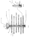
- a mounting system 1 for a balcony railing has tubular posts 2, 3, 4, each with a central anchor 5 on the floor (not shown) are attached.
- the tubular posts 2, 3, 4 are made of metal, in particular stainless steel Type designation V2A with a diameter of approx. 150 mm and a thickness of the tube wall 7 of 2 mm.
- the tubular post 3 is a middle post with opposite circumferential bores 6 and tubular posts 2, 4 are as corner posts with circumferential holes 6 at a 90 ° angle and / or end post one-sided circumferential bores 6 formed.
- the circumferential holes 6 are radially directed through holes with a diameter of approx. 45 mm in the tube wall 7 with equal distances of approx. 150 mm to each other.
- Plug connections 8 in the circumferential bores 6 of the posts 2, 3, 4 are designed as rubber bearings with a evaporating lubricant from a liquid that preferably contains alcohol for improved evaporation.
- a evaporating lubricant from a liquid that preferably contains alcohol for improved evaporation.
- Fig. 2 Corresponding features from Fig. 1 are with corresponding reference numerals named.
- the central one Anchoring 5 to the floor is done with a threaded bolt 10 in a dowel (not shown) in one vertical bore, e.g. B. in a concrete slab as the floor a balcony, the tubular post 2, 3, 4 the central anchoring 5 inside completely surrounds.
- tubular post 2, 3, 4 is near its lower A cross-shaped end at the inner circumference Profile 11 with a centrally welded washer 12 welded.
- Particularly long tubular posts 2, 3, 4 are near their upper end on the inner circumference with the cross-shaped profile 11 with a central welded disc 12 provided.
- a mother 13 as a screw connection is anchored to the ground Threaded bolt 10 can be screwed on for fastening the tubular posts 2, 3, 4 on the floor.
- Sealing ring 14 with a diameter of approx. 60 mm is around the threaded bolt 10 provided between profile 11 and the floor.
- Adjustment means as axial relative to the profile 11 and thus to the floor adjustable screws 15 are in Circumferentially spaced at 90 ° from each other between pipe wall 7 and sealing ring 14 on the with inner circumference welded profile 11 provided for Align the tubular posts 2, 3, 4 in the event of unevenness on the ground.
- the tubular posts 2, 3, 4 are all over Extent of the tube wall 7 from the bottom through one each Sealing profile 32 insulated.
- Fig. 3 Corresponding features from Fig. 1 are with corresponding reference numerals named.
- the connecting rods 9 have 18 radial through holes at their ends 19 on.
- a securing element 16 can be within and axially to the tubular posts 2, 3, 4 in the radial through holes 19 are inserted and secures the connecting rods 9, so that even when Failure of the plug connections 8, the connecting rods 9 be held in a form-fitting manner in the circumferential bores 6.
- the rubber bearings 8 are with a radial groove 17 on the Pipe wall 7 mounted.
- the clear diameter of the rubber bearings 8 is so on the diameter of the connecting rods 9 matched that the connecting rods 9 only with Lubricant axially movable in the tubular post 2, 3, 4 are relative to the rubber bearing 8.
- FIG. 4 Corresponding features from Fig. 1 are with corresponding reference numerals named.
- a lid 20 is with a protrusion on the tubular posts 2, 3, 4 attachable and with countersunk screws 21 on the tubular Posts 2, 3, 4 attachable.
- FIGS. 1 and 4 Corresponding features from FIGS. 1 and 4 are named with corresponding reference numerals.
- On the lid 20 is on the tubular posts 2, 3, 4 over a rubber bearing 8 an umbrella holder 22 pivotable mounted by the cover 20 rotatable on a central tube 23 is stored with the central anchorage 5 is screwed to the floor.
- the umbrella holder 22 is equipped with an adjustment 24.
- FIGS. 1, 4 and 5 Corresponding features from FIGS. 1, 4 and 5 are named with the corresponding reference symbols.
- On the Cover 20 is a half-shell 25 via a rubber bearing 8 stainless steel mounted by cover 20 connected to a drain through central tube 23 is, which opens into an outlet 26, each over one Rubber bearings 8 out of the tubular posts 2, 3, 4 is.
- FIG. 7a Corresponding features from FIG. 1 are included corresponding reference numerals named.
- the shell 27 is in its dimensions adapted for example to standard railings.
- the plane-parallel planes 30, 31 are thus from one another spaced that they are prestressed on the connecting rods 9 concerns.
- tubular posts 2, 3, 4 are to be set, holes are vertical brought to the floor and dowels placed. In the dowels the threaded bolts 10 of the central anchorage 5 screwed. Be on the central anchorages 5 Sealing rings 14 and the tubular posts 2, 3, 4 with Sealing profile 15 set. The tubular posts 2, 3, 4 are with the relative to the profile 11 and thus to the floor adjustable set screws 15 preferably vertically aligned.
- One nut 13 each as a screw connection is on the threaded bolt anchored in the ground 10 from above through the tubular posts 2, 3, 4 with an extended socket wrench can be screwed on Attach each tubular post 2, 3, 4 on Ground.
- the tubular posts 2, 3, 4 are with their Circumferential bores 6 aligned with each other.
- Connecting rods 9 are through the tight-fitting rubber bearings 8 so far in the tubular posts 2, 3, 4 inserted until the other End of the connecting rods 9 in the circumferential bores 6 of the opposite tubular posts 2, 3, 4 can be inserted. After insertion the connecting rods 9 are averaged so that the Projection of the connecting rods 9 in the interior of the opposite lying tubular posts 2, 3, 4 on both Ends is about the same. The connecting rods 9 are rotated in the rubber bearings 8 so that their radial Through holes 19 at the ends 18 with each other are aligned.
- a security element 16 becomes inside and axially of the tubular posts 2, 3, 4 in the radial through holes 19 introduced and secures the connecting rods 9. After the evaporation of the lubricant on the rubber bearings 8 the connecting rods 9 are no longer displaceable relative to the rubber bearings 8.
- Cover 20 are with Protrusion placed on the tubular posts 2, 3, 4 and with countersunk screws 21 on the tubular Posts 2, 3, 4 attached.
- an umbrella holder 22 can be pivoted or a half-shell 25 can be mounted.
- Rigid shells 27 are 29 at their free ends slightly bent up and the two parallel to each other Levels 30, 31 made of rigid plastic from above slipped over the connecting rods 9 until the apex 28 of the rigid shells 27 on the top connecting rod 9 rest and the free ends 29 to the system can be relaxed on the connecting rods 9.
Landscapes
- Engineering & Computer Science (AREA)
- Architecture (AREA)
- Civil Engineering (AREA)
- Structural Engineering (AREA)
- Bridges Or Land Bridges (AREA)
- Joining Of Building Structures In Genera (AREA)
- Automobile Manufacture Line, Endless Track Vehicle, Trailer (AREA)
- Butt Welding And Welding Of Specific Article (AREA)
- Medicines Containing Plant Substances (AREA)
- Refuge Islands, Traffic Blockers, Or Guard Fence (AREA)
- Devices Affording Protection Of Roads Or Walls For Sound Insulation (AREA)
Abstract
Description
- Fig. 1:
- eine Ansicht eines Montagesystems als Geländer mit drei Pfosten gemäß der Erfindung,
- Fig. 2:
- einen Querschnitt durch eine zentrale Verankerung eines Pfostens gemäß der Erfindung,
- Fig. 3:
- einen Querschnitt durch eine Steckverbindung eines Pfostens gemäß der Erfindung,
- Fig. 4:
- eine Draufsicht auf einen Pfosten gemäß der Erfindung,
- Fig. 5:
- eine Ansicht einer Ausgestaltung eines Montagesystems gemäß der Erfindung,
- Fig. 6:
- eine Ansicht einer alternativen Ausgestaltung eines Montagesystems gemäß der Erfindung,
- Fig. 6a:
- eine Detailansicht von Fig. 6,
- Fig. 7:
- eine Ansicht eines Montagesystems gemäß der Erfindung, und
- Fig. 7a:
- eine Seitenansicht von Fig. 7.
Claims (10)
- Montagesystem (1) für Geländer, Sperrgitter oder Sprossenwände mit mindestens zwei rohrförmigen Pfosten (2, 3, 4) mit jeweils einer zentralen Verankerung (5) am Boden, Verbindungsstäben (9) zwischen benachbarten Pfosten (2, 3, 4) und Steckverbindungen (8) in Umfangsbohrungen (6) der Pfosten (2, 3, 4), in denen die Verbindungsstäbe (9) jeweils mit beiden Enden (18) gehalten sind.
- Montagesystem (1) gemäß Anspruch 1, dadurch gekennzeichnet, dass für die zentrale Verankerung (5) am Boden eine Schraubverbindung (13) an einem mit einem inneren Umfang (7) des rohrförmigen Pfostens (2, 3, 4) verschweißten Profil (11) vorgesehen ist, die Schraubverbindung (13) auf einen Bolzen (10) im Boden aufschraubbar und ein Dichtring (14) um den Bolzen (10) zwischen dem Profil (11) und dem Boden vorgesehen ist.
- Montagesystem (1) gemäß Anspruch 2, dadurch gekennzeichnet, dass Justiermittel (15), insbesondere Stellschrauben, an dem mit dem inneren Umfang (7) der rohrförmigen Pfosten (2, 3, 4) verschweißten Profil (11) vorgesehen sind.
- Montagesystem (11) gemäß Anspruch 1, dadurch gekennzeichnet, dass die Umfangsbohrungen (6) der Pfosten (2, 3, 4) mit 180° und oder 90° zueinander versetzt sind.
- Montagesystem (1) gemäß Anspruch 1, dadurch gekennzeichnet, dass die Steckverbindungen (8) in den Umfangsbohrungen (6) der Pfosten (2, 3, 4) in axialer Richtung der Verbindungsstäbe (9) reibschlüssig und in radialer Richtung der Verbindungsstäbe (9) formschlüssig sind.
- Montagesystem (1) gemäß Anspruch 1, dadurch gekennzeichnet, dass die Steckverbindungen (8) in den Umfangsbohrungen (6) der Pfosten (2, 3, 4) mit einem verdunstbaren Gleitmittel versehen sind.
- Montagesystem (1) gemäß Anspruch 1, dadurch gekennzeichnet, dass ein Sicherungselement (16) vorgesehen ist, mit dem die Verbindungsstäbe (9) innerhalb eines rohrförmigen Pfosten (2, 3, 4) sicherbar sind.
- Montagesystem (1) gemäß Anspruch 1, dadurch gekennzeichnet, dass die rohrförmigen Pfosten (2, 3, 4) jeweils auf einem Dichtprofil (32) montierbar sind.
- Montagesystem (1) gemäß Anspruch 1, dadurch gekennzeichnet, dass die rohrförmigen Pfosten (2, 3, 4) jeweils mit einem Deckel (20) verschließbar sind und ein Zentralrohr (23) vorgesehen ist, das an der Schraubverbindung (13), am Profil (11) und am Dekkel (20) befestigbar ist und Aufbauten, wie Blumenbehälter (25) oder drehbar gelagerte Schirmhalterungen (22) vorgesehen sind, die durch den Deckel (20) am Zentralrohr (23) gelagert sind.
- Montagesystem (11) gemäß Anspruch 1, dadurch gekennzeichnet, dass eine biegesteife Schale (27) aus zwei im wesentlichen zueinander planparallelen Ebenen (30, 31) vorgesehen ist, die als Hülle über die Verbindungsstäbe (9) spannbar ist.
Priority Applications (7)
| Application Number | Priority Date | Filing Date | Title |
|---|---|---|---|
| EP02027471A EP1428956B1 (de) | 2002-12-10 | 2002-12-10 | Montagesystem für Geländer, etc. |
| DE50208858T DE50208858D1 (de) | 2002-12-10 | 2002-12-10 | Montagesystem für Geländer, etc. |
| AT02027471T ATE347000T1 (de) | 2002-12-10 | 2002-12-10 | Montagesystem für geländer, etc. |
| ES02027471T ES2277982T3 (es) | 2002-12-10 | 2002-12-10 | Sistema de montaje para barandillas. |
| AU2003289827A AU2003289827A1 (en) | 2002-12-10 | 2003-12-08 | Assembly system for railings etc. |
| DE10394140T DE10394140D2 (de) | 2002-12-10 | 2003-12-08 | Montagesystem für Geländer, etc. |
| PCT/DE2003/004031 WO2004053253A2 (de) | 2002-12-10 | 2003-12-08 | Montagesystem für geländer, etc. |
Applications Claiming Priority (1)
| Application Number | Priority Date | Filing Date | Title |
|---|---|---|---|
| EP02027471A EP1428956B1 (de) | 2002-12-10 | 2002-12-10 | Montagesystem für Geländer, etc. |
Publications (2)
| Publication Number | Publication Date |
|---|---|
| EP1428956A1 true EP1428956A1 (de) | 2004-06-16 |
| EP1428956B1 EP1428956B1 (de) | 2006-11-29 |
Family
ID=32319561
Family Applications (1)
| Application Number | Title | Priority Date | Filing Date |
|---|---|---|---|
| EP02027471A Expired - Lifetime EP1428956B1 (de) | 2002-12-10 | 2002-12-10 | Montagesystem für Geländer, etc. |
Country Status (6)
| Country | Link |
|---|---|
| EP (1) | EP1428956B1 (de) |
| AT (1) | ATE347000T1 (de) |
| AU (1) | AU2003289827A1 (de) |
| DE (2) | DE50208858D1 (de) |
| ES (1) | ES2277982T3 (de) |
| WO (1) | WO2004053253A2 (de) |
Citations (6)
| Publication number | Priority date | Publication date | Assignee | Title |
|---|---|---|---|---|
| US3700213A (en) * | 1971-02-12 | 1972-10-24 | Pioneer Plastics Inc | Plastic fence |
| US4540160A (en) * | 1984-03-28 | 1985-09-10 | Zanavich James K | Rail fence |
| US4702459A (en) * | 1986-10-30 | 1987-10-27 | Moschner Vernon D | Fence assembly |
| US5332196A (en) * | 1992-12-30 | 1994-07-26 | Wright Richard P | Fence post end cap |
| US6141928A (en) * | 1999-02-08 | 2000-11-07 | Platt; Robert E. | Post mount |
| US20020139967A1 (en) * | 2001-03-30 | 2002-10-03 | Calverley Anthony R. | Aluminum shadow box fence |
-
2002
- 2002-12-10 AT AT02027471T patent/ATE347000T1/de active
- 2002-12-10 DE DE50208858T patent/DE50208858D1/de not_active Expired - Lifetime
- 2002-12-10 EP EP02027471A patent/EP1428956B1/de not_active Expired - Lifetime
- 2002-12-10 ES ES02027471T patent/ES2277982T3/es not_active Expired - Lifetime
-
2003
- 2003-12-08 WO PCT/DE2003/004031 patent/WO2004053253A2/de not_active Ceased
- 2003-12-08 AU AU2003289827A patent/AU2003289827A1/en not_active Abandoned
- 2003-12-08 DE DE10394140T patent/DE10394140D2/de not_active Expired - Fee Related
Patent Citations (6)
| Publication number | Priority date | Publication date | Assignee | Title |
|---|---|---|---|---|
| US3700213A (en) * | 1971-02-12 | 1972-10-24 | Pioneer Plastics Inc | Plastic fence |
| US4540160A (en) * | 1984-03-28 | 1985-09-10 | Zanavich James K | Rail fence |
| US4702459A (en) * | 1986-10-30 | 1987-10-27 | Moschner Vernon D | Fence assembly |
| US5332196A (en) * | 1992-12-30 | 1994-07-26 | Wright Richard P | Fence post end cap |
| US6141928A (en) * | 1999-02-08 | 2000-11-07 | Platt; Robert E. | Post mount |
| US20020139967A1 (en) * | 2001-03-30 | 2002-10-03 | Calverley Anthony R. | Aluminum shadow box fence |
Also Published As
| Publication number | Publication date |
|---|---|
| DE10394140D2 (de) | 2005-12-08 |
| WO2004053253A2 (de) | 2004-06-24 |
| EP1428956B1 (de) | 2006-11-29 |
| ES2277982T3 (es) | 2007-08-01 |
| ATE347000T1 (de) | 2006-12-15 |
| AU2003289827A8 (en) | 2004-06-30 |
| DE50208858D1 (de) | 2007-01-11 |
| WO2004053253A3 (de) | 2004-09-16 |
| AU2003289827A1 (en) | 2004-06-30 |
Similar Documents
| Publication | Publication Date | Title |
|---|---|---|
| WO1985003731A1 (fr) | Installation de fixation au sol | |
| EP1396594B1 (de) | Befestigungsvorrichtung für Pfosten | |
| DE9208144U1 (de) | Pfostenträger, insbesondere für die Holzstützen von Balkonen, Pergolen, Carports, Blockhäusern o.dgl. | |
| DE202018103518U1 (de) | Vorrichtung zur Befestigung eines Aufbaus, insbesondere eines stab-, pfosten- oder rohrförmigen Gegenstandes | |
| DE3404947A1 (de) | Vorrichtung zur befestigung von rohren zwischen pfosten und/oder waenden | |
| EP1428956A1 (de) | Montagesystem für Geländer, etc. | |
| DE4309041A1 (de) | Säule für Geländer, Zäune oder dergleichen | |
| EP3336271A1 (de) | Befestigungsvorrichtung zur befestigung eines bauelements an einem eine dämmschicht aufweisenden bauteil | |
| EP1460277B1 (de) | Verankerungshülse für Schutzgeländer | |
| EP3473779B1 (de) | Verbindungselement mit feststellelement sowie verfahren zum feststellen des verbindungselements | |
| EP0152530B1 (de) | Bödenbefestigungsvorrichtung | |
| EP4029401B1 (de) | Vorrichtung und verfahren zur befestigung eines sonnenschirms | |
| DE102014006620B4 (de) | Verbindungsvorrichtung zur Verbindung von Montageelementen | |
| DE202011105347U1 (de) | Grab- oder Gedenksteinanordnung | |
| DE20215072U1 (de) | Absturzsicherung bei leicht geneigten Dächern und bei Flachdächern | |
| DE9313754U1 (de) | Sicherheitszaun | |
| DE19823220C1 (de) | Verankerungsmittel insbesondere für Balkonanbauten | |
| EP0911535B1 (de) | Verankerungseinheit mit Rückstellmittel | |
| DE29713525U1 (de) | Vorrichtung zum Aufstellen eines Mastes | |
| DE102018002140B4 (de) | Fangmastständer für einen Fangmast einer Blitzschutzanlage | |
| EP2166234A1 (de) | Grablaterne | |
| EP1524384A1 (de) | Montagesystem für Geländer | |
| DE20207662U1 (de) | Montageteil für die Befestigung eines Fallrohres | |
| DE102010039944B3 (de) | Haltevorrichtung | |
| DE19607556C2 (de) | Bausatz zum Befestigen von rohrförmigen Geländerstäben eines Treppengeländers an der Außenseite von Treppenstufen |
Legal Events
| Date | Code | Title | Description |
|---|---|---|---|
| PUAI | Public reference made under article 153(3) epc to a published international application that has entered the european phase |
Free format text: ORIGINAL CODE: 0009012 |
|
| AK | Designated contracting states |
Kind code of ref document: A1 Designated state(s): AT BE BG CH CY CZ DE DK EE ES FI FR GB GR IE IT LI LU MC NL PT SE SI SK TR |
|
| AX | Request for extension of the european patent |
Extension state: AL LT LV MK RO |
|
| RAP1 | Party data changed (applicant data changed or rights of an application transferred) |
Owner name: SALZMANN, ANJA |
|
| AKX | Designation fees paid | ||
| REG | Reference to a national code |
Ref country code: DE Ref legal event code: 8566 |
|
| 17P | Request for examination filed |
Effective date: 20050311 |
|
| RBV | Designated contracting states (corrected) |
Designated state(s): AT BE BG CH CY CZ DE DK EE ES FI FR GB GR IE IT LI LU MC NL PT SE SK TR |
|
| RBV | Designated contracting states (corrected) |
Designated state(s): AT BE BG CH CY CZ DE DK EE ES FI FR GB GR IE IT LI LU MC NL PT SE SI SK TR |
|
| GRAP | Despatch of communication of intention to grant a patent |
Free format text: ORIGINAL CODE: EPIDOSNIGR1 |
|
| GRAS | Grant fee paid |
Free format text: ORIGINAL CODE: EPIDOSNIGR3 |
|
| GRAA | (expected) grant |
Free format text: ORIGINAL CODE: 0009210 |
|
| AK | Designated contracting states |
Kind code of ref document: B1 Designated state(s): AT BE BG CH CY CZ DE DK EE ES FI FR GB GR IE IT LI LU MC NL PT SE SI SK TR |
|
| PG25 | Lapsed in a contracting state [announced via postgrant information from national office to epo] |
Ref country code: CZ Free format text: LAPSE BECAUSE OF FAILURE TO SUBMIT A TRANSLATION OF THE DESCRIPTION OR TO PAY THE FEE WITHIN THE PRESCRIBED TIME-LIMIT Effective date: 20061129 Ref country code: SI Free format text: LAPSE BECAUSE OF FAILURE TO SUBMIT A TRANSLATION OF THE DESCRIPTION OR TO PAY THE FEE WITHIN THE PRESCRIBED TIME-LIMIT Effective date: 20061129 Ref country code: FI Free format text: LAPSE BECAUSE OF FAILURE TO SUBMIT A TRANSLATION OF THE DESCRIPTION OR TO PAY THE FEE WITHIN THE PRESCRIBED TIME-LIMIT Effective date: 20061129 Ref country code: SK Free format text: LAPSE BECAUSE OF FAILURE TO SUBMIT A TRANSLATION OF THE DESCRIPTION OR TO PAY THE FEE WITHIN THE PRESCRIBED TIME-LIMIT Effective date: 20061129 Ref country code: NL Free format text: LAPSE BECAUSE OF FAILURE TO SUBMIT A TRANSLATION OF THE DESCRIPTION OR TO PAY THE FEE WITHIN THE PRESCRIBED TIME-LIMIT Effective date: 20061129 Ref country code: IE Free format text: LAPSE BECAUSE OF FAILURE TO SUBMIT A TRANSLATION OF THE DESCRIPTION OR TO PAY THE FEE WITHIN THE PRESCRIBED TIME-LIMIT Effective date: 20061129 |
|
| REG | Reference to a national code |
Ref country code: GB Ref legal event code: FG4D Free format text: NOT ENGLISH |
|
| RIN1 | Information on inventor provided before grant (corrected) |
Inventor name: SALZMANN, KARL |
|
| REG | Reference to a national code |
Ref country code: CH Ref legal event code: EP |
|
| PG25 | Lapsed in a contracting state [announced via postgrant information from national office to epo] |
Ref country code: MC Free format text: LAPSE BECAUSE OF NON-PAYMENT OF DUE FEES Effective date: 20061231 Ref country code: BE Free format text: LAPSE BECAUSE OF NON-PAYMENT OF DUE FEES Effective date: 20061231 |
|
| REG | Reference to a national code |
Ref country code: IE Ref legal event code: FG4D Free format text: LANGUAGE OF EP DOCUMENT: GERMAN |
|
| REF | Corresponds to: |
Ref document number: 50208858 Country of ref document: DE Date of ref document: 20070111 Kind code of ref document: P |
|
| PG25 | Lapsed in a contracting state [announced via postgrant information from national office to epo] |
Ref country code: BG Free format text: LAPSE BECAUSE OF FAILURE TO SUBMIT A TRANSLATION OF THE DESCRIPTION OR TO PAY THE FEE WITHIN THE PRESCRIBED TIME-LIMIT Effective date: 20070228 Ref country code: SE Free format text: LAPSE BECAUSE OF FAILURE TO SUBMIT A TRANSLATION OF THE DESCRIPTION OR TO PAY THE FEE WITHIN THE PRESCRIBED TIME-LIMIT Effective date: 20070228 Ref country code: DK Free format text: LAPSE BECAUSE OF FAILURE TO SUBMIT A TRANSLATION OF THE DESCRIPTION OR TO PAY THE FEE WITHIN THE PRESCRIBED TIME-LIMIT Effective date: 20070228 |
|
| RAP2 | Party data changed (patent owner data changed or rights of a patent transferred) |
Owner name: HARALD BOEHL GMBH |
|
| GBT | Gb: translation of ep patent filed (gb section 77(6)(a)/1977) |
Effective date: 20070305 |
|
| REG | Reference to a national code |
Ref country code: GB Ref legal event code: 732E |
|
| PG25 | Lapsed in a contracting state [announced via postgrant information from national office to epo] |
Ref country code: PT Free format text: LAPSE BECAUSE OF FAILURE TO SUBMIT A TRANSLATION OF THE DESCRIPTION OR TO PAY THE FEE WITHIN THE PRESCRIBED TIME-LIMIT Effective date: 20070430 |
|
| NLT2 | Nl: modifications (of names), taken from the european patent patent bulletin |
Owner name: HARALD BOEHL GMBH Effective date: 20070314 |
|
| NLV1 | Nl: lapsed or annulled due to failure to fulfill the requirements of art. 29p and 29m of the patents act | ||
| REG | Reference to a national code |
Ref country code: IE Ref legal event code: FD4D |
|
| REG | Reference to a national code |
Ref country code: CH Ref legal event code: PUE Owner name: HARALD BOEHL GMBH Free format text: SALZMANN, ANJA#WAHLHEIMER HOF 28 A#55278 HAHNHEIM (DE) -TRANSFER TO- HARALD BOEHL GMBH#WILLERSHAEUSER STRASSE 16#35119 ROSENTHAL (DE) Ref country code: CH Ref legal event code: NV Representative=s name: PA ALDO ROEMPLER |
|
| EN | Fr: translation not filed | ||
| REG | Reference to a national code |
Ref country code: ES Ref legal event code: FG2A Ref document number: 2277982 Country of ref document: ES Kind code of ref document: T3 |
|
| PLBE | No opposition filed within time limit |
Free format text: ORIGINAL CODE: 0009261 |
|
| STAA | Information on the status of an ep patent application or granted ep patent |
Free format text: STATUS: NO OPPOSITION FILED WITHIN TIME LIMIT |
|
| 26N | No opposition filed |
Effective date: 20070830 |
|
| BERE | Be: lapsed |
Owner name: SALZMANN, ANJA Effective date: 20061231 |
|
| PG25 | Lapsed in a contracting state [announced via postgrant information from national office to epo] |
Ref country code: FR Free format text: LAPSE BECAUSE OF FAILURE TO SUBMIT A TRANSLATION OF THE DESCRIPTION OR TO PAY THE FEE WITHIN THE PRESCRIBED TIME-LIMIT Effective date: 20070720 Ref country code: GR Free format text: LAPSE BECAUSE OF FAILURE TO SUBMIT A TRANSLATION OF THE DESCRIPTION OR TO PAY THE FEE WITHIN THE PRESCRIBED TIME-LIMIT Effective date: 20070301 |
|
| PG25 | Lapsed in a contracting state [announced via postgrant information from national office to epo] |
Ref country code: EE Free format text: LAPSE BECAUSE OF FAILURE TO SUBMIT A TRANSLATION OF THE DESCRIPTION OR TO PAY THE FEE WITHIN THE PRESCRIBED TIME-LIMIT Effective date: 20061129 |
|
| PG25 | Lapsed in a contracting state [announced via postgrant information from national office to epo] |
Ref country code: LU Free format text: LAPSE BECAUSE OF NON-PAYMENT OF DUE FEES Effective date: 20061210 Ref country code: TR Free format text: LAPSE BECAUSE OF FAILURE TO SUBMIT A TRANSLATION OF THE DESCRIPTION OR TO PAY THE FEE WITHIN THE PRESCRIBED TIME-LIMIT Effective date: 20061129 |
|
| REG | Reference to a national code |
Ref country code: CH Ref legal event code: PCAR Free format text: ALDO ROEMPLER PATENTANWALT;BRENDENWEG 11 POSTFACH 154;9424 RHEINECK (CH) |
|
| PG25 | Lapsed in a contracting state [announced via postgrant information from national office to epo] |
Ref country code: CY Free format text: LAPSE BECAUSE OF FAILURE TO SUBMIT A TRANSLATION OF THE DESCRIPTION OR TO PAY THE FEE WITHIN THE PRESCRIBED TIME-LIMIT Effective date: 20061129 Ref country code: FR Free format text: LAPSE BECAUSE OF FAILURE TO SUBMIT A TRANSLATION OF THE DESCRIPTION OR TO PAY THE FEE WITHIN THE PRESCRIBED TIME-LIMIT Effective date: 20061129 |
|
| PGFP | Annual fee paid to national office [announced via postgrant information from national office to epo] |
Ref country code: AT Payment date: 20101214 Year of fee payment: 9 |
|
| PGFP | Annual fee paid to national office [announced via postgrant information from national office to epo] |
Ref country code: IT Payment date: 20101223 Year of fee payment: 9 |
|
| PGFP | Annual fee paid to national office [announced via postgrant information from national office to epo] |
Ref country code: CH Payment date: 20111227 Year of fee payment: 10 |
|
| REG | Reference to a national code |
Ref country code: DE Ref legal event code: R082 Ref document number: 50208858 Country of ref document: DE Representative=s name: PATENTANWAELTE OLBRICHT, BUCHHOLD, KEULERTZ PA, DE |
|
| PG25 | Lapsed in a contracting state [announced via postgrant information from national office to epo] |
Ref country code: IT Free format text: LAPSE BECAUSE OF NON-PAYMENT OF DUE FEES Effective date: 20111210 |
|
| REG | Reference to a national code |
Ref country code: AT Ref legal event code: MM01 Ref document number: 347000 Country of ref document: AT Kind code of ref document: T Effective date: 20111210 |
|
| PG25 | Lapsed in a contracting state [announced via postgrant information from national office to epo] |
Ref country code: AT Free format text: LAPSE BECAUSE OF NON-PAYMENT OF DUE FEES Effective date: 20111210 |
|
| PGFP | Annual fee paid to national office [announced via postgrant information from national office to epo] |
Ref country code: GB Payment date: 20121220 Year of fee payment: 11 |
|
| PGFP | Annual fee paid to national office [announced via postgrant information from national office to epo] |
Ref country code: ES Payment date: 20121226 Year of fee payment: 11 |
|
| REG | Reference to a national code |
Ref country code: CH Ref legal event code: PL |
|
| PG25 | Lapsed in a contracting state [announced via postgrant information from national office to epo] |
Ref country code: LI Free format text: LAPSE BECAUSE OF NON-PAYMENT OF DUE FEES Effective date: 20121231 Ref country code: CH Free format text: LAPSE BECAUSE OF NON-PAYMENT OF DUE FEES Effective date: 20121231 |
|
| GBPC | Gb: european patent ceased through non-payment of renewal fee |
Effective date: 20131210 |
|
| PG25 | Lapsed in a contracting state [announced via postgrant information from national office to epo] |
Ref country code: GB Free format text: LAPSE BECAUSE OF NON-PAYMENT OF DUE FEES Effective date: 20131210 |
|
| REG | Reference to a national code |
Ref country code: ES Ref legal event code: FD2A Effective date: 20150327 |
|
| PG25 | Lapsed in a contracting state [announced via postgrant information from national office to epo] |
Ref country code: ES Free format text: LAPSE BECAUSE OF NON-PAYMENT OF DUE FEES Effective date: 20131211 |
|
| PGFP | Annual fee paid to national office [announced via postgrant information from national office to epo] |
Ref country code: DE Payment date: 20211231 Year of fee payment: 20 |
|
| REG | Reference to a national code |
Ref country code: DE Ref legal event code: R071 Ref document number: 50208858 Country of ref document: DE |