EP1428717B1 - Sitzverstellschalter - Google Patents
Sitzverstellschalter Download PDFInfo
- Publication number
- EP1428717B1 EP1428717B1 EP03400063A EP03400063A EP1428717B1 EP 1428717 B1 EP1428717 B1 EP 1428717B1 EP 03400063 A EP03400063 A EP 03400063A EP 03400063 A EP03400063 A EP 03400063A EP 1428717 B1 EP1428717 B1 EP 1428717B1
- Authority
- EP
- European Patent Office
- Prior art keywords
- switch
- seat adjustment
- button
- quadrant
- adjustment switch
- Prior art date
- Legal status (The legal status is an assumption and is not a legal conclusion. Google has not performed a legal analysis and makes no representation as to the accuracy of the status listed.)
- Expired - Lifetime
Links
- 230000008878 coupling Effects 0.000 description 1
- 238000010168 coupling process Methods 0.000 description 1
- 238000005859 coupling reaction Methods 0.000 description 1
- 230000000717 retained effect Effects 0.000 description 1
Images


Classifications
-
- B—PERFORMING OPERATIONS; TRANSPORTING
- B60—VEHICLES IN GENERAL
- B60N—SEATS SPECIALLY ADAPTED FOR VEHICLES; VEHICLE PASSENGER ACCOMMODATION NOT OTHERWISE PROVIDED FOR
- B60N2/00—Seats specially adapted for vehicles; Arrangement or mounting of seats in vehicles
- B60N2/02—Seats specially adapted for vehicles; Arrangement or mounting of seats in vehicles the seat or part thereof being movable, e.g. adjustable
- B60N2/0224—Non-manual adjustments, e.g. with electrical operation
- B60N2/0226—User interfaces specially adapted for seat adjustment
- B60N2/0228—Hand-activated mechanical switches
-
- H—ELECTRICITY
- H01—ELECTRIC ELEMENTS
- H01H—ELECTRIC SWITCHES; RELAYS; SELECTORS; EMERGENCY PROTECTIVE DEVICES
- H01H25/00—Switches with compound movement of handle or other operating part
- H01H25/002—Switches with compound movement of handle or other operating part having an operating member rectilinearly slidable in different directions
-
- H—ELECTRICITY
- H01—ELECTRIC ELEMENTS
- H01H—ELECTRIC SWITCHES; RELAYS; SELECTORS; EMERGENCY PROTECTIVE DEVICES
- H01H2300/00—Orthogonal indexing scheme relating to electric switches, relays, selectors or emergency protective devices covered by H01H
- H01H2300/008—Application power seats
Definitions
- the invention relates to a Wegverstellschalter for a motor vehicle, with two keys which are longitudinally displaceable against each other and coupled together in the transverse direction to a switch housing, having the features of the preamble of claim 1.
- the DE 39 333 561 C is a Wegverstellschalter with the features of the preamble known.
- the 39 27 037 A shows an electrical switch assembly with an actuating member and an adjustable held it switching element.
- the US 5,844,182 shows several via control elements coupled to each other switching modules. From the DE 197 28 743 C the attachment of an operating element to spherical ends having tappets of the switching modules is known.
- the invention is therefore based on the object to provide a Wegverstellschalter, which is equally easy to use, but manages with a smaller number of components and in which the control is independent of the switch.
- the four-quadrant switches have a total of eight adjustment directions, so that the two buttons can each be adjusted in four directions. Compared to the prior art according to the DE 198 44 333 C1 a microswitch is saved, but all functions are retained. In addition, the four-quadrant switch is a separately manageable component and only has to be soldered onto a circuit board, for example. The four-quadrant switch will not, As in the above-mentioned prior art, built within the Wegverstellschalters, so that problems regarding tolerances to be set are avoided.
- each key or its contact piece has a receptacle for an actuating element of the four-quadrant switch.
- the key is coupled to the four-quadrant switch, so that the switching commands can be passed directly to the four-quadrant switch.
- the receptacle in particular has a cylindrical, eg circular cylindrical sleeve.
- the actuating element is an actuating tappet with a spherical free end. The spherical free end can be easily inserted into the circular cylindrical sleeve, and the movements of the key are transferred from a plane to a circular path.
- the spherical free end is inserted without play in the receiving sleeve, can be switched very precisely.
- the spherical free end is latched onto the plunger and is formed by a separate component. In this way, four-quadrant switches can be used, the actuating tappet is designed as desired.
- the two four-quadrant switches sit on a common board. By this measure it is ensured that the two switches have a defined position to each other and thus not only switching forces can be transmitted, but also holding forces for other components of Wegverstellschalters, in particular for attaching these components.
- Each key preferably has a control element projecting beyond the switch housing and a contact piece provided on the rear side of a housing wall.
- the operating element and / or the contact piece passes through the housing wall via an opening.
- the control element and the contact piece are connected to one another via a latch.
- the operating movement which acts on the operating element on the Wegverstellschalter, transmitted to the interior of the switch housing and arranged in the switch housing four-quadrant switch.
- the longitudinal slots in the housing wall ensure that the operating elements and / or the contact pieces, which pass through the housing wall via the longitudinal slot, do not tip over.
- the keys are longitudinally interleaved with one another slidably guided.
- the switching pieces are displaced in the longitudinal direction against each other, whereas a switching piece is mounted in the transverse direction nearly free of play in the other switching piece.
- a seat adjustment switch is shown as a whole, as used in motor vehicles, for example.
- This Wegverstellschalter 10 has a switch housing 12 with a housing wall 14 which is mounted on a circuit board 16.
- the board 16 may be connected directly or via further components to the housing 12.
- the housing wall 14 has a stepped opening 18, which has two longitudinally extending portions 20 and 22 and a transversely, the two sections 20 and 22 connecting third portion 24.
- the keys are 26 and 28 on the outside of the housing wall 14, whereas on the opposite inside of the housing wall 14, that is, in the interior of the switch housing 12, two switching pieces 30 and 32 are provided.
- Each switching piece 30 and 32 has a projecting in the direction of the associated button 26 and 28 locking piece 34 and 36, in which a latching tongue 38 and 40 of the respective button 26 and 28 can engage.
- the buttons 26 and 28 consist of a shell support 42 and a shell 44. In this case, the shell can be adapted to the interior of the motor vehicle with respect to material and / or color.
- the two switching pieces 30 and 32 have at their rear side, that is, on their side facing away from the keys 26 and 28, two receptacles 46 and 48 on ( FIG. 3 ), which are formed as a receiving sleeve 50 and 52, and in each of which a spherical free end 54 and 56 of a four-quadrant switch 58 and 60 is added.
- the spherical free ends 54 and 56 are formed as alsstastbare on the actuating plunger 64 and 66 of the four-quadrant switches 58 and 60 components 62.
- the directions of movement of the keys 26 and 28 are shown in detail.
- the button 28 in the longitudinal direction forward (arrow 68) or longitudinally to the rear (arrow 70) are operated independently of the button 26.
- the button 26 can be moved in the direction of the arrow 72 to the front or in the direction of the arrow 74 to the rear, regardless of the button 28.
- the direction of the arrow 76 only the two front parts of the keys 26 and 28 are moved together which also applies in the direction of the arrow 78, which shows the direction down.
- the two buttons 26 and 28 can only be moved together in the direction of the arrows 80 and 82, wherein the rear part of a vehicle seat moves either upwards (arrow 80) or downwards (arrow 82).
- This longitudinal slot 84 only allows a shift of the contact piece 30 in the longitudinal direction, that is in the direction of arrows 72 and 74.
- the contact piece 32 can be moved independently of the contact piece 30 due to this longitudinal slot 84 in the direction of the arrows 68 and 70.
- FIG. 3 is designated by the reference numeral 86 of the receiving space for the contact piece 30 in the contact piece 32.
- the two switching pieces 30 and 32 in the transverse direction that is, in the direction of the arrows 76 to 82, can only be moved together, since they engage in almost no play in this direction. Since the switching pieces 30 and 32 are dimensioned relatively large, a tilting of the operating elements, which are additionally supported on the outer wall of the switch housing 12, prevented over it.
- FIG. 4 is also seen that in addition the shell support 42 of the key 26 has a sliding spring 88 which engages in a corresponding sliding groove 90 in the shell support 42 of the key 28.
- the track spring 88 and the slide groove 90 form another longitudinal guide.
- FIG. 2 shows by reference numerals 92 and 94 two points of attack, to which the two keys 26 and 28 are coupled to the four-quadrant switches 58 and 60. It can be clearly seen that the rear end of the button 28 is coupled to the four-quadrant switch 60 and the front end of the button 26 is coupled to the four-quadrant switch 58. The coupling does not take place directly, but via the two switching pieces 30 and 32nd
Landscapes
- Engineering & Computer Science (AREA)
- Human Computer Interaction (AREA)
- Aviation & Aerospace Engineering (AREA)
- Transportation (AREA)
- Mechanical Engineering (AREA)
- Switches With Compound Operations (AREA)
- Seats For Vehicles (AREA)
- Chairs For Special Purposes, Such As Reclining Chairs (AREA)
- Toilet Supplies (AREA)
- Chairs Characterized By Structure (AREA)
Description
- Die Erfindung betrifft einen Sitzverstellschalter für ein Kraftfahrzeug, mit zwei Tasten, die in Längsrichtung gegeneinander verschieblich und in Querrichtung miteinander gekoppelt an einem Schaltergehäuse befestigt sind, mit den Merkmalen des Oberbegriffs des Anspruchs 1.
- Aus der
DE 198 44 333 C ist ein elektrischer Sitzverstellschalter bekannt geworden, welcher mehrere Tasten aufweist. Dabei entsprechen die Tasten jeweils einem Sitzteil und sind sinnfällig auslenkbar. Dies bedeutet, dass die Taste in die Richtung auslenkbar ist, in welcher sich das entsprechende Sitzteil bewegen soll. Dieser bekannte Sitzverstellschalter weist jedoch den Nachteil auf, dass er aus einer Vielzahl von Bauteilen aufgebaut ist. - Aus der
DE 39 333 561 C ist ein Sitzverstellschalter mit den Merkmalen des Oberbegriffs bekannt. Die 39 27 037 A zeigt eine elektrische Schalteranordnung mit einem Betätigungsteil und einem daran verstellbar gehaltenen Schaltglied. DieUS 5,844,182 zeigt mehrere über Bedienelemente miteinander gekoppelte Schaltmodule. Aus derDE 197 28 743 C ist die Befestigung eines Bedienelements an sphärische Enden aufweisenden Stößeln der Schaltmodule bekannt. - Der Erfindung liegt daher die Aufgabe zugrunde, einen Sitzverstellschalter bereitzustellen, welcher gleichermaßen gut bedienbar ist, jedoch mit einer geringeren Anzahl an Bauteilen auskommt und bei dem das Bedienelement unabhängig vom Schalter ist.
- Diese Aufgabe wird erfindungsgemäß mit einem Sitzverstellschalter gelöst, der die Merkmale des Anspruchs 1 aufweist.
- Die Vierquadrantenschalter besitzen insgesamt acht Verstellrichtungen, so dass die beiden Tasten jeweils in vier Richtungen verstellt werden können. Gegenüber dem Stand der Technik gemäß der
DE 198 44 333 C1 wird ein Mikroschalter eingespart, wobei jedoch alle Funktionen beibehalten bleiben. Außerdem ist der Vierquadrantenschalter in sich ein separat handhabbares Bauteil und muss lediglich zum Beispiel auf eine Platine aufgelötet werden. Der Vierquadrantenschalter wird nicht, wie beim oben genannten Stand der Technik, innerhalb des Sitzverstellschalters aufgebaut, so dass Probleme hinsichtlich einzustellender Toleranzen vermieden werden. - Erfindungsgemäß weist jede Taste oder dessen Schaltstück eine Aufnahme für ein Betätigungselement des Vierquadrantenschalters auf. Über diese Aufnahme wird die Taste mit dem Vierquadrantenschalter gekoppelt, so dass die Schaltbefehle an den Vierquadrantenschalter direkt übergeben werden können. Eine einfache Montage wird dadurch gewährleistet, dass die Aufnahme insbesondere eine zylindrische, z.B. kreiszylindrische Hülse aufweist. Erfindungsgemäß ist das Betätigungselement ein Betätigungsstößel mit einem kugelförmigen freien Ende. Das kugelförmige freie Ende kann problemlos in die kreiszylindrische Hülse eingesetzt werden, und die Bewegungen der Taste werden aus einer Ebene auf eine Kreisbahn übertragen. Da das kugelförmige freie Ende spielfrei in die Aufnahmehülse eingesetzt ist, kann sehr präzise geschaltet werden. Erfindungsgemäß ist das kugelförmige freie Ende auf den Stößel aufgerastet und wird von einem separaten Bauteil gebildet. Auf diese Weise können Vierquadrantenschalter verwendet werden, deren Betätigungsstößel beliebig ausgebildet ist.
- Bei einer Weiterbildung ist vorgesehen, dass die beiden Vierquadrantenschalter auf einer gemeinsamen Platine sitzen. Durch diese Maßnahme wird gewährleistet, dass die beiden Schalter eine definierte Position zueinander aufweisen und somit nicht nur Schaltkräfte übertragen werden können, sondern auch Haltekräfte für andere Bauteile des Sitzverstellschalters, insbesondere zum Befestigen dieser Bauteile.
- Bevorzugt weist jede Taste ein das Schaltergehäuse überragendes Bedienelement und ein auf der Rückseite einer Gehäusewand vorgesehenes Schaltstück auf. Dabei durchgreift das Bedienelement und/oder das Schaltstück die Gehäusewand über einen Durchbruch. Das Bedienelement und das Schaltstück sind über eine Verrastung miteinander verbunden. Hierdurch wird die Bedienbewegung, die am Bedienelement auf den Sitzverstellschalter wirkt, in das Innere des Schaltergehäuses und auf die im Schaltergehäuse angeordneten Vierquadrantenschalter übertragen. Die Längsschlitze in der Gehäusewand gewährleisten, dass die Bedienelemente und/oder die Schaltstücke, welche die Gehäusewand über den Längsschlitz durchgreifen, nicht kippen.
- Bei einem bevorzugten Ausführungsbeispiel sind die Tasten über ineinander geschachtelte Schaltstücke in Längsrichtung verschiebbar geführt. Die Schaltstücke sind in Längsrichtung gegeneinander verlagerbar, wohingegen das eine Schaltstück in Querrichtung nahezu spielfrei im anderen Schaltstück gelagert ist.
- Weitere Vorteile, Merkmale und Einzelheiten der Erfindung ergeben sich aus den Unteransprüchen sowie der nachfolgenden Beschreibung, in der unter Bezugnahme auf die Zeichnung ein besonders bevorzugtes Ausführungsbeispiel im Einzelnen beschrieben ist. Dabei können die in der Zeichnung dargestellten sowie in den Ansprüchen und in der Beschreibung erwähnten Merkmale jeweils einzeln für sich oder in beliebiger Kombination erfindungswesentlich sein.
- In der Zeichnung zeigen:
- Figur 1
- eine Explosionsdarstellung des erfindungsgemäßen Sitzverstellschalters;
- Figur 2
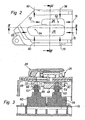
- eine Seitenansicht des Sitzverstellschalters;
- Figur 3
- einen Schnitt III-III gemäß
Figur 2 ; und - Figur 4
- einen Schnitt IV-IV gemäß
Figur 2 . - In der
Figur 1 ist mit dem Bezugszeichen 10 insgesamt ein Sitzverstellschalter dargestellt, wie er zum Beispiel in Kraftfahrzeugen verwendet wird. Dieser Sitzverstellschalter 10 weist ein Schaltergehäuse 12 mit einer Gehäusewand 14 auf, welches auf eine Platine 16 aufgesetzt ist. Dabei kann die Platine 16 direkt oder über weitere Bauteile mit dem Gehäuse 12 verbunden sein. Die Gehäusewand 14 weist einen gestuften Durchbruch 18 auf, der zwei in Längsrichtung verlaufende Abschnitte 20 und 22 und einen in Querrichtung, die beiden Abschnitte 20 und 22 verbindenden dritten Abschnitt 24, aufweist. Dabei befinden sich die Tasten 26 und 28 auf der Außenseite der Gehäusewand 14, wohingegen auf der gegenüberliegenden Innenseite der Gehäusewand 14, das heißt im Innern des Schaltergehäuses 12, zwei Schaltstücke 30 und 32 vorgesehen sind. Jedes Schaltstück 30 und 32 besitzt ein in Richtung der zugehörenden Taste 26 und 28 abragendes Raststück 34 und 36, in welches eine Rastzunge 38 und 40 der jeweiligen Taste 26 und 28 einrasten kann. Die Tasten 26 und 28 bestehen aus einem Schalenträger 42 sowie einer Schale 44. Dabei kann die Schale hinsichtlich Material und/oder Farbe dem Interieur des Kraftfahrzeugs angepasst sein. - Die beiden Schaltstücke 30 und 32 weisen an ihrer Rückseite, das heißt an ihrer den Tasten 26 und 28 abgewandten Seite, zwei Aufnahmen 46 und 48 auf (
Figur 3 ), die als Aufnahmehülse 50 und 52 ausgebildet sind, und in welche jeweils ein kugelförmiges freies Ende 54 und 56 eines Vierquadrantenschalters 58 und 60 aufgenommen ist. Die kugelförmigen freien Enden 54 und 56 sind als auf die Betätigungsstößel 64 und 66 der Vierquadrantenschalter 58 und 60 aufrastbare Bauteile 62 ausgebildet. - In der
Figur 2 sind die Bewegungsrichtungen der Tasten 26 und 28 im Einzelnen dargestellt. Dabei kann zum Beispiel die Taste 28 in Längsrichtung nach vorne (Pfeil 68) oder in Längsrichtung nach hinten (Pfeil 70) unabhängig von der Taste 26 betätigt werden. Ebenso kann die Taste 26 in Richtung des Pfeils 72 nach vorne beziehungsweise in Richtung des Pfeils 74 nach hinten bewegt werden, unabhängig von der Taste 28. In Richtung des Pfeils 76 können jedoch nur die beiden vorderen Teile der Tasten 26 und 28 gemeinsam bewegt werden, was auch in Richtung des Pfeils 78 gilt, der die Richtung nach unten zeigt. Dabei bewegt sich zum Beispiel der vordere Teil eines Fahrzeugsitzes nach oben (Pfeil 76) oder nach unten (Pfeil 78). Ebenso können die beiden Tasten 26 und 28 nur gemeinsam in Richtung der Pfeile 80 bzw. 82 bewegt werden, wobei sich der hintere Teil eines Fahrzeugsitzes entweder nach oben (Pfeil 80) oder nach unten (Pfeil 82) bewegt. - Dies wird dadurch bewirkt, dass die beiden Schaltstücke 30 und 32 ineinander geschachtelt sind, wobei das Schaltstück 30 im Schaltstück 32 geführt ist und das Raststück 34 das Schaltstück 32 über einen Längsschlitz 84 durchgreift. Dieser Längsschlitz 84 erlaubt lediglich eine Verschiebung des Schaltstückes 30 in Längsrichtung, das heißt in Richtung der Pfeile 72 und 74. Ebenso kann das Schaltstück 32 unabhängig vom Schaltstück 30 aufgrund dieses Längsschlitzes 84 in Richtung der Pfeile 68 und 70 verschoben werden.
- In der
Figur 3 ist mit dem Bezugszeichen 86 der Aufnahmeraum für das Schaltstück 30 im Schaltstück 32 bezeichnet. Aus derFigur 4 wird deutlich erkennbar, dass die beiden Schaltstücke 30 und 32 in Querrichtung, das heißt in Richtung der Pfeile 76 bis 82, nur gemeinsam bewegt werden können, da sie nahezu spielfrei in dieser Richtung ineinander greifen. Da die Schaltstücke 30 und 32 relativ groß dimensioniert sind, wird über sie auch ein Kippen der Bedienelemente, die sich zusätzlich an der Außenwand des Schaltergehäuses 12 abstützen, verhindert. - Aus
Figur 4 wird außerdem erkennbar, dass zusätzlich der Schalenträger 42 der Taste 26 eine Gleitfeder 88 aufweist, die in eine entsprechende Gleitnut 90 im Schalenträger 42 der Taste 28 eingreift. Die Gleifeder 88 und die Gleitnut 90 bilden eine weitere Längsführung. - Die
Figur 2 zeigt mit dem Bezugszeichen 92 und 94 zwei Angriffspunkte, an welchen die beiden Tasten 26 und 28 mit den Vierquadrantenschaltern 58 und 60 gekoppelt sind. Es ist deutlich erkennbar, dass das hintere Ende der Taste 28 mit dem Vierquadrantenschalter 60 und das vordere Ende der Taste 26 mit dem Vierquadrantenschalter 58 gekoppelt ist. Die Kopplung erfolgt dabei nicht direkt, sondern über die beiden Schaltstücke 30 und 32.
Claims (8)
- Sitzverstellschalter für ein Kraftfahrzeug, mit zwei Tasten (26 und 28), die in Längsrichtung gegeneinander verschieblich und in Querrichtung miteinander gekoppelt an einem Schaltergehäuse (12) befestigt sind, wobei jede Taste (26 und 28) mit einem Vierquadrantenschalter (58 und 60) verbunden ist, dass der eine Vierquadrantenschalter (58) am einen Längsende der einen Taste (26) und dass der andere Vierquadrantenschalter (60) am anderen, entfernt liegenden Längsende der anderen Taste (28) angreift, dadurch gekennzeichnet, dass jede Taste (26 und 28) oder dessen Schaltstück (30 und 32) eine Aufnahme (46 und 48) für ein Betätigungselement des Vierquadrantenschalters (58 und 60) aufweist, wobei das Betätigungselement ein Betätigungsstößel (64 und 66) mit einem kugelförmigen freien Ende (54 und 56) ist, das auf den Stößel (64 und 66) aufgerastet ist.
- Sitzverstellschalter nach Anspruch 1, dadurch gekennzeichnet, dass die beiden Vierquadrantenschalter (58 und 60) auf einer gemeinsamen Platine (16) sitzen.
- Sitzverstellschalter nach einem der vorhergehenden Ansprüche, dadurch gekennzeichnet, dass jede Taste (26 und 28) ein das Schaltergehäuse (12) überragendes Bedienelement und ein auf der Rückseite einer Gehäusewand (14) vorgesehenes Schaltstück (30 und 32) aufweist.
- Sitzverstellschalter nach Anspruch 3, dadurch gekennzeichnet, dass das Bedienelement und/oder das Schaltstück (30 und 32) über einen Durchbruch (18) die Gehäusewand (14) durchgreift beziehungsweise durchgreifen.
- Sitzverstellschalter nach Anspruch 3 oder 4, dadurch gekennzeichnet, dass das Bedienelement und das Schaltstück (30 und 32) über eine Verrastung (34 bis 40) miteinander verbunden sind.
- Sitzverstellschalter nach einem der vorhergehenden Ansprüche, dadurch gekennzeichnet, dass die Aufnahme (46 und 48) eine zylindrische, insbesondere kreiszylindrische, Aufnahmehülse (50 und 52) aufweist.
- Sitzverstellschalter nach einem der vorhergehenden Ansprüche, dadurch gekennzeichnet, dass die Aufnahmehülse (50, 52) das kugelförmige freie Ende (54, 56) spielfrei aufnimmt.
- Sitzverstellschalter nach einem der vorhergehenden Ansprüche, dadurch gekennzeichnet, dass die Tasten (26 und 28) über ineinander geschachtelte Schaltstücke (30 und 32) in Längsrichtung verschiebbar geführt sind.
Applications Claiming Priority (2)
| Application Number | Priority Date | Filing Date | Title |
|---|---|---|---|
| DE10260318 | 2002-12-13 | ||
| DE10260318A DE10260318A1 (de) | 2002-12-13 | 2002-12-13 | Sitzverstellschalter |
Publications (3)
| Publication Number | Publication Date |
|---|---|
| EP1428717A2 EP1428717A2 (de) | 2004-06-16 |
| EP1428717A3 EP1428717A3 (de) | 2005-08-31 |
| EP1428717B1 true EP1428717B1 (de) | 2009-09-02 |
Family
ID=32319132
Family Applications (1)
| Application Number | Title | Priority Date | Filing Date |
|---|---|---|---|
| EP03400063A Expired - Lifetime EP1428717B1 (de) | 2002-12-13 | 2003-10-30 | Sitzverstellschalter |
Country Status (3)
| Country | Link |
|---|---|
| EP (1) | EP1428717B1 (de) |
| AT (1) | ATE441550T1 (de) |
| DE (2) | DE10260318A1 (de) |
Families Citing this family (1)
| Publication number | Priority date | Publication date | Assignee | Title |
|---|---|---|---|---|
| JP5115037B2 (ja) * | 2007-06-05 | 2013-01-09 | マツダ株式会社 | シート装置 |
Family Cites Families (12)
| Publication number | Priority date | Publication date | Assignee | Title |
|---|---|---|---|---|
| US4678872A (en) * | 1986-09-10 | 1987-07-07 | United Techologies Automotive, Inc. | Button set and switch |
| DE3927037A1 (de) * | 1989-08-16 | 1991-02-28 | Kostal Leopold Gmbh & Co Kg | Elektrische schalteranordnung |
| DE3933561C1 (de) * | 1989-10-07 | 1991-01-31 | Mercedes-Benz Aktiengesellschaft, 7000 Stuttgart, De | |
| DE4137888A1 (de) * | 1991-11-18 | 1993-05-19 | Kostal Leopold Gmbh & Co Kg | Elektrische schalteranordnung fuer die stellantriebe von fahrzeugsitzteilen |
| DE29500869U1 (de) * | 1995-01-20 | 1996-02-22 | Cherry Mikroschalter GmbH, 91275 Auerbach | Bedieneinheit zur Sitzverstellung |
| JPH09240340A (ja) * | 1996-03-01 | 1997-09-16 | Niles Parts Co Ltd | パワーシートスイッチ |
| DE19728743C1 (de) * | 1997-07-04 | 1998-06-25 | Kostal Leopold Gmbh & Co Kg | Steuereinrichtung |
| DE19729866B4 (de) * | 1997-07-11 | 2006-06-14 | Bayerische Motoren Werke Ag | Schalteranordnung für einen durch Fremdkraft verstellbaren Fahrzeugsitz |
| DE19844333C1 (de) * | 1998-09-28 | 1999-09-30 | Kostal Leopold Gmbh & Co Kg | Elektrischer Sitzverstellschalter |
| DE19946021A1 (de) * | 1999-05-18 | 2000-11-23 | Eaton Corp | Steuervorrichtung zur Steuerung von Stellmotoren für die Verstellung verschiedener Sitzteile eines Sitzes |
| DE10037619A1 (de) * | 2000-08-02 | 2002-02-14 | Daimler Chrysler Ag | Anordnung von Bedienelementen |
| DE10037830A1 (de) * | 2000-08-03 | 2002-02-14 | Daimler Chrysler Ag | Schalteranordnung |
-
2002
- 2002-12-13 DE DE10260318A patent/DE10260318A1/de not_active Withdrawn
-
2003
- 2003-10-30 AT AT03400063T patent/ATE441550T1/de not_active IP Right Cessation
- 2003-10-30 DE DE50311862T patent/DE50311862D1/de not_active Expired - Lifetime
- 2003-10-30 EP EP03400063A patent/EP1428717B1/de not_active Expired - Lifetime
Also Published As
| Publication number | Publication date |
|---|---|
| DE50311862D1 (de) | 2009-10-15 |
| ATE441550T1 (de) | 2009-09-15 |
| DE10260318A1 (de) | 2004-06-24 |
| EP1428717A2 (de) | 2004-06-16 |
| EP1428717A3 (de) | 2005-08-31 |
Similar Documents
| Publication | Publication Date | Title |
|---|---|---|
| EP4062497B1 (de) | Anschlussanordnung, anschlussklemme und elektronisches gerät | |
| WO2017102829A1 (de) | Leiteranschlussklemme | |
| EP2184754B1 (de) | Schalter | |
| WO2013092150A1 (de) | Rückstellvorrichtung für eine lenkstockschaltereinrichtung eines kraftfahrzeugs und kraftfahrzeug | |
| EP4062494B1 (de) | Anschlussanordnung, anschlussklemme und elektronisches gerät | |
| EP1470624B1 (de) | Geräteeinschub für eine schaltanlage mit hilfstrennkontakten | |
| DE60013294T2 (de) | Elektrischer schalter für einen gashahn | |
| DE68916747T2 (de) | Fahrzeugschaltereinrichtung mit Lichthupe. | |
| DE102014217708B4 (de) | Einrast-Modul und Bedienschalter | |
| DE102010029742A1 (de) | Elektrischer Schalter | |
| EP2228811B1 (de) | Schaltereinsatz eines elektrischen Installationsgerätes | |
| DE3343661A1 (de) | Elektrischer schalter | |
| EP0352679A2 (de) | Elektrisches Schaltgerät | |
| DE102010012908B4 (de) | Multifunktionsschalter | |
| EP1428717A2 (de) | Sitzverstellschalter | |
| DE112012002116T5 (de) | Kontaktstruktur | |
| EP1960857A1 (de) | Mehrstufenschalter | |
| DE102024138996B3 (de) | Elektrisches Schaltgerät mit formgefedertem Druckstück | |
| DE19844333C1 (de) | Elektrischer Sitzverstellschalter | |
| EP0634764A1 (de) | Tastmodul zum Schalten | |
| EP1501108B1 (de) | Elektrischer Mehrwegeschalter | |
| DE102020120623B3 (de) | Fahrzeugfach mit verriegelbarer beweglicher abdeckung | |
| WO1997044799A1 (de) | Niederspannungs-leistungsschalter mit einem kontaktträger | |
| DE10345787B4 (de) | Sicherungsschalter | |
| EP1452385B1 (de) | Sitzverstellschalter |
Legal Events
| Date | Code | Title | Description |
|---|---|---|---|
| PUAI | Public reference made under article 153(3) epc to a published international application that has entered the european phase |
Free format text: ORIGINAL CODE: 0009012 |
|
| AK | Designated contracting states |
Kind code of ref document: A2 Designated state(s): AT BE BG CH CY CZ DE DK EE ES FI FR GB GR HU IE IT LI LU MC NL PT RO SE SI SK TR |
|
| AX | Request for extension of the european patent |
Extension state: AL LT LV MK |
|
| PUAL | Search report despatched |
Free format text: ORIGINAL CODE: 0009013 |
|
| AK | Designated contracting states |
Kind code of ref document: A3 Designated state(s): AT BE BG CH CY CZ DE DK EE ES FI FR GB GR HU IE IT LI LU MC NL PT RO SE SI SK TR |
|
| AX | Request for extension of the european patent |
Extension state: AL LT LV MK |
|
| 17P | Request for examination filed |
Effective date: 20051122 |
|
| AKX | Designation fees paid |
Designated state(s): AT BE BG CH CY CZ DE DK EE ES FI FR GB GR HU IE IT LI LU MC NL PT RO SE SI SK TR |
|
| 17Q | First examination report despatched |
Effective date: 20071109 |
|
| GRAP | Despatch of communication of intention to grant a patent |
Free format text: ORIGINAL CODE: EPIDOSNIGR1 |
|
| GRAS | Grant fee paid |
Free format text: ORIGINAL CODE: EPIDOSNIGR3 |
|
| GRAA | (expected) grant |
Free format text: ORIGINAL CODE: 0009210 |
|
| AK | Designated contracting states |
Kind code of ref document: B1 Designated state(s): AT BE BG CH CY CZ DE DK EE ES FI FR GB GR HU IE IT LI LU MC NL PT RO SE SI SK TR |
|
| REG | Reference to a national code |
Ref country code: CH Ref legal event code: EP |
|
| REG | Reference to a national code |
Ref country code: IE Ref legal event code: FG4D Free format text: LANGUAGE OF EP DOCUMENT: GERMAN |
|
| REF | Corresponds to: |
Ref document number: 50311862 Country of ref document: DE Date of ref document: 20091015 Kind code of ref document: P |
|
| PG25 | Lapsed in a contracting state [announced via postgrant information from national office to epo] |
Ref country code: FI Free format text: LAPSE BECAUSE OF FAILURE TO SUBMIT A TRANSLATION OF THE DESCRIPTION OR TO PAY THE FEE WITHIN THE PRESCRIBED TIME-LIMIT Effective date: 20090902 Ref country code: SE Free format text: LAPSE BECAUSE OF FAILURE TO SUBMIT A TRANSLATION OF THE DESCRIPTION OR TO PAY THE FEE WITHIN THE PRESCRIBED TIME-LIMIT Effective date: 20090902 |
|
| NLV1 | Nl: lapsed or annulled due to failure to fulfill the requirements of art. 29p and 29m of the patents act | ||
| PG25 | Lapsed in a contracting state [announced via postgrant information from national office to epo] |
Ref country code: NL Free format text: LAPSE BECAUSE OF FAILURE TO SUBMIT A TRANSLATION OF THE DESCRIPTION OR TO PAY THE FEE WITHIN THE PRESCRIBED TIME-LIMIT Effective date: 20090902 Ref country code: SI Free format text: LAPSE BECAUSE OF FAILURE TO SUBMIT A TRANSLATION OF THE DESCRIPTION OR TO PAY THE FEE WITHIN THE PRESCRIBED TIME-LIMIT Effective date: 20090902 |
|
| PG25 | Lapsed in a contracting state [announced via postgrant information from national office to epo] |
Ref country code: CY Free format text: LAPSE BECAUSE OF FAILURE TO SUBMIT A TRANSLATION OF THE DESCRIPTION OR TO PAY THE FEE WITHIN THE PRESCRIBED TIME-LIMIT Effective date: 20090902 |
|
| REG | Reference to a national code |
Ref country code: IE Ref legal event code: FD4D |
|
| BERE | Be: lapsed |
Owner name: VALEO SCHALTER UND SENSOREN G.M.B.H. Effective date: 20091031 |
|
| PG25 | Lapsed in a contracting state [announced via postgrant information from national office to epo] |
Ref country code: CZ Free format text: LAPSE BECAUSE OF FAILURE TO SUBMIT A TRANSLATION OF THE DESCRIPTION OR TO PAY THE FEE WITHIN THE PRESCRIBED TIME-LIMIT Effective date: 20090902 Ref country code: RO Free format text: LAPSE BECAUSE OF FAILURE TO SUBMIT A TRANSLATION OF THE DESCRIPTION OR TO PAY THE FEE WITHIN THE PRESCRIBED TIME-LIMIT Effective date: 20090902 Ref country code: EE Free format text: LAPSE BECAUSE OF FAILURE TO SUBMIT A TRANSLATION OF THE DESCRIPTION OR TO PAY THE FEE WITHIN THE PRESCRIBED TIME-LIMIT Effective date: 20090902 Ref country code: PT Free format text: LAPSE BECAUSE OF FAILURE TO SUBMIT A TRANSLATION OF THE DESCRIPTION OR TO PAY THE FEE WITHIN THE PRESCRIBED TIME-LIMIT Effective date: 20100104 Ref country code: IE Free format text: LAPSE BECAUSE OF FAILURE TO SUBMIT A TRANSLATION OF THE DESCRIPTION OR TO PAY THE FEE WITHIN THE PRESCRIBED TIME-LIMIT Effective date: 20090902 Ref country code: ES Free format text: LAPSE BECAUSE OF FAILURE TO SUBMIT A TRANSLATION OF THE DESCRIPTION OR TO PAY THE FEE WITHIN THE PRESCRIBED TIME-LIMIT Effective date: 20091213 |
|
| PG25 | Lapsed in a contracting state [announced via postgrant information from national office to epo] |
Ref country code: MC Free format text: LAPSE BECAUSE OF NON-PAYMENT OF DUE FEES Effective date: 20091031 Ref country code: SK Free format text: LAPSE BECAUSE OF FAILURE TO SUBMIT A TRANSLATION OF THE DESCRIPTION OR TO PAY THE FEE WITHIN THE PRESCRIBED TIME-LIMIT Effective date: 20090902 |
|
| REG | Reference to a national code |
Ref country code: CH Ref legal event code: PL |
|
| PLBE | No opposition filed within time limit |
Free format text: ORIGINAL CODE: 0009261 |
|
| STAA | Information on the status of an ep patent application or granted ep patent |
Free format text: STATUS: NO OPPOSITION FILED WITHIN TIME LIMIT |
|
| PG25 | Lapsed in a contracting state [announced via postgrant information from national office to epo] |
Ref country code: DK Free format text: LAPSE BECAUSE OF FAILURE TO SUBMIT A TRANSLATION OF THE DESCRIPTION OR TO PAY THE FEE WITHIN THE PRESCRIBED TIME-LIMIT Effective date: 20090902 |
|
| 26N | No opposition filed |
Effective date: 20100603 |
|
| PG25 | Lapsed in a contracting state [announced via postgrant information from national office to epo] |
Ref country code: GR Free format text: LAPSE BECAUSE OF FAILURE TO SUBMIT A TRANSLATION OF THE DESCRIPTION OR TO PAY THE FEE WITHIN THE PRESCRIBED TIME-LIMIT Effective date: 20091203 Ref country code: LI Free format text: LAPSE BECAUSE OF NON-PAYMENT OF DUE FEES Effective date: 20091031 Ref country code: BE Free format text: LAPSE BECAUSE OF NON-PAYMENT OF DUE FEES Effective date: 20091031 Ref country code: CH Free format text: LAPSE BECAUSE OF NON-PAYMENT OF DUE FEES Effective date: 20091031 |
|
| PG25 | Lapsed in a contracting state [announced via postgrant information from national office to epo] |
Ref country code: AT Free format text: LAPSE BECAUSE OF NON-PAYMENT OF DUE FEES Effective date: 20091030 |
|
| PG25 | Lapsed in a contracting state [announced via postgrant information from national office to epo] |
Ref country code: BG Free format text: LAPSE BECAUSE OF FAILURE TO SUBMIT A TRANSLATION OF THE DESCRIPTION OR TO PAY THE FEE WITHIN THE PRESCRIBED TIME-LIMIT Effective date: 20091031 |
|
| PG25 | Lapsed in a contracting state [announced via postgrant information from national office to epo] |
Ref country code: LU Free format text: LAPSE BECAUSE OF NON-PAYMENT OF DUE FEES Effective date: 20091030 |
|
| PG25 | Lapsed in a contracting state [announced via postgrant information from national office to epo] |
Ref country code: HU Free format text: LAPSE BECAUSE OF FAILURE TO SUBMIT A TRANSLATION OF THE DESCRIPTION OR TO PAY THE FEE WITHIN THE PRESCRIBED TIME-LIMIT Effective date: 20100303 |
|
| PG25 | Lapsed in a contracting state [announced via postgrant information from national office to epo] |
Ref country code: TR Free format text: LAPSE BECAUSE OF FAILURE TO SUBMIT A TRANSLATION OF THE DESCRIPTION OR TO PAY THE FEE WITHIN THE PRESCRIBED TIME-LIMIT Effective date: 20090902 |
|
| REG | Reference to a national code |
Ref country code: FR Ref legal event code: PLFP Year of fee payment: 13 |
|
| REG | Reference to a national code |
Ref country code: FR Ref legal event code: PLFP Year of fee payment: 14 |
|
| REG | Reference to a national code |
Ref country code: FR Ref legal event code: PLFP Year of fee payment: 15 |
|
| REG | Reference to a national code |
Ref country code: FR Ref legal event code: PLFP Year of fee payment: 16 |
|
| PGFP | Annual fee paid to national office [announced via postgrant information from national office to epo] |
Ref country code: FR Payment date: 20221020 Year of fee payment: 20 |
|
| PGFP | Annual fee paid to national office [announced via postgrant information from national office to epo] |
Ref country code: IT Payment date: 20221011 Year of fee payment: 20 Ref country code: GB Payment date: 20221027 Year of fee payment: 20 Ref country code: DE Payment date: 20221012 Year of fee payment: 20 |
|
| P01 | Opt-out of the competence of the unified patent court (upc) registered |
Effective date: 20230528 |
|
| REG | Reference to a national code |
Ref country code: DE Ref legal event code: R071 Ref document number: 50311862 Country of ref document: DE |
|
| REG | Reference to a national code |
Ref country code: GB Ref legal event code: PE20 Expiry date: 20231029 |
|
| PG25 | Lapsed in a contracting state [announced via postgrant information from national office to epo] |
Ref country code: GB Free format text: LAPSE BECAUSE OF EXPIRATION OF PROTECTION Effective date: 20231029 |
|
| PG25 | Lapsed in a contracting state [announced via postgrant information from national office to epo] |
Ref country code: GB Free format text: LAPSE BECAUSE OF EXPIRATION OF PROTECTION Effective date: 20231029 |