US5844182A - Power seat switch mechanism including actuators for selectively operating switches - Google Patents
Power seat switch mechanism including actuators for selectively operating switches Download PDFInfo
- Publication number
- US5844182A US5844182A US08/810,136 US81013697A US5844182A US 5844182 A US5844182 A US 5844182A US 81013697 A US81013697 A US 81013697A US 5844182 A US5844182 A US 5844182A
- Authority
- US
- United States
- Prior art keywords
- moving plate
- knob
- module switches
- power seat
- seat switch
- Prior art date
- Legal status (The legal status is an assumption and is not a legal conclusion. Google has not performed a legal analysis and makes no representation as to the accuracy of the status listed.)
- Expired - Fee Related
Links
Images


Classifications
-
- B—PERFORMING OPERATIONS; TRANSPORTING
- B60—VEHICLES IN GENERAL
- B60N—SEATS SPECIALLY ADAPTED FOR VEHICLES; VEHICLE PASSENGER ACCOMMODATION NOT OTHERWISE PROVIDED FOR
- B60N2/00—Seats specially adapted for vehicles; Arrangement or mounting of seats in vehicles
- B60N2/02—Seats specially adapted for vehicles; Arrangement or mounting of seats in vehicles the seat or part thereof being movable, e.g. adjustable
- B60N2/0224—Non-manual adjustments, e.g. with electrical operation
- B60N2/0226—User interfaces specially adapted for seat adjustment
- B60N2/0228—Hand-activated mechanical switches
-
- H—ELECTRICITY
- H01—ELECTRIC ELEMENTS
- H01H—ELECTRIC SWITCHES; RELAYS; SELECTORS; EMERGENCY PROTECTIVE DEVICES
- H01H13/00—Switches having rectilinearly-movable operating part or parts adapted for pushing or pulling in one direction only, e.g. push-button switch
- H01H13/70—Switches having rectilinearly-movable operating part or parts adapted for pushing or pulling in one direction only, e.g. push-button switch having a plurality of operating members associated with different sets of contacts, e.g. keyboard
- H01H13/84—Switches having rectilinearly-movable operating part or parts adapted for pushing or pulling in one direction only, e.g. push-button switch having a plurality of operating members associated with different sets of contacts, e.g. keyboard characterised by ergonomic functions, e.g. for miniature keyboards; characterised by operational sensory functions, e.g. sound feedback
-
- B—PERFORMING OPERATIONS; TRANSPORTING
- B60—VEHICLES IN GENERAL
- B60N—SEATS SPECIALLY ADAPTED FOR VEHICLES; VEHICLE PASSENGER ACCOMMODATION NOT OTHERWISE PROVIDED FOR
- B60N2/00—Seats specially adapted for vehicles; Arrangement or mounting of seats in vehicles
- B60N2/02—Seats specially adapted for vehicles; Arrangement or mounting of seats in vehicles the seat or part thereof being movable, e.g. adjustable
- B60N2/0224—Non-manual adjustments, e.g. with electrical operation
- B60N2/0226—User interfaces specially adapted for seat adjustment
- B60N2/0229—User interfaces specially adapted for seat adjustment characterised by the shape, e.g. switches having cushion or backrest shape
-
- H—ELECTRICITY
- H01—ELECTRIC ELEMENTS
- H01H—ELECTRIC SWITCHES; RELAYS; SELECTORS; EMERGENCY PROTECTIVE DEVICES
- H01H2217/00—Facilitation of operation; Human engineering
- H01H2217/04—Mimics of controlled apparatus or symbol
Definitions
- the present invention relates generally to a power seat switch used in a power seat system for electrically regulating the reclining posture and position of a vehicle seat. More specifically, the present invention relates to a power seat switch having an improved mounting arrangement to make the power seat switch smaller and cheaper.
- a conventional power seat system has been used to electrically regulate the reclining posture and position of a vehicle seat.
- the conventional power seat system comprises an actuator section consisting of motors, and so forth, incorporated into a seat portion and a reclining portion of the vehicle seat.
- the system also comprises a power seat switch section for commanding movements of the actuator section, as well as a controller section including a microcomputer, and so forth.
- the conventional power seat system has a power seat switch located generally on a side surface of the vehicle seat, which switch is out of a field of view of a driver. Therefore, the conventional power seat switch includes a knob structure capable of being groped.
- a conventional power seat switch as described herein is disclosed, for example, in Japanese Utility Model Nos. A-Sho 59-103331, A-Sho 59-144841, A-Sho 64-41937, and A-Hei 3-10443.
- the conventional power seat switch is relatively difficult to mount, expensive to manufacture, and not very compact.
- a power seat switch comprising: a terminal block having a connector housing integral therewith; a printed circuit board on which a plurality of module switches are mounted; a first moving plate and a second moving plate each having a plurality of nails extending therefrom, which are engaged with sliders in the module switches; a case covering the first moving plate and the second moving plate; and a seat knob and a reclining knob mounted on the case, the seat knob and the reclining knob being engaged with a plurality of protrusions extending from the first moving plate and the second moving plate.
- the module switches each preferably have the same shape and are mounted on the printed circuit board with different orientations.
- the terminal block is constructed with metal terminals inserted therein with end portions of the terminals protruding into the connector housing.
- the printed circuit board includes conductive paths, and the terminals are connected with the module switches through the conductive paths.
- the number of the sliders of the module switches is preferably equal to the number of the nails extending from the first moving plate and the second moving plate.
- An inner case is disposed between the module switches and the first and second moving plates so as to support the first and second moving plates.
- the inner case has knuckle portions for giving at least one of the seat knob and the reclining knob a knuckle feeling during movement.
- the seat knob is preferably elongated in a first direction and engaged at opposite ends with first and second protrusions extending from the first moving plate.
- the reclining knob is preferably elongated in a second direction transverse to the first direction and engaged at a first end thereof by a third protrusion extending from the second moving plate and at a second end thereof by a fourth protrusion extending from the case adjacent a midpoint of the seat knob.
- a power seat switch comprising: a terminal block having a connector housing integral therewith; a printed circuit board on which a plurality of module switches are mounted, each of the module switches having at least one slider; a first moving plate having a first plurality of nails extending therefrom which are engaged with sliders of at least two of the module switches; a second moving plate having a second plurality of nails extending therefrom which are engaged with sliders of at least one of the module switches; a case covering the first moving plate and the second moving plate, the first moving plate having first and second protrusions extending through respective first and second openings in the case, the second moving plate having a third protrusion extending through a respective third opening in the case, a fourth protrusion being formed integral with and extending from the case; a seat knob engaged with the first and second protrusions of the first moving plate for actuating the module switches in engagement with the first moving plate; and a reclining knob engaged with the third protrusion of the second
- the plurality of module switches preferably comprises four module switches each having a pair of sliders extending therefrom, the sliders being linearly movable within the module switches.
- the sliders of three of the module switches are engaged by the first plurality of nails of the first moving plate, and the sliders of a fourth one of the module switches are engaged by the second plurality of nails of the second moving plate.
- the module switches are mounted on the printed circuit board so that half of the sliders are movable transversely to the other half of the sliders. Moreover, the module switches are mounted on the printed circuit board so that the sliders of two of the module switches in engagement with the first plurality of nails are movable transversely to the sliders of the third module switch in engagement with the first plurality of nails.
- FIG. 1 is an exploded perspective view of a power seat switch according to a preferred embodiment of the present invention
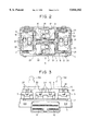
- FIG. 2 is a top view of a printed circuit board, on which module switches indicated in FIG. 1 are mounted, as viewed in the direction indicated by arrow A in FIG. 1;
- FIG. 3 is a side view of the printed circuit board indicated in FIG. 2, as viewed in the direction indicated by arrow C in FIG. 2;
- FIG. 4 is an enlarged cross-sectional view of one of the module switches indicated in FIG. 1;
- FIG. 5 is a perspective view of a mounted power seat switch indicated in FIG. 1;
- FIG. 6 is an electric circuit diagram according to the preferred embodiment of the present invention.
- FIGS. 1 to 6 of the accompanying drawings A preferred embodiment of a power seat switch S according to the present invention will now be described, by way of example, with reference to FIGS. 1 to 6 of the accompanying drawings.
- the power seat switch S includes a terminal block 1 having metal terminals 12 formed therein by, for example, insert molding.
- the terminal block 1 has a connector housing 11 made in one body therewith. End portions of the terminals 12 protrude into the interior of the connector housing 11.
- a printed circuit board 2 having conductive paths 21 made of, for example, copper foil is placed over the terminal block 1.
- Four module switches 3 are mounted on the printed circuit board 2. Each contact of the module switches 3 is connected electrically with each of the terminals 12 through each of the conductive paths 21.
- the module switches 3 each have a similar shape.
- Each of the module switches 3 includes, as shown in FIG. 4, a slider 31 protruding on the upper side thereof, a moving contacting piece 32 which follows the movements of the slider 31, a normally closed contact 33 with which the moving contacting piece 32 is contacted when no external force is applied to the slider 31, a normally open contact 34 with which the moving contacting piece 32 is contacted when an external force is applied to the slider 31, a steel ball 35 for transmitting the external force to the moving contacting piece 32, a first spring 36 for energizing the steel ball 35, and a second spring 37 for energizing the slider 31.
- the module switches 3 are mounted on the printed circuit board 2 with different orientations.
- An inner case 4 is disposed between the module switch 3 and a first moving plate 5, as well as a second moving plate 6, which will be described below.
- the inner case 4 supports the first moving plate 5 and the second moving plate 6.
- the inner case 4 has a knuckle portion 41 for giving a seat knob 8 and a reclining knob 9 of the power seat switch S a knuckle feeling.
- the knuckle portion consists of a recess portion 411, a steel ball 412, and a spring 413.
- the first moving plate 5 and the second moving plate 6 each has a plurality of nails 51 and 61, which are engaged with the sliders 31 of the module switches 3, and a plurality of protrusions 52 and 62, with which the seat knob 8 and the reclining knob 9 are engaged.
- the number of sliders 31 is equal to the number of the nails 51 and 61.
- a case 7 is provided for covering the first moving plate 5 and the second moving plate 6.
- the seat knob 8 is a knob that can be manipulated for regulating a position of a seat portion of a vehicle.
- the seat knob 8 is engaged with the two protrusions 52 extending from the first moving plate 5.
- the reclining knob 9 is a knob that can be manipulated for regulating a reclining posture of the vehicle seat.
- the reclining knob 9 is engaged with the protrusion 62 extending from the second moving plate 6, as well as a protrusion 71 disposed on the upper surface of the case 7.
- the power seat switch S according to the present invention has a structure, which can be mounted by superposing the reclining knob 9 on the terminal block 1, as explained above, and further the module switches 3 are adopted, the power seat switch can be easily mounted and is smaller and cheaper to manufacture.
- FIG. 6 is an electric circuit diagram, in which the power seat switch S is connected with motors M1 to M4, which constitute the actuator section of the power seat system, and a DC power supply B of the vehicle.
- the motor M1 indicated in the circuit diagram moves the seat forward and backward.
- the motor M2 moves the front portion of the seat upward and downward.
- the motor M3 moves the rear portion of the seat upward and downward.
- the motor M4 moves the reclining posture of the seat forward and backward.
- Connection in the power seat switch S indicated in FIG. 6 is made by using movable contacting pieces 321 to 328, normally closed contacts 331 to 338, and normally open contacts 341 to 344.
- the seat knob 8 When it is desired to regulate the seat in forward and backward directions, the seat knob 8 is moved in the directions indicated by arrows X in FIG. 5. Movement of the seat knob 8 in this direction causes the movable contacting piece 321 or 322 indicated in FIG. 6 to be brought into contact with the normally open contact 341, which drives the motor M1 to move the seat forward or backward.
- one side of the seat knob 8 is moved in the directions indicated by arrows Y in FIG. 5. Movement of the seat knob 8 in this manner causes the movable contacting piece 323 or 324 indicated in FIG. 6 to be brought into contact with the normally open contact 342, which drives the motor M2 to move the front portion of the seat forward or backward.
- the reclining knob 9 is pivotally moved in the directions indicated by arrows ⁇ in FIG. 5. Movement of the reclining knob 9 in this manner causes the movable contacting piece 327 or 328 indicated in FIG. 6 to be brought into contact with the normally open contact 344, which drives the motor M4 to move the reclining position forward or backward.
- the power seat switch S can regulate the position of the seat and the reclining posture in a vehicle by manipulating the knobs 8, 9.
- a power seat switch which comprises a terminal block having a connector housing made in one body therewith; a printed circuit board on which a plurality of module switches are mounted; a first moving plate and a second moving plate having a plurality of nails engaged with sliders in the module switches; a case covering the first moving plate and the second moving plate; and a seat knob and a reclining knob engaged with a plurality of protrusions extending from the first moving plate and the second moving plate. Because the seat knob and the reclining knob are superposed together on the switch and the plurality of module switches are used, it is possible to provide a small and cheap power seat switch, which can be easily mounted.
Landscapes
- Engineering & Computer Science (AREA)
- Human Computer Interaction (AREA)
- Aviation & Aerospace Engineering (AREA)
- Transportation (AREA)
- Mechanical Engineering (AREA)
- Switches With Compound Operations (AREA)
- Seats For Vehicles (AREA)
- Slide Switches (AREA)
- Switch Cases, Indication, And Locking (AREA)
Abstract
Description
Claims (18)
Applications Claiming Priority (2)
| Application Number | Priority Date | Filing Date | Title |
|---|---|---|---|
| JP8-071371 | 1996-03-01 | ||
| JP8071371A JPH09240340A (en) | 1996-03-01 | 1996-03-01 | Power seat switch |
Publications (1)
| Publication Number | Publication Date |
|---|---|
| US5844182A true US5844182A (en) | 1998-12-01 |
Family
ID=13458587
Family Applications (1)
| Application Number | Title | Priority Date | Filing Date |
|---|---|---|---|
| US08/810,136 Expired - Fee Related US5844182A (en) | 1996-03-01 | 1997-02-25 | Power seat switch mechanism including actuators for selectively operating switches |
Country Status (2)
| Country | Link |
|---|---|
| US (1) | US5844182A (en) |
| JP (1) | JPH09240340A (en) |
Cited By (29)
| Publication number | Priority date | Publication date | Assignee | Title |
|---|---|---|---|---|
| US6262379B1 (en) | 1999-09-16 | 2001-07-17 | Kabushiki Kaisha Tokai Rika Denki Seisakusho | Switch apparatus |
| US6515241B2 (en) * | 2000-11-09 | 2003-02-04 | Kabushiki Kaisha Tokai Rika Denki Seisakusho | Power seat switch apparatus for vehicle |
| USD471880S1 (en) | 2001-11-13 | 2003-03-18 | Lutron Electronics Co., Inc. | Dimmer switch |
| USD471879S1 (en) | 2001-11-13 | 2003-03-18 | Lutron Electronics Co., Inc. | Dimmer switch |
| USD472221S1 (en) | 2001-11-13 | 2003-03-25 | Lutron Electronics Co., Inc. | Switch |
| USD472526S1 (en) | 2001-11-13 | 2003-04-01 | Lutron Electronics Co., Inc. | Switch |
| USD472527S1 (en) | 2001-11-13 | 2003-04-01 | Lutron Electronics Co. Inc. | Dimmer switch |
| USD477289S1 (en) | 2001-11-13 | 2003-07-15 | Lutron Electronics Co., Inc. | Switch |
| USD477574S1 (en) | 2001-11-13 | 2003-07-22 | Lutron Electronics Co., Inc. | Dimmer switch |
| USD477573S1 (en) | 2001-11-13 | 2003-07-22 | Lutron Electronics Co., Inc. | Dimmer switch |
| USD477572S1 (en) | 2001-11-13 | 2003-07-22 | Lutron Electronics Co., Inc. | Switch |
| USD478554S1 (en) | 2001-11-13 | 2003-08-19 | Lutron Electronics Co., Inc. | Dimmer switch |
| US20040065534A1 (en) * | 2001-11-13 | 2004-04-08 | Noel Mayo | Wallbox dimmer switch having side-by-side pushbutton and dimmer actuators |
| US6765165B1 (en) * | 2003-12-20 | 2004-07-20 | Lear Corporation | Electric switch |
| EP1428717A3 (en) * | 2002-12-13 | 2005-08-31 | Valeo Schalter und Sensoren GmbH | Seat adjusting switch |
| US20060061315A1 (en) * | 2004-09-17 | 2006-03-23 | Schmidt Robert M | Contactless intuitive seat adjuster control |
| US20060070866A1 (en) * | 2004-09-28 | 2006-04-06 | Lear Corporation | Switch cell |
| US20090021041A1 (en) * | 2006-09-09 | 2009-01-22 | Michael Ritzel | Operating unit for at least one adjuster of a vehicle seat |
| US7525052B2 (en) * | 2001-02-02 | 2009-04-28 | Delphi Technologies, Inc. | Multifunction switch assembly for power adjusted vehicle passenger seat |
| DE102008056566A1 (en) * | 2008-11-10 | 2010-05-12 | Rafi Gmbh & Co. Kg | switch |
| US20100258424A1 (en) * | 2009-04-13 | 2010-10-14 | Toyota Boshoku Kabushiki Kaisha | Slide switch structure and power seat switch using the same |
| US20100264006A1 (en) * | 2009-01-21 | 2010-10-21 | Alexandru Salagean | Power seat switch to prevent simultaneous activation |
| CN102237217A (en) * | 2010-04-30 | 2011-11-09 | 安泰汽车电气系统(昆山)有限公司 | Switching module and car seat regulation switch adopting switching module |
| US20160031387A1 (en) * | 2014-08-01 | 2016-02-04 | Dr. Ing. H.C. F. Porsche Aktiengesellschaft | Seat actuating element for a motor vehicle seat |
| DE102017006319A1 (en) * | 2017-07-05 | 2019-01-10 | Leopold Kostal Gmbh & Co. Kg | Operating device for an actuator adjustable motor vehicle seat |
| AU2018206784B2 (en) * | 2013-06-26 | 2020-03-05 | Ricon Corp. | Power transfer seat |
| US11124092B2 (en) | 2013-06-26 | 2021-09-21 | Ricon Corp. | Transfer seat and method |
| US20220083090A1 (en) * | 2019-06-20 | 2022-03-17 | Alps Alpine Co., Ltd. | Operating device |
| US20230108864A1 (en) * | 2020-02-14 | 2023-04-06 | Yanfeng Adient Seating Co., Ltd. | 3D Touch Control-Based Automobile Seat Adjustment Switch |
Families Citing this family (6)
| Publication number | Priority date | Publication date | Assignee | Title |
|---|---|---|---|---|
| JP4560817B2 (en) | 2005-04-28 | 2010-10-13 | 東洋電装株式会社 | Operation switch for vehicle power seat |
| JP2007076398A (en) * | 2005-09-09 | 2007-03-29 | Niles Co Ltd | Power seat switch |
| KR20080015996A (en) * | 2006-08-17 | 2008-02-21 | 한국오므론전장주식회사 | Seat switch structure |
| JP5115037B2 (en) * | 2007-06-05 | 2013-01-09 | マツダ株式会社 | Sheet device |
| KR100981229B1 (en) * | 2008-04-03 | 2010-09-10 | 한국오므론전장주식회사 | Sheet switch using fiber optic |
| CN108447717B (en) * | 2018-05-18 | 2023-12-29 | 广东森下汽车技术有限公司 | Seat lumbar support switch |
Citations (13)
| Publication number | Priority date | Publication date | Assignee | Title |
|---|---|---|---|---|
| US4454390A (en) * | 1978-08-17 | 1984-06-12 | Daimler-Benz Aktiengesellschaft | Switching device for controlling servo drive mechanisms of vehicle seat |
| JPS59103331A (en) * | 1983-09-21 | 1984-06-14 | Hitachi Ltd | Plasma processing apparatus |
| JPS59144841A (en) * | 1982-12-29 | 1984-08-20 | Fujitsu Ltd | Balancing mechanism of cantilever |
| US4473724A (en) * | 1981-08-05 | 1984-09-25 | Kabushiki Kaisha Tokai Rika Denki Seisakusho | Movable element control arrangement |
| US4695682A (en) * | 1985-12-23 | 1987-09-22 | United Technologies Automotive | Seat switch |
| JPH0310443A (en) * | 1989-06-07 | 1991-01-18 | Fujitsu Ltd | Parameter transfer system |
| US5021614A (en) * | 1988-07-25 | 1991-06-04 | Alps Electric Co., Ltd. | Power seat device |
| US5128500A (en) * | 1989-02-17 | 1992-07-07 | Leopold Kostal Gmbh & Co. Kg | Switch assembly |
| US5130501A (en) * | 1989-02-14 | 1992-07-14 | Alps Electric Co., Ltd. | Vehicle seat switch with interlocked actuators |
| US5243156A (en) * | 1991-01-18 | 1993-09-07 | Alps Electric Co., Ltd. | Vehicle power seat multiple switch assembly with selective controller movable in vertical and horizontal directions |
| US5265716A (en) * | 1991-05-10 | 1993-11-30 | Alps Electric Co., Ltd. | Switch with multiple levers and multiple switch assembly using same |
| US5384440A (en) * | 1992-12-17 | 1995-01-24 | United Technologies Automotive, Inc. | Automotive seat switch assembly |
| US5442149A (en) * | 1990-10-17 | 1995-08-15 | Toyo Denso Kabushiki Kaisha | Switch apparatus for automobile |
-
1996
- 1996-03-01 JP JP8071371A patent/JPH09240340A/en active Pending
-
1997
- 1997-02-25 US US08/810,136 patent/US5844182A/en not_active Expired - Fee Related
Patent Citations (14)
| Publication number | Priority date | Publication date | Assignee | Title |
|---|---|---|---|---|
| US4454390A (en) * | 1978-08-17 | 1984-06-12 | Daimler-Benz Aktiengesellschaft | Switching device for controlling servo drive mechanisms of vehicle seat |
| US4454390B1 (en) * | 1978-08-17 | 2000-08-29 | Daimler Benz Ag | Switching device for controlling servo drive mechanisms of vehicle seat |
| US4473724A (en) * | 1981-08-05 | 1984-09-25 | Kabushiki Kaisha Tokai Rika Denki Seisakusho | Movable element control arrangement |
| JPS59144841A (en) * | 1982-12-29 | 1984-08-20 | Fujitsu Ltd | Balancing mechanism of cantilever |
| JPS59103331A (en) * | 1983-09-21 | 1984-06-14 | Hitachi Ltd | Plasma processing apparatus |
| US4695682A (en) * | 1985-12-23 | 1987-09-22 | United Technologies Automotive | Seat switch |
| US5021614A (en) * | 1988-07-25 | 1991-06-04 | Alps Electric Co., Ltd. | Power seat device |
| US5130501A (en) * | 1989-02-14 | 1992-07-14 | Alps Electric Co., Ltd. | Vehicle seat switch with interlocked actuators |
| US5128500A (en) * | 1989-02-17 | 1992-07-07 | Leopold Kostal Gmbh & Co. Kg | Switch assembly |
| JPH0310443A (en) * | 1989-06-07 | 1991-01-18 | Fujitsu Ltd | Parameter transfer system |
| US5442149A (en) * | 1990-10-17 | 1995-08-15 | Toyo Denso Kabushiki Kaisha | Switch apparatus for automobile |
| US5243156A (en) * | 1991-01-18 | 1993-09-07 | Alps Electric Co., Ltd. | Vehicle power seat multiple switch assembly with selective controller movable in vertical and horizontal directions |
| US5265716A (en) * | 1991-05-10 | 1993-11-30 | Alps Electric Co., Ltd. | Switch with multiple levers and multiple switch assembly using same |
| US5384440A (en) * | 1992-12-17 | 1995-01-24 | United Technologies Automotive, Inc. | Automotive seat switch assembly |
Cited By (52)
| Publication number | Priority date | Publication date | Assignee | Title |
|---|---|---|---|---|
| US6262379B1 (en) | 1999-09-16 | 2001-07-17 | Kabushiki Kaisha Tokai Rika Denki Seisakusho | Switch apparatus |
| US6515241B2 (en) * | 2000-11-09 | 2003-02-04 | Kabushiki Kaisha Tokai Rika Denki Seisakusho | Power seat switch apparatus for vehicle |
| US7525052B2 (en) * | 2001-02-02 | 2009-04-28 | Delphi Technologies, Inc. | Multifunction switch assembly for power adjusted vehicle passenger seat |
| USD477578S1 (en) | 2001-11-13 | 2003-07-22 | Lutron Electronics Co., Inc. | Dimmer switch |
| USD477573S1 (en) | 2001-11-13 | 2003-07-22 | Lutron Electronics Co., Inc. | Dimmer switch |
| USD472526S1 (en) | 2001-11-13 | 2003-04-01 | Lutron Electronics Co., Inc. | Switch |
| USD472527S1 (en) | 2001-11-13 | 2003-04-01 | Lutron Electronics Co. Inc. | Dimmer switch |
| USD477290S1 (en) | 2001-11-13 | 2003-07-15 | Lutron Electronics Co., Inc. | Dimmer switch |
| USD477289S1 (en) | 2001-11-13 | 2003-07-15 | Lutron Electronics Co., Inc. | Switch |
| USD477575S1 (en) | 2001-11-13 | 2003-07-22 | Lutron Electronics Co., Inc. | Switch |
| USD477577S1 (en) | 2001-11-13 | 2003-07-22 | Lutron Electronics Co., Inc. | Switch |
| USD477576S1 (en) | 2001-11-13 | 2003-07-22 | Lutron Electronics Co., Inc. | Switch |
| USD471879S1 (en) | 2001-11-13 | 2003-03-18 | Lutron Electronics Co., Inc. | Dimmer switch |
| USD477574S1 (en) | 2001-11-13 | 2003-07-22 | Lutron Electronics Co., Inc. | Dimmer switch |
| USD472221S1 (en) | 2001-11-13 | 2003-03-25 | Lutron Electronics Co., Inc. | Switch |
| USD477572S1 (en) | 2001-11-13 | 2003-07-22 | Lutron Electronics Co., Inc. | Switch |
| USD478054S1 (en) | 2001-11-13 | 2003-08-05 | Lutron Electronics Co., Inc. | Switch |
| USD478554S1 (en) | 2001-11-13 | 2003-08-19 | Lutron Electronics Co., Inc. | Dimmer switch |
| USD479206S1 (en) | 2001-11-13 | 2003-09-02 | Lutron Electronics Co., Inc. | Dimmer switch |
| USD479207S1 (en) | 2001-11-13 | 2003-09-02 | Lutron Electronics Co., Inc. | Dimmer switch |
| USD481365S1 (en) | 2001-11-13 | 2003-10-28 | Lutron Electronics Co., Inc. | Dimmer switch |
| USD482007S1 (en) | 2001-11-13 | 2003-11-11 | Lutron Electronics Co., Inc. | Dimmer switch |
| US20040065534A1 (en) * | 2001-11-13 | 2004-04-08 | Noel Mayo | Wallbox dimmer switch having side-by-side pushbutton and dimmer actuators |
| US6727446B1 (en) | 2001-11-13 | 2004-04-27 | Lutron Electronics Co., Inc. | Wallbox dimmer switch having side-by-side pushbutton and dimmer actuators |
| US6734381B2 (en) | 2001-11-13 | 2004-05-11 | Lutron Electronics Co., Inc. | Wallbox dimmer switch having side-by-side pushbutton and dimmer actuators |
| USD471880S1 (en) | 2001-11-13 | 2003-03-18 | Lutron Electronics Co., Inc. | Dimmer switch |
| EP1428717A3 (en) * | 2002-12-13 | 2005-08-31 | Valeo Schalter und Sensoren GmbH | Seat adjusting switch |
| US6765165B1 (en) * | 2003-12-20 | 2004-07-20 | Lear Corporation | Electric switch |
| GB2418474A (en) * | 2004-09-17 | 2006-03-29 | Lear Corp | Power seat adjustment controller with depressions on inclined areas |
| GB2418474B (en) * | 2004-09-17 | 2007-01-10 | Lear Corp | Contactless intuitive seat adjuster control |
| US7390982B2 (en) | 2004-09-17 | 2008-06-24 | Lear Corporation | Contactless intuitive seat adjuster control |
| US20060061315A1 (en) * | 2004-09-17 | 2006-03-23 | Schmidt Robert M | Contactless intuitive seat adjuster control |
| US20060070866A1 (en) * | 2004-09-28 | 2006-04-06 | Lear Corporation | Switch cell |
| US7078641B2 (en) * | 2004-09-28 | 2006-07-18 | Lear Corporation | Switch Cell |
| US20090021041A1 (en) * | 2006-09-09 | 2009-01-22 | Michael Ritzel | Operating unit for at least one adjuster of a vehicle seat |
| US8143536B2 (en) * | 2008-11-10 | 2012-03-27 | Rafi GmbH & Co., KG | Switch |
| US20100155208A1 (en) * | 2008-11-10 | 2010-06-24 | Theo Beil | Switch |
| DE102008056566A1 (en) * | 2008-11-10 | 2010-05-12 | Rafi Gmbh & Co. Kg | switch |
| US20100264006A1 (en) * | 2009-01-21 | 2010-10-21 | Alexandru Salagean | Power seat switch to prevent simultaneous activation |
| US8835780B2 (en) | 2009-01-21 | 2014-09-16 | Omron Dualtec Automotive Electronics Inc. | Power seat switch to present simultaneous activation |
| US20100258424A1 (en) * | 2009-04-13 | 2010-10-14 | Toyota Boshoku Kabushiki Kaisha | Slide switch structure and power seat switch using the same |
| US8247713B2 (en) * | 2009-04-13 | 2012-08-21 | Toyota Boshoku Kabushiki Kaisha | Slide switch structure and power seat switch using the same |
| CN102237217A (en) * | 2010-04-30 | 2011-11-09 | 安泰汽车电气系统(昆山)有限公司 | Switching module and car seat regulation switch adopting switching module |
| US11124092B2 (en) | 2013-06-26 | 2021-09-21 | Ricon Corp. | Transfer seat and method |
| AU2018206784B2 (en) * | 2013-06-26 | 2020-03-05 | Ricon Corp. | Power transfer seat |
| US9937880B2 (en) * | 2014-08-01 | 2018-04-10 | Dr. Ing. H.C. F. Porsche Aktiengesellschaft | Seat actuating element for a motor vehicle seat |
| US20160031387A1 (en) * | 2014-08-01 | 2016-02-04 | Dr. Ing. H.C. F. Porsche Aktiengesellschaft | Seat actuating element for a motor vehicle seat |
| DE102017006319A1 (en) * | 2017-07-05 | 2019-01-10 | Leopold Kostal Gmbh & Co. Kg | Operating device for an actuator adjustable motor vehicle seat |
| DE102017006319B4 (en) * | 2017-07-05 | 2021-04-01 | Kostal Automobil Elektrik Gmbh & Co. Kg | Operating device for an actuator-adjustable motor vehicle seat |
| US20220083090A1 (en) * | 2019-06-20 | 2022-03-17 | Alps Alpine Co., Ltd. | Operating device |
| US11726518B2 (en) * | 2019-06-20 | 2023-08-15 | Alps Alpine Co., Ltd. | Operating device |
| US20230108864A1 (en) * | 2020-02-14 | 2023-04-06 | Yanfeng Adient Seating Co., Ltd. | 3D Touch Control-Based Automobile Seat Adjustment Switch |
Also Published As
| Publication number | Publication date |
|---|---|
| JPH09240340A (en) | 1997-09-16 |
Similar Documents
| Publication | Publication Date | Title |
|---|---|---|
| US5844182A (en) | Power seat switch mechanism including actuators for selectively operating switches | |
| US4866221A (en) | Remote power mirror switch assembly | |
| US5668357A (en) | Seat combination switch | |
| US4611102A (en) | Switch device for angularly adjusting outer rear mirrors of an automotive vehicle | |
| KR100212107B1 (en) | Lever switches for controlling various electric devices | |
| US5689095A (en) | Switching device | |
| JPH0527930B2 (en) | ||
| US4499342A (en) | Multi-position electric switch | |
| US4476356A (en) | Multi-position electrical switch | |
| CA2182144C (en) | Switch device | |
| JP3228107B2 (en) | Switch device | |
| US7525052B2 (en) | Multifunction switch assembly for power adjusted vehicle passenger seat | |
| EP0269153B1 (en) | Multi-position electrical switch | |
| US5041703A (en) | Mirror control switch for automotive vehicles | |
| JP2755283B2 (en) | Switch device | |
| US5107085A (en) | Clustered push button switches having sheet metal conductors formed with contact tabs | |
| US7528335B2 (en) | Light assembly for vehicle interiors | |
| GB1604432A (en) | Electrical switch combination | |
| JPH062180Y2 (en) | Switch device | |
| JPH0622902Y2 (en) | Dust protection device for power tool switches | |
| JPH0414822Y2 (en) | ||
| KR100521984B1 (en) | Mirror controlling switch in vehicle | |
| JPH10302578A (en) | Vehicular mirror control switch | |
| JPH0113298Y2 (en) | ||
| KR20160138350A (en) | Switch device |
Legal Events
| Date | Code | Title | Description |
|---|---|---|---|
| AS | Assignment |
Owner name: NILES PARTS CO., LTD., JAPAN Free format text: ASSIGNMENT OF ASSIGNORS INTEREST;ASSIGNORS:HIRANO, MINEO;OHTA, HIDETOSHI;TORII, YASUO;REEL/FRAME:008415/0043 Effective date: 19970224 |
|
| FEPP | Fee payment procedure |
Free format text: PAYOR NUMBER ASSIGNED (ORIGINAL EVENT CODE: ASPN); ENTITY STATUS OF PATENT OWNER: LARGE ENTITY |
|
| FPAY | Fee payment |
Year of fee payment: 4 |
|
| FPAY | Fee payment |
Year of fee payment: 8 |
|
| REMI | Maintenance fee reminder mailed | ||
| LAPS | Lapse for failure to pay maintenance fees | ||
| STCH | Information on status: patent discontinuation |
Free format text: PATENT EXPIRED DUE TO NONPAYMENT OF MAINTENANCE FEES UNDER 37 CFR 1.362 |
|
| FP | Lapsed due to failure to pay maintenance fee |
Effective date: 20101201 |