EP1428637A1 - Motorkettensäge mit Griff - Google Patents
Motorkettensäge mit Griff Download PDFInfo
- Publication number
- EP1428637A1 EP1428637A1 EP03024278A EP03024278A EP1428637A1 EP 1428637 A1 EP1428637 A1 EP 1428637A1 EP 03024278 A EP03024278 A EP 03024278A EP 03024278 A EP03024278 A EP 03024278A EP 1428637 A1 EP1428637 A1 EP 1428637A1
- Authority
- EP
- European Patent Office
- Prior art keywords
- handle
- shell
- hand
- implement according
- held implement
- Prior art date
- Legal status (The legal status is an assumption and is not a legal conclusion. Google has not performed a legal analysis and makes no representation as to the accuracy of the status listed.)
- Granted
Links
- 238000002347 injection Methods 0.000 claims description 8
- 239000007924 injection Substances 0.000 claims description 8
- 230000002787 reinforcement Effects 0.000 claims description 3
- 239000002828 fuel tank Substances 0.000 claims 1
- 238000004519 manufacturing process Methods 0.000 description 3
- 241000237983 Trochidae Species 0.000 description 2
- 230000037396 body weight Effects 0.000 description 1
- 230000001427 coherent effect Effects 0.000 description 1
- 238000009434 installation Methods 0.000 description 1
- 210000001331 nose Anatomy 0.000 description 1
- 230000003014 reinforcing effect Effects 0.000 description 1
- 238000003466 welding Methods 0.000 description 1
Images


Classifications
-
- B—PERFORMING OPERATIONS; TRANSPORTING
- B27—WORKING OR PRESERVING WOOD OR SIMILAR MATERIAL; NAILING OR STAPLING MACHINES IN GENERAL
- B27B—SAWS FOR WOOD OR SIMILAR MATERIAL; COMPONENTS OR ACCESSORIES THEREFOR
- B27B17/00—Chain saws; Equipment therefor
- B27B17/0008—Means for carrying the chain saw, e.g. handles
Definitions
- the invention relates to a hand-held implement with a handle.
- Hand-held tools with handles for example motor chainsaws are well known.
- the object of the invention is to provide a hand-held implement with a handle To provide that is inexpensive to manufacture and still a smooth Has outer skin.
- the task is carried out by a generic tool with a handle a handle section on the user side and a bottom side of the Handle section arranged tread area and a detachable one-piece Upper handle shell, the handle section on the user side and the tread area at least essentially covers the bottom, solved.
- the handle section is covered on the user side by the upper shell. This is a switching mechanism that may be built into it protected and at the same time easy to service.
- the upper shell is an inexpensive one-piece injection molded part educated. You can functional elements such as eyelets, hooks. ⁇ . Have.
- a cheap to produce variant of the hand-held implement has a larger tank half shell to which a smaller tank half shell is attached Training of the tank is welded. The weld seam then runs alongside the handle. The inside of the handle is injection molded in one piece.
- the handle which is open on the user side, is complete thanks to the top handle coverable.
- the entire handle is smooth and visually appealing as also cheap to manufacture.
- the step area has an in for easy installation of the top handle Device longitudinal dovetail guide on and the Upper handle shell has wrappings arranged on the outside, with which the Handle top shell can be pushed in the direction from the user to the device.
- the upper handle shell can be in the tread area first and / or in the handle section have second fastening means.
- Screw domes can be used in the Step area may be provided, which if necessary for fastening the Handle top shell serve.
- One screw can be inserted into the Grip tops provided breakthrough areas are pushed in and the associated screw domes are tightened.
- the grip section of the top grip shell is preferably semi-tubular formed and has two at an angle to the housing end
- Direction of action of the screw arranged lugs around the top handle by tightening a hole located through a user side pull the guided screw onto the handle contour.
- the noses are in for it a suitable angle to the direction of action of the screw.
- the inside wall of the handle can be a recess for a throttle and the The top handle shell can have a recess for a lock button.
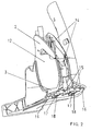
- FIG. 1 shows the tank handle unit as a component of a motor chain saw Chain saw is not shown. It is made up of several components composed. The invention is due to the tank handle unit most vividly writable.
- the tank-handle unit has the handle 1 in the area facing the user.
- the handle 1 has a user-facing handle section 2 and one o Floor area 3.
- the chain saw shows one through Pull rope ignitable two-stroke engine. During the quick tightening of the The user can pull the rope with his body weight onto the tread area 3 kick and fix the chain saw to the floor in this way.
- a large tank shell 4 with a receptacle 5 for a bow handle and the handle inner wall 12 are injection molded in one piece.
- the handle 1 has no weld seams along its circumference.
- On the open Tank 6 of the large tank shell 4 is a small tank shell (not shown) weldable.
- the weld seam 7 runs completely alongside the handle 1 and the receptacle 5 for the bow handle opposite.
- the handle 1 is on the floor and user side by a one-piece injection molded Top handle 8 covered.
- the upper grip shell 8 has in the grip section 2 a recess 9 for a lock button and two in the step area 3 Cutouts 10 for snap hooks.
- the Upper shell 8 two at a suitable angle to the direction of action Screw on extending lugs 11.
- the lugs 11 act with one Screw which is guided through a bore 20 according to FIG. 2 in the handle section is together.
- a handle inner wall 12 runs perpendicular to the Chainsaw longitudinally arranged handle opening 13. Die Handle inner wall 12 is injection molded in one piece.
- FIG. 2 shows the tank handle unit according to Figure 1 with the removed Upper handle shell 8.
- the handle section 2 of the inner handle wall 12 is in the essentially semi-tubular and in the longitudinal direction bent on the implement side.
- the bottom side of the tread area 3 also has a reinforcement profile 15 on.
- the reinforcement profile 15 is on both sides of one Dovetail guide 16 limited.
- the dovetail guide 16 is a bent edge of the tread area 3.
- the Dovetail guide 16 acts with grips in the tread area 3 Upper shell 8 together.
- two snap hooks 17 are arranged on the bottom side with the two recesses 10 in the tread area of the top handle 8 interact.
- one Dome 18 provided in addition to the two snap hooks 17 .
- additional breakthrough areas 21 on the top handle 8 with a Screw are broken and in the associated screw domes 18 are tightened.
- the top handle 8 closes Completely from the foot area 3 on the floor and protect it against Dirt entry.
- FIG. 3 shows the removed upper handle shell 8.
- the upper handle shell is injection molded in one piece. In the tread area there are two wraps on the long side intended.
- the handle section has two lugs at its outer end on with a screw passed through the upper bore 20 interact and the upper shell 8 in the grip area 2 closely to the handle 1 pull.
Landscapes
- Life Sciences & Earth Sciences (AREA)
- Engineering & Computer Science (AREA)
- Mechanical Engineering (AREA)
- Wood Science & Technology (AREA)
- Forests & Forestry (AREA)
- Details Of Rigid Or Semi-Rigid Containers (AREA)
- Food-Manufacturing Devices (AREA)
- Injection Moulding Of Plastics Or The Like (AREA)
- Catching Or Destruction (AREA)
Abstract
Description
- Figur 1
- Eine perspektivische Ansicht einer Tank-Griff-Einheit für ein erfindungsgemäßes handgeführtes Arbeitsgerät,
- Figur 2
- eine Tank-Griff-Einheit gemäß Figur 1 mit abgenommener Griffoberschale und
- Figur 3
- erfindungsgemäße Griffoberschale.
Claims (11)
- Handgeführtes Arbeitsgerät mit Griff (1) mit einem benutzerseitigen Griffabschnitt (2) und einem bodenseitig des Griffabschnitts (2) angeordneten Trittbereich (3) und einer lösbaren einstückigen Griffoberschale (8), die den Griffabschnitt (2) benutzerseitig und den Trittbereich (3) bodenseitig wenigstens im wesentlichen abdeckt.
- Handgeführtes Arbeitsgerät nach Anspruch 1, dadurch gekennzeichnet, daß der Trittbereich (3) ein bodenseitiges Verstärkungsprofil (15) aufweist.
- Handgeführtes Arbeitsgerät nach Anspruch 1 oder 2 gekennzeichnet durch eine einteilig spritzgegossene eine Grifföffnung (13) umlaufende Griffinnenwandung (12).
- Handgeführtes Arbeitgerät nach Anspruch 3, dadurch gekennzeichnet, daß die Griffoberschale (8) am benutzerseitigen Ende ein Funktionselement, insbesondere eine Öse, aufweist.
- Handgeführtes Arbeitsgerät nach den Ansprüchen 1, 2, 3 oder 4, dadurch gekennzeichnet, daß die Griffinnenwandung (12) und eine große Tankhalbschale (4) einstückig spritzgegossen sind und eine kleine Tankhalbschale zur Ausbildung eines Kraftstofftankes (6) mit der großen Tankhalbschale (4) entlang einer neben dem Griff (1) verlaufenden Naht (7) verschweißt ist.
- Handgeführtes Arbeitsgerät nach einem oder mehreren der vorgenannten Ansprüche, dadurch gekennzeichnet, daß der Trittbereich (3) eine in Gerätelängsrichtung verlaufende Schwalbenschwanzführung (16) aufweist und die Griffoberschale (8) außenseitig angeordnete Umgriffe (19) aufweist mit denen die Griffoberschale (8) in Richtung vom Benutzer zum Gerät hin aufschiebbar ist.
- Handgeführtes Arbeitsgerät nach einem oder mehreren der vorgenannten Ansprüche, dadurch gekennzeichnet, daß die Griffoberschale (8) im Trittbereich (3) erste Befestigungsmittel und/oder im Griffabschnitt zweite Befestigungsmittel aufweist.
- Handgeführtes Arbeitsgerät nach Anspruch 7, dadurch gekennzeichnet, daß die ersten Befestigungsmittel Aussparungen (10) aufweisen, um mit am Trittbereich (3) bodenseitig abstehenden Schnapphaken (17) eine Schnappverbindung auszubilden.
- Handgeführtes Arbeitsgerät nach Anspruch 7 oder 8, dadurch gekennzeichnet, daß der Trittbereich (3) bodenseitig abstehende Schraubendome (18) und die ersten Befestigungsmittel in der Griffoberschale zugeordnete Durchbruchbereiche für in die Schraubendome (18) zur Fixierung der Griffoberschale (8) schraubbare Schrauben aufweisen.
- Handgeführtes Arbeitsgerät nach Anspruch 7, dadurch gekennzeichnet, daß die zweiten Befestigungsmittel eine benutzerseitig angeordnete Bohrung (20) für eine Schraube und zwei am geräteseitigen Ende unter einem Winkel zur Wirkrichtung der Schraube angeordnete Nasen (11) aufweisen.
- Handgeführtes Arbeitsgerät nach einem oder mehreren der vorgenannten Ansprüche, dadurch gekennzeichnet, daß der Griffabschnitt (2) zur Aufnahme einer Schaltmechanik hohl ausgebildet ist und die Griffinnenwandung (12) eine Aussparung für einen Gashebel und die Griffoberschale (8) eine Aussparung (9) für eine Sperrtaste aufweist.
Applications Claiming Priority (2)
| Application Number | Priority Date | Filing Date | Title |
|---|---|---|---|
| DE20219246U DE20219246U1 (de) | 2002-12-12 | 2002-12-12 | Handgeführtes Arbeitsgerät mit Griff |
| DE20219246U | 2002-12-12 |
Publications (2)
| Publication Number | Publication Date |
|---|---|
| EP1428637A1 true EP1428637A1 (de) | 2004-06-16 |
| EP1428637B1 EP1428637B1 (de) | 2005-09-21 |
Family
ID=7977895
Family Applications (1)
| Application Number | Title | Priority Date | Filing Date |
|---|---|---|---|
| EP03024278A Expired - Lifetime EP1428637B1 (de) | 2002-12-12 | 2003-10-23 | Handgeführtes Arbeitsgerät wie eine Motorkettensäge mit Griff |
Country Status (4)
| Country | Link |
|---|---|
| US (1) | US7204025B2 (de) |
| EP (1) | EP1428637B1 (de) |
| AT (1) | ATE304925T1 (de) |
| DE (2) | DE20219246U1 (de) |
Families Citing this family (14)
| Publication number | Priority date | Publication date | Assignee | Title |
|---|---|---|---|---|
| DE20314982U1 (de) | 2003-09-26 | 2003-11-13 | Dolmar GmbH, 22045 Hamburg | Griff für einen Seilzugstarter einer Motorkettensäge |
| DE202004007699U1 (de) * | 2004-05-13 | 2004-07-15 | Dolmar Gmbh | Fußeinheit für Trennschleifer |
| TW200704183A (en) | 2005-01-27 | 2007-01-16 | Matrix Tv | Dynamic mosaic extended electronic programming guide for television program selection and display |
| US8875196B2 (en) | 2005-08-13 | 2014-10-28 | Webtuner Corp. | System for network and local content access |
| JP5091399B2 (ja) * | 2005-11-15 | 2012-12-05 | ハスクバーナ・ゼノア株式会社 | チェーンソウ |
| JP2007177774A (ja) * | 2005-12-28 | 2007-07-12 | Komatsu Zenoah Co | 2サイクルエンジン |
| JP2007176128A (ja) * | 2005-12-28 | 2007-07-12 | Komatsu Zenoah Co | チェーンソー |
| US20090145271A1 (en) * | 2006-06-26 | 2009-06-11 | Par Martinsson | Handle member |
| US20080092976A1 (en) * | 2006-10-20 | 2008-04-24 | Komatsu Zenoah Co. | Blower duct |
| US20090038106A1 (en) * | 2007-08-10 | 2009-02-12 | Zenoah Co., Ltd. | Engine blower |
| DE102008062156A1 (de) * | 2008-12-13 | 2010-06-17 | Gardena Manufacturing Gmbh | Handgriffanordnung, Verfahren zur Herstellung einer solchen Handgriffanordnung und Gerätesystem mit solchen Handgriffanordnungen |
| CN102574291B (zh) * | 2009-10-23 | 2015-09-23 | 胡斯华纳有限公司 | 用于电动手持工具的把手部件 |
| CA2837198A1 (en) | 2011-05-24 | 2012-11-29 | Webtuner Corp. | System and method to increase efficiency and speed of analytics report generation in audience measurement systems |
| AU2012258513A1 (en) | 2011-05-26 | 2013-12-12 | WebTuner, Corporation | Highly scalable audience measurement system with client event pre-processing |
Citations (2)
| Publication number | Priority date | Publication date | Assignee | Title |
|---|---|---|---|---|
| US4654970A (en) * | 1983-08-26 | 1987-04-07 | Kioritz Corporation | Heated handle for a chain saw |
| DE10104866A1 (de) * | 2001-02-03 | 2002-08-14 | Bosch Gmbh Robert | Handwerkzeugmaschine mit einem elektrische Komponenten aufnehmenden Handgriff |
Family Cites Families (19)
| Publication number | Priority date | Publication date | Assignee | Title |
|---|---|---|---|---|
| US3844360A (en) * | 1972-12-18 | 1974-10-29 | Textron Inc | Hand held power tool with duplex handle |
| US4141143A (en) * | 1977-10-26 | 1979-02-27 | Mcculloch Corporation | Chain saw handle and vibration isolation system |
| JPS56139761A (en) * | 1980-03-31 | 1981-10-31 | Shimadzu Corp | Sealing arm device for operation |
| DE3525593A1 (de) * | 1985-07-18 | 1987-01-22 | Stihl Maschf Andreas | Motorkettensaege |
| US4660721A (en) * | 1986-04-07 | 1987-04-28 | Cvp Systems, Inc. | Sterilization package |
| EP0267973B1 (de) * | 1986-11-11 | 1992-02-12 | Black & Decker Inc. | Kraftgetriebene Säge, insbesondere elektromotorisch angetriebene Säge |
| JP3029622B2 (ja) * | 1988-04-08 | 2000-04-04 | アンドレアス シュティール | 可搬式パワーチェーンソーの湾曲グリップ |
| US4874090A (en) * | 1988-10-24 | 1989-10-17 | American Sterilizer Company | Self-seal sterilization pouch |
| US4912848A (en) * | 1989-01-09 | 1990-04-03 | Textron, Inc. | Power tool handle |
| US5101567A (en) * | 1991-06-27 | 1992-04-07 | Cool James E | Chain saw electric all-stop safety switch |
| US5222600A (en) * | 1992-07-28 | 1993-06-29 | Stoddard James T | Autoclave pouch |
| US5960549A (en) * | 1993-06-30 | 1999-10-05 | Andreas Stihl Ag & Co. | Plastic handle member for manually guided power chain saws |
| DE19522218B4 (de) * | 1994-06-23 | 2010-11-11 | Fa. Andreas Stihl | Griffanordnung für eine Motorkettensäge |
| US5551157A (en) * | 1995-05-17 | 1996-09-03 | Wu; Chin-Sung | Tool handle assembly for garden tools |
| US5738064A (en) * | 1995-11-15 | 1998-04-14 | Wci Outdoor Products, Inc. | Vibration weld chassis assembly |
| JP3822333B2 (ja) * | 1997-05-14 | 2006-09-20 | 株式会社共立 | 動力作業機用ハンドル装置 |
| US6502311B1 (en) * | 1999-08-14 | 2003-01-07 | The Olympia Group, Inc. | Adjustable safety utility knife with slip resistant elements |
| JP4071413B2 (ja) * | 2000-01-27 | 2008-04-02 | 株式会社共立 | 携帯型動力作業機 |
| DE20209522U1 (de) | 2002-06-19 | 2002-08-29 | Dolmar GmbH, 22045 Hamburg | Werkzeug mit beheizbarem Griff |
-
2002
- 2002-12-12 DE DE20219246U patent/DE20219246U1/de not_active Expired - Lifetime
-
2003
- 2003-10-23 DE DE50301220T patent/DE50301220D1/de not_active Expired - Lifetime
- 2003-10-23 AT AT03024278T patent/ATE304925T1/de not_active IP Right Cessation
- 2003-10-23 EP EP03024278A patent/EP1428637B1/de not_active Expired - Lifetime
- 2003-12-11 US US10/733,512 patent/US7204025B2/en not_active Expired - Fee Related
Patent Citations (2)
| Publication number | Priority date | Publication date | Assignee | Title |
|---|---|---|---|---|
| US4654970A (en) * | 1983-08-26 | 1987-04-07 | Kioritz Corporation | Heated handle for a chain saw |
| DE10104866A1 (de) * | 2001-02-03 | 2002-08-14 | Bosch Gmbh Robert | Handwerkzeugmaschine mit einem elektrische Komponenten aufnehmenden Handgriff |
Also Published As
| Publication number | Publication date |
|---|---|
| DE20219246U1 (de) | 2003-02-20 |
| EP1428637B1 (de) | 2005-09-21 |
| ATE304925T1 (de) | 2005-10-15 |
| US7204025B2 (en) | 2007-04-17 |
| US20040172834A1 (en) | 2004-09-09 |
| DE50301220D1 (de) | 2006-02-02 |
Similar Documents
| Publication | Publication Date | Title |
|---|---|---|
| EP1428637B1 (de) | Handgeführtes Arbeitsgerät wie eine Motorkettensäge mit Griff | |
| DE19925281B4 (de) | Handgeführtes Arbeitsgerät, insbesondere Heckenschere mit vibrationsgedämpften Handgriffen | |
| DE10260466B4 (de) | Handgeführtes Arbeitsgerät | |
| US5010746A (en) | Bicycle lock | |
| DE3431080C2 (de) | ||
| DE19631033B4 (de) | Tragbares, handgeführtes Arbeitsgerät mit einem hinteren Handgriff | |
| DE102006004776B4 (de) | Handgeführtes, tragbares Saug-/Blasgerät | |
| DE4120876C2 (de) | Arbeitsgerät, insbesondere Motorkettensäge | |
| EP0750836B1 (de) | Heckenschere | |
| DE4100959A1 (de) | Geraetekasten | |
| DE102008064007A1 (de) | Heckenschere | |
| DE3916414C2 (de) | ||
| DE9213272U1 (de) | Arbeitsgerät, insbesondere Motorkettensäge | |
| DE102013012513A1 (de) | "Handgeführtes Arbeitsgerät" | |
| DE102008063995B4 (de) | Heckenschere | |
| US6820341B2 (en) | Hacksaw having improved blade storage | |
| DE3525593A1 (de) | Motorkettensaege | |
| DE102015016485A1 (de) | Handgeführtes Arbeitsgerät mit einer Steuereinrichtung | |
| DE102005036885B4 (de) | Handgeführtes Arbeitsgerät | |
| DE102005047882B4 (de) | Handgeführtes Arbeitsgerät | |
| DE19955930B4 (de) | Handbohrmaschine mit einem Verbrennungsmotor | |
| DE102006003202B4 (de) | Arbeitsgerät | |
| EP3744968A1 (de) | Federgehäuse und anwerfvorrichtung mit einem federgehäuse | |
| DE19631031A1 (de) | Motorkettensäge | |
| DE102005063615B3 (de) | Handgeführtes Arbeitsgerät |
Legal Events
| Date | Code | Title | Description |
|---|---|---|---|
| PUAI | Public reference made under article 153(3) epc to a published international application that has entered the european phase |
Free format text: ORIGINAL CODE: 0009012 |
|
| 17P | Request for examination filed |
Effective date: 20031204 |
|
| AK | Designated contracting states |
Kind code of ref document: A1 Designated state(s): AT BE BG CH CY CZ DE DK EE ES FI FR GB GR HU IE IT LI LU MC NL PT RO SE SI SK TR |
|
| AX | Request for extension of the european patent |
Extension state: AL LT LV MK |
|
| 17Q | First examination report despatched |
Effective date: 20041029 |
|
| AKX | Designation fees paid |
Designated state(s): AT BE BG CH CY CZ DE DK EE ES FI FR GB GR HU IE IT LI LU MC NL PT RO SE SI SK TR |
|
| GRAP | Despatch of communication of intention to grant a patent |
Free format text: ORIGINAL CODE: EPIDOSNIGR1 |
|
| RTI1 | Title (correction) |
Free format text: HAND GUIDED TOOL AS A POWER CHAIN SAW WITH HANDLE |
|
| GRAS | Grant fee paid |
Free format text: ORIGINAL CODE: EPIDOSNIGR3 |
|
| GRAA | (expected) grant |
Free format text: ORIGINAL CODE: 0009210 |
|
| AK | Designated contracting states |
Kind code of ref document: B1 Designated state(s): AT BE BG CH CY CZ DE DK EE ES FI FR GB GR HU IE IT LI LU MC NL PT RO SE SI SK TR |
|
| PG25 | Lapsed in a contracting state [announced via postgrant information from national office to epo] |
Ref country code: SI Free format text: LAPSE BECAUSE OF FAILURE TO SUBMIT A TRANSLATION OF THE DESCRIPTION OR TO PAY THE FEE WITHIN THE PRESCRIBED TIME-LIMIT Effective date: 20050921 Ref country code: CZ Free format text: LAPSE BECAUSE OF FAILURE TO SUBMIT A TRANSLATION OF THE DESCRIPTION OR TO PAY THE FEE WITHIN THE PRESCRIBED TIME-LIMIT Effective date: 20050921 Ref country code: GB Free format text: LAPSE BECAUSE OF FAILURE TO SUBMIT A TRANSLATION OF THE DESCRIPTION OR TO PAY THE FEE WITHIN THE PRESCRIBED TIME-LIMIT Effective date: 20050921 Ref country code: NL Free format text: LAPSE BECAUSE OF FAILURE TO SUBMIT A TRANSLATION OF THE DESCRIPTION OR TO PAY THE FEE WITHIN THE PRESCRIBED TIME-LIMIT Effective date: 20050921 Ref country code: FI Free format text: LAPSE BECAUSE OF FAILURE TO SUBMIT A TRANSLATION OF THE DESCRIPTION OR TO PAY THE FEE WITHIN THE PRESCRIBED TIME-LIMIT Effective date: 20050921 Ref country code: SK Free format text: LAPSE BECAUSE OF FAILURE TO SUBMIT A TRANSLATION OF THE DESCRIPTION OR TO PAY THE FEE WITHIN THE PRESCRIBED TIME-LIMIT Effective date: 20050921 Ref country code: EE Free format text: LAPSE BECAUSE OF FAILURE TO SUBMIT A TRANSLATION OF THE DESCRIPTION OR TO PAY THE FEE WITHIN THE PRESCRIBED TIME-LIMIT Effective date: 20050921 Ref country code: RO Free format text: LAPSE BECAUSE OF FAILURE TO SUBMIT A TRANSLATION OF THE DESCRIPTION OR TO PAY THE FEE WITHIN THE PRESCRIBED TIME-LIMIT Effective date: 20050921 Ref country code: TR Free format text: LAPSE BECAUSE OF FAILURE TO SUBMIT A TRANSLATION OF THE DESCRIPTION OR TO PAY THE FEE WITHIN THE PRESCRIBED TIME-LIMIT Effective date: 20050921 Ref country code: IE Free format text: LAPSE BECAUSE OF FAILURE TO SUBMIT A TRANSLATION OF THE DESCRIPTION OR TO PAY THE FEE WITHIN THE PRESCRIBED TIME-LIMIT Effective date: 20050921 |
|
| REG | Reference to a national code |
Ref country code: GB Ref legal event code: FG4D Free format text: NOT ENGLISH |
|
| REG | Reference to a national code |
Ref country code: CH Ref legal event code: EP |
|
| REG | Reference to a national code |
Ref country code: IE Ref legal event code: FG4D Free format text: LANGUAGE OF EP DOCUMENT: GERMAN |
|
| PG25 | Lapsed in a contracting state [announced via postgrant information from national office to epo] |
Ref country code: AT Free format text: LAPSE BECAUSE OF NON-PAYMENT OF DUE FEES Effective date: 20051023 Ref country code: CY Free format text: LAPSE BECAUSE OF FAILURE TO SUBMIT A TRANSLATION OF THE DESCRIPTION OR TO PAY THE FEE WITHIN THE PRESCRIBED TIME-LIMIT Effective date: 20051023 |
|
| REF | Corresponds to: |
Ref document number: 50301220 Country of ref document: DE Date of ref document: 20051027 Kind code of ref document: P |
|
| PG25 | Lapsed in a contracting state [announced via postgrant information from national office to epo] |
Ref country code: MC Free format text: LAPSE BECAUSE OF NON-PAYMENT OF DUE FEES Effective date: 20051031 Ref country code: BE Free format text: LAPSE BECAUSE OF NON-PAYMENT OF DUE FEES Effective date: 20051031 |
|
| PG25 | Lapsed in a contracting state [announced via postgrant information from national office to epo] |
Ref country code: LU Free format text: LAPSE BECAUSE OF NON-PAYMENT OF DUE FEES Effective date: 20051121 |
|
| PG25 | Lapsed in a contracting state [announced via postgrant information from national office to epo] |
Ref country code: GR Free format text: LAPSE BECAUSE OF FAILURE TO SUBMIT A TRANSLATION OF THE DESCRIPTION OR TO PAY THE FEE WITHIN THE PRESCRIBED TIME-LIMIT Effective date: 20051221 Ref country code: DK Free format text: LAPSE BECAUSE OF FAILURE TO SUBMIT A TRANSLATION OF THE DESCRIPTION OR TO PAY THE FEE WITHIN THE PRESCRIBED TIME-LIMIT Effective date: 20051221 Ref country code: BG Free format text: LAPSE BECAUSE OF FAILURE TO SUBMIT A TRANSLATION OF THE DESCRIPTION OR TO PAY THE FEE WITHIN THE PRESCRIBED TIME-LIMIT Effective date: 20051221 |
|
| REG | Reference to a national code |
Ref country code: SE Ref legal event code: TRGR |
|
| PG25 | Lapsed in a contracting state [announced via postgrant information from national office to epo] |
Ref country code: ES Free format text: LAPSE BECAUSE OF FAILURE TO SUBMIT A TRANSLATION OF THE DESCRIPTION OR TO PAY THE FEE WITHIN THE PRESCRIBED TIME-LIMIT Effective date: 20060101 |
|
| REF | Corresponds to: |
Ref document number: 50301220 Country of ref document: DE Date of ref document: 20060202 Kind code of ref document: P |
|
| PG25 | Lapsed in a contracting state [announced via postgrant information from national office to epo] |
Ref country code: PT Free format text: LAPSE BECAUSE OF FAILURE TO SUBMIT A TRANSLATION OF THE DESCRIPTION OR TO PAY THE FEE WITHIN THE PRESCRIBED TIME-LIMIT Effective date: 20060221 |
|
| NLV1 | Nl: lapsed or annulled due to failure to fulfill the requirements of art. 29p and 29m of the patents act | ||
| PG25 | Lapsed in a contracting state [announced via postgrant information from national office to epo] |
Ref country code: HU Free format text: LAPSE BECAUSE OF FAILURE TO SUBMIT A TRANSLATION OF THE DESCRIPTION OR TO PAY THE FEE WITHIN THE PRESCRIBED TIME-LIMIT Effective date: 20060322 |
|
| GBV | Gb: ep patent (uk) treated as always having been void in accordance with gb section 77(7)/1977 [no translation filed] |
Effective date: 20050921 |
|
| REG | Reference to a national code |
Ref country code: IE Ref legal event code: FD4D |
|
| ET | Fr: translation filed | ||
| PLBE | No opposition filed within time limit |
Free format text: ORIGINAL CODE: 0009261 |
|
| STAA | Information on the status of an ep patent application or granted ep patent |
Free format text: STATUS: NO OPPOSITION FILED WITHIN TIME LIMIT |
|
| 26N | No opposition filed |
Effective date: 20060622 |
|
| PGFP | Annual fee paid to national office [announced via postgrant information from national office to epo] |
Ref country code: SE Payment date: 20061009 Year of fee payment: 4 |
|
| PGFP | Annual fee paid to national office [announced via postgrant information from national office to epo] |
Ref country code: IT Payment date: 20061031 Year of fee payment: 4 |
|
| BERE | Be: lapsed |
Owner name: DOLMAR G.M.B.H. Effective date: 20051031 |
|
| EUG | Se: european patent has lapsed | ||
| REG | Reference to a national code |
Ref country code: CH Ref legal event code: PL |
|
| PG25 | Lapsed in a contracting state [announced via postgrant information from national office to epo] |
Ref country code: CH Free format text: LAPSE BECAUSE OF NON-PAYMENT OF DUE FEES Effective date: 20071031 Ref country code: LI Free format text: LAPSE BECAUSE OF NON-PAYMENT OF DUE FEES Effective date: 20071031 |
|
| REG | Reference to a national code |
Ref country code: FR Ref legal event code: ST Effective date: 20080630 |
|
| PG25 | Lapsed in a contracting state [announced via postgrant information from national office to epo] |
Ref country code: SE Free format text: LAPSE BECAUSE OF NON-PAYMENT OF DUE FEES Effective date: 20071024 |
|
| PG25 | Lapsed in a contracting state [announced via postgrant information from national office to epo] |
Ref country code: FR Free format text: LAPSE BECAUSE OF NON-PAYMENT OF DUE FEES Effective date: 20071031 |
|
| PGFP | Annual fee paid to national office [announced via postgrant information from national office to epo] |
Ref country code: FR Payment date: 20061031 Year of fee payment: 4 |
|
| PG25 | Lapsed in a contracting state [announced via postgrant information from national office to epo] |
Ref country code: IT Free format text: LAPSE BECAUSE OF NON-PAYMENT OF DUE FEES Effective date: 20071023 |
|
| PGFP | Annual fee paid to national office [announced via postgrant information from national office to epo] |
Ref country code: DE Payment date: 20161221 Year of fee payment: 14 |
|
| REG | Reference to a national code |
Ref country code: DE Ref legal event code: R119 Ref document number: 50301220 Country of ref document: DE |
|
| PG25 | Lapsed in a contracting state [announced via postgrant information from national office to epo] |
Ref country code: DE Free format text: LAPSE BECAUSE OF NON-PAYMENT OF DUE FEES Effective date: 20180501 |