EP1427652B1 - Doppelflasche für die gleichmässige abgabe zweier flüssigkeiten - Google Patents
Doppelflasche für die gleichmässige abgabe zweier flüssigkeiten Download PDFInfo
- Publication number
- EP1427652B1 EP1427652B1 EP03785106A EP03785106A EP1427652B1 EP 1427652 B1 EP1427652 B1 EP 1427652B1 EP 03785106 A EP03785106 A EP 03785106A EP 03785106 A EP03785106 A EP 03785106A EP 1427652 B1 EP1427652 B1 EP 1427652B1
- Authority
- EP
- European Patent Office
- Prior art keywords
- chamber
- bottle
- wall
- exit opening
- liquid
- Prior art date
- Legal status (The legal status is an assumption and is not a legal conclusion. Google has not performed a legal analysis and makes no representation as to the accuracy of the status listed.)
- Expired - Lifetime
Links
Images


Classifications
-
- B—PERFORMING OPERATIONS; TRANSPORTING
- B65—CONVEYING; PACKING; STORING; HANDLING THIN OR FILAMENTARY MATERIAL
- B65D—CONTAINERS FOR STORAGE OR TRANSPORT OF ARTICLES OR MATERIALS, e.g. BAGS, BARRELS, BOTTLES, BOXES, CANS, CARTONS, CRATES, DRUMS, JARS, TANKS, HOPPERS, FORWARDING CONTAINERS; ACCESSORIES, CLOSURES, OR FITTINGS THEREFOR; PACKAGING ELEMENTS; PACKAGES
- B65D81/00—Containers, packaging elements, or packages, for contents presenting particular transport or storage problems, or adapted to be used for non-packaging purposes after removal of contents
- B65D81/32—Containers, packaging elements, or packages, for contents presenting particular transport or storage problems, or adapted to be used for non-packaging purposes after removal of contents for packaging two or more different materials which must be maintained separate prior to use in admixture
- B65D81/3283—Cylindrical or polygonal containers, e.g. bottles, with two or more substantially axially offset, side-by-side compartments for simultaneous dispensing
- B65D81/3288—Cylindrical or polygonal containers, e.g. bottles, with two or more substantially axially offset, side-by-side compartments for simultaneous dispensing composed of two or more separate containers joined to each other
-
- C—CHEMISTRY; METALLURGY
- C11—ANIMAL OR VEGETABLE OILS, FATS, FATTY SUBSTANCES OR WAXES; FATTY ACIDS THEREFROM; DETERGENTS; CANDLES
- C11D—DETERGENT COMPOSITIONS; USE OF SINGLE SUBSTANCES AS DETERGENTS; SOAP OR SOAP-MAKING; RESIN SOAPS; RECOVERY OF GLYCEROL
- C11D17/00—Detergent materials or soaps characterised by their shape or physical properties
- C11D17/04—Detergent materials or soaps characterised by their shape or physical properties combined with or containing other objects
- C11D17/041—Compositions releasably affixed on a substrate or incorporated into a dispensing means
Definitions
- This invention relates to a liquid two part cleaning composition and a bottle for dispensing the liquid two part cleaning composition.
- Two part cleaning systems are available in which an acidic component and a basic component are kept physically separated until use and are mixed upon use to create a foaming or effervescent cleaning mixture.
- PCT Intemational Application WO 01/00765 describes an aqueous liquid detergent composition that is prepared and delivered from a dual-compartment container.
- the first compartment may contain a basic effervescent agent (e.g., sodium bicarbonate) and the second compartment may contain an acidic effervescent agent (e.g., citric acid)
- the composition may contain other adjunct cleaning materials such as surfactants, suds suppressors, dyes, perfumes, and hydrotropes.
- WO 98/33880 describes a two part foaming drain cleaner in which one part may have an acid and another part may have a base.
- U.S. Patent No. 5,804,546 discloses a two component shower gel having an acidic component and an alkali component.
- the acidic component may comprise citric acid, a thickener and water.
- the alkali component may comprise sodium bicarbonate, an anionic surfactant, an amphoteric surfactant, and a non-ionic surfactant.
- the acid and the alkali components are charged into separate compartments within a flexible container. When the container is compressed the contents of both compartments are dispensed through a nozzle whereby a reaction between the acid and the bicarbonate occurs releasing carbon dioxide gas which in turn creates a foam:
- U.S. Patent No. 4,522,738 discloses a toilet bowl cleaner wherein a dry mixture of an acidic material (e.g., oxalic, citric, sulfamic, tartaric and glutaric acids), a basic material (e.g., mixtures of sodium carbonate and sodium bicarbonate) and a surfactant react with water to foam and clean the toilet bowl.
- an acidic material e.g., oxalic, citric, sulfamic, tartaric and glutaric acids
- a basic material e.g., mixtures of sodium carbonate and sodium bicarbonate
- surfactant react with water to foam and clean the toilet bowl.
- EP 0 733 097 B1 discloses a two part liquid cleaning composition that may be used to clean hard surfaces such as ceramic tile.
- the two part cleaner may include a composition A having a thickener, a metal complexing agent, hydrogen peroxide, disodium hydrogen citrate, a non-ionic surfactant and perfume; and composition B having a polymeric thickener, sodium hydroxide, non-ionic surfactant, cationic surfactant and a solvent.
- U.S. Patent No. 5,154,917 discloses a two component mouth rinse including a red liquid and a blue liquid that are filled into the compartments of the two compartment bottle.
- the red (basic) liquid may include sodium bicarbonate, ethanol, and non-ionic surfactant.
- the blue (acidic) liquid may include citric acid. Upon mixing, the mixture effervesces.
- two part cleaning systems are well suited for certain uses but are completely unsatisfactory for other uses.
- a two part cleaning system used as a shower gel will usually provide high foaming characteristics such that the two part cleaning system is unacceptable for use in a low foaming liquid detergent intended for automatic clothes washers or dishwashers.
- high foaming two part cleaners may not provide for optimum cleaning as the mechanical cleaning potential available from the gas generated during the chemical reaction may be lost to foam generation.
- Low foaming two part cleaners may also have drawbacks. For instance, low foaming compositions may not have a level of surfactant necessary to solubilize all of the components desired in a composition. In particular, certain fragrances may not solubilize in a solution when low levels of surfactants are present. As a result, the air freshening capabilities of the two part cleaner are not optimized.
- U.S. Patent Nos. 6,223,942 and 6,325,229 and 5,954,213 and 5,862,949 PCT International Publication Number WO 02/22467 A1 and European Patent Application No. EP 1 153 881 A1.
- U.S. Patent No. 5,252,312 discloses a dual bottle according to the preamble of claim 1. While most two compartment containers can be used to dispense liquid two part cleaning systems, two compartment containers typically do not provide for controlled/even dispensing of both liquids from the two compartments. For instance, one problem with a two-compartment bottle is ensuring that the contents of both compartments run out at the same time.
- Known two compartment containers also do not provide for optimum ergonomics. Often, the arrangement of the two compartments and the associated dispensing nozzles makes it difficult to dispense the two liquids to all locations of a surface being cleaned. For example, a user may be required to change the position of the container in the hand when dispensing, and also may be required to change hands when dispensing. These difficulties in dispensing from known two compartment bottles may limit consumer acceptance of the containers.
- an improved two part cleaning composition having foaming characteristics that do not limit the beneficial mechanical cleaning action of the chemical reaction of the two part cleaner.
- a two part cleaning composition having an improved balance of foaming characteristics and air freshening characteristics such that the cleaner is advantageous in cleaning the hard surfaces in a kitchen or bathroom (e.g., vanity, toilet, bathtub, countertop, shower, sinks).
- a kitchen or bathroom e.g., vanity, toilet, bathtub, countertop, shower, sinks.
- an improved two compartment container for dispensing such two part cleaning compositions wherein the two components are evenly dispensed from the container.
- an improved two compartment container for dispensing such two part cleaning compositions wherein the container provides for ergonomically advantageous dispensing positions.
- a two part cleaning composition including (i) a first aqueous liquid comprising a base selected from the group consisting of carbonates, bicarbonates, sesquicarbonates, and mixtures thereof, and (ii) a second aqueous liquid comprising an acid. At least one of the liquids includes about 0.001 percent by weight to about 4 percent by weight of a surfactant system. At least one of the liquids includes about 0.001 percent by weight to about 3 percent by weight of a foam inhibitor.
- At least one of the liquids includes about 0.001 percent by weight to about 1 percent by weight of a silicone foam inhibitor and at least one of the liquids includes about 0.001 percent by weight to about 1 percent by weight of a fragrance comprising at least one oil.
- the first liquid and the second liquid When the first liquid and the second liquid are dispensed on a surface such as a toilet bowl, the first liquid and the second liquid mix thereby initiating a chemical reaction between the base and the acid.
- Carbon dioxide gas released from the base instantaneously creates a foam in the mixture.
- the foam inhibitor then quickly breaks the foam, and the remaining gas generated creates a physical/mechanical cleaning action in the mixture (rather than excess foaming) and produces noise when bubbles in the mixture break.
- the gas generation also promotes to release of fragrance into the air (rather than excess foaming) thereby freshening the air in the vicinity of the surface being cleaned.
- a bottle according to the invention includes a first chamber for the first liquid and a second chamber for the second liquid.
- the first chamber has a lower section and an upper section.
- the lower section of the first chamber has an inner mating wall and an exterior wall
- the upper section of the first chamber has an inner wall, an exterior wall and a first exit opening.
- the second chamber has a lower section and an upper section.
- the lower section of the second chamber has an inner mating wall and an exterior wall
- the upper section of the second chamber has an inner wall, an exterior wall and a second exit opening.
- the first chamber and the second chamber are adjoined to each other at the inner mating wall of the first chamber and the inner mating wall of the second chamber thereby defining a front wall side walls and a rear wall for the bottle.
- the front wall of the bottle includes at least a portion of the inner wall of the upper section of the first chamber
- the rear wall of the bottle includes at least a portion of the inner wall of the upper section of the second chamber
- at least a portion of the inner mating wall of the first chamber and at least a portion of the inner mating wall of the second chamber extend between the side walls of the bottle.
- a first axis of the first exit opening of the first chamber and a second axis of the second exit opening are tilted toward the front wall of the bottle.
- These forms of the bottle provide a horizontal orientation of the first chamber and the second chamber that assures that a user's thumb is always on the front wall of bottle and a user's fingers are always on the rear wall of the bottle when dispensing the two part cleaner.
- the horizontal orientation provides an ergonomically advantageous greater range of motion for the user than a vertically oriented bottle provides. It has also been discovered that a user's thumb provides more pounds per square inch of pressure than do fingers which are spread out over a larger surface area. Thus, by forcing the thumb to always be positioned on the front wall of the bottle according to the invention, adjustments can be made in the bottle design to compensate for the difference in thumb pressure and finger pressure and achieve equal dispensing from the bottle.
- the surface area of the exterior wall of the lower section of the first chamber and the surface area of the exterior wall of the lower section of the second chamber can be varied to encompass a larger or smaller portion the front wall and the rear wall of the bottle and thereby provide for even dispensing.
- Another adjustment that can be made to compensate for the difference in thumb pressure and finger pressure and achieve equal dispensing is to provide for varying wall thicknesses in the first chamber and the second chamber.
- Still other modifications include having the first exit opening and the second exit opening have different transverse cross-sectional areas, using a first liquid and a second liquid with different viscosities, and using a first liquid and a second liquid having different specific gravities.
- Still further modifications include providing fluid paths between the first chamber and the first exit opening and the second chamber and the second exit opening that have varying transverse cross-sectional areas.
- the fluid paths may taper inward from the first chamber to the first exit opening and from the second chamber to the second exit opening.
- the fluid paths may taper inward, then expand outward and then taper inward from the first chamber to the first exit opening and from the second chamber to the second exit opening.
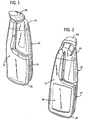
- Figure 1 shows a perspective view from the front of a bottle according to the invention.
- Figure 2 shows a perspective view from the rear of the bottle of Fig. 1.
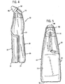
- Figure 3 shows a perspective exploded view of the bottle of Fig. 1.
- Figure 4 shows a right side view of the bottle of FIG. 1.
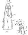
- Figure 5 shows a rear view of the bottle of Fig. 1.
- Figure 6 shows a front view of the bottle of Fig. 1.
- Figure 7 shows a partial view of the top of the bottle of Fig. 1 with the cap being stalled on the bottle.
- Figure 8 shows a partial view of the top of the bottle of Fig. 1.
- Figure 9 shows a bottom view of the nozzle of the bottle of Fig. 1.
- a two chamber bottle indicated generally at 10, according to the invention.
- the bottle 10 is assembled from four parts: a first chamber 20, a second chamber 40, an overcap 70 and a nozzle 80.
- these parts in particular, the first chamber 20, the second chamber 40, and the overcap 70
- a protective cap 90 is also provided for covering the nozzle 80 of the bottle 10 during shipping and storage.
- All of the components of the bottle 10 and the cap 90 can be molded from a suitable thermoplastic material such as polyethylene and polypropylene, and any of the components may be pigmented as desired with conventional pigments suitable for plastic materials.
- the first chamber 20 and the second chamber 40 are molded from high density polyethylene
- the overcap 70 and cap 90 are molded from polypropylene
- the nozzle 80 is molded from polyethylene.
- the walls of the first chamber 20 and the second chamber 40 are approximately 1 millimeter thick; however, in certain embodiments, the wall thickness may vary as described below.
- the first chamber 20 and the second chamber 40 each have a filling level of about 375 milliliters and a brimful level of 400 milliliters.
- the first chamber 20 includes a lower section 22 and an upper section 32.
- the lower section 22 of the first chamber 20 includes an inner mating wall 24, an upper wall 25 and an exterior wall 26.
- the upper section 32 of the first chamber 20 includes an inner wall 34, a lower wall 35, a top wall 37, and an exterior wall 36.
- the top wall 37 has a recesse area 37a on its perimeter and an upwardly extending cylindrical spout 38 defining a first exit opening with outwardly extending circumferential ribs 39.
- the first chamber 20 typically contains a first liquid, but is suitable for all flowable compositions. In the description below, a first liquid will be described for the purposes of illustration.
- the term "flowable composition” includes liquids, solutions, suspensions, emulsions, gases and any other forms of matter referred to or known as a "liquid” or a “fluid”, as well as other flowable compositions, such as powders (e.g., a carpet cleaning formula).
- the first and the second flowable compositions may be materials of the same physical character, or of different kinds.
- each of the first and second flowable compositions would comprise liquids.
- the first flowable composition could take the form of a liquid
- the second flowable composition could (for example) take the form of a powder.
- the flowable composition in either chamber could, prior to mixing with the flowable composition in the other chamber, also comprise a combination of two or more flowable compositions (e.g., an aerosol containing a gas and liquid).
- the second chamber 40 includes a lower section 42 and an upper section 52.
- the lower section 42 of the second chamber 40 includes an inner mating wall 44, an upper wall 45 and an exterior wall 46.
- the upper section 52 of the second chamber 40 includes an inner wall 54, a lower wall 55, a top wall 57, and an exterior wall 56.
- the top wall 57 has a recessed area 57a on its perimeter and an upwardly extending cylindrical spout 58 defining a second exit opening with outwardly extending circumferential ribs 59.
- the second chamber 40 typically contains a second liquid, but is suitable for all flowable compositions as described above. In the description below, a second liquid will be described for the purposes of illustration.
- the overcap 70 of the bottle 10 includes a top surface 71 and a skirt 73 extending downwardly from the top surface 71.
- the skirt 73 terminates in a lower edge 76.
- An annular upwardly extending first exit opening 72 and an annular upwardly extending second exit opening 74 are formed on the top surface 71 of the overcap 70.
- the nozzle 80 of the bottle 10 includes a top surface 88a and a skirt 89a extending downwardly from the top surface 88a, and a top surface 88b and a skirt 89b extending downwardly from the top surface 88b.
- the skirts 89a and 89b are joined by a bridging section 89c.
- the skirt 89a terminates in an annular rim 81 at its bottom, and the skirt 89b terminates in an annular rim 82 at its bottom.
- a first annular orifice 84 extends upwardly from the top surface 88a of the nozzle 80, and a second orifice 85 extends upwardly from the top surface 88b of the nozzle 80.
- An outwardly extending raised area 87 is provided on the lower periphery of the nozzle 80.
- the protective cap 90 includes a generally oval top surface 94 and a skirt 95 extending downwardly at an outward angle from the periphery of the top surface 94.
- the lower periphery of the skirt 95' has an outwardly extending section 92.
- the assembly of the bottle 10 is best described with reference to Figure 3.
- the first chamber 20, the second chamber 40, the overcap 70 and the nozzle 80 are all preferably manufactured from polyethylene or polypropylene and therefore, may be assembled together using conventional adhesives suitable for bonding polyethylene and polypropylene.
- Blends of adhesives such as a blend of a fast curing adhesive and a slow curing adhesive, can be advantageous.
- Other means for assembling the components are also suitable such as friction welding, ultrasonic welding, snap fitting, and other conventional techniques. Those skilled in the art will contemplate other means for bringing chamber surfaces into contact or into adjoining relationship.
- the first chamber 20 and the second chamber 40 are adjoined to each other (using, for example, adhesive) at the inner mating wall 24 of the first chamber 20 and the inner mating wall 44 of the second chamber 20.
- the inner mating wall 24 of the first chamber 20 and the inner mating wall 44 of the second chamber 20 may include means for aligning the first chamber 20 and the second chamber 40 during assembly such as a groove on the inner mating wall 24 of the first chamber 20 and a complementary outwardly extending rib on the inner mating wall 44 of the second chamber 20.
- a front wall 12, side walls 13, 14, a rear wall 15 and a flat supporting surface 16 for the bottle 10 are defined as shown in Figures 1-2 and 4-5.
- Any of the walls of the bottle may include suitable labeling, such as label 99 on the rear wall 15 in Fig. 2.
- first chamber 20 and the second chamber 40 are adjoined together, at least a portion of the inner wall 34 of the upper section 32 of the first chamber 20 and at least a portion of the inner wall 54 of the upper section 52 of the second chamber 40 adjoin each other, and preferably, the entire inner wall 34 of the upper section 32 of the first chamber 20 and the entire inner wall 54 of the upper section 52 of the second chamber 40 adjoin each other.
- an adhesive may be used to create a bond between the inner wall 34 of the upper section 32 of the first chamber 20 and the inner wall 54 of the upper section 52 of the second chamber 40.
- the lower wall 35 of the upper section 32 of the first chamber 20 adjoins at least a portion of the upper wall 45 of the lower section 42 of the second chamber 40, and preferably, the entire lower wall 35 of the upper section 32 of the first chamber 20 adjoins the entire upper wall 45 of the lower section 42 of the second chamber 40.
- the lower wall 35 of the upper section 32 of the first chamber 20 and the upper wall 45 of the lower section 42 of the second chamber 40 are adjoined together using an adhesive.
- the lower wall 55 of the upper section 52 of the second chamber 40 adjoins at least a portion of the upper wall 25 of the lower section 22 of the first chamber 20, and preferably, the entire lower wall 55 of the upper section 52 of the second chamber 40 adjoins the entire upper wall 25 of the lower section 22 of the first chamber 20.
- the lower wall 55 of the upper section 52 of the second chamber 40 and the upper wall 25 of the lower section 22 of the first chamber 20 are adjoined together using an adhesive.
- the lower wall 35 of the upper section 32 of the first chamber 20 has a first shape complementary to the upper wall 45 of the lower section 42 of the second chamber 40
- the lower wall 55 of the upper section 52 of the second chamber 40 has a second shape complementary to the upper wall 25 of the lower section 22 of the first chamber 20.
- the first shape and the second shape are different.
- the first shape and the second shape can be varied to provide for different flow rates from the first chamber 20 and the second chamber 40 and thereby provide for equal dispensing from the bottle 10.
- the overcap 70 is adjoined to the first chamber 20 and the second chamber 40.
- the lower edge 76 of the skirt 73 of the overcap 70 may be snap fit to the recessed area 37a of the top wall 37 of the first chamber 20 and to the recessed area 57a of the top wall 57 of the second chamber 40. Suitable adhesives can also be used if desired.
- the first exit opening 72 of the overcap 70 is placed in fluid communication with the upwardly extending cylindrical spout 38 of the first chamber 20 and the second exit opening 74 is placed in fluid communication with the upwardly extending cylindrical spout 58 of the second chamber 40.
- the spout 38 of the first chamber 20 and the spout 58 of the second chamber 40 may be arranged on an offset fashion as in Figure 3 such that the overcap 70 can only be placed on the first chamber 20 and the second chamber 40 in one manner.
- the nozzle 80 may then be assembled to the overcap 70.
- a snap fit between the annular rims 81, 82 at the bottom of the skirts 89a, 89b of the nozzle 80 and the first exit opening 72 and the second exit opening 74 respectively of the overcap 70 provides for a connection. Suitable adhesives can also be used, if desired.
- the first exit opening 72 of the overcap 70 is placed in fluid communication with the first orifice 84 of the nozzle 80 and the second exit opening 74 of the overcap 70 is placed in fluid communication with the second orifice 85 of the nozzle 80.
- the nozzle 80 could be left out of the bottle construction, and dispensing could occur directly from the first exit opening 72 of the overcap 70 and the second exit opening 74 of the overcap 70.
- the first orifice 84 and the second orifice 85 of the nozzle 80 can be configured to provide parallel streams of the first liquid and the second liquid.
- the first orifice 84 and the second orifice 85 of the nozzle 80 are in the same plane or parallel planes and are spaced apart about 4 millimeters.
- the first orifice 84 and the second orifice 85 of the nozzle 80 do not share a common wall. Spacing between the first orifice 84 and the second orifice 85 of the nozzle 80 limits contamination between the first liquid and the second liquid before and during dispensing because the streams are parallel, and also assures that mixing of the first liquid and the second liquid occurs on the surface being cleaned, and not before application to the surface.
- the fluid paths leading to the first orifice 84 and the second orifice 85 of the nozzle 80 can also be configured to provide streams of the first liquid and the second liquid that converge at a distance from the first orifice 84 and the second orifice 85 of the nozzle 80.
- the first exit opening 72 of the overcap 70 and the first orifice 84 of the nozzle 80 are eccentric
- the second exit opening 74 of the overcap 70 and the second orifice 85 of the nozzle 80 are eccentric.
- the axis of the first exit opening 72 of the overcap 70 is not coaxial with the axis of the first orifice 84 of the nozzle 80, and the axis of the second exit opening 74 of the overcap 70 is not coaxial with the axis of the second orifice 85 of the nozzle 80.
- the fluid paths leading to the first orifice 84 and the second orifice 85 of the nozzle 80 can be tapered.
- the streams of the first liquid and the second liquid may converge at a distance from the first orifice 84 and the second orifice 85 of the nozzle 80 even though the first orifice 84 and the second orifice 85 of the nozzle 80 are in the same or parallel planes.
- the cap 90 is configured to be removable as shown in Figure 7 and is held onto the nozzle 80 by way of a press fit between the outwardly extending raised area 87 provided on the lower periphery of the nozzle 80 and the outwardly extending section 92 of the skirt 95 of the cap 90.
- the cap 90 covers and seals the first orifice 84 and the second orifice 85 of the nozzle 80 of the bottle 10 during shipping and storage, and is removed when the first liquid and the second liquid are dispensed from the bottle 10.
- the assembled bottle 10 has several very significant advantages.
- the bottle 10 has several structural relationships that provide for even dispensing of the first liquid from the first chamber 20 and the second liquid from the second chamber 40.
- the bottle 10 provides for a horizontal orientation of the first chamber 20 and the second chamber 40.
- the inner wall 34 of the upper section 32 of the first chamber 20 extends from the front wall 12 to the rear wall 15 of the bottle 10
- at least a portion of the inner wall 54 of the upper section 52 of the second chamber 40 extends from the front wall 12 to the rear wall 15 of the bottle 10
- at least a portion of the inner mating wall 24 of the first chamber 20 and at least a portion of the inner mating wall 44 of the second chamber 40 extend between the side walls 13,14 of the bottle.
- a first axis of the first exit opening 72 (and associated first orifice 84 of the nozzle 80) and a second axis of the second exit opening 74 (and associated second orifice 85 of the nozzle 80) are tilted toward the front wall 12 of the bottle 10.
- a user's thumb provides more pounds per square inch of pressure than do fingers which are spread out over a larger surface area.
- adjustments can be made to compensate for the difference in thumb pressure and finger pressure and achieve equal dispensing.
- the surface area of the exterior wall 26 of the lower section 22 of the first chamber 20 and the surface area of the exterior wall 46 of the lower section 42 of the second chamber 40 can be varied to encompass a larger or smaller portion the front wall 12 and the rear wall 15 of the bottle.
- the portion of the exterior wall 26 of the lower section 22 of the first chamber 20 that comprises part of the front wall 12 of the bottle 10 may have at least one half of the surface area of the portion of the exterior wall 36 of the upper section 32 of the first chamber 20 that comprises part of the front wall 12 of the bottle 10 and the portion of the exterior wall 56 of the upper section 52 of the second chamber 40 that comprises part of the front wall 12 of the bottle 10 combined.
- the portion of the exterior wall 46 of the lower section 42 of the second chamber 40 that comprises part of the rear wall 15 of the bottle 10 may have at least one half of the surface area of the portion of the exterior wall 56 of the upper section 52 of the second chamber 40 that comprises part of the rear wall 15 of the bottle 10 and the portion of the exterior wall 36 of the upper section 32 of the first chamber 20 that comprises part of the rear wall 15 of the bottle 10 combined.
- Another adjustment that can be made to compensate for the difference in thumb pressure and finger pressure and achieve equal dispensing is to provide for varying wall thicknesses in the first chamber and the second chamber.
- the first chamber may have a greater wall thickness than the second chamber in order to provide more resistance to a user's thumb than to a user's fingers when dispensing the two liquids.
- the thumb-on-top orientation also allows for other modifications to account for the differential force between a user's thumb and a user's fingers.
- the modifications include: (1) having the first exit opening 72 (and/or associated first orifice 84 of the nozzle 80) and the second exit opening 74 (and/or associated second orifice 85 of the nozzle 80) have different transverse cross-sectional areas (i.e., larger opening size on the thumb side); (2) using a first liquid and a second liquid with different viscosities (i.e., a thicker formula on the thumb side); (3) using a first liquid and a second liquid having different specific gravities (i.e., less dense formula on the thumb side); (4) decreasing the transverse cross-sectional areas along the length of the fluid path from the first chamber to the first exit opening and/or along the length of the fluid path from the second chamber to the second exit opening (i.e., the fluid paths taper toward the exit openings); and (5) decreasing, increasing and then decreasing the transverse cross-sectional areas along the
- Modifications of the size of the first exit opening 72 (and/or associated first orifice 84 of the nozzle 80) and the second exit opening 74 (and/or associated second orifice 85 of the nozzle 80) can also provide for easier dispensing as larger openings tend to decrease back pressure on dispensing.
- the horizontal orientation of the two chamber bottle when in use is also achieved by the configuration of the first exit opening 72 and the second exit opening 74.
- the first axis of the first exit opening 72 forms less than a 90 degree angle in relation to the flat supporting surface 16 of the bottle 10 and the second axis of the second exit opening 74 also forms less than a 90 degree angle in relation to the flat supporting surface 16 of the bottle 10. Further, the first axis of the first exit opening 72 and the second axis of the second exit opening 74 are tilted toward the front wall 12 of the bottle 10.
- an imaginary line extending from the first axis of the first exit opening 72 to the second axis of the second exit opening 74 forms an angle of less than 90 degrees with the inner mating wall 24 of the first chamber 20.
- the first exit opening 72 is arranged in a side by side relationship with the second exit opening 74 when the bottle 10 is viewed from the front.
- the first exit opening 72 may also be arranged in a side by side relationship with the second exit opening 74 in a offset manner when the bottle 10 is viewed from the front.
- the second exit opening 74 is not directly behind the first exit opening 72.
- a left handed user and a right handed user handle the bottle 10 with a thumb on the front wall 12 of the bottle
- This orientation provides an ergonomically advantageous greater range of motion for the user than a vertically oriented bottle provides.
- lateral motion of the wrist is not constrained when using the bottle 10, especially when the bottle 10 is used to deliver the two liquids under the rim of a toilet bowl.
- the bottle 10 may include a pair of two-piece closures, known in the art as "push-pull" closures, for sealing the contents within the two chamber bottle.
- Each two piece closure comprises an inner cap and an outer fitment.
- the inner cap has a hollow, reduced diameter spout which is closed at its top and has a circumferential sealing bead located below the top.
- the spout further includes at least one opening therein which is located between its closed top and the circumferential sealing bead.
- the outer fitment is hollow and has an upwardly extending, reduced diameter portion whose top is open.
- the fitment also has a peripheral sealing bead on the internal surface of its reduced diameter portion.
- the inner cap is secured to an opening leading from the chamber.
- the fitment is then pushed into place over top of the inner cap so that the internally located sealing ring of the outer fitment is located below the extemally located sealing bead of the inner cap, and the external surface of the uppermost portion of the spout of the inner cap comes into sealing engagement with the inner surface of the upwardly extending, reduced diameter portion of the external fitment.
- the fitment is pulled upwardly. This removes the spout of the inner cap from its sealing engagement with the inner surface of the reduced diameter portion of the fitment.
- the contents may then flow from the interior of the chamber, through the interior of the reduced diameter spout of the inner cap, through at least one opening in the spout, and finally through the open upper end of the fitment.
- One example "push-pull" closure construction can be found in U.S. Patent No. 3,032,240 which is incorporated herein by reference.
- the two chamber bottle 10 is used to hold and dispense a two part liquid cleaning composition according to the invention which is suitable for cleaning hard surfaces, such as tile, wash bowls, toilets, bathtubs, showers, sinks, countertops, walls and floors, particularly in kitchen and bathroom areas.
- the two chamber bottle 10 may be used to hold and dispense a two part powdered cleaning composition which is suitable for cleaning carpeted surfaces.
- the two part cleaning composition is a liquid particularly useful for cleaning toilet bowls and includes: (i) a first aqueous liquid comprising a base selected from the group consisting of carbonates, bicarbonates, sesquicarbonates, and mixtures thereof, and (ii) a second aqueous liquid comprising an acid selected from the group consisting of sulfuric acid, hydrochloric acid, phosphoric acid, nitric acid, boric acid, formic acid, acetic acid, malic acid, maleic acid, succinic acid, tartaric acid, lactic acid, glutaric acid, glycolic acid, fumaric acid, benzoic acid, citric acid, sulfamic acid, oxalic acid, and mixtures thereof.
- a first aqueous liquid comprising a base selected from the group consisting of carbonates, bicarbonates, sesquicarbonates, and mixtures thereof
- a second aqueous liquid comprising an acid selected from the group consisting of sulfuric acid, hydrochloric acid, phosphoric
- the first liquid and the second liquid are kept physically separated (e.g., in first chamber 20 and in second chamber 40 of bottle 10) until dispensing.
- the first liquid may include about 0.001 percent by weight to about 4 percent by weight based on the total weight of the first liquid of a surfactant system which consists of all surfactants in the first liquid.
- the second liquid may include about 0.001 percent by weight to about 4 percent by weight based on the total weight of the second liquid of a surfactant system which consists of all surfactants in the second liquid. At least one of the first liquid and the second liquid includes a surfactant system at these levels.
- the first liquid may include about 0.001 percent by weight to about 3 percent by weight of a foam inhibitor, based on the total weight of the first liquid.
- the second liquid may include about 0.001 percent by weight to about 3 percent by weight of a foam inhibitor, based on the total weight of the second liquid. At least one of the first liquid and the second liquid includes a foam inhibitor at these levels.
- the two part cleaning composition includes: (i) a first liquid comprising a base selected from the group consisting of carbonates, bicarbonates, sesquicarbonates, and mixtures thereof, and (ii) a second liquid comprising an acid selected from the group consisting of sulfuric acid, hydrochloric acid, phosphoric acid, nitric acid, boric acid, formic acid, acetic acid, malic acid, maleic acid, succinic acid, tartaric acid, lactic acid, glutaric acid, glycolic acid, fumaric acid, benzoic acid, citric acid, sulfamic acid, oxalic acid, and mixtures thereof.
- a first liquid comprising a base selected from the group consisting of carbonates, bicarbonates, sesquicarbonates, and mixtures thereof
- a second liquid comprising an acid selected from the group consisting of sulfuric acid, hydrochloric acid, phosphoric acid, nitric acid, boric acid, formic acid, acetic acid, malic acid, maleic acid
- the first liquid and the second liquid are kept physically separated (e.g., in first chamber 20 and in second chamber 40 of bottle 10) until dispensing.
- the first liquid may include about 0.001 percent by weight to about 4 percent by weight based on the total weight of the first liquid of a surfactant system which consists of all surfactants in the first liquid.
- the second liquid may include about 0.001 percent by weight to about 4 percent by weight based on the total weight of the second liquid of a surfactant system which consists of all surfactants in the second liquid. At least one of the first liquid and the second liquid includes a surfactant system at these levels.
- the first liquid may include about 0.001 percent by weight to about 1 percent by weight of a silicone foam inhibitor, based on the total weight of the first liquid.
- the second liquid may include about 0.001 percent by weight to about 1 percent by weight of a silicone foam inhibitor, based on the total weight of the second liquid. At least one of the first liquid and the second liquid includes a silicone foam inhibitor at these levels.
- the first liquid may include about 0.001 percent by weight to about 1 percent by weight of a fragrance comprising at least one oil, based on the total weight of the first liquid.
- the second liquid may include about 0.001 percent by weight to about 1 percent by weight of a fragrance comprising at least one oil, based on the total weight of the second liquid. At least one of the first liquid and the second liquid includes a fragrance comprising at least one oil at these levels.
- the first liquid and the second liquid When the first liquid and the second liquid are dispensed on a surface such as a toilet bowl, the first liquid and the second liquid mix thereby initiating a chemical reaction between the base and the acid.
- Carbon dioxide gas released from the base instantaneously creates a foam in the mixture.
- the foam inhibitor then quickly breaks the foam, and the remaining gas generated creates a physical/mechanical cleaning action in the mixture and produces noise when bubbles in the mixture break.
- the gas generation also promotes the release of fragrance into the air thereby freshening the air in the vicinity of the surface being cleaned.
- the amounts of the surfactant system, the foam inhibitor and the optional fragrance in the two part cleaning composition are one critical aspect of the invention.
- High levels of surfactant would create large volumes of a slowly breaking stable foam which would significantly limit the physical/mechanical cleaning action in the mixture of the two liquids. Thus, excess foam levels hinder cleaning performance.
- Large amounts of slowly breaking stable foam would also limit noise generation in the mixture of the two liquids thereby decreasing a user's audible cue that physical/mechanical cleaning action is occurring.
- Large amounts of slowly breaking foam would also limit the release of any fragrance into the air as gas generation would only serve to build foam and would not be used for fragrance release.
- the base in the first liquid comprises a base selected from the group consisting of carbonates, bicarbonates, sesquicarbonates, and mixtures thereof.
- suitable bases include sodium carbonate, potassium carbonate, magnesium carbonate, calcium carbonate, ammonium carbonate, sodium bicarbonate, potassium bicarbonate, magnesium bicarbonate, calcium bicarbonate, ammonium bicarbonate, sodium sesquicarbonate, potassium sesquicarbonate, magnesium sesquicarbonate, calcium sesquicarbonate, ammonium sesquicarbonate, and mixtures thereof.
- the base is selected from sodium carbonate, sodium bicarbonate and mixtures thereof, and is dissolved in water included in the first liquid.
- the base is a mixture of sodium carbonate and sodium bicarbonate wherein the sodium carbonate buffers decomposition of the sodium bicarbonate.
- the first liquid comprises about 2 percent by weight to about 20 percent by weight of the base based on the total weight of the first liquid, and most preferably, the first liquid comprises about 2 percent by weight to about 10 percent by weight of the base based on the total weight of the first liquid.
- the acid in the second liquid comprises an acid selected from the group consisting of sulfuric acid, hydrochloric acid, phosphoric acid, nitric acid, boric acid, formic acid, acetic acid, malic acid, maleic acid, succinic acid, tartaric acid, lactic acid, glutaric acid, glycolic acid, fumaric acid, benzoic acid, citric acid, sulfamic acid, oxalic acid, and mixtures thereof.
- the acid is selected from citric acid, sulfamic acid, oxalic acid, and mixtures thereof, and most preferably, the acid is a mixture of citric acid, sulfamic acid, and oxalic acid.
- the acid is dissolved in water included in the second liquid.
- the second liquid comprises about 5 percent by weight to about 25 percent by weight of the acid based on the total weight of the second liquid, and most preferably, the second liquid comprises about 10 percent by weight to about 20 percent by weight of the acid based on the total weight of the second liquid.
- the second liquid comprises about 2 percent by weight to about 10 percent by weight of citric acid based on the total weight of the second liquid, and about 5 percent by weight to about 15 percent by weight of sulfamic acid based on the total weight of the second liquid.
- the surfactant system present in the first liquid and/or the second liquid may be a single surfactant or a mixture of surfactants.
- Anionic, nonionic, amphoteric, zwitterionic surfactants and mixtures thereof are suitable in the surfactant system of the present invention, and are present in an amount from about 0.001 percent by weight to about 4 percent by weight based on the total weight of the first liquid or the second liquid, and preferably, an amount from about 0.001 percent by weight to about 2 percent by weight based on the total weight of the first liquid or the second liquid.
- Anionic surfactants, nonionic surfactants and mixtures thereof are especially preferred.
- anionic surfactants include water-soluble alkyl or alkylaryl compounds, the alkyl having from about 8 to about 22 carbons, including a sulfate or sulfonate substituent group that has been base-neutralized, typically to provide an alkali metal (e.g., sodium or potassium) cation, including, for example: (1) alkyl and alkylaryl sulfates and sulfonates having preferably 8 to 18 carbons in the alkyl group, which may be straight or branched chain, e.g., sodium lauryl sulfate and sodium dodecylbenzene sulfonate; (2) alphaolefin aryl sulfonates preferably having from about 10 to 18 carbons in the olefin, e.g:, sodium C 14-16 olefin sulfonate; and (3) alkyl ether sulfates such as sodium lauryl ether sulfate.
- Non-limiting examples of non-ionic surfactants include (1) fatty alcohol alkoxylates, especially the ethoxylates, wherein the alkyl group has from 8 to 22, preferably 12 to 18, carbons, and typically 6 to 15 moles of alkoxide per molecule; (2) fatty acid alkoxylates having from about 6 to about 15 moles of alkoxylate, especially the ethoxylate; (3) alkylphenoxy alkoxylates, especially the ethoxylates, containing 6 to 12 carbons, preferably octyl or nonyl, in the alkyl, and having about 5 to 25, preferably 5 to 15 moles alkylene oxide per molecule; (4) condensates of ethylene oxide with a hydrophobic base formed by condensation of propylene oxide with propylene glycol;.
- condensates of ethylene oxide with an amine or amide (6) condensates of ethylene oxide with an amine or amide; (6) fatty amine oxides; (7) alkylolamides; and (8) low cloud point nonionic surfactants including, for example, ethoxylated-propoxylated alcohols.
- Preferred nonionic surfactants are the fatty alcohol ethoxylates.
- the foam inhibitor present in the first liquid and/or the second liquid may selected from the group consisting of silicone materials, fragrance oils, glycol ethers, and mixtures thereof.
- the foam inhibitor is present in an amount from about 0.001 percent by weight to about 3 percent by weight based on the total weight of the first liquid or the second liquid, preferably, in an amount from about 0.001 percent by weight to about 2 percent by weight based on the total weight of the first liquid or the second liquid, and most preferably, in an amount from about 0.001 percent by weight to about 1 percent by weight based on the total weight of the first liquid or the second liquid.
- the foam inhibitor may be a silicone material present in the first liquid and/or the second liquid.
- the silicone material employed as the foam inhibitor can be an alkylated polysiloxane material wherein the side chain groups are alkyl, aryl, or mixed alkyl and aryl groups.
- Specific examples of such silicone materials include dimethyl polysiloxanes, diethyl polysiloxanes; dipropyl polysiloxanes; dibutyl polysiloxanes; methylethyl polysiloxanes; phenylmethyl polysiloxanes; and the like.
- the dimethyl polysiloxanes are particularly useful herein due to their low cost and ready availability.
- a second type of silicone foam inhibitor useful in the first liquid and/or the second liquid comprises a mixture of an alkylated siloxane of the type disclosed above and silica.
- the foam inhibitor may be a fragrance oil present in the first liquid and/or the second liquid.
- the foam inhibition may come from the silicone materials and/or glycol ethers present in the first liquid and/or the second liquid.
- the fragrance present in the first liquid and/or the second liquid may comprise a single fragrance oil or a mixture including at least one fragrance oil. Any fragrance that does not significantly interfere with the cleaning properties of the composition is suitable, and the fragrance (if present for fragrancing purposes) is present in an amount from about 0.001 percent by weight to about. 1 percent by weight based on the total weight of the first liquid or the second liquid, and preferably, in an amount from about 0.001 percent by weight to about 0.6 percent by weight based on the total weight of the first liquid or the second liquid.
- the fragrance includes oils that act as a foam inhibitor
- a portion of the fragrance oil is not solubilized in the first liquid or the second liquid such that the portion of fragrance oil that is not solubilized (typically in the form of droplets) can act as a foam inhibitor.
- the foam inhibitor may be a glycol ether present in the first liquid and/or the second liquid.
- foam inhibiting glycol ethers are represented by the formula R 1 - O - R 2 wherein R 1 is a C 1 -C 8 linear, branched or cyclic alkyl or alkenyl substituted with -OH and R 2 is a C 1 -C 8 linear, branched or cyclic alkyl or alkenyl optionally substituted with -OH or -OR 3 wherein R 3 is a C 1 -C 8 linear, branched or cyclic alkyl or alkenyl.
- R 1 is selected from -CH 2 CH 2 OH, -CH 2 CHOHCH 3 and -CH 2 CH 2 CH 2 OH and R 2 is a linear C 1 -C 8 alkyl optionally substituted with -OH or OR 3 wherein R 3 is a C 1 -C 8 linear alkyl. More preferably, R 1 is selected from -CH 2 CHOHCH 3 and -CH 2 CH 2 CH 2 OH and R 2 is a linear C 1 -C 8 alkyl substituted with -OR 3 wherein R 3 is a C 1 -C 8 linear alkyl.
- Suitable glycol ethers include ethylene glycol n-hexyl ether, ethylene glycol n-butyl ether, dipropylene glycol methyl ether, dipropylene glycol n-butyl ether, propylene glycol n-butyl ether and propylene glycol n-propyl ether. Preferred is dipropylene glycol n-butyl ether.
- the glycol ethers are preferably lower in water solubility.
- Organic solvents may also be present in the first liquid and/or the second liquid to enhance the cleaning efficiency of the two part composition of the invention.
- organic solvents are well known to those of ordinary skill in the art.
- Preferred solvents include lower alkanols such as ethanol.
- the solvent is generally present in an amount from about 0.001 percent by weight to about 5 percent by weight based on the total weight of the first liquid or the second liquid, and preferably, in an amount from about 0.001 percent by weight to about 2 percent by weight based on the total weight of the first liquid or the second liquid.
- a hydrotrope may also be present in the first liquid and/or the second liquid to assist in blending of surfactants and solvents (if present) and to raise the cloud point of the first liquid and/or the second liquid. Therefore, the amount of hydrotrope is dependent upon the concentration of the solvents and surfactant.
- Example hydrotropes are alkali metal salts of aromatic sulfonates.
- a preferred hydrotrope is sodium xylene sulfonate.
- Other exemplary hydrotropes include sodium butyl monoglycol sulfate, sodium toluene sulfonate and sodium cumene sulfonate.
- the hydrotrope When present in the first liquid and/or the second liquid, the hydrotrope is generally present in an amount from about 0.001 percent by weight to about 5 percent by weight based on the total weight of the first liquid or the second liquid, and preferably, in an amount from about 0.001 percent by weight to about 2 percent by weight based on the total'weight of the first liquid or the second liquid.
- a thickener may be used to increase the viscosity of the first liquid and/or the second liquid and thereby achieve the controlled even dispensing described above.
- any added thickener should not be present in so high an amount such that there is detraction from the cleaning action of the two part cleaning composition.
- the amount of the thickener will depend on the nature of the thickener and the other components in the two part composition, and it may be that the other components in the composition, in addition to the other properties, also act as the thickener for the purpose of giving the appropriate viscosity to the first liquid and the second liquid of the two part composition.
- the thickener When present in the first liquid and/or the second liquid, the thickener is generally present in an amount from about 0.001 percent by weight to about 1 percent by weight based on the total weight of the first liquid or the second liquid.
- the thickener can be organic polymeric materials, inorganic compounds or mixtures thereof. Suitable organic polymeric thickeners are selected from at least one of a biopolymer, a cross-linked polyacrylate, and a modified polyacrylate, or mixtures thereof.
- the biopolymers can be xanthan or whelan gum.
- Suitable inorganic thickeners are selected from at least one of smectite clay, synthetic hectolite, alumino-silicate and attapulgite.
- Foam stabilizers may also be used in the first liquid and/or the second liquid.
- Suitable foam stabilizers include cellulosic materials such as alkylcelluloses and hydroxyalkylcelluloses (e.g., hydroxy ethyl cellulose).
- the foam stabilizer is generally present in an amount from about 0.001 percent by weight to about 1 percent by weight based on the total weight of the first liquid or the second liquid.
- Dyes may also be used in the first liquid and/or the second liquid to achieve a desired hue, but without compromising the suitability of the product.
- the dye When present in the first liquid and/or the second liquid, the dye is generally present in an amount from about 0.0001 percent by weight to about 1 percent by weight based on the total weight of the first liquid or the second liquid.
- the first liquid and the second liquid of the cleaning composition of the invention are aqueous compositions.
- Water will usually comprise at least 60 percent, and preferably at least 80 percent by weight of the first liquid and the second liquid of the cleaning composition.
- a two part cleaner suitable for cleaning a toilet bowl was prepared by mixing the following ingredients in Table 1 in separate containers (one designated Basic Side and one designated Acidic Side).
- Basic Side Acidic Side Ingredient Wt. % Ingredient Wt. % Water 94.9750 Water 89.9975 Sodium Lauryl Ether Sulfate (Anionic Surfactant) 0.0150 Citric Acid 5.0000 Ethoxylated C 12 -C 15 Alcohol (Non-Ionic Surfactant) 0.0050 Sulfamic Acid 5.0000 Fragrance 0.0025 Acid Blue #9 50% Liquid Dye 0.0025 Ethyl Alcohol (Solvent) 0.0025 Sodium Bicarbonate 5.0000 TOTAL 100.00 TOTAL 100.00 TOTAL 100.00
- the sodium lauryl ether sulfate anionic surfactant used was a commercially available surfactant sold under the trade name "Empicol ESB 70F”.
- the ethoxylated C 12 -C 15 alcohol non-ionic surfactant used was a commercially available surfactant sold under the trade name "Lutensol A08”.
- a two part cleaner suitable for cleaning a toilet bowl was prepared by mixing the following ingredients in Table 2 in separate containers (one designated Basic Side and one designated Acidic Side).
- Basic Side Acidic Side Ingredient Wt. % Ingredient Wt. % Water 92.7400 Water 83.9995 Polydimethylsiloxane (Antifoam) 0.0100 Citric Acid 5.0000 Ethyl Alcohol (Solvent) 0.2500 Sulfamic Acid 10.0000 Sodium Bicarbonate 6.5000 Oxalic Acid 0.5000 Sodium Carbonate 0.5000 Acid Blue #9 50% Liquid Dye 0.0005 Xanthan Gum (Thickener) 0.1000 Fragrance 0.4000 TOTAL 100.00 TOTAL 100.00
- the polydimethylsiloxane antifoam used was a commercially available silica filled polydimethylsiloxane sold under the trade name "SAG 10" by OSI Specialties.
- the xanthan gum used was commercially sold under the trade name "Kelzan ASX” by C.P. Kelco. When applied to a surface, an instantaneous fast breaking foam having audible fizzing was generated along with fragrancing in the vicinity of the surface.
- a two part cleaner suitable for cleaning a toilet bowl was prepared by mixing the following ingredients in Table 3 in separate containers (one designated Basic Side and one designated Acidic Side).
- Basic Side Acidic Side Ingredient Wt. % Ingredient Wt. % Water 90.1500 Water 84.3995 Sodium Xylene Sulfonate (Anionic Hydrotrope) 1.0000 Citric Acid 5.0000 Ethoxylated Propoxylated Alcohol (Non-Ionic Surfactant) 1.0000 Sulfamic Acid 10.0000 Fragrance 0.5000 Oxalic Acid 0.5000 Hydroxy Ethyl Cellulose (Foam Stabilizer) 0.0500 Acid Blue #9 50% Liquid Dye 0.0005 Polydimethylsiloxane (Antifoam) 0.2500 Xanthan Gum (Thickener) 0.1000 Xanthan Gum (Thickener) 0.0500 Sodium Bicarbonate 6.5000 Sodium Carbonate 0.5000 TOTAL 100.00 TOTAL 100.00
- the sodium xylene sulfonate anionic hydrotrope used was commercially available under the trade name "Stepanate SXS” from Stepan Chemicals.
- the ethoxylated propoxylated alcohol non-ionic surfactant used was a commercially available surfactant sold under the trade name "Eumulgin L” by Cognis Corp.
- the polydimethylsiloxane antifoam used was a commercially available silica filled polydimethylsiloxane sold under the trade name "SAG 10" by OSI Specialties.
- the xanthan gum used was commercially sold under the trade name "Kelzan ASX" by C.P. Kelco.
- the hydroxy ethyl cellulose used was available under the trade name "Natrosol 25.0 HHR” from Hercules. When applied to a surface, an instantaneous fast breaking foam having audible fizzing was generated along with fragrancing in the vicinity of the surface.
- a two part cleaner suitable for cleaning a toilet bowl was prepared by mixing the following ingredients in Table 4 in separate containers (one designated Basic Side and one designated Acidic Side).
- Basic Side Acidic Side Ingredient Wt. % Ingredient Wt. % Water 91.1500 Water 84.3995 40% Sodium Xylene Sulfonate (Anionic Hydrotrope) 1.0500 Citric Acid 5.0000 Ethoxylated Propoxylated Alcohol (Non-Ionic Surfactant) 0.3000 Sulfamic Acid 10.0000 Fragrance (Antifoam) 0.4000 Oxalic Acid 0.5000 Hydroxy Ethyl Cellulose (Foam Stabilizer) 0.0500 Acid Blue #9 50% Liquid Dye 0.0005 Xanthan Gum (Thickener) 0.0500 .
- Xanthan Gum (Thickener) 0.1000 Sodium Bicarbonate 6.5000 Sodium Carbonate 0.5000 TOTAL 100.00 TOTAL 100.00
- the sodium xylene sulfonate anionic hydrotrope used was commercially available under the trade name "Stepanate SXS” from Stepan Chemicals.
- the ethoxylated propoxylated alcohol non-ionic surfactant used was a commercially available surfactant sold under the trade name "Eumulgin L” by Cognis Corp.
- the xanthan gum used was commercially sold under the trade name "Kelzan ASX" by C.P. Kelco.
- the hydroxy ethyl cellulose used was available under the trade name "Natrosol 250 HHR” from Hercules. When applied to a surface, an instantaneous fast breaking foam having audible fizzing was generated along with fragrancing in the vicinity of the surface.
- a two part cleaner suitable for cleaning a toilet bowl was prepared by mixing the following ingredients in Table 5 in separate containers (one designated Basic Side and one designated Acidic Side).
- Basic Side Acidic Side Ingredient Wt. % Ingredient Wt. % Water 89.3000 Water 84.3995 40% Sodium Xylene Sulfonate (Anionic Hydrotrope) 1.5000 Citric Acid 5.0000 Ethoxylated Alcohol 0.2000 Sulfamic Acid 10.0000 Fragrance 0.4000 Oxalic Acid 0.5000 Hydroxy Ethyl Cellulose (Foam Stabilizer) 0.0500 Acid Blue #9 50% Liquid Dye 0.0005 Dipropylene glycol n-butyl ether (Antifoam) 1.5000 Xanthan Gum (Thickener) 0.1000 Xanthan Gum (Thickener) 0.0500 Sodium Bicarbonate 6.5000 Sodium Carbonate 0.5000 TOTAL 100.00 TOTAL 100.00
- the sodium xylene sulfonate anionic hydrotrope used was commercially available under the trade name "Stepanate SXS” from Stepan Chemicals.
- the ethoxylated alcohol non-ionic surfactant used was a commercially available surfactant sold under the trade name "Lutensol A08” by BASF Corp.
- the xanthan gum used was commercially sold under the trade name "Kelzan ASX” by C.P. Kelco.
- the hydroxy ethyl cellulose used was available under the trade name "Natrosol 250 HHR” from Hercules. When applied to a surface, an instantaneous fast breaking foam having audible fizzing was generated along with fragrancing in the vicinity of the surface.
- the invention provides a two part cleaning composition having foaming characteristics that do not limit the beneficial mechanical cleaning action of the chemical reaction of the two part cleaner.
- the two part cleaning composition also has an improved balance of foaming characteristics and air freshening characteristics such that the cleaner is advantageous in cleaning hard surfaces and freshening the air in the vicinity of the hard surfaces.
- the present invention also provides a two compartment container for dispensing two part cleaning compositions wherein the two components are evenly dispensed from the container.
- the container also provides for ergonomically advantageous dispensing positions.
- the invention relates to a liquid two part cleaning composition for hard surfaces such as a toilet bowl, and a bottle for dispensing the liquid two part cleaning composition.
Landscapes
- Engineering & Computer Science (AREA)
- Chemical & Material Sciences (AREA)
- Mechanical Engineering (AREA)
- Life Sciences & Earth Sciences (AREA)
- Chemical Kinetics & Catalysis (AREA)
- Oil, Petroleum & Natural Gas (AREA)
- Wood Science & Technology (AREA)
- Organic Chemistry (AREA)
- Containers And Packaging Bodies Having A Special Means To Remove Contents (AREA)
- Detergent Compositions (AREA)
Claims (22)
- Flasche (10) zur Abgabe von zwei fließfähigen Zusammensetzungen, wobei die Flasche umfasst:dadurch gekennzeichnet, dass sich die inneren Gegenwände (24, 44) zwischen den Seitenwänden (13, 14) erstrecken,eine erste Kammer (20) für eine erste fließfähige Zusammensetzung, wobei die erste Kammer (20) einen unteren Abschnitt (22) und einen oberen Abschnitt (32) hat, der untere Abschnitt (22) der ersten Kammer (20) eine innere Gegenwand (24) und eine Außenwand (26) hat, der obere Abschnitt (32) der ersten Kammer (20) eine Innenwand (34) und eine Außenwand (36) hat, der obere Abschnitt (32) der ersten Kammer (20) eine erste Ausgangsöffnung (38) umfasst; undeine zweite Kammer (40) für eine zweite fließfähige Zusammensetzung, wobei die zweite Kammer (40) einen unteren Abschnitt (42) und einen oberen Abschnitt (52) hat, der untere Abschnitt (42) der zweiten Kammer (40) eine innere Gegenwand (44) und eine Außenwand (46) hat, der obere Abschnitt (52) der zweiten Kammer (40) eine Innenwand (54) und eine Außenwand (56) hat, der obere Abschnitt (52) der zweiten Kammer (40) eine zweite Ausgangsöffnung (58) umfasst,
und einen ersten Auslass in Verbindung mit der ersten Auslassöffnung (38) und einen zweiten Auslass in Verbindung mit der zweiten Ausgangsöffnung (58), wobei der erste und zweite Auslass konfiguriert ist, um sowohl die erste als auch die zweite fließfähige Zusammensetzung in frontaler Richtung abzugeben, wobei die innere Gegenwand (24) der ersten Kammer (20) an die innere Gegenwand (44) der zweiten Kammer (40) grenzt, und dabei eine Vorderwand (12), Seitenwände (13,14) und eine Rückwand (15) für die Flasche (10) definiert;
und worin sich die Innenwände (34, 54) der oberen Abschnitte (32, 52) zwischen der Vorderwand (12) und der Rückwand (15) erstrecken. - Flasche (10) nach Anspruch 1, worin:mindestens ein Teil der Innenwand (34) des oberen Abschnitts der ersten Kammer (20) und mindestens ein Teil der Innenwand (54) des oberen Abschnitts der zweiten Kammer (40) aneinander stoßen.
- Flasche (10) nach Anspruch 1, worin:der untere Abschnitt der ersten Kammer eine obere Wand (25) umfasst,der untere Abschnitt der zweiten Kammer eine obere Wand (45) umfasst,der obere Abschnitt der ersten Kammer eine untere Wand (35) umfasst,der obere Abschnitt der zweiten Kammer eine untere Wand (55) umfasst,mindestens ein Teil der unteren Wand (35) des oberen Abschnitts der ersten Kammer an mindestens einen Teil der oberen Wand (45) des unteren Abschnitts der zweiten Kammer stößt, undmindestens ein Teil der unteren Wand (55) des oberen Abschnitts der zweiten Kammer an mindestens einen Teil der oberen Wand (25) des unteren Abschnitts der ersten Kammer stößt.
- Flasche (10) nach Anspruch 3, worin:die untere Wand (35) des oberen Abschnitts der ersten Kammer eine erste Form aufweist, die komplementär ist zur oberen Wand (45) des unteren Abschnitts der zweiten Kammer, die untere Wand (55) des oberen Abschnitts der zweiten Kammer eine zweite Form hat, die komplementär ist zur oberen Wand (25) des unteren Abschnitts der ersten Kammer, und die erste Form und die zweite Form unterschiedlich sind.
- Flasche (10) nach Anspruch 1, worin:eine erste Achse des ersten Auslasses einen Winkel von weniger als 90°, bezogen auf eine flache Stützfläche der Flasche (10) bildet,und eine zweite Achse des zweiten Auslasses einen Winkel von weniger als 90°, bezogen auf die flache Stützfläche der Flasche (10) bildet.
- Flasche (10) nach Anspruch 1, worin:die erste Achse und die zweite Achse zur Vorderwand der Flasche (10) hin geneigt sind.
- Flasche (10) nach Anspruch 1, worin:die Vorderwand (12) mindestens einen Teil der Außenwand (36) des oberen Abschnitts der ersten Kammer, mindestens einen Teil der Außenwand (56) des oberen Abschnitts der zweiten Kammer und mindestens einen Teil der Außenwand (26) des unteren Abschnitts der ersten Kammer umfasst.
- Flasche (10) nach Anspruch 7, worin:der Teil der Außenwand (26) des unteren Abschnitts der ersten Kammer mindestens eine Hälfte der Oberfläche des Teils der Außenwand (36) des oberen Abschnitts der ersten Kammer des Teils der Außenwand (56) des oberen Abschnitts der zweiten Kammer gemeinsam hat.
- Flasche (10) nach Anspruch 1, worin:die Rückwand (15) mindestens einen Teil der Außenwand (36) des oberen Abschnitts der ersten Kammer, mindestens einen Teil der Außenwand (56) des oberen Abschnitts der zweiten Kammer und mindestens einen Teil der Außenwand (46) des unteren Abschnitts der zweiten Kammer umfasst.
- Flasche (10) nach Anspruch 9, worin:der Teil der Außenwand (46) des unteren Abschnitts der zweiten Kammer mindestens eine Hälfte der Oberfläche des Teils der Außenwand (56) des oberen Abschnitts der zweiten Kammer und des Teils der Außenwand (36) des oberen Abschnitts der ersten Kammer gemeinsam hat.
- Flasche (10) nach Anspruch 1, worin:eine imaginäre Linie, die sich von einer ersten Achse der ersten Ausgangsöffnung (38) zu einer zweiten Achse der zweiten Ausgangsöffnung (58) erstreckt, einen Winkel von weniger als 90° mit der inneren Gegenwand (24) der ersten Kammer bildet.
- Flasche (10) nach Anspruch 1, worin:die erste Ausgangsöffnung (38) und die zweite Ausgangsöffnung (58) unterschiedliche diagonale Querschnittsflächen haben.
- Flasche (10) nach Anspruch 1, worin:die erste Ausgangsöffnung (38) und die zweite Ausgangsöffnung (58) mit Druck-Zug-Verschlüssen verschlossen sind.
- Flasche (10) nach Anspruch 1, worin:ein erster Flüssigkeitsweg sich von der ersten Kammer (20) zur ersten Ausgangsöffnung (38) erstreckt,ein zweiter Flüssigkeitsweg sich von der zweiten Kammer (40) zur zweiten Ausgangsöffnung (58) erstreckt, unddiagonale Querschnittsflächen entlang der Länge des ersten Flüssigkeitswegs von der ersten Kammer (20) zur ersten Ausgangsöffnung (38) kleiner werden, oder diagonale Querschnittsflächen entlang der Länge des zweiten Flüssigkeitswegs von der zweiten Kammer (40) zur zweiten Ausgangsöffnung (58) kleiner werden, oder diagonale Querschnittsflächen entlang der Länge des ersten Flüssigkeitswegs von der ersten Kammer (20) zur ersten Ausgangsöffnung (38) kleiner werden und diagonale Querschnittsflächen entlang der Länge des zweiten Flüssigkeitswegs von der zweiten Kammer (40) zur zweiten Ausgangsöffnung (58) kleiner werden.
- Flasche (10) nach Anspruch 1, worin:ein erster Flüssigkeitsweg sich von der ersten Kammer (20) zur ersten Ausgangsöffnung (38) erstreckt,ein zweiter Flüssigkeitsweg sich von der zweiten Kammer (40) zur zweiten Ausgangsöffnung (58) erstreckt, unddiagonale Querschnittsflächen entlang der Länge des ersten Flüssigkeitswegs von der ersten Kammer (20) zur ersten Ausgangsöffnung (38) in Folge kleiner werden, größer werden und kleiner werden, oder diagonale Querschnittsflächen entlang der Länge des zweiten Flüssigkeitsweges von der zweiten Kammer (40) zur zweiten Ausgangsöffnung (58) in Folge kleiner werden, größer werden und kleiner werden, oder diagonale Querschnittsflächen entlang der Länge des ersten Flüssigkeitswegs von der ersten Kammer (20) zur ersten Ausgangsöffnung (38) kleiner werden und diagonale Querschnittsflächen entlang der Länge des zweiten Flüssigkeitswegsvon der zweiten Kammer (40) zur zweiten Ausgangsöffnung (58) in Folge kleiner werden, größer werden und kleiner werden.
- Flasche (10) nach Anspruch 1, worin:die erste fließfähige Zusammensetzung und die zweite fließfähige Zusammensetzung unterschiedliche Viskositäten haben.
- Flasche (10) nach Anspruch 1, worin:die erste fließfähige Zusammensetzung und die zweite fließfähige Zusammensetzung unterschiedliche relative Dichten haben.
- Flasche (10) nach Anspruch 1, worin
die erste fließfähige Zusammensetzung und die zweite fließfähige Zusammensetzung flüssige Reiniger für harte Oberflächen sind. - Flasche (10) nach Anspruch 1, worin:die erste fließfähige Zusammensetzung und die zweite fließfähige Zusammensetzung pulverförmige Teppichreiniger sind.
- Flasche (10) nach Anspruch 1, worin:die erste Ausgangsöffnung (38) und die zweite Ausgangsöffnung (58) voneinander entfernt sind.
- Flasche (10) nach Anspruch 1, worin:die erste fließfähige Zusammensetzung und die zweite fließfähige Zusammensetzung den ersten und zweiten Auslass in parallelen Strömen verlassen.
- Flasche (10) nach Anspruch 1, worin:die erste fließfähige Zusammensetzung und die zweite fließfähige Zusammensetzung den ersten und zweiten Auslass in Strömen verlassen, die im Abstand von der Flasche zusammenlaufen.
Applications Claiming Priority (3)
| Application Number | Priority Date | Filing Date | Title |
|---|---|---|---|
| US216513 | 2002-08-09 | ||
| US10/216,513 US6758411B2 (en) | 2002-08-09 | 2002-08-09 | Dual bottle for even dispensing of two flowable compositions |
| PCT/US2003/024962 WO2004014760A1 (en) | 2002-08-09 | 2003-08-07 | Dual bottle for even dispensing of two flowable compositions |
Publications (2)
| Publication Number | Publication Date |
|---|---|
| EP1427652A1 EP1427652A1 (de) | 2004-06-16 |
| EP1427652B1 true EP1427652B1 (de) | 2005-10-26 |
Family
ID=31495076
Family Applications (1)
| Application Number | Title | Priority Date | Filing Date |
|---|---|---|---|
| EP03785106A Expired - Lifetime EP1427652B1 (de) | 2002-08-09 | 2003-08-07 | Doppelflasche für die gleichmässige abgabe zweier flüssigkeiten |
Country Status (9)
| Country | Link |
|---|---|
| US (1) | US6758411B2 (de) |
| EP (1) | EP1427652B1 (de) |
| JP (1) | JP2005535527A (de) |
| AT (1) | ATE307770T1 (de) |
| AU (1) | AU2003255242B2 (de) |
| CA (1) | CA2493939C (de) |
| DE (1) | DE60302034T2 (de) |
| ES (1) | ES2247560T3 (de) |
| WO (1) | WO2004014760A1 (de) |
Families Citing this family (77)
| Publication number | Priority date | Publication date | Assignee | Title |
|---|---|---|---|---|
| KR20050008659A (ko) * | 2002-03-19 | 2005-01-21 | 에어스프레이 인터내쇼날 비.브이. | 분배 장치 |
| US7448556B2 (en) * | 2002-08-16 | 2008-11-11 | Henkel Kgaa | Dispenser bottle for at least two active fluids |
| US7906473B2 (en) * | 2002-09-13 | 2011-03-15 | Bissell Homecare, Inc. | Manual spray cleaner |
| US7857913B2 (en) * | 2003-06-26 | 2010-12-28 | Spindler William E | Cleaning compound for cleaning surfaces in a food processing environment |
| GB2404376A (en) * | 2003-07-29 | 2005-02-02 | Reckitt Benckiser | Device for dispensing and mixing multiple liquids |
| DE502004009582D1 (en) | 2003-12-13 | 2009-07-16 | Henkel Ag & Co Kgaa | Mehrkomponenten-thin-to-thick-system |
| DE10358536B4 (de) * | 2003-12-13 | 2006-05-18 | Henkel Kgaa | Mehrkomponenten-Thin-To-Thick-System |
| US20050161528A1 (en) * | 2004-01-26 | 2005-07-28 | Garry Tsaur | Two step cleaning-treatment process and packaging |
| DE102004007860A1 (de) * | 2004-02-17 | 2005-09-15 | Henkel Kgaa | Spenderflasche für Flüssigwaschmittel, die aus mindestens zwei Teilzusammensetzungen bestehen |
| US20050282722A1 (en) * | 2004-06-16 | 2005-12-22 | Mcreynolds Kent B | Two part cleaning composition |
| US20060005316A1 (en) * | 2004-07-07 | 2006-01-12 | Durrant Edward E | Carbonated cleaning composition and method of use |
| CA2514690C (en) * | 2004-08-09 | 2013-01-29 | Gotohti.Com Inc. | Multiple compartment collapsible bottle |
| GB2417250A (en) * | 2004-08-20 | 2006-02-22 | Reckitt Benckiser Nv | Multi-chamber bottle containg a liquid detergent composition |
| US7152813B2 (en) * | 2004-09-13 | 2006-12-26 | Ding Hwa Co., Ltd. | Cap with a suction type spray head |
| US7407117B2 (en) * | 2004-10-28 | 2008-08-05 | Meadwestvaco Calmar, Inc. | Liquid sprayer assembly |
| US7594594B2 (en) | 2004-11-17 | 2009-09-29 | International Flavors & Fragrances Inc. | Multi-compartment storage and delivery containers and delivery system for microencapsulated fragrances |
| WO2006079127A1 (de) * | 2005-01-27 | 2006-08-03 | Plastikwerk Expan Gesellschaft Mbh | 2-kammerflasche |
| US7507701B2 (en) | 2005-02-25 | 2009-03-24 | Solutions Biomed, Llc | Aqueous disinfectants and sterilants including transition metals |
| US7534756B2 (en) * | 2005-02-25 | 2009-05-19 | Solutions Biomed, Llc | Devices, systems, and methods for dispensing disinfectant solutions comprising a peroxygen and transition metal |
| ZA200707893B (en) * | 2005-02-25 | 2008-12-31 | Solutions Biomed Llc | Aqueous disinfectants and sterilants |
| US7473675B2 (en) * | 2005-02-25 | 2009-01-06 | Solutions Biomed, Llc | Disinfectant systems and methods comprising a peracid, alcohol, and transition metal |
| US7148187B1 (en) * | 2005-06-28 | 2006-12-12 | The Clorox Company | Low residue cleaning composition comprising lactic acid, nonionic surfactant and solvent mixture |
| US20070007235A1 (en) * | 2005-07-05 | 2007-01-11 | Costello Gerard M | Injection blow molded bottle with alternate capstand |
| US20070075081A1 (en) * | 2005-10-05 | 2007-04-05 | Harlan Stokes | Reusable container with flavor chamber in lid |
| US20070114242A1 (en) * | 2005-11-23 | 2007-05-24 | John Dodrill | Ergonomically-designed multi-chamber and multi-nozzle squeeze bottle |
| WO2007093315A1 (de) * | 2006-02-14 | 2007-08-23 | Henkel Ag & Co. Kgaa | Mehrkomponenten-thin-to-thick-system |
| US20080025926A1 (en) * | 2006-07-24 | 2008-01-31 | Dr. Nick's White & Healthy, Llc | Oral care formulations with hydrogen peroxide and lycopene |
| US20080093325A1 (en) * | 2006-09-19 | 2008-04-24 | Costello Gerard M | Alternate capstand equipped with affixation means |
| USD585277S1 (en) | 2006-12-04 | 2009-01-27 | Alain Beauplan | Dual condiment dispenser |
| FR2910446B1 (fr) * | 2006-12-21 | 2009-03-13 | Oreal | Dispositif de conditionnement et d'application |
| EP1992566A1 (de) * | 2007-05-15 | 2008-11-19 | Armando Diaz Alonso | Zweikammerbehälter für Getränke |
| US20090020541A1 (en) * | 2007-07-16 | 2009-01-22 | Alan Joseph Bauer | Self-cooling plastic drink bottle |
| US20090020542A1 (en) * | 2007-07-16 | 2009-01-22 | Alen Joseph Bauer | Self-cooling plastic drink bottle |
| EP2060622A1 (de) * | 2007-11-13 | 2009-05-20 | The Procter & Gamble Company | Zusammensetzung zur Reinigung harter Oberflächen |
| GB2460933B (en) * | 2008-06-16 | 2010-11-17 | Weird & Wonderful World Ltd | Fluid container having two compartments |
| CA2736907C (en) | 2008-10-03 | 2018-06-05 | E.I. Du Pont De Nemours And Company | Improved perhydrolases for enzymatic peracid generation |
| US8235239B2 (en) * | 2008-11-12 | 2012-08-07 | Theodosios Kountotsis | Dual chamber bottle and method of manufacturing the same |
| US8240497B2 (en) * | 2008-11-12 | 2012-08-14 | Theodosios Kountotsis | Dual chamber bottle and method of manufacturing the same |
| US8616390B2 (en) * | 2008-11-12 | 2013-12-31 | Theodosios Kountotsis | Triple chamber bottle and method of manufacturing the same |
| US8739968B2 (en) * | 2008-12-02 | 2014-06-03 | S.C. Johnson & Son, Inc. | Drain clog remover |
| JP2012510366A (ja) * | 2008-12-02 | 2012-05-10 | エス.シー. ジョンソン アンド サン、インコーポレイテッド | ドレーンクロッグリムーバ |
| US20100140203A1 (en) * | 2008-12-05 | 2010-06-10 | Theodosios Kountotsis | Skeleton structure bottle with removable chambers and method of manufacturing the same |
| US8746475B2 (en) * | 2009-03-17 | 2014-06-10 | Theodosios Kountotsis | Multi-chambered bottles for separating contents and methods of manufacturing the same |
| US8371461B2 (en) * | 2009-08-19 | 2013-02-12 | Theodosios Kountotsis | Dual chambered bottle with weight distribution mechanism and method of manufacturing the same |
| DE202009011682U1 (de) | 2009-08-28 | 2009-12-24 | Blue Red S.R.L. | Verpackung für Flüssigkeiten |
| US8222012B2 (en) * | 2009-10-01 | 2012-07-17 | E. I. Du Pont De Nemours And Company | Perhydrolase for enzymatic peracid production |
| UA107206C2 (uk) * | 2009-12-08 | 2014-12-10 | Багатокомпонентна система офарблення для захисту цінностей | |
| US8474659B2 (en) | 2011-03-23 | 2013-07-02 | The Clorox Company | Multi-chamber fluid dispensing container with dip tubes |
| US8870027B2 (en) * | 2012-03-15 | 2014-10-28 | David G. Kraenzle | Multi-bottle containers for dispensing measured quantities of liquids |
| AU2012380360B2 (en) * | 2012-05-17 | 2015-02-05 | Colgate-Palmolive Company | Multiphase surfactant fragrance composition |
| USD706140S1 (en) | 2012-06-25 | 2014-06-03 | Mary Kay Inc. | Bottles |
| US9776787B2 (en) * | 2012-08-16 | 2017-10-03 | Toyo Aerosol Industry Co., Ltd. | Foam forming aerosol dispenser |
| WO2014077842A1 (en) * | 2012-11-19 | 2014-05-22 | Colgate-Palmolive Company | Multi-chamber container |
| KR102102937B1 (ko) | 2012-12-28 | 2020-04-21 | 크래프트 푸즈 그룹 브랜즈 엘엘씨 | 분배 이전에 액체를 격리시키기 위한 콘테이너 및 방법 |
| USD727749S1 (en) | 2013-05-02 | 2015-04-28 | Mary Kay Inc. | Bottles |
| USD747973S1 (en) | 2014-03-28 | 2016-01-26 | The Procter & Gamble Company | Foam dispenser |
| US9452440B2 (en) * | 2014-05-21 | 2016-09-27 | Triumph Pharmaceuticals Inc. | Multi-chambered bottle with metering stage, pour spout and cap |
| USD767346S1 (en) | 2014-10-22 | 2016-09-27 | Abraham Mussio | Reusable container for food |
| US9446888B2 (en) | 2014-10-22 | 2016-09-20 | Abraham Mussio | Multi-compartmented flowable-foodstuff storage container plus dispenser and related methods |
| GB2540119B (en) * | 2015-05-22 | 2020-12-30 | Richmond Containers Ctp Ltd | Liquid dispenser |
| USD787950S1 (en) * | 2015-09-24 | 2017-05-30 | Sohyeon Ahn | Drink bottle |
| USD803071S1 (en) | 2016-06-16 | 2017-11-21 | Daniel Telu-Zoltner | Bottle having three compartments |
| USD799008S1 (en) * | 2016-08-03 | 2017-10-03 | Decon7 Systems, Llc | Spray dispenser |
| US20180079583A1 (en) * | 2016-09-20 | 2018-03-22 | WIX Industries LLC | Beverage Container with Double Straw |
| USD805401S1 (en) * | 2016-12-03 | 2017-12-19 | Daniel Boctor | Two compartment squeeze bottle |
| US10683799B2 (en) * | 2017-04-27 | 2020-06-16 | Cummins Inc. | Fuel injector cleaning system, fluid, and method |
| CN112696268B (zh) * | 2017-04-27 | 2022-07-26 | 康明斯公司 | 燃料喷射器清洁系统、流体以及方法 |
| WO2019088810A1 (ko) * | 2017-11-06 | 2019-05-09 | 주식회사 엘지생활건강 | 싱크대의 배수관 세정 방법 및 이를 위한 세정 용기 |
| WO2020005788A2 (en) | 2018-06-29 | 2020-01-02 | The Procter & Gamble Company | Dual phase products |
| WO2020005787A2 (en) | 2018-06-29 | 2020-01-02 | The Procter & Gamble Company | Dual phase products |
| JP7160954B2 (ja) | 2018-06-29 | 2022-10-25 | ザ プロクター アンド ギャンブル カンパニー | 二相製品 |
| KR20210008860A (ko) | 2018-06-29 | 2021-01-25 | 더 프록터 앤드 갬블 캄파니 | 이중상 제품 |
| US10582786B1 (en) * | 2019-04-18 | 2020-03-10 | Alejandro Saint Geours | Double chamber bottle assembly |
| IT201900012309A1 (it) * | 2019-07-18 | 2021-01-18 | Soil Remediation G P T Sagl | Composizione e metodo per la rimozione ed il recupero di idrocarburi da una fase solida |
| CN114080359B (zh) | 2019-07-09 | 2023-07-04 | 宝洁公司 | 多组合物产品分配器 |
| KR20220007739A (ko) | 2019-07-09 | 2022-01-18 | 더 프록터 앤드 갬블 캄파니 | 다중-조성물 제품 분배기 |
| DE102024119495A1 (de) * | 2024-07-09 | 2026-01-15 | Werner & Mertz Gmbh | Detergens, entsprechende Verfahren, entsprechendes Kit und entsprechende Verwendungen |
Family Cites Families (106)
| Publication number | Priority date | Publication date | Assignee | Title |
|---|---|---|---|---|
| US330515A (en) * | 1885-11-17 | William eandel | ||
| US1363064A (en) | 1919-08-13 | 1920-12-21 | Stegath Frederick Hartman | Duplex tube |
| US1555676A (en) | 1922-08-18 | 1925-09-29 | John T Leland | Collapsible tube |
| FR859730A (fr) | 1939-05-24 | 1940-12-27 | Récipient verseur à utilisations multiples | |
| US3032240A (en) | 1959-03-16 | 1962-05-01 | Walwood Products | Dispensing closure for containers |
| US3105615A (en) | 1961-07-10 | 1963-10-01 | Koga Motoyuki | Lid means including a mixing chamber for a container with plural spaced outlets |
| US3182728A (en) | 1962-04-25 | 1965-05-11 | Charles L Zabriskie | Container for mixing two fire extinguishing fluids during discharge |
| US3341418A (en) | 1965-03-03 | 1967-09-12 | Gillette Co | Self-heating shaving preparation composition |
| US3347420A (en) | 1965-08-16 | 1967-10-17 | Robert J Donoghue | Multi-compartment container for dispensing measured quantities of a plurality of liquids |
| US3335912A (en) | 1966-11-02 | 1967-08-15 | Colgate Palmolive Co | Collapsible compartmented dispensing container |
| DE1968065U (de) | 1967-05-23 | 1967-09-07 | Albert Kienzle Fa | Mehrkomponenten-duesenkopf. |
| US3467269A (en) | 1967-09-26 | 1969-09-16 | Harry A Newton | Compartmented glass bottles |
| US3729553A (en) | 1972-03-17 | 1973-04-24 | Richardson Merrell Inc | Packaged effervescent composition |
| US3822811A (en) | 1972-04-10 | 1974-07-09 | Eyelet Specialty Co | Safety closure |
| US4148417A (en) | 1976-11-29 | 1979-04-10 | Simmons Michael J | Fluid dispenser |
| US4196808A (en) | 1978-03-31 | 1980-04-08 | The Procter & Gamble Company | Closure interlock and packaging apparatus |
| US4274556A (en) | 1979-03-12 | 1981-06-23 | Thiessen Eldon D | Dual dispensing container |
| DE3117237C2 (de) * | 1981-04-30 | 1987-01-15 | Siemens AG, 1000 Berlin und 8000 München | Vorrichtung zur Aufnahme einer mit einem Ventilanschluß versehenen Flasche und zur Herstellung einer Koppelung zwischen der Flasche und einer Leitung |
| US4522738A (en) | 1983-04-26 | 1985-06-11 | Magid David J | Toilet bowl cleaner |
| US4984715A (en) | 1983-11-10 | 1991-01-15 | Green Richard D | Twin compartment squeeze bottle |
| US5119971A (en) | 1986-02-07 | 1992-06-09 | Reyman Mark E | Device for controlled measuring and dispensing of a fluid |
| CA1271445A (en) * | 1987-06-08 | 1990-07-10 | Lawrence Thomas Bradley | Homogenizer/proportioner dispenser for bottles |
| ZA885235B (en) * | 1987-08-28 | 1989-04-26 | Andris Raimund | Metering and spray pump |
| US4838457A (en) | 1988-05-09 | 1989-06-13 | Swahl James C | Lotion blending and dispensing unit |
| DE3816859A1 (de) | 1988-05-18 | 1989-11-23 | Henkel Kgaa | Mehrkomponentenbehaeltnis |
| US4940167A (en) | 1989-01-27 | 1990-07-10 | Owens-Illinois Closure Inc. | Child resistant dispensing closure |
| US4974756A (en) | 1989-07-14 | 1990-12-04 | Minnesota Mining And Manufacturing Company | Double barrel dispensing container and cap therefor |
| FR2652567B1 (fr) | 1989-10-04 | 1992-01-10 | Oreal | Dispositif de distribution comportant au moins un flacon a embout cassable. |
| US5143261A (en) | 1989-12-20 | 1992-09-01 | The Procter & Gamble Company | Multi-compartment container for proportional dispensing of a plurality of liquids |
| US5052590A (en) | 1990-05-09 | 1991-10-01 | Ratcliff Perry A | Resealable dual compartment container |
| US5154917A (en) | 1990-09-11 | 1992-10-13 | Beecham Inc. | Color change mouthrinse |
| US5104008A (en) | 1990-12-03 | 1992-04-14 | Northern Engineering And Plastics Corp. | Resealable bottle cap with push-pull closure |
| WO1994002369A1 (en) | 1991-03-01 | 1994-02-03 | Plastic Processing Corporation | Dual bottle container |
| US5137178A (en) | 1991-04-17 | 1992-08-11 | Elizabeth Arden Company. Division Of Conopco, Inc. | Dual tube dispenser |
| AU114686S (en) | 1991-05-31 | 1992-07-28 | Unilever Plc | Bottle with cap |
| US5236108A (en) | 1991-09-25 | 1993-08-17 | Minnesota Mining And Manufacturing Company | Multiple-barrel dispensing container assembly with induction seal |
| US5269441A (en) | 1992-01-31 | 1993-12-14 | Cp Packaging, Inc., Sub. Of Wheaton Industries | Dual chamber medicament dispenser having a pleated common wall |
| ATA28792A (de) | 1992-02-18 | 1996-06-15 | Vaillant Gmbh | Steckerklemme |
| FR2688488B1 (fr) | 1992-03-16 | 1994-05-06 | Cebal Sa | Tube et distributeur le comprenant destine au stockage et a la distribution de deux produits cremeux ou pateux. |
| US5356040A (en) | 1992-03-31 | 1994-10-18 | Maplast S.R.L. | Container particulary for multicomponent products |
| DE4227863A1 (de) | 1992-08-22 | 1994-02-24 | Henkel Kgaa | Gießfähige flüssige wäßrige Reinigungsmittelkonzentrate |
| US5289950A (en) | 1992-09-30 | 1994-03-01 | Chesebrough-Pond's Usa Co., Division Of Conopco, Inc. | Multiple chamber dispensing package with closure system |
| US5252312A (en) | 1992-09-30 | 1993-10-12 | Chesebrough-Pond's Usa Co., Division Of Conopco, Inc. | Package effervescible composition |
| FR2697233B1 (fr) | 1992-10-22 | 1995-01-27 | Lir France Sa | Distributeur à dosage variable pour produits fluides. |
| US5303851A (en) * | 1992-11-12 | 1994-04-19 | Jeffrey M. Libit | Spray or dispensing bottle with integral pump molded therein |
| US5292039A (en) * | 1993-08-10 | 1994-03-08 | Neofitou John M | Liquid measuring dispenser |
| US5398846A (en) | 1993-08-20 | 1995-03-21 | S. C. Johnson & Son, Inc. | Assembly for simultaneous dispensing of multiple fluids |
| ES2126768T3 (es) | 1993-08-20 | 1999-04-01 | Wilhelm A Keller | Aparato medidor de multiples componentes y dosificador correspondiente con conjuntos envase plegables. |
| US5392947A (en) | 1993-10-29 | 1995-02-28 | Chesebrough-Pond's Usa Co., Division Of Conopco, Inc. | Dental mouthwash product |
| USD372870S (en) | 1993-11-01 | 1996-08-20 | Helene Curtis, Inc. | Container |
| US5386928A (en) | 1993-11-15 | 1995-02-07 | Minnesota Mining And Manufacturing Company | Dual collapsible tube dispensing assembly |
| WO1995016023A1 (en) | 1993-12-07 | 1995-06-15 | Unilever Plc | Two-part cleaning composition comprising at least one peroxide compound |
| FR2722431B1 (fr) | 1994-07-12 | 1996-09-13 | Lir France Sa | Distributeur double pour produits fluides |
| US5836479A (en) * | 1994-07-25 | 1998-11-17 | Sprayex L.L.C. | Rechargeable containers and dispensers |
| FR2723355B1 (fr) | 1994-08-05 | 1996-10-18 | Lir France Sa | Recipient distributeur double a parois deformables |
| DE4428096A1 (de) | 1994-08-09 | 1996-02-15 | Wella Ag | Zweikammerbehälter |
| FR2724637B1 (fr) | 1994-09-15 | 1997-01-03 | Lir France Sa | Dispositif doseur pour distributeur double |
| US5482170A (en) | 1994-11-15 | 1996-01-09 | Plastic Technologies, Inc. | Multi-chamber containers |
| US5579957A (en) | 1995-04-25 | 1996-12-03 | Chesebrough-Pond's Usa Co., Division Of Conopco, Inc. | Child-resistant closure |
| GB9510856D0 (en) | 1995-05-27 | 1995-07-19 | Cussons Int Ltd | Cleaning composition |
| BR9608655A (pt) * | 1995-06-27 | 1999-09-14 | Procter & Gamble | Processos de limpeza/sanitizantes, composições e/ou artigos para superfícies inanimadas de não alimentos |
| GB9523230D0 (en) | 1995-11-14 | 1996-01-17 | Courtaulds Packaging Ltd | A two-compartment container |
| US5628429A (en) | 1995-11-22 | 1997-05-13 | Enamelon, Inc. | Plural chambered squeezable dispensing tube |
| US5765725A (en) | 1996-05-28 | 1998-06-16 | Matt; William | Dual compartment squeezable dispensing container and cap |
| CZ292231B6 (cs) | 1996-06-06 | 2003-08-13 | Colgate-Palmolive Company | Vícekomorový tubový zásobník pro řízené vydávání |
| US5769275A (en) | 1996-07-08 | 1998-06-23 | Vernay Laboratories, Inc. | Dual dispensing valve assembly |
| US5823391A (en) | 1996-09-04 | 1998-10-20 | Owens-Brockway Plastic Products Inc. | Dual chamber flexible tube dispensing package and method of making |
| US5862949A (en) | 1996-09-27 | 1999-01-26 | Lever Brothers Company, Division Of Conopco, Inc. | Dual container and individual chamber therefor |
| US5947335A (en) | 1996-10-15 | 1999-09-07 | Lever Brothers Company | Dual compartment package |
| US5927550A (en) | 1996-12-04 | 1999-07-27 | Colgate-Palmolive Company | Dual chamber tubular container |
| US5819994A (en) * | 1996-12-05 | 1998-10-13 | Leipold; Hermann | Flow control cap |
| US5849241A (en) | 1996-12-20 | 1998-12-15 | Colgate-Palmolive Company | Multichamber container with expanded interior walls |
| US5954213A (en) | 1996-12-27 | 1999-09-21 | Lever Brothers Company | Dual container and individual chamber therefor |
| US5865345A (en) | 1996-12-31 | 1999-02-02 | Lawson Mardon Wheaton Inc. | Container for dispensing two substances |
| US6082588A (en) | 1997-01-10 | 2000-07-04 | Lever Brothers Company, Division Of Conopco, Inc. | Dual compartment package and pumps |
| AU6256098A (en) | 1997-02-05 | 1998-08-25 | S.C. Johnson & Son, Inc. | Bleaching cleaner that foams |
| DE69817064D1 (de) | 1997-04-25 | 2003-09-18 | Owens Brockway Plastic Prod | Mehrkammerspenderpackung |
| DE19720955C1 (de) | 1997-05-17 | 1998-08-13 | Henkel Ecolab Gmbh & Co Ohg | Doppelkammerkanister zur Herstellung verdünnter Gebrauchslösungen mit Verwechslungssicherung |
| US5899361A (en) | 1997-06-10 | 1999-05-04 | Owens-Illinois Closure Inc. | Hinged closure for a dual chamber dispensing package |
| US5941420A (en) | 1997-08-06 | 1999-08-24 | Colgate-Palmolive Company | Multichamber container dispensing orifices |
| US5921440A (en) | 1997-09-03 | 1999-07-13 | Maines; Morris P. | Multi-compartment container and adjustable dispenser |
| US5873494A (en) | 1997-09-05 | 1999-02-23 | Aptargroup, Inc. | Dual stream liquid dispensing structure |
| EP0916334A1 (de) | 1997-11-07 | 1999-05-19 | Unilever Plc | Reinigungsmittel |
| US5954230A (en) | 1997-12-08 | 1999-09-21 | 3M Innovative Properties Company | Device and method for mixing and dispensing multipart solutions |
| US6283316B1 (en) | 1998-04-27 | 2001-09-04 | Adam Sherman | Orifice reducer for multi-compartment container |
| GB2339757A (en) | 1998-07-17 | 2000-02-09 | Unilever Plc | Dispensing containers |
| US6419783B1 (en) | 1999-04-16 | 2002-07-16 | Unilever Home & Personal Care Usa | Container and closure |
| JP4213866B2 (ja) | 1998-07-28 | 2009-01-21 | ユニリーバー・ナームローゼ・ベンノートシヤープ | 容器およびクロージャー |
| US6223942B1 (en) | 1998-07-28 | 2001-05-01 | Lever Brothers Company, Division Of Conopco, Inc. | Container and closure |
| US6056154A (en) * | 1998-09-23 | 2000-05-02 | Fowler; Ruth Christine | Fluid refilling and dispensing system |
| US6458280B1 (en) * | 1999-01-06 | 2002-10-01 | Emerson Electric Co. | Device and method for dispensing bacteriostat into humidifier |
| FR2791041B1 (fr) | 1999-03-16 | 2001-05-18 | Herve Besa | Conditionnement pour produits visqueux procurant deux filets contigus |
| EP1169424B1 (de) | 1999-04-12 | 2004-12-15 | Unilever N.V. | Mehrkomponentenbleichmittelzusammensetzungen |
| JP2002542337A (ja) | 1999-04-12 | 2002-12-10 | ユニリーバー・ナームローゼ・ベンノートシヤープ | 硬質表面洗浄用の多成分型洗剤組成物 |
| DE19928695A1 (de) | 1999-06-23 | 2000-12-28 | Fischer Artur Werke Gmbh | Doppelaustragkartusche mit Mischeinrichtung insbesondere für Polyurethansysteme |
| EP1190028A1 (de) | 1999-06-28 | 2002-03-27 | The Procter & Gamble Company | Ein brausesystem enthaltende wässerig-flüssige detergenszusammensetzung |
| AU7306300A (en) | 1999-10-14 | 2001-04-23 | Alpla Werke Alwin Lehner Gmbh & Co. Kg | Bottle with pump |
| US6268322B1 (en) | 1999-10-22 | 2001-07-31 | Unilever Home & Personal Care Usa, A Division Of Conopco, Inc. | Dual chamber cleansing system, comprising multiple emulsion |
| US6223943B1 (en) | 2000-02-07 | 2001-05-01 | Bristol-Meyers Squibb Company | Method and apparatus for molding multichamber squeeze tubes and tubes produced thereby |
| ATE455076T1 (de) | 2000-05-05 | 2010-01-15 | Procter & Gamble | Mehrfach unterteilter behälter mit zapfhahn |
| CN1452582A (zh) | 2000-09-15 | 2003-10-29 | 宝洁公司 | 多隔室容器和配送装置 |
| USD448301S1 (en) | 2000-11-02 | 2001-09-25 | Shiseido Co., Ltd. | Combined body lotion tube and cap |
| US6325229B1 (en) | 2001-02-20 | 2001-12-04 | Stuart Anders | Container coil having multiple discreet compartments |
| US6435378B1 (en) * | 2001-05-25 | 2002-08-20 | Alexander Aptekman | Device for dispensing measured quantities of a fluid from a container and a metering container using such a device |
| US6583103B1 (en) * | 2002-08-09 | 2003-06-24 | S.C. Johnson & Son, Inc. | Two part cleaning formula resulting in an effervescent liquid |
| FR3018611B1 (fr) | 2014-03-14 | 2016-02-26 | Thales Sa | Sonar a antenne synthetique et procede de formation de voies d'antenne synthetique |
-
2002
- 2002-08-09 US US10/216,513 patent/US6758411B2/en not_active Expired - Lifetime
-
2003
- 2003-08-07 AU AU2003255242A patent/AU2003255242B2/en not_active Expired - Fee Related
- 2003-08-07 AT AT03785106T patent/ATE307770T1/de not_active IP Right Cessation
- 2003-08-07 EP EP03785106A patent/EP1427652B1/de not_active Expired - Lifetime
- 2003-08-07 WO PCT/US2003/024962 patent/WO2004014760A1/en not_active Ceased
- 2003-08-07 CA CA002493939A patent/CA2493939C/en not_active Expired - Fee Related
- 2003-08-07 DE DE60302034T patent/DE60302034T2/de not_active Expired - Lifetime
- 2003-08-07 JP JP2004527943A patent/JP2005535527A/ja not_active Ceased
- 2003-08-07 ES ES03785106T patent/ES2247560T3/es not_active Expired - Lifetime
Also Published As
| Publication number | Publication date |
|---|---|
| EP1427652A1 (de) | 2004-06-16 |
| DE60302034D1 (de) | 2005-12-01 |
| CA2493939A1 (en) | 2004-02-19 |
| ES2247560T3 (es) | 2006-03-01 |
| JP2005535527A (ja) | 2005-11-24 |
| US20040026535A1 (en) | 2004-02-12 |
| AU2003255242A1 (en) | 2004-02-25 |
| DE60302034T2 (de) | 2006-05-24 |
| ATE307770T1 (de) | 2005-11-15 |
| US6758411B2 (en) | 2004-07-06 |
| AU2003255242B2 (en) | 2009-01-29 |
| CA2493939C (en) | 2007-07-24 |
| WO2004014760A1 (en) | 2004-02-19 |
Similar Documents
| Publication | Publication Date | Title |
|---|---|---|
| EP1427652B1 (de) | Doppelflasche für die gleichmässige abgabe zweier flüssigkeiten | |
| US6583103B1 (en) | Two part cleaning formula resulting in an effervescent liquid | |
| US7448556B2 (en) | Dispenser bottle for at least two active fluids | |
| US5767055A (en) | Apparatus for surface cleaning | |
| US20080058239A1 (en) | Unit dose of pasty composition for sanitary ware | |
| JP2021510756A (ja) | 倒立容器アセンブリ及び粘稠な洗浄組成物を含む洗浄製品 | |
| BRPI1012851A2 (pt) | blocos limpadores de vaso sanitário esféricos, método para a sua produção, e portador de limpeza compreendendo blocos limpadores de vaso sanitário esféricos | |
| US20080237276A1 (en) | Discharge device for viscous liquids | |
| US20090124526A1 (en) | Composition for cleaning hard surface | |
| US11267684B2 (en) | Liquid filling system and method of using same | |
| EA021348B1 (ru) | Система для чистки изделия, такого как матерчатое изделие | |
| JP2017537672A (ja) | 食器洗浄機内で洗浄すべき物品を前処理する方法 | |
| CA2679323C (en) | Discharge device for viscous liquids | |
| JP3786780B2 (ja) | 液体洗浄剤製品 | |
| US12486070B2 (en) | Liquid container and cap | |
| JPH1081894A (ja) | 漂白洗剤製品 | |
| JPH11105909A (ja) | 吐出容器入り液体洗浄剤 | |
| WO2025095903A1 (en) | A refillable cleaning set | |
| WO2008061219A1 (en) | Container and foam dispenser | |
| JP2007176572A (ja) | 液体用容器および液体製品 |
Legal Events
| Date | Code | Title | Description |
|---|---|---|---|
| PUAI | Public reference made under article 153(3) epc to a published international application that has entered the european phase |
Free format text: ORIGINAL CODE: 0009012 |
|
| 17P | Request for examination filed |
Effective date: 20040317 |
|
| AK | Designated contracting states |
Kind code of ref document: A1 Designated state(s): AT BE BG CH CY CZ DE DK EE ES FI FR GB GR HU IE IT LI LU MC NL PT RO SE SI SK TR |
|
| AX | Request for extension of the european patent |
Extension state: AL LT LV MK |
|
| 17Q | First examination report despatched |
Effective date: 20040528 |
|
| GRAP | Despatch of communication of intention to grant a patent |
Free format text: ORIGINAL CODE: EPIDOSNIGR1 |
|
| GRAS | Grant fee paid |
Free format text: ORIGINAL CODE: EPIDOSNIGR3 |
|
| GRAA | (expected) grant |
Free format text: ORIGINAL CODE: 0009210 |
|
| DAX | Request for extension of the european patent (deleted) | ||
| AK | Designated contracting states |
Kind code of ref document: B1 Designated state(s): AT BE BG CH CY CZ DE DK EE ES FI FR GB GR HU IE IT LI LU MC NL PT RO SE SI SK TR |
|
| PG25 | Lapsed in a contracting state [announced via postgrant information from national office to epo] |
Ref country code: SI Free format text: LAPSE BECAUSE OF FAILURE TO SUBMIT A TRANSLATION OF THE DESCRIPTION OR TO PAY THE FEE WITHIN THE PRESCRIBED TIME-LIMIT Effective date: 20051026 Ref country code: SK Free format text: LAPSE BECAUSE OF FAILURE TO SUBMIT A TRANSLATION OF THE DESCRIPTION OR TO PAY THE FEE WITHIN THE PRESCRIBED TIME-LIMIT Effective date: 20051026 Ref country code: BE Free format text: LAPSE BECAUSE OF FAILURE TO SUBMIT A TRANSLATION OF THE DESCRIPTION OR TO PAY THE FEE WITHIN THE PRESCRIBED TIME-LIMIT Effective date: 20051026 Ref country code: RO Free format text: LAPSE BECAUSE OF FAILURE TO SUBMIT A TRANSLATION OF THE DESCRIPTION OR TO PAY THE FEE WITHIN THE PRESCRIBED TIME-LIMIT Effective date: 20051026 Ref country code: AT Free format text: LAPSE BECAUSE OF FAILURE TO SUBMIT A TRANSLATION OF THE DESCRIPTION OR TO PAY THE FEE WITHIN THE PRESCRIBED TIME-LIMIT Effective date: 20051026 Ref country code: FI Free format text: LAPSE BECAUSE OF FAILURE TO SUBMIT A TRANSLATION OF THE DESCRIPTION OR TO PAY THE FEE WITHIN THE PRESCRIBED TIME-LIMIT Effective date: 20051026 Ref country code: CH Free format text: LAPSE BECAUSE OF FAILURE TO SUBMIT A TRANSLATION OF THE DESCRIPTION OR TO PAY THE FEE WITHIN THE PRESCRIBED TIME-LIMIT Effective date: 20051026 Ref country code: NL Free format text: LAPSE BECAUSE OF FAILURE TO SUBMIT A TRANSLATION OF THE DESCRIPTION OR TO PAY THE FEE WITHIN THE PRESCRIBED TIME-LIMIT Effective date: 20051026 Ref country code: LI Free format text: LAPSE BECAUSE OF FAILURE TO SUBMIT A TRANSLATION OF THE DESCRIPTION OR TO PAY THE FEE WITHIN THE PRESCRIBED TIME-LIMIT Effective date: 20051026 Ref country code: CZ Free format text: LAPSE BECAUSE OF FAILURE TO SUBMIT A TRANSLATION OF THE DESCRIPTION OR TO PAY THE FEE WITHIN THE PRESCRIBED TIME-LIMIT Effective date: 20051026 |
|
| REG | Reference to a national code |
Ref country code: GB Ref legal event code: FG4D |
|
| REG | Reference to a national code |
Ref country code: CH Ref legal event code: EP |
|
| REG | Reference to a national code |
Ref country code: IE Ref legal event code: FG4D |
|
| REF | Corresponds to: |
Ref document number: 60302034 Country of ref document: DE Date of ref document: 20051201 Kind code of ref document: P |
|
| PG25 | Lapsed in a contracting state [announced via postgrant information from national office to epo] |
Ref country code: DK Free format text: LAPSE BECAUSE OF FAILURE TO SUBMIT A TRANSLATION OF THE DESCRIPTION OR TO PAY THE FEE WITHIN THE PRESCRIBED TIME-LIMIT Effective date: 20060126 Ref country code: SE Free format text: LAPSE BECAUSE OF FAILURE TO SUBMIT A TRANSLATION OF THE DESCRIPTION OR TO PAY THE FEE WITHIN THE PRESCRIBED TIME-LIMIT Effective date: 20060126 Ref country code: GR Free format text: LAPSE BECAUSE OF FAILURE TO SUBMIT A TRANSLATION OF THE DESCRIPTION OR TO PAY THE FEE WITHIN THE PRESCRIBED TIME-LIMIT Effective date: 20060126 Ref country code: BG Free format text: LAPSE BECAUSE OF FAILURE TO SUBMIT A TRANSLATION OF THE DESCRIPTION OR TO PAY THE FEE WITHIN THE PRESCRIBED TIME-LIMIT Effective date: 20060126 |
|
| REG | Reference to a national code |
Ref country code: ES Ref legal event code: FG2A Ref document number: 2247560 Country of ref document: ES Kind code of ref document: T3 |
|
| PG25 | Lapsed in a contracting state [announced via postgrant information from national office to epo] |
Ref country code: PT Free format text: LAPSE BECAUSE OF FAILURE TO SUBMIT A TRANSLATION OF THE DESCRIPTION OR TO PAY THE FEE WITHIN THE PRESCRIBED TIME-LIMIT Effective date: 20060327 |
|
| NLV1 | Nl: lapsed or annulled due to failure to fulfill the requirements of art. 29p and 29m of the patents act | ||
| PG25 | Lapsed in a contracting state [announced via postgrant information from national office to epo] |
Ref country code: HU Free format text: LAPSE BECAUSE OF FAILURE TO SUBMIT A TRANSLATION OF THE DESCRIPTION OR TO PAY THE FEE WITHIN THE PRESCRIBED TIME-LIMIT Effective date: 20060427 |
|
| REG | Reference to a national code |
Ref country code: CH Ref legal event code: PL |
|
| ET | Fr: translation filed | ||
| PG25 | Lapsed in a contracting state [announced via postgrant information from national office to epo] |
Ref country code: IE Free format text: LAPSE BECAUSE OF NON-PAYMENT OF DUE FEES Effective date: 20060807 |
|
| PG25 | Lapsed in a contracting state [announced via postgrant information from national office to epo] |
Ref country code: MC Free format text: LAPSE BECAUSE OF NON-PAYMENT OF DUE FEES Effective date: 20060831 |
|
| PLBE | No opposition filed within time limit |
Free format text: ORIGINAL CODE: 0009261 |
|
| STAA | Information on the status of an ep patent application or granted ep patent |
Free format text: STATUS: NO OPPOSITION FILED WITHIN TIME LIMIT |
|
| 26N | No opposition filed |
Effective date: 20060727 |
|
| REG | Reference to a national code |
Ref country code: IE Ref legal event code: MM4A |
|
| PG25 | Lapsed in a contracting state [announced via postgrant information from national office to epo] |
Ref country code: EE Free format text: LAPSE BECAUSE OF FAILURE TO SUBMIT A TRANSLATION OF THE DESCRIPTION OR TO PAY THE FEE WITHIN THE PRESCRIBED TIME-LIMIT Effective date: 20051026 |
|
| PG25 | Lapsed in a contracting state [announced via postgrant information from national office to epo] |
Ref country code: LU Free format text: LAPSE BECAUSE OF NON-PAYMENT OF DUE FEES Effective date: 20060807 Ref country code: TR Free format text: LAPSE BECAUSE OF FAILURE TO SUBMIT A TRANSLATION OF THE DESCRIPTION OR TO PAY THE FEE WITHIN THE PRESCRIBED TIME-LIMIT Effective date: 20051026 |
|
| PGFP | Annual fee paid to national office [announced via postgrant information from national office to epo] |
Ref country code: ES Payment date: 20080826 Year of fee payment: 6 |
|
| PG25 | Lapsed in a contracting state [announced via postgrant information from national office to epo] |
Ref country code: CY Free format text: LAPSE BECAUSE OF FAILURE TO SUBMIT A TRANSLATION OF THE DESCRIPTION OR TO PAY THE FEE WITHIN THE PRESCRIBED TIME-LIMIT Effective date: 20051026 |
|
| PGFP | Annual fee paid to national office [announced via postgrant information from national office to epo] |
Ref country code: IT Payment date: 20080825 Year of fee payment: 6 |
|
| REG | Reference to a national code |
Ref country code: ES Ref legal event code: FD2A Effective date: 20090808 |
|
| PG25 | Lapsed in a contracting state [announced via postgrant information from national office to epo] |
Ref country code: IT Free format text: LAPSE BECAUSE OF NON-PAYMENT OF DUE FEES Effective date: 20090807 |
|
| PG25 | Lapsed in a contracting state [announced via postgrant information from national office to epo] |
Ref country code: ES Free format text: LAPSE BECAUSE OF NON-PAYMENT OF DUE FEES Effective date: 20090808 |
|
| REG | Reference to a national code |
Ref country code: FR Ref legal event code: PLFP Year of fee payment: 13 |
|
| PGFP | Annual fee paid to national office [announced via postgrant information from national office to epo] |
Ref country code: GB Payment date: 20150827 Year of fee payment: 13 Ref country code: DE Payment date: 20150827 Year of fee payment: 13 |
|
| PGFP | Annual fee paid to national office [announced via postgrant information from national office to epo] |
Ref country code: FR Payment date: 20150817 Year of fee payment: 13 |
|
| REG | Reference to a national code |
Ref country code: DE Ref legal event code: R119 Ref document number: 60302034 Country of ref document: DE |
|
| GBPC | Gb: european patent ceased through non-payment of renewal fee |
Effective date: 20160807 |
|
| REG | Reference to a national code |
Ref country code: FR Ref legal event code: ST Effective date: 20170428 |
|
| PG25 | Lapsed in a contracting state [announced via postgrant information from national office to epo] |
Ref country code: FR Free format text: LAPSE BECAUSE OF NON-PAYMENT OF DUE FEES Effective date: 20160831 Ref country code: DE Free format text: LAPSE BECAUSE OF NON-PAYMENT OF DUE FEES Effective date: 20170301 Ref country code: GB Free format text: LAPSE BECAUSE OF NON-PAYMENT OF DUE FEES Effective date: 20160807 |