EP1427498B1 - Hängelaufbahn - Google Patents
Hängelaufbahn Download PDFInfo
- Publication number
- EP1427498B1 EP1427498B1 EP02726102A EP02726102A EP1427498B1 EP 1427498 B1 EP1427498 B1 EP 1427498B1 EP 02726102 A EP02726102 A EP 02726102A EP 02726102 A EP02726102 A EP 02726102A EP 1427498 B1 EP1427498 B1 EP 1427498B1
- Authority
- EP
- European Patent Office
- Prior art keywords
- runway
- supporting structure
- track
- set forth
- sections
- Prior art date
- Legal status (The legal status is an assumption and is not a legal conclusion. Google has not performed a legal analysis and makes no representation as to the accuracy of the status listed.)
- Expired - Lifetime
Links
- 239000000203 mixture Substances 0.000 claims abstract description 18
- 230000002459 sustained effect Effects 0.000 claims abstract description 13
- 230000001105 regulatory effect Effects 0.000 claims abstract description 9
- 230000005484 gravity Effects 0.000 claims abstract description 7
- 230000008878 coupling Effects 0.000 claims description 59
- 238000010168 coupling process Methods 0.000 claims description 59
- 238000005859 coupling reaction Methods 0.000 claims description 59
- 239000000725 suspension Substances 0.000 claims description 9
- 230000003068 static effect Effects 0.000 claims description 7
- 239000000463 material Substances 0.000 claims description 2
- 230000002093 peripheral effect Effects 0.000 claims description 2
- 238000010276 construction Methods 0.000 description 8
- 230000008901 benefit Effects 0.000 description 6
- 230000000694 effects Effects 0.000 description 4
- 238000012986 modification Methods 0.000 description 3
- 230000004048 modification Effects 0.000 description 3
- 230000009471 action Effects 0.000 description 2
- 230000001174 ascending effect Effects 0.000 description 2
- 230000006399 behavior Effects 0.000 description 2
- 230000008451 emotion Effects 0.000 description 2
- 230000010354 integration Effects 0.000 description 2
- 238000009435 building construction Methods 0.000 description 1
- 230000006870 function Effects 0.000 description 1
- 230000001771 impaired effect Effects 0.000 description 1
- 238000003780 insertion Methods 0.000 description 1
- 230000037431 insertion Effects 0.000 description 1
- 230000002427 irreversible effect Effects 0.000 description 1
- 239000004579 marble Substances 0.000 description 1
- 230000035807 sensation Effects 0.000 description 1
- 230000000087 stabilizing effect Effects 0.000 description 1
Images


Classifications
-
- A—HUMAN NECESSITIES
- A63—SPORTS; GAMES; AMUSEMENTS
- A63H—TOYS, e.g. TOPS, DOLLS, HOOPS OR BUILDING BLOCKS
- A63H18/00—Highways or trackways for toys; Propulsion by special interaction between vehicle and track
- A63H18/02—Construction or arrangement of the trackway
- A63H18/06—Construction or arrangement of the trackway designed to cause movement of a vehicle by alteration of the inclination of part of the trackway
Definitions
- the present invention mainly refers to a suspended runway intended for entertainment purposes.
- runway structures intended for entertainment purposes, which comprise a supporting structure and a track line structure forming a runway, sustained by said supporting structure, which runway extends with rectilinear and curvilinear sections departing from a upper start section and ending to a lower arrival section, and is intended to be traveled by non-automotive vehicles, driven by gravity.
- Such structures are embodied either in a large size (so-called “switch-back railway” or “scenic railway”) intended to be traveled by passengers carrying vehicles, or in a small size, intended to be used as a game and to be traveled by vehicle models, which often are represented by simple marbles.
- the runway should be descending in its whole, but it may include some sections horizontal or ascending, intended to be traveled by the vehicles by consuming the kinetic energy acquired in a preceding descending section, and in certain cases it may also include some sections whose travel has an acrobatic character, in that a vehicle having a sufficient speed is kept in contact with the runway by the centrifugal force, whereas in stationary conditions or at a reduced speed the vehicle would not be stable on these runway sections.
- the supporting structure extends on about the entire area occupied by the whole of the runway, and the track line structure extends about entirely inside the region occupied by the supporting structure, by projecting only for practically negligible extensions with sections overhanging with respect to the supporting structure.
- the fact that the travel of the vehicles takes place substantially inside the supporting structure limits the emotions excited by the vehicle travel, both in the carried passengers, when they exist, and in those who observe from outside the vehicle travel.
- a first object of this invention is to propose a runway intended to be traveled by substantially non-automotive vehicles driven by gravity, in which the extension of the track line structure should be widely independent from the extension of the supporting structure, whereby the two structures may be designed in a within certain limits mutually independent way, also enjoying a very greater freedom of design.
- Another object of the invention is to propose such a runway in which the track line structure can project on large extensions outside the area occupied by the supporting structure, whereby special emotions may be excited both in the possible passengers carried by the vehicles traveling the runway, and in chose who observe from outside the vehicle travel.
- an object of the invention is to propose a runway which, in its embodiment intended to be used as a game, may be built by giving to it conformations and trajectories widely variable and alterable at will. This fact particularly affords to the game 6 formative character, in view of the need that the player appreciates, from reasoning and experience, the different factors which should be satisfied in order that the runway may be entirely traveled by gravity, and in order that the vehicles do not lose their stability in any section of the runway.
- an object of the invention is to allow an effective integration of a system for the construction of runways intended to be used as games, with a general system for the composition of static and dynamic constructions using composable modular elements.
- the documents DE 809 .398 C and US-B1-6 170 754 disclose runways comprising a central structure which, by means of rigging systems, supports overhanging sections of a track line structure, substantially according to the preamble of Claim 1.
- a runway of said general kind is characterized in that said rigging systems which support the overhanging sections of the track line structure are formed by cables whose extension can be regulated.
- This feature is of great importance because, in this way, the conditions of the vehicle travel on the runway may be regulated not only on the basis of a previous design study, but also on the basis of the experimental ascertainment of the vehicle behavior. This possibility may be enjoyed, in addition to the initial set-up of the position and slope of the sections of the track line structure, even at a later time, in order to attain different behaviors of the vehicles and therefore to increase the attractivity of the runway.
- said central supporting structure substantially forms a pillar, possibly reduced to a substantially vertical mast having substantially horizontal extensions which support the track sections and to which are connected, possibly by means of uprights, the rigging systems.
- the extension of the supporting structure can be reduced at a minimum with respect to the whole extension of the runway.
- both said supporting structure and said track line structure are embodied by the composition of systems of composable modular elements. This allows obtaining, by means of a given elements system, a plurality of different runways, with the possibility of starting the activity on relatively simple structures and then continue by embodying more extensive and complex structures, as the person who composes the construction becomes more capable and experienced.
- said system of composable modular elements also allows composing more simple runway structures, wherein all the track sections are directly supported by the supporting structure and are not suspended by means of rigging systems.
- This fact allows those who start constructing runways still having little ability and experience, to limit the construction at first to non-suspended runways of a substantially conventional kind, whose design and composition are less difficult, and to venture only at a later time on the composition of suspended runways, which of course oppose very greater difficulties.
- the graduation of the difficulty is of great importance for the formative character of the game. Moreover it renders the game suitable for subjects of lower age.
- said system of composable modular elements specifically intended for the composition of the supporting structure and the track line structure of the runway be compatible and integrated with a general system of composable elements for the composition of static and dynamic structures.
- This feature allows those who set about constructing a runway to make use of a kind of composable elements to which they are already accustomed, and particularly to take advantage of the experience already developed in building constructions of a different kind, and also allows, if useful, to integrate the runway structure into the structure of a more complex construction.
- said general system of composable elements for the composition of static and dynamic structures with which said system of composable modular elements specifically intended for the composition of the supporting structure and the track line structure of the runway is compatible and integrated, is the system of composable elements according to the European Patent No. 1,022,040.
- the versatility of this element system is very advantageously fit for the integration with elements specifically intended for the composition of a runway.
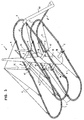
- the suspended runway according to this invention is shown in its whole in Figure 1 , showing a first example of its several possible embodiments, and in this case an embodiment intended to be used as a game.
- the supporting structure which is designated in its whole by reference 1
- the supporting structure is limited to a central region of the runway, and in this case it comprises a single pillar.
- the supporting structure could be foreseen two or more pillars, however always limited in their whole to a central region of the runway, whereby they could also be considered as separate portions of a single pillar.
- the track line structure forming the proper runway includes some track sections 2 which are directly sustained by the supporting structure 1, but it is a characteristic feature of the invention that the track line structure also includes several track sections 3 which project, overhanging for a large extension, out of the supporting structure 1. These track sections 3, which cannot be sustained directly by the supporting structure 1 because they are located outside the same, are sustained by the supporting structure by means of cables 4, which form rigging systems connected, at a first end, to the supporting structure and, at the opposite end, to the overhanging track sections 3.
- the supporting structure 1 forming a pillar is, in this case, a reticular structure including columns and cross bars, which structure, though occupying in plan a reduced space, may have a great resistance and stability. It directly supports the track sections 2, which in this case are connected at both ends to the supporting structure 1, whereas a great part of the runway is formed by groups of track sections 3 which project in an important way, overhanging at both opposite sides of the supporting structure 1.
- the groups of overhanging track sections 3 comprise in general rectilinear track sections directed outwards and towards the supporting structure 1, and curvilinear track sections which connect together said rectilinear track sections.
- the runway initiates from a upper start track section 2' and ends for example with a lower arrival track section 3', which in this case is ascending in order to slow down and stop the vehicles.
- the passage of the vehicles between non-suspended track sections 2 and suspended track sections 3 may advantageously take place through hollow elements of the supporting structure 1.
- the runway follows a substantially helicoidal path with oval plane. This kind of trajectory is preferable for technical and practical reasons, however it is not exclusive because, by resolving some problems posed by non-oval paths, the user can also chose different trajectories.
- All the overhanging track sections 3, which cannot be directly sustained by the supporting structure 1, are supported therefrom by means of cables 4, which may preferably be regulated, and form a rigging system, being fixed at one end to the track sections 3 to be sustained and at the opposite end to the supporting structure 1.
- the regulation of the length of cables 4 allows regulating both the position and the slope of the track sections 3 and, as a consequence, the travel conditions of the vehicles driven by gravity, in order to attain both their stability on the runway and the desired travel mode.
- the runway when embodied for the use as a game, is advantageously composed by a system of composable elements which will be described later on. It is to be remarked that this allows those who build the suspended runway to give to it extremely variable and modifiable shapes and trajectories, and this ensures the development of a very useful practical experience, in addition to the need of reasoning on the design. It is thus possible to commence the construction with relatively simple structures, and to confront more complex structures after development of a sufficient experience. This ensures a very formative effect of the game.
- Figure 2 shows a second example of suspended runway to be used as a game, which can be realized by means of the system of composable elements according to the invention.
- the difference of this runway with respect to that according to Figure 1 mainly resides in that the track sections 2 directly connected to the supporting structure 1 are hooked thereto near their own central region, rather than to be connected to the supporting structure at both their own end portions. In this way, the track line structure becomes external in an about complete manner with respect to the supporting structure.
- the runway ends with an extended horizontal track section 3' intended to be traveled by inertia.
- Figure 3 represents in a very diagrammatic manner an example of a suspended runway according to the invention, which in this case has the character of a runway intended to be traveled by passengers carrying vehicles.
- the supporting structure 1 of this example is not made by composable elements. It includes a central vertical mast 1A from which depart horizontal extensions 1 B; to these extensions are directly connected the track sections 2, and from them extend upwards or downwards some uprights 1C to which are connected the rigging systems sustaining the overhanging track sections 3.
- a lifting device 43 for lifting the vehicles from the lower arrival track section 3' to the upper start track section 2'.
- the remaining of the structure may substantially correspond to that has been formerly described, except, of course, its embodiment in a larger size and with shapes suitable for the travel of passengers carrying vehicles.
- the structure is of a substantially conventional kind, and it comprises a number of props 5, forming in their whole a complex and extended supporting structure, directly sustaining rectilinear and curvilinear track sections 6, departing from a upper start track section 6' and ending to a lower final track section 6".
- the system of composable elements specifically intended for the realization of suspended runway structures, and incidentally also for the realization of non-suspended runways be compatible and integrated with the general system for the composition of static and dynamic structures described in the European Patent No. 1.022.040 .
- That system is mainly characterized by female tubular coupling members whose walls are defined in cross section by eight circle arcs symmetrically subsequent with respect to the center of the coupling member. Therefore, this particular structure of the female coupling members is maintained in the elements described here, specifically intended for the realization of supporting structures for runways, and all the elements are provided with features and shapes compatible with this structure of said female coupling members.
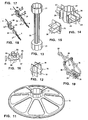
- the main elements specifically intended for the realization of runway structures are described in the following.
- Figure 5 shows a rectilinear track line section 7, seen from bottom. It has the character of a track section, comprising a pair of rectilinear bars 8 mutually connected at intervals by curved ties 9, whose concavity faces the side of the track intended to be traveled. At each end of the track section there is provided a coupling tie 10 having at bottom two teeth 11 described later on. Moreover there are provided at bottom some projections 9', whose purpose is that of stabilizing the longitudinal position of the track section when it is sustained by the supporting structure only in the central region, as in the embodiment of Figure 2 , or anyway in a single region, and not at both ends thereof as in Figure 1 . Preferably, as shown by Figure 5 , there are provided several pairs of said lower projections 9'.
- the reason of this multiplicity is that, in the realization of the runway, the builder may decide to impart to certain track sections a slope considerably different from the slope of other track sections. In this case the correct position of the various track sections may be impaired, and then it should be restored. This is obtained by suitably modifying the position where some track sections are fixed to the supporting structure.
- the multiplicity of the lower centering projections 9' ensures the possibility of easily effecting such modifications, which may be required to be different from case to case.
- Figure 6 represents in a similar way a curvilinear track line section 12, which differs from the rectilinear track line section 7 only in that the bars 13 forming the track section are concentrically curved instead of being rectilinear.
- the curve extends for 90°, however also different angular extensions of the curved sections may be chosen.
- the ties 9 and the end coupling ties 10 are identical to those already described of the rectilinear track line section 7.
- Figure 7 represents a coupling element 14 serving for the mutual connection, in any combination, of track sections 7 and 12. It has a wide-H cross section wherein can accommodate a coupling tie 10, and it has two pairs of transverse slots 15 suitable for engaging with the teeth 11 of the coupling ties 10.
- the connection between two rectilinear track sections 7 (or, in the same manner, between two curvilinear track sections 12 or else between mixed track sections 7 and 12) by means of the coupling element 14 is effected as shown by Figures 8 and 9 .
- One of the teeth 11 of each track section is engaged in a slot 15 of the coupling element 14, both said parts being aligned in plan but forming an angle in elevation ( Figure 8 ).
- the track sections 7 and 12 are formed of a semi-rigid plastic material which allows a limited curvature of the track section around a transversal axis parallel to the travel plane of the track as well as a limited torsion of the same along a longitudinal axis, but no noticeable deformation of the track section in the transverse direction. This allows to arrange the track line along the desired trajectory, however without compromising the possibility of correct travel of the vehicles on the track line.
- Figure 11 shows a base element for the supporting structure of the runway.
- This element includes a rest portion 16, which in this example has the shape of a spoked wheel, and a central sleeve 17 whose cross section comprises eight circle arcs symmetrically subsequent with respect to the center of the element, surrounding a cavity, like the already described cross section of a tubular female coupling member of the element system for the composition of static and dynamic constructions as described in the European Patent No. 1.022.040 .
- Said cross section is maintained in all the female coupling members, in the present system of composable elements too.
- Figure 12 shows a coupling element for the supporting structure, which is intended to allow the mutual connection between two female coupling members. It comprises a thin plate 18 having the same outline of a female coupling member and, projecting from both faces of this plate, plane surfaces 19 having six edges suitable for being frictionally inserted, according to two orthogonal directions, into six of the eight arcs of a female coupling member.
- Figure 13 shows an element whose length is multiple of a module, formed by a trunk 20 having at both ends female coupling members 21. These elements may advantageously be provided in different lengths, all multiple of a module, in order to realize, using a reduced number of elements, the columns and the cross bars of the supporting structure, in the desired measures.
- Figure 14 shows a multiple connection element, so-called knot, which is formed by a tubular portion 22 having the profile of a female coupling member, from whose opposite sides project male coupling surfaces 23 corresponding to the already described surfaces 19.
- the knot is also provided with engagement means 24 for one or two additional elements, one of which is represented in Figure 15 . It comprises a plate 25 suitable for engaging said engagement means 24, and male coupling surfaces 26 corresponding to the male coupling surfaces 23. This additional element allows increasing the number of directions according to which the knot may exert its activity.
- the tubular portion 22 of the knot has a through cavity, and therefore it is particularly suitable for being traversed by a track section 7 or 12 and for supporting the same.
- Figure 16 shows a connection element for the supporting structure, intended to allow the mutual connection between two female coupling members and moreover to allow hooking a cable which supports overhanging elements. It comprises a thin plate 27 having an outline like that of a female coupling member, and projecting from both sides of said plate four cylindrical sleeves 28 suitable for being frictionally inserted into four of the eight arcs of a female coupling member. Moreover, from the peripheral edges of said plate 27 project hooks 29 suitable for receiving a noose formed by a suspension cable 4. These elements serve for providing on the supporting structure some fixing points for the rigging system which sustains the overhanging track sections.
- Figures 17 and 18 illustrate an element which forms a device intended to regulate the extension of a suspension cable. It is shown in Figure 17 open for the insertion of a cable, and in Figure 18 closed in operative position.
- This element comprises a pair of clamps 30 and 31, mutually connected in steps and suitable for being snap closed, as well as a hook 32 also serving as a control handle.
- a cable 4 ( Figure 17 ) is inserted in the first clamp 30, is brought in correspondence of the second clamp 31 and is inserted therein. From here the cable extends up to a suspension member (for example, to a hook 39 of an element according to Figure 19 , described later on) and it returns therefrom by forming a ring 4', which is engaged in the hook 32.
- the hook 32 used as a handle, renders easy this maneuver, without incurring in resistance and allowing the person to turn the attention to the effects produced by the regulation in course of execution on the position and slope assumed by the track elements sustained by the cable, in order that they can be disposed in the desired position.
- Some walls 30' are advantageously provided, forming guide surfaces facilitating the correct engagement of the cable into the clamps.
- Figure 19 shows a coupling element between two track sections, which in addition allows fixing a suspension cable without hindering the travel on the track section.
- This element includes a coupling element 34, which is in part identical to the already described coupling element 14, and like that is provided with two pairs of transverse slots 35 for hooking the track sections, but it differs from the former in that from its sides project two uprights 36, which in this case are triangular, at the ends whereof a pivot 37 connects a movable element 38 by allowing its rotation.
- the movable element 38 ends with a hook 39 to which can be fixed an end noose of a suspension cable 4.
- the space left free by the uprights 36 and the pivot 37 over the coupling element 34 is designed sufficient for allowing the travel of a vehicle on the track section sustained by the coupling element 34.
- the orientability of the movable element 38 ensures that it spontaneously arranges itself along the pull direction of the cable connected to it.
- the element according to Figure 19 allows therefore to mutually connect two track sections 7 or 12 and to join at the connection point one end of a suspension cable 4, whose opposite end is connected to the supporting structure 1, for example by means of an element 27-29 according to Figure 16 .
- composable modular elements described allow therefore to realize suspended runways as for example those shown in Figures 1 and 2 , as well as, by omitting the elements purporting to the rigging systems, a non-suspended runway such as for example that shown in Figure 4 . Since the described elements are designed in such a way as to be compatible and integrated with the system of composable elements according to the European Patent No. 1,022,040 , also the elements of that system may be used along with the described elements, thus extending, practically without limits, the possibility of realizations offered by a thus integrated element system.
- this invention is not limited to the embodiments described and shown by way of examples. Several modifications are possible for those skilled in the art, especially in the design of the composable modular elements and in the realization of additional elements, suitable for integrating the system. For example, it is possible to provide special stations for housing or receiving the vehicles both in the start station and in the arrival station, and lifting means can be provided for returning the vehicles from the arrival station to the start station.
- the vehicles intended to travel on the runway will be mainly driven by gravity, but this does not exclude the possible provision of some auxiliary driving means.
Landscapes
- Toys (AREA)
- Road Paving Structures (AREA)
- Road Signs Or Road Markings (AREA)
- Sorption Type Refrigeration Machines (AREA)
- Eye Examination Apparatus (AREA)
- Lift-Guide Devices, And Elevator Ropes And Cables (AREA)
- Prostheses (AREA)
- Vehicle Step Arrangements And Article Storage (AREA)
- Pinball Game Machines (AREA)
Claims (23)
- Hängebahn, die von nur oder hauptsächlich durch Schwerkfraft betriebenen Fahrzeugen befahrbar ist, insgesamt ein Stützgerüst (1) und ein eine durch das Stützgerüst (1) abgestütze Hängebahn bildendes Gleisgerüst (2,3) umfasst, und sich von einem oberen Abfahrtsbereich (2') bis zu einem unteren Einfahrbereich (3') erstreckt, wobei diese Bereiche (2',3') durch direkt mit dem Stützgerüst (1) verbundene Gleisabschnitte gebildet sind, in der Hängebahn das Stützgerüst (1) auf einen mittleren Bereich der gesamten Hängebahn beschränkt ist, wobei das Gleisgerüst (2,3) einige direkt mit dem Stützgerüst (1) verbundene Abschnitte (2) und einige fliegend angeordnete Abschnitte (3) mit beträchtlichem Umfang umfasst, die sich ausserhalb des Stützgerüstes (1) erstrecken, und wobei diese fliegend angeordnete Abschnitte (3) des Gleisgerüstes über Seilbahnsysteme (4) mit dem Stützgerüst (1) verbunden sind, die die fliegend angeordneten Abschnitte (3) des Gleisgerüstes abstützen und ihre geometrische Lage bestimmen, dadurch gekennzeichnet, dass die die fliegend angeordneten Abschnitte (3) abstützenden Seilbahnsysteme (4) aus Kabeln (4) bestehen, deren Spannung regelbar ist.
- Hängebahn nach Anspruch 1, dadurch gekennzeichnet, dass das mittlere Stützgerüst (1) im wesentlichen aus einem Mast besteht.
- Hängebahn nach Anspruch 2, dadurch gekennzeichnet, dass der das Stützgerüst (1) bildende Mast lediglich aus einem eigentlichen, im wesentlichen senkrechten Mast (1A) besteht, der mit im wesentlichen waagerechten Auslegern (1 B) versehen ist, die die Gleisabschnitte (2) halten und mit denen die Seilbahnsysteme, eventuell über Ständer (3C), verbunden sind.
- Hängebahn nach Anspruch 1, dadurch gekennzeichnet, dass die durch das Gleisgerüst (2,3) bestimmte Hängebahn im wesentlichen wendelförmig verläuft und ovalen Grundriss hat.
- Hängebahn nach Anspruch 1, die als Spielzeug zum Einsatz kommen soll, dadurch gekennzeichnet, dass sowohl das Stützgerüst (1) als auch das Gleisgerüst (2,3) aus mehreren nach dem Baukastensystem zusammengesetzten einheitlichen Elementen hergestellt sind.
- Hängebahn nach Anspruch 5, dadurch gekennzeichnet, dass sich mit den einheitlichen Elementen dieses Baukastensystems auch einfache Hängebahngerüste herstellen lassen, bei welchen sämtliche Elemente (6) des Gleisgerüstes direkt durch das Stützgerüst (5) getragen sind und nicht über Seilbahnsysteme aufgehängt sind.
- Hängebahn nach Anspruch 5, dadurch gekennzeichnet, dass das aus einheitlichen Elementen bestehende, insbesondere zur Ausführung des Stützgerüstes (1) und des Gleisgerüstes (2,3) der Hängebahn bestimmte Baukastensystem mit einem allgemeinen Baukastensystem zur Herstellung von statischen und dynamischen Tragwerken vereinbar ist und sich in dasselbe eingliedern lässt.
- Hängebahn nach Anspruch 7, dadurch gekennzeichnet, dass es sich beim allgemeinen Baukastensystem zur Herstellung von statischen und dynamischen Tragwerken, mit dem sich das insbesondere zur Ausführung des Stützgerüstes (1) und des Gleisgerüstes (2,3) der Hängebahn bestimmte Baukastensystem vereinbaren und eingliedern lässt, um das Baukastensystem nach dem europäischen Patent Nr. 1.022.040 handelt.
- Hängebahn nach einem oder mehreren der Ansprüche 5 bis 8, dadurch gekennzeichnet, dass dieselbe Elemente zur Bildung eines Gleisabschnittes (7;12) umfasst, der aus einem Paar gerader oder kurvenlinearer Stangen (8;13) besteht, die stellenweise durch bogenförmige Schwellen (9) miteinander verbunden sind, deren Konkavität der befahrbaren Seite des Gleisabschnittes (7;12) zugekehrt ist, wobei die Enden des Stangenpaares (8;13) jeweils einen Anschlussteg (10) aufweisen, dessen Unterseite mit zwei Verbindungszähnen (11) versehen ist.
- Hängebahn nach Anspruch 9, dadurch gekennzeichnet, dass die Unterseite des Gleisabschnittes (7;12) Erhebungen (9') aufweist, die zur Stabilisierung der Lage in Längsrichtung dienen.
- Hängebahn nach Anspruch 9, dadurch gekennzeichnet, dass der Gleisabschnitt aus einem halbsteifen Kunststoff hergestellt ist, der eine beschränkte Krümmung des Gleisabschnittes (7;12) gemäss einer parallel zur Lauffläche des Gleisabschnittes verlaufenden Achse sowie auch eine beschränkte Verdrehung des Gleisabschnittes, jedoch keine wesentliche Verformung in Querrichtung, zulässt.
- Hängebahn nach Anspruch 9, dadurch gekennzeichnet, dass dieselbe einen Kupplungsteil (14) für Gleisabschnitte umfasst, der einen Querschnitt mit der Form eines breiten H, in dem ein Anschlussteg (10) Platz nehmen kann, und zwei Paar Querschlitze (15) aufweist, in die die Verbindungszähne (11) der Anschlusstege (10) eingreifen können.
- Hängebahn nach einem oder mehreren der Ansprüche 5 bis 8, dadurch gekennzeichnet, dass das Stützgerüst (1) ein Kupplungselement (21) in Form einer rohrförmigen Aufnahme aufweist, in deren Querschnitt acht Kreisbogen symmetrisch zur Mitte des Kupplungselements aufeinanderfolgen.
- Hängebahn nach Anspruch 9 und 13, dadurch gekennzeichnet, dass ein Element (21) zur Zusammensetzung eines Gleisgerüstes und ein Element (7;12) zur Zusammensetzung eines Stützgerüstes (1) so aufeinander abgestimmt sind, dass der Gleisabschnitt (7;12) in den Hohlraum des Kupplungselements (21) elastisch einrasten und dort befestigt werden kann, wobei beide Stangen (8;13) des Gleisabschnittes in zwei nicht unmittelbar aufeinanderfolgende Kreisbogen des Querschnittes des Kupplungselements (21) eingreifen.
- Hängebahn nach Anspruch 13, dadurch gekennzeichnet, dass ein Grundelement (16,17) für ein Stützgerüst (1) eine Auflage (16), eventuell in Form eines Speichenrades, und eine mittige Hülse (17) umfasst, deren Querschnitt dem Querschnitt eines eine rohrförmige Aufnahme bildenden weiblichen Kupplungselements (21) entspricht.
- Hängebahn nach Anspruch 13, dadurch gekennzeichnet, dass dieselbe wenigstens einen Kupplungsteil (18,19) für ein Stützgerüst (1) umfasst, der die Kupplung zwischen zwei aus rohrförmigen weiblichen Aufnahmen (21) bestehenden Kupplungselementen ermöglichen soll, eine dünne Platte (18), die das gleiche Aussenprofil eines als rohrförmige weiblichen Aufnahme (21) ausgebildeten Kupplungselementes hat, und Planflächen (19) aufweist, die jeweils aus einer der beiden Seiten der Platte vorspringen und sechs Ränder haben, die in sechs der acht Kreisbogen eines als rohrförmige Aufnahme ausgebildeten weiblichen Kupplungselementes (21) nach zwei rechtwinkligen Richtungen reibschlüssig eingreifen können.
- Hängebahn nach Anspruch 13, dadurch gekennzeichnet, dass dieselbe ein Element (20,21) umfasst, das die mehrfache Länge eines einheitlichen Bauelements für ein Stützgerüst (1) hat, aus einem Abschnitt (20) besteht, der an beiden Enden mit als rohrförmige Aufnahmen ausgebildeten weiblichen Kupplungselementen (21) versehen ist und zur Bildung von Säulen oder Querträgern verwendet werden kann.
- Hängebahn nach Anspruch 13, dadurch gekennzeichnet, dass dieselbe ein mehrfaches Anschlusselement für ein Stützgerüst (1) aufweist, und zwar einen sogenannten Knoten (22,23), der aus einem rohrförmigen Teil (22) besteht, der das Profil eines aus einer rohrförmigen Aufnahme bestehenden weiblichen Kupplugselement hat und aus dessen beiden entgegengesetzten Seiten männlichen Planflächen (23) zur Steckverbindung ausgehen, die sechs Ränder haben, die in sechs der acht Kreisbogen eines als rohrförmige Aufnahme ausgebildeten weiblichen Kupplungselementes (21) nach zwei rechtwinkligen Richtungen reibschlüssig eingreifen können.
- Hängebahn nach Anspruch 18, dadurch gekennzeichnet, dass dieselbe ein mehrfaches Anschlusselement (22,23) umfasst, das Steckmittel (24) für ein oder zwei zusätzliche Elemente (25,26) aufweist, die jeweils eine Platte (25) haben, in die die Steckmittel (24) eingreifen können, wobei aus der Platte (25) männliche Planflächen (26) zur Steckverbindung vorspringen, die sechs Ränder haben, die in sechs der acht Kreisbogen eines als rohrförmige Aufnahme ausgebildeten weiblichen Kupplungselementes (21) nach zwei rechtwinkligen Richtungen reibschlüssig eingreifen können.
- Hängebahn nach Anspruch 18, dadurch gekennzeichnet, dass dieselbe ein mehrfaches Anschlusselement (22,23) umfasst, wobei durch den Durchgangshohlraum des rohrförmigen Teils (22) desselben ein Gleisabschnitt (7,12) durchgehen kann, der durch den rohrförmigen Teil getragen wird.
- Hängebahn nach Anspruch 13, dadurch gekennzeichnet, dass dieselbe ein Anschlusselement (27,29) für ein Stützgerüst (1) umfasst, wobei dieses Element aus einer dünnen Platte (27) mit dem Aussenprofil eines aufnahmeförmigen weiblichen Kupplungselementes (21) besteht und an jeder der beiden Seiten der Platte (27) vier zylinderförmige Hülsen (22) angeordnet sind, die in vier der acht Kreisbogen eines aufnahmeförmigen weiblichen Kupplungselementes (21) reibschlüsssig eingesteckt werden können, und aus den Umfangsrändern der Platte (27) Haken (29) vorspringen, die eine Endschlinge eines Kabels (4) zur Halterung von fliegend angeordneten Hängebahnabschnitten (3) aufnehmen können.
- Hängebahn nach Anspruch 1, dadurch gekennzeichnet, dass dieselbe ein Element (30-32) zur Regelung der Erstreckung eines zu einem Seilbahnsystem gehörenden Kabels (4) umfasst, das ein Paar stufenartig miteinander verbundener und zuschnappender Spannbacken (30,31) aufweist, die dazu bestimmt sind, dem Aufhängekabel (4) eine selbstsperrende Eigenschaft zu verleihen und dennoch die gesteuerte Verschiebung dieses Elements (30-32) am Kabel (4) zu gestatten, wobei das Element (30-32) ausserdem einen Haken (32), der auch als Bedienungshandhabe dient, sowie Führungsflächen (30') besitzt, die das richtige Einführen des Kabels (4) erleichtern.
- Hängebahn nach Anspruch 12, dadurch gekennzeichnet, dass dieselbe ein Anschlusselement (34) umfasst, aus dessen Seiten zwei Ständer (36) ragen, wobei sich ein an deren Enden vorgesehener Zapfen (37) an ein bewegliches Element (38) anschliesst, das mit einem Haken zur Aufnahme der Verbindung eines Aufhängungskabels (4) endet.
Applications Claiming Priority (3)
| Application Number | Priority Date | Filing Date | Title |
|---|---|---|---|
| IT2001TO000883A ITTO20010883A1 (it) | 2001-09-18 | 2001-09-18 | Pista sospesa. |
| ITTO20010883 | 2001-09-18 | ||
| PCT/EP2002/000636 WO2003031009A1 (en) | 2001-09-18 | 2002-01-22 | Suspended runway |
Publications (2)
| Publication Number | Publication Date |
|---|---|
| EP1427498A1 EP1427498A1 (de) | 2004-06-16 |
| EP1427498B1 true EP1427498B1 (de) | 2008-12-17 |
Family
ID=11459198
Family Applications (1)
| Application Number | Title | Priority Date | Filing Date |
|---|---|---|---|
| EP02726102A Expired - Lifetime EP1427498B1 (de) | 2001-09-18 | 2002-01-22 | Hängelaufbahn |
Country Status (9)
| Country | Link |
|---|---|
| US (2) | US6945839B2 (de) |
| EP (1) | EP1427498B1 (de) |
| JP (1) | JP2005504615A (de) |
| CN (1) | CN100420500C (de) |
| AT (1) | ATE417658T1 (de) |
| DE (1) | DE60230426D1 (de) |
| IT (1) | ITTO20010883A1 (de) |
| WO (1) | WO2003031009A1 (de) |
| YU (1) | YU49103A (de) |
Families Citing this family (34)
| Publication number | Priority date | Publication date | Assignee | Title |
|---|---|---|---|---|
| ITTO20030007U1 (it) * | 2003-01-17 | 2004-07-18 | Quercetti Alessandro & Co | Elemento per la composizione di una pista di scorrimento di palline del tipo a caduta. |
| RU2292226C2 (ru) * | 2003-07-10 | 2007-01-27 | Владимир Алексеевич Гнездилов | Способ изготовления и монтажа направляющего пути (варианты), секция направляющего пути (варианты) |
| US20050191939A1 (en) * | 2004-01-23 | 2005-09-01 | Sheltman David A. | Scaffold support for toy vehicle trackset |
| GB2410701A (en) * | 2004-02-05 | 2005-08-10 | Heavens Above | Toy track system |
| WO2007131207A2 (en) | 2006-05-04 | 2007-11-15 | Mattel, Inc. | Wheeled toy vehicles and playsets for use therewith |
| EP1972365A3 (de) * | 2007-03-22 | 2011-01-12 | Innova Patent GmbH | Anlage zur Beförderung von Personen |
| US7882788B2 (en) * | 2007-10-01 | 2011-02-08 | Carl Sorenson | Rail system for spherical objects |
| RU2012112954A (ru) | 2009-09-04 | 2013-10-10 | Уилльям Дж. КИТЧЕН | Неподвижный трек с аттракционом для катания с карданно подвешенными пассажирскими кабинками |
| US8066545B2 (en) | 2009-10-07 | 2011-11-29 | Mattel, Inc. | Toy vehicle track play set |
| ES2556902T3 (es) * | 2010-07-16 | 2016-01-20 | Marc Keersmaekers | Andamio con elementos de andamio y métodos para montaje de los mismos |
| US8608527B2 (en) | 2010-08-27 | 2013-12-17 | Mattel, Inc. | Wall mounted toy track set |
| BR112013030187A2 (pt) | 2011-05-26 | 2018-04-24 | J Kitchen William | pista para torre |
| US9452366B2 (en) | 2012-04-27 | 2016-09-27 | Mattel, Inc. | Toy track set |
| US9457284B2 (en) | 2012-05-21 | 2016-10-04 | Mattel, Inc. | Spiral toy track set |
| CN102750869B (zh) * | 2012-06-21 | 2016-04-27 | 中国核工业二三建设有限公司 | 核电施工模型 |
| USD712491S1 (en) | 2012-06-30 | 2014-09-02 | Cepia Llc | Ball track set |
| EP2708269A1 (de) | 2012-09-12 | 2014-03-19 | Mattel, Inc. | Wandmontierter Spielzeugschienensatz |
| EP2716339A1 (de) | 2012-10-04 | 2014-04-09 | Mattel, Inc. | Wandmontierter Spielzeugschienensatz |
| USD702775S1 (en) | 2013-01-02 | 2014-04-15 | Cepia, Llc | Ball track set |
| CN105744994B (zh) * | 2013-11-17 | 2019-01-01 | W·J·基钦 | 用于塔架式乘坐设施的轨道和驱动装置 |
| KR101624832B1 (ko) | 2015-01-28 | 2016-05-27 | 권성태 | 볼 레일이 구성된 블록 도미노 교육완구 |
| USD759774S1 (en) * | 2015-03-05 | 2016-06-21 | William J. Kitchen | Tracks for amusement rides |
| JP6219869B2 (ja) * | 2015-03-25 | 2017-10-25 | 株式会社ベンカン | 組立玩具 |
| USD806263S1 (en) | 2016-06-10 | 2017-12-26 | William J. Kitchen | Tracks for an observation tower |
| US9956493B1 (en) * | 2017-05-12 | 2018-05-01 | Sparkling Sky International Limited | Slide construction assemblies |
| US10653970B2 (en) * | 2017-06-30 | 2020-05-19 | Global Family Brands, LLC | User controllable marble run kit |
| USD928888S1 (en) * | 2018-01-17 | 2021-08-24 | Ravensburger Ag | Toy constructor piece |
| US11951411B2 (en) * | 2019-09-30 | 2024-04-09 | Pike Brands Llc | Marble actuated turntable |
| GB2591437A (en) * | 2019-11-06 | 2021-08-04 | Alan Calvert Stephen | Light transport transit pack |
| US11547949B2 (en) * | 2020-11-19 | 2023-01-10 | Makeway Ltd | Universal modular marble course system |
| US11413553B1 (en) * | 2021-02-08 | 2022-08-16 | Marcio Sequeira De Oliveira | Structural parts kit for formation of architectural and structural didactic models |
| USD1048463S1 (en) | 2021-03-12 | 2024-10-22 | Martin & Vleminckx Ltd. | Tower with viewing carriage tracks |
| US11779853B2 (en) * | 2021-10-19 | 2023-10-10 | Pike Brands Llc | Marble track connection system |
| CN219043091U (zh) * | 2022-12-23 | 2023-05-19 | 深圳市杰扬创昕科技有限公司 | 一种拼接类轨道组合玩具 |
Family Cites Families (34)
| Publication number | Priority date | Publication date | Assignee | Title |
|---|---|---|---|---|
| US399105A (en) * | 1889-03-05 | Trussed suspension-bridge | ||
| US293853A (en) * | 1884-02-19 | Portable railway | ||
| US629935A (en) * | 1898-07-11 | 1899-08-01 | Nelson H Sturgis | Suspension-bridge. |
| US812595A (en) * | 1905-11-01 | 1906-02-13 | Otis Roberts | Amusement apparatus. |
| US951874A (en) * | 1909-01-13 | 1910-03-15 | William Alexander Wood | Suspension-bridge. |
| US2000808A (en) * | 1934-07-20 | 1935-05-07 | Frederick V Williams | Toy |
| US2016191A (en) * | 1934-07-30 | 1935-10-01 | Cordova Joaquin Pedrero | Sectional cable suspension assembly |
| US2217593A (en) * | 1939-06-29 | 1940-10-08 | Robinson & Steinman | Bracing for suspension bridges |
| US2266549A (en) * | 1939-07-01 | 1941-12-16 | Robert Forgan | Suspension bridge |
| DE809398C (de) | 1948-10-02 | 1951-07-30 | Johann Hoefler | Schraubenfoermige Bahn fuer Spielfahrzeuge |
| US3132441A (en) * | 1961-11-24 | 1964-05-12 | Kenneth Roberts | Parallel spaced hoops forming a ball runway connected by resilient clips |
| US3587190A (en) * | 1968-09-27 | 1971-06-28 | Wesley W Ashton | Toy having flexible track |
| GB1296075A (de) * | 1969-02-13 | 1972-11-15 | ||
| US3605153A (en) * | 1970-03-10 | 1971-09-20 | Dominick George Constantino | Single tower suspension bridges |
| JPS4730551Y1 (de) * | 1970-08-13 | 1972-09-12 | ||
| US3953980A (en) * | 1975-01-13 | 1976-05-04 | Floyd William Bennett | Dock structure |
| DE2658485A1 (de) * | 1976-12-23 | 1978-06-29 | Rolf Eisenburg | Laufbahn fuer ein bahngebundenes spielzeug |
| GB2139909B (en) * | 1983-05-16 | 1986-07-23 | Hornby Hobbies | Toy railway track |
| GB8406962D0 (en) * | 1984-03-16 | 1984-04-18 | Cenefocus Ltd | Manually portable and temporary track section |
| US4898326A (en) * | 1987-10-28 | 1990-02-06 | Kadee Metal Products Co. | Track joining system |
| US4953785A (en) * | 1988-08-29 | 1990-09-04 | Hasbro, Inc. | Track assembly for toy vehicle |
| US5211366A (en) * | 1991-01-03 | 1993-05-18 | Cummings John W | Ornamental support for Christmas tree and the like |
| US5299735A (en) * | 1993-05-24 | 1994-04-05 | Thomas Herbert Y | Track-bed system for model railroad |
| US5690278A (en) * | 1996-01-16 | 1997-11-25 | Life-Like Products, Inc. | Track systems for model railroads |
| CN2275893Y (zh) * | 1996-06-24 | 1998-03-11 | 王立伟 | 飞旋桥 |
| US5678489A (en) * | 1996-07-08 | 1997-10-21 | Studio Eluceo Ltd. | Electrically-operated moving body travelling on a rail capable of explaining free quadrants described in the mobius theorem |
| US6074269A (en) * | 1996-09-24 | 2000-06-13 | Choas, L.L.C. | Kinetic toy |
| US5709581A (en) * | 1996-09-24 | 1998-01-20 | Chaos, L.L.C. | Kinetic toy |
| US5785573A (en) * | 1996-09-24 | 1998-07-28 | Chaos, L.L.C. | Kinetic toy |
| US5979783A (en) * | 1997-10-20 | 1999-11-09 | Learning Curve International, Inc. | Toy vehicle track coupling support |
| CN2342857Y (zh) * | 1997-12-16 | 1999-10-13 | 大洋玩具工业股份有限公司 | 以悬荡方式移动的游乐玩具 |
| US6170754B1 (en) | 1998-02-10 | 2001-01-09 | Mattel, Inc. | Spiral ramp for toy vehicles |
| US6155177A (en) * | 1998-07-13 | 2000-12-05 | Backfisch; Peter | Model train system with improved banking characteristics |
| IT1306995B1 (it) | 1999-01-20 | 2001-10-11 | Quercetti Alessandro & Co | Sistema di elementi per la composizione di costruzioni statiche odinamiche. |
-
2001
- 2001-09-18 IT IT2001TO000883A patent/ITTO20010883A1/it unknown
-
2002
- 2002-01-22 WO PCT/EP2002/000636 patent/WO2003031009A1/en not_active Ceased
- 2002-01-22 AT AT02726102T patent/ATE417658T1/de not_active IP Right Cessation
- 2002-01-22 YU YU49103A patent/YU49103A/sh unknown
- 2002-01-22 CN CNB028182375A patent/CN100420500C/zh not_active Expired - Fee Related
- 2002-01-22 US US10/051,179 patent/US6945839B2/en not_active Expired - Fee Related
- 2002-01-22 JP JP2003534036A patent/JP2005504615A/ja not_active Withdrawn
- 2002-01-22 DE DE60230426T patent/DE60230426D1/de not_active Expired - Fee Related
- 2002-01-22 EP EP02726102A patent/EP1427498B1/de not_active Expired - Lifetime
-
2004
- 2004-05-05 US US10/838,188 patent/US6953377B2/en not_active Expired - Fee Related
Also Published As
| Publication number | Publication date |
|---|---|
| WO2003031009A1 (en) | 2003-04-17 |
| DE60230426D1 (de) | 2009-01-29 |
| US6953377B2 (en) | 2005-10-11 |
| US20040203316A1 (en) | 2004-10-14 |
| US20030054727A1 (en) | 2003-03-20 |
| JP2005504615A (ja) | 2005-02-17 |
| US6945839B2 (en) | 2005-09-20 |
| YU49103A (sh) | 2006-03-03 |
| EP1427498A1 (de) | 2004-06-16 |
| ITTO20010883A0 (it) | 2001-09-18 |
| ATE417658T1 (de) | 2009-01-15 |
| WO2003031009A8 (en) | 2004-04-01 |
| CN1555283A (zh) | 2004-12-15 |
| ITTO20010883A1 (it) | 2003-03-18 |
| CN100420500C (zh) | 2008-09-24 |
Similar Documents
| Publication | Publication Date | Title |
|---|---|---|
| EP1427498B1 (de) | Hängelaufbahn | |
| US6951497B1 (en) | Toy vehicle intersection with elevational adjustment | |
| JP4232938B2 (ja) | 玩具組立セット及びその車両 | |
| US6170754B1 (en) | Spiral ramp for toy vehicles | |
| CA1284030C (en) | Device for supporting tracks for travelling toys | |
| US5938498A (en) | Toy construction block system with interblock connectors for extended support structures | |
| US7051948B2 (en) | Flexible track for a toy vehicle | |
| EP1229974B1 (de) | Konstruktionsspielzeugset mit fahrzeug | |
| WO2012047513A1 (en) | Toy race track system | |
| JP4408370B2 (ja) | 遠隔操作玩具システム | |
| CN112969516B (zh) | 带有连接条和环的组装玩具 | |
| US20040082258A1 (en) | Adapter block apparatus for accomodating toy vehicles | |
| EP0766982A1 (de) | Zusammengesetzte Rutsche | |
| US2442526A (en) | Toy | |
| US5376037A (en) | Continuous beltway and track sections for forming the beltway and a method of using the same | |
| US6758144B2 (en) | Fun vehicle and bob, toboggan or roller coaster run for using the same | |
| HK1068503A (en) | Suspended runway | |
| US5766084A (en) | Swing apparatus incorporating safety features | |
| KR102479221B1 (ko) | 익스트림 라이더용 주행레일 및 주행레일을 따라 이동하는 익스트림 라이더 | |
| KR102575280B1 (ko) | 레포츠용 공중 페달링 이동유닛을 포함하는 시설물 | |
| JPH0346397U (de) | ||
| US20240091660A1 (en) | Toy track systems, toy track vehicles, and related methodologies | |
| CN218652855U (zh) | 一种儿童体能拓展游乐设备 | |
| JPH10314336A (ja) | 遊戯部材 | |
| KR200232879Y1 (ko) | 다단높이를 갖는 그네 |
Legal Events
| Date | Code | Title | Description |
|---|---|---|---|
| PUAI | Public reference made under article 153(3) epc to a published international application that has entered the european phase |
Free format text: ORIGINAL CODE: 0009012 |
|
| 17P | Request for examination filed |
Effective date: 20040316 |
|
| AK | Designated contracting states |
Kind code of ref document: A1 Designated state(s): AT BE CH CY DE DK ES FI FR GB GR IE IT LI LU MC NL PT SE TR |
|
| AX | Request for extension of the european patent |
Extension state: AL LT LV MK RO SI |
|
| 17Q | First examination report despatched |
Effective date: 20061110 |
|
| GRAP | Despatch of communication of intention to grant a patent |
Free format text: ORIGINAL CODE: EPIDOSNIGR1 |
|
| GRAS | Grant fee paid |
Free format text: ORIGINAL CODE: EPIDOSNIGR3 |
|
| GRAS | Grant fee paid |
Free format text: ORIGINAL CODE: EPIDOSNIGR3 |
|
| GRAA | (expected) grant |
Free format text: ORIGINAL CODE: 0009210 |
|
| AK | Designated contracting states |
Kind code of ref document: B1 Designated state(s): AT BE CH CY DE DK ES FI FR GB GR IE IT LI LU MC NL PT SE TR |
|
| REG | Reference to a national code |
Ref country code: GB Ref legal event code: FG4D |
|
| REG | Reference to a national code |
Ref country code: CH Ref legal event code: EP |
|
| REG | Reference to a national code |
Ref country code: IE Ref legal event code: FG4D |
|
| REF | Corresponds to: |
Ref document number: 60230426 Country of ref document: DE Date of ref document: 20090129 Kind code of ref document: P |
|
| PG25 | Lapsed in a contracting state [announced via postgrant information from national office to epo] |
Ref country code: FI Free format text: LAPSE BECAUSE OF FAILURE TO SUBMIT A TRANSLATION OF THE DESCRIPTION OR TO PAY THE FEE WITHIN THE PRESCRIBED TIME-LIMIT Effective date: 20081217 Ref country code: NL Free format text: LAPSE BECAUSE OF FAILURE TO SUBMIT A TRANSLATION OF THE DESCRIPTION OR TO PAY THE FEE WITHIN THE PRESCRIBED TIME-LIMIT Effective date: 20081217 |
|
| PGFP | Annual fee paid to national office [announced via postgrant information from national office to epo] |
Ref country code: DE Payment date: 20090226 Year of fee payment: 8 |
|
| NLV1 | Nl: lapsed or annulled due to failure to fulfill the requirements of art. 29p and 29m of the patents act | ||
| PGFP | Annual fee paid to national office [announced via postgrant information from national office to epo] |
Ref country code: GB Payment date: 20090127 Year of fee payment: 8 |
|
| PG25 | Lapsed in a contracting state [announced via postgrant information from national office to epo] |
Ref country code: BE Free format text: LAPSE BECAUSE OF FAILURE TO SUBMIT A TRANSLATION OF THE DESCRIPTION OR TO PAY THE FEE WITHIN THE PRESCRIBED TIME-LIMIT Effective date: 20081217 Ref country code: ES Free format text: LAPSE BECAUSE OF FAILURE TO SUBMIT A TRANSLATION OF THE DESCRIPTION OR TO PAY THE FEE WITHIN THE PRESCRIBED TIME-LIMIT Effective date: 20090328 |
|
| PG25 | Lapsed in a contracting state [announced via postgrant information from national office to epo] |
Ref country code: PT Free format text: LAPSE BECAUSE OF FAILURE TO SUBMIT A TRANSLATION OF THE DESCRIPTION OR TO PAY THE FEE WITHIN THE PRESCRIBED TIME-LIMIT Effective date: 20090518 Ref country code: MC Free format text: LAPSE BECAUSE OF NON-PAYMENT OF DUE FEES Effective date: 20090131 Ref country code: SE Free format text: LAPSE BECAUSE OF FAILURE TO SUBMIT A TRANSLATION OF THE DESCRIPTION OR TO PAY THE FEE WITHIN THE PRESCRIBED TIME-LIMIT Effective date: 20090317 Ref country code: AT Free format text: LAPSE BECAUSE OF FAILURE TO SUBMIT A TRANSLATION OF THE DESCRIPTION OR TO PAY THE FEE WITHIN THE PRESCRIBED TIME-LIMIT Effective date: 20081217 |
|
| REG | Reference to a national code |
Ref country code: CH Ref legal event code: PL |
|
| PLBE | No opposition filed within time limit |
Free format text: ORIGINAL CODE: 0009261 |
|
| STAA | Information on the status of an ep patent application or granted ep patent |
Free format text: STATUS: NO OPPOSITION FILED WITHIN TIME LIMIT |
|
| REG | Reference to a national code |
Ref country code: IE Ref legal event code: MM4A |
|
| PG25 | Lapsed in a contracting state [announced via postgrant information from national office to epo] |
Ref country code: LI Free format text: LAPSE BECAUSE OF NON-PAYMENT OF DUE FEES Effective date: 20090131 Ref country code: DK Free format text: LAPSE BECAUSE OF FAILURE TO SUBMIT A TRANSLATION OF THE DESCRIPTION OR TO PAY THE FEE WITHIN THE PRESCRIBED TIME-LIMIT Effective date: 20081217 Ref country code: CH Free format text: LAPSE BECAUSE OF NON-PAYMENT OF DUE FEES Effective date: 20090131 |
|
| PGFP | Annual fee paid to national office [announced via postgrant information from national office to epo] |
Ref country code: FR Payment date: 20090128 Year of fee payment: 8 |
|
| 26N | No opposition filed |
Effective date: 20090918 |
|
| PG25 | Lapsed in a contracting state [announced via postgrant information from national office to epo] |
Ref country code: IE Free format text: LAPSE BECAUSE OF NON-PAYMENT OF DUE FEES Effective date: 20090122 |
|
| GBPC | Gb: european patent ceased through non-payment of renewal fee |
Effective date: 20100122 |
|
| REG | Reference to a national code |
Ref country code: FR Ref legal event code: ST Effective date: 20100930 |
|
| PG25 | Lapsed in a contracting state [announced via postgrant information from national office to epo] |
Ref country code: FR Free format text: LAPSE BECAUSE OF NON-PAYMENT OF DUE FEES Effective date: 20100201 Ref country code: GR Free format text: LAPSE BECAUSE OF FAILURE TO SUBMIT A TRANSLATION OF THE DESCRIPTION OR TO PAY THE FEE WITHIN THE PRESCRIBED TIME-LIMIT Effective date: 20090318 |
|
| PG25 | Lapsed in a contracting state [announced via postgrant information from national office to epo] |
Ref country code: DE Free format text: LAPSE BECAUSE OF NON-PAYMENT OF DUE FEES Effective date: 20100803 |
|
| PG25 | Lapsed in a contracting state [announced via postgrant information from national office to epo] |
Ref country code: GB Free format text: LAPSE BECAUSE OF NON-PAYMENT OF DUE FEES Effective date: 20100122 |
|
| PG25 | Lapsed in a contracting state [announced via postgrant information from national office to epo] |
Ref country code: LU Free format text: LAPSE BECAUSE OF NON-PAYMENT OF DUE FEES Effective date: 20090122 |
|
| PGFP | Annual fee paid to national office [announced via postgrant information from national office to epo] |
Ref country code: IT Payment date: 20110111 Year of fee payment: 10 |
|
| PG25 | Lapsed in a contracting state [announced via postgrant information from national office to epo] |
Ref country code: TR Free format text: LAPSE BECAUSE OF FAILURE TO SUBMIT A TRANSLATION OF THE DESCRIPTION OR TO PAY THE FEE WITHIN THE PRESCRIBED TIME-LIMIT Effective date: 20081217 |
|
| PG25 | Lapsed in a contracting state [announced via postgrant information from national office to epo] |
Ref country code: CY Free format text: LAPSE BECAUSE OF FAILURE TO SUBMIT A TRANSLATION OF THE DESCRIPTION OR TO PAY THE FEE WITHIN THE PRESCRIBED TIME-LIMIT Effective date: 20081217 |
|
| PG25 | Lapsed in a contracting state [announced via postgrant information from national office to epo] |
Ref country code: IT Free format text: LAPSE BECAUSE OF NON-PAYMENT OF DUE FEES Effective date: 20120122 |