EP1426676A2 - Verfahren um eine optische Funktion in einem Komponenten einer Beleuchtungs- oder Signalvorrichtung eines Kraftfahrzeugs zu realisieren - Google Patents
Verfahren um eine optische Funktion in einem Komponenten einer Beleuchtungs- oder Signalvorrichtung eines Kraftfahrzeugs zu realisieren Download PDFInfo
- Publication number
- EP1426676A2 EP1426676A2 EP20030292977 EP03292977A EP1426676A2 EP 1426676 A2 EP1426676 A2 EP 1426676A2 EP 20030292977 EP20030292977 EP 20030292977 EP 03292977 A EP03292977 A EP 03292977A EP 1426676 A2 EP1426676 A2 EP 1426676A2
- Authority
- EP
- European Patent Office
- Prior art keywords
- component
- mask
- laser radiation
- laser
- metallized
- Prior art date
- Legal status (The legal status is an assumption and is not a legal conclusion. Google has not performed a legal analysis and makes no representation as to the accuracy of the status listed.)
- Withdrawn
Links
Images


Classifications
-
- B—PERFORMING OPERATIONS; TRANSPORTING
- B60—VEHICLES IN GENERAL
- B60Q—ARRANGEMENT OF SIGNALLING OR LIGHTING DEVICES, THE MOUNTING OR SUPPORTING THEREOF OR CIRCUITS THEREFOR, FOR VEHICLES IN GENERAL
- B60Q1/00—Arrangement of optical signalling or lighting devices, the mounting or supporting thereof or circuits therefor
- B60Q1/0029—Spatial arrangement
- B60Q1/0041—Spatial arrangement of several lamps in relation to each other
-
- F—MECHANICAL ENGINEERING; LIGHTING; HEATING; WEAPONS; BLASTING
- F21—LIGHTING
- F21S—NON-PORTABLE LIGHTING DEVICES; SYSTEMS THEREOF; VEHICLE LIGHTING DEVICES SPECIALLY ADAPTED FOR VEHICLE EXTERIORS
- F21S41/00—Illuminating devices specially adapted for vehicle exteriors, e.g. headlamps
- F21S41/30—Illuminating devices specially adapted for vehicle exteriors, e.g. headlamps characterised by reflectors
- F21S41/37—Illuminating devices specially adapted for vehicle exteriors, e.g. headlamps characterised by reflectors characterised by their material, surface treatment or coatings
-
- F—MECHANICAL ENGINEERING; LIGHTING; HEATING; WEAPONS; BLASTING
- F21—LIGHTING
- F21S—NON-PORTABLE LIGHTING DEVICES; SYSTEMS THEREOF; VEHICLE LIGHTING DEVICES SPECIALLY ADAPTED FOR VEHICLE EXTERIORS
- F21S43/00—Signalling devices specially adapted for vehicle exteriors, e.g. brake lamps, direction indicator lights or reversing lights
- F21S43/30—Signalling devices specially adapted for vehicle exteriors, e.g. brake lamps, direction indicator lights or reversing lights characterised by reflectors
- F21S43/33—Signalling devices specially adapted for vehicle exteriors, e.g. brake lamps, direction indicator lights or reversing lights characterised by reflectors characterised by their material, surface treatment or coatings
-
- F—MECHANICAL ENGINEERING; LIGHTING; HEATING; WEAPONS; BLASTING
- F21—LIGHTING
- F21S—NON-PORTABLE LIGHTING DEVICES; SYSTEMS THEREOF; VEHICLE LIGHTING DEVICES SPECIALLY ADAPTED FOR VEHICLE EXTERIORS
- F21S43/00—Signalling devices specially adapted for vehicle exteriors, e.g. brake lamps, direction indicator lights or reversing lights
- F21S43/50—Signalling devices specially adapted for vehicle exteriors, e.g. brake lamps, direction indicator lights or reversing lights characterised by aesthetic components not otherwise provided for, e.g. decorative trim, partition walls or covers
-
- F—MECHANICAL ENGINEERING; LIGHTING; HEATING; WEAPONS; BLASTING
- F21—LIGHTING
- F21V—FUNCTIONAL FEATURES OR DETAILS OF LIGHTING DEVICES OR SYSTEMS THEREOF; STRUCTURAL COMBINATIONS OF LIGHTING DEVICES WITH OTHER ARTICLES, NOT OTHERWISE PROVIDED FOR
- F21V7/00—Reflectors for light sources
- F21V7/22—Reflectors for light sources characterised by materials, surface treatments or coatings, e.g. dichroic reflectors
- F21V7/24—Reflectors for light sources characterised by materials, surface treatments or coatings, e.g. dichroic reflectors characterised by the material
-
- Y—GENERAL TAGGING OF NEW TECHNOLOGICAL DEVELOPMENTS; GENERAL TAGGING OF CROSS-SECTIONAL TECHNOLOGIES SPANNING OVER SEVERAL SECTIONS OF THE IPC; TECHNICAL SUBJECTS COVERED BY FORMER USPC CROSS-REFERENCE ART COLLECTIONS [XRACs] AND DIGESTS
- Y10—TECHNICAL SUBJECTS COVERED BY FORMER USPC
- Y10T—TECHNICAL SUBJECTS COVERED BY FORMER US CLASSIFICATION
- Y10T428/00—Stock material or miscellaneous articles
- Y10T428/31504—Composite [nonstructural laminate]
- Y10T428/31678—Of metal
- Y10T428/31681—Next to polyester, polyamide or polyimide [e.g., alkyd, glue, or nylon, etc.]
Definitions
- the present invention relates to a method for producing a optical function on a component of a lighting device or automotive signage. This process is more particularly suited to the realization of mask for headlamp or light or reflector.
- the mask of an automobile headlamp must be metallized.
- This mask can cover not only the code lights, road lights, the city lamp but also the direction indicator.
- a transparent amber screen must then be placed in front of the direction indicator.
- One solution is to use a piece of plastic material of amber color suitable for the mask; this piece is attached to the mask.
- the metallization of the mask also causes the reflection of the light in certain areas thus causing light rays parasites.
- One solution is to mattify the areas causing parasitic light rays by texturing (grain, streaks) of the mold manufacture of the mask.
- the mold can easily wear out or be contaminated with impurities.
- the stray reflection zones are not located at the same location of the reflector depending on whether it is used for a rolling vehicle To the right or to the left. Two different molds are therefore necessary for make these two types of reflectors.
- the material used is a material thermosetting, injected metal or stamped sheet because the reflector is used for high beams that heat to high temperatures thereby making it impossible to use a thermoplastic material; for this type of thermosetting material, the graining of the mold is impossible because it causes crumbling problems at the time of demolding.
- the present invention aims to provide a method for producing a optical function on a component of a lighting device or automotive signage to add at low cost and in a space restricted optical functions such as an amber screen for direction indicator in a spotlight and use molds without texturing or special marking for the realization of matt area on parts such as masks.
- the present invention provides for this purpose a method of making of an optical function on a component of a lighting device or automotive signaling comprising a step of shaping said component in a predetermined material.
- said method comprises a step of exposure to a laser radiation from at least one surface of said component.
- a shaped component for example by molding, in a material such as a plastic which can be metallic or not. Laser technology then enables either selective ablation on said component when the latter is metallized either exposure directly on the plastic.
- This area corresponds to an optical function such as a screen.
- Exposing the laser directly to the plastic allows example of graining part of the plastic surface, this part becoming less reflective after metallization.
- Such a method therefore makes it possible to start from a component without marking and offers great flexibility of use for carrying out particular optical functions or areas of lesser reflection.
- the process does not involve adaptation of the mask or additional part.
- This method also makes it possible to create light passages through a room such as a mask made of metallized transparent plastic material by creating, by ablation of a metal surface, a window of light for example for a city lamp.
- the method can also include a metallization step of said component.
- the method comprises a complete metallization step of said component prior to said step of exposure to laser radiation, said exposure step being a step of selective ablation by laser radiation of the metal of said surface of said metallized component.
- the predetermined material is a plastic material and said step of exposure to laser radiation is a step of graining said plastic surface.
- said graining step is followed by a step of metallization of said component.
- the laser radiation is produced by means of a YAG laser, a CO 2 laser or an excimer laser.
- the present invention also relates to a component of a automotive lighting or signaling device obtained by the process according to the invention, said component being of a predetermined material and comprising at least one surface obtained after exposure to a laser radiation.
- the present invention further relates to a component of a lighting or signaling device obtained by the process according to the invention, said component being made of plastic and comprising a metallized surface and a non-metallized surface obtained after ablation selective of metal by laser radiation.
- said plastic material is transparent and amber in color.
- This embodiment allows for example to produce a screen of amber color for flashing on a projector mask.
- said plastic material is transparent is colorless.
- This embodiment allows for example to make a passage of light, for example in the city lamp part of a mask projector.
- the present invention finally relates to a component of a device lighting obtained by the method according to the invention, said component being in metallized plastic material and having a surface reflecting the light and a surface that does not reflect light.
- said component comprises a plurality of non-light reflecting surfaces and a plurality of surfaces reflecting light.
- said plastic material is a thermosetting material.
- a reflector having reflecting surfaces light to exercise their optical function and surfaces not reflective to overcome parasitic reflections.
- the non-reflective surface is obtained either by graining the material plastic then metallization either by attacking a metallized part in order to change the texture of the metal.
- a plurality of surfaces can be produced not reflecting light in the same area, the reflection of light being lower the higher the number of surfaces.
- said plastic material is a thermoplastic material.
- This second alternative makes it possible for example to carry out masks for metallic projector for aesthetic reasons and to treat surfaces likely to reflect stray rays.
- said predetermined material is a metal such as aluminum.
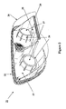
- Figure 1 schematically shows a projector 11 of motor vehicle with a transparent amber screen for direction indicator obtained by the method according to the invention.
- the three elements, case 12, protective glass 16 and mask 13 are made of thermoplastic material by injection.
- the mask 13 has two holes 14 for the lenses of elliptical headlights 17.
- the mask 13 includes a transparent surface 18 of amber color located in front of bulb 15 and acting as a screen for indicator of direction. This surface 18 is an integral part of the mask 13.
- the mask 13 is obtained by injection of a thermoplastic material such as transparent polycarbonate tinted in amber color.
- the mask 13 is then entirely metallized by a layer aluminum.
- a YAG laser operating at a wavelength of 1064 nm, a displacement speed of 900 mm / s, a power of 20 W and a frequency of 4500 Hz.
- a CO 2 laser or a laser of excimer type can also be used.
- a metallic mask 13 is thus obtained except on the surface 18.
- This process therefore allows the realization of a screen function of amber color 18 for flashing without adding an additional part in the projector 11 using only the material of the mask 13.
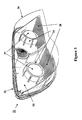
- FIG. 2 schematically represents a projector 21 comprising a light passage obtained by the method according to the invention.
- the three elements, housing 22, protective glass 26 and mask 23 are made of thermoplastic material by injection.
- the mask 23 has two holes 24 for the lenses of elliptical headlights 27.
- the mask 23 includes a transparent and colorless surface 28 located in front of bulb 25 for city lamp. This surface 28 is an integral part mask 23.
- the mask 23 is obtained by injection of a thermoplastic material such as transparent and colorless polycarbonate.
- the mask 23 is then entirely metallized by a layer aluminum.
- a laser of the YAG type is then used to perform a selective ablation of the aluminum layer of the mask 23 corresponding to the surface 28 in order to allow the transparent and colorless plastic material to appear.
- a CO 2 laser or an excimer type laser can also be used.
- a metallic mask 23 is thus obtained except on the surface 28.
- This process therefore allows the realization of an optical function of passage of light for city lamp without adding additional room in the projector 21 using only the material of the mask 23.
- the surface 28 can have different shapes such as a strip or a ring thus allowing to recognize a certain category of vehicle thanks to the shape of the surface lit by city lamps.
- FIG. 3 schematically represents a projector 31 comprising a mask having non-reflective zones obtained by the process according to the invention.
- the three elements, case 32, protective glass 36 and mask 33 are made of thermoplastic material by injection.
- the mask 33 has two holes 34 for the lenses of elliptical searchlights 37.
- the mask 33 includes two surfaces 38 which do not reflect the light.
- the mask 33 is obtained by injection of a material thermoplastic.
- thermoplastic zones corresponding to the surfaces 38 are first grained or textured by exposure to laser radiation of the YAG type.
- a CO 2 laser or an excimer type laser can also be used.
- the mask 33 is then entirely metallized by a layer aluminum.
- a fully metallized mask 33 is thus obtained, comprising two grained and metallized surfaces 38 on which the light does not don't think; this avoids the presence of parasitic light rays.
- This process therefore allows the realization of an optical function of suppression of stray reflections on a metallic mask without special treatment of the mold used to inject the mask.
- Figure 4 shows schematically a horizontal section axial of a crossing / route reflector 40.
- a light source 10 constituted for example by the arc of a gas discharge lamp, is mounted in the reflector 40.
- the reflector 40 has a substantially elliptical inner face 20 which is metallized so as to reflect the light rays emitted by the source 10.
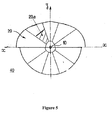
- FIG. 5 schematically represents a front view of the reflector 40 of FIG. 4 according to a first embodiment of the invention.
- the metallized inner face 20 includes a non-metallized zone 20a which does not reflect light. Note that this area 20a can also include a plurality of patterns not reflecting light; in the latter case, the area 20a is partially reflective, the reflection being modular according to the number of patterns.
- the reflector 40 is obtained by injection of a plastic material thermosetting.
- the face 20 of the reflector 40 is then entirely metallized by a aluminum layer.
- a laser of the YAG type is then used to perform a selective ablation of the aluminum layer of the face 20 corresponding to the area 20a in order to allow the plastic to appear.
- a CO 2 laser or an excimer type laser can also be used.
- Figure 6 shows schematically a front view of the reflector 40 of FIG. 4 according to a second embodiment of the invention.
- the reflector 40 as shown in FIG. 6 is identical to that shown in Figure 5 with the difference that it does not include the non- reflective 20a but has a non-reflective area 20b symmetrical of the area 20a with respect to the z axis.
- the process for obtaining such a reflector is identical to the process obtaining as described with reference to Figure 5.
- the method according the invention makes it possible to use the same mask to carry out the two reflectors as described respectively with reference to FIGS. 5 and 6.
- the same brand can be used to make the reflectors used in vehicles driving left and right.
- the laser ablation step selective allows to differentiate the reflectors by integrating one or several non-reflective areas.
- the materials described subjected to laser radiation were plastic and aluminum but it could be other materials such as than other metals.
- the invention has been described only in the case of an implementation shaped by injection but it can also be shaped by stamping, especially when using a material such as sheet metal.
- the description related to an injection of plastic material can also be an injection of a material such as aluminum, the laser radiation acting directly on a surface of the aluminum part.
Applications Claiming Priority (2)
| Application Number | Priority Date | Filing Date | Title |
|---|---|---|---|
| FR0215673 | 2002-12-05 | ||
| FR0215673A FR2848285B1 (fr) | 2002-12-05 | 2002-12-05 | Procede de realisation d'une fonction optique sur un composant d'un dispositif d'eclairage ou de signalisation automobile |
Publications (2)
| Publication Number | Publication Date |
|---|---|
| EP1426676A2 true EP1426676A2 (de) | 2004-06-09 |
| EP1426676A3 EP1426676A3 (de) | 2007-05-02 |
Family
ID=32310036
Family Applications (1)
| Application Number | Title | Priority Date | Filing Date |
|---|---|---|---|
| EP20030292977 Withdrawn EP1426676A3 (de) | 2002-12-05 | 2003-11-28 | Verfahren um eine optische Funktion in einem Komponenten einer Beleuchtungs- oder Signalvorrichtung eines Kraftfahrzeugs zu realisieren |
Country Status (4)
| Country | Link |
|---|---|
| US (1) | US8282998B2 (de) |
| EP (1) | EP1426676A3 (de) |
| JP (1) | JP4741791B2 (de) |
| FR (1) | FR2848285B1 (de) |
Families Citing this family (10)
| Publication number | Priority date | Publication date | Assignee | Title |
|---|---|---|---|---|
| FR2893701B1 (fr) * | 2005-11-24 | 2010-03-26 | Valeo Vision | Dispositif d'eclairage et/ou de signalisation pour automobile |
| FR2901597A1 (fr) | 2006-05-29 | 2007-11-30 | Peugeot Citroen Automobiles Sa | Dispositif d'eclairage et/ou de signalisation a glace metallisee pour vehicule |
| JP5180454B2 (ja) * | 2006-09-13 | 2013-04-10 | 株式会社小糸製作所 | 車両用灯具及びその製造方法 |
| DE102008039930A1 (de) * | 2008-08-27 | 2010-03-04 | Volkswagen Ag | Verfahren zum Herstellen einer Blende für einen Fahrzeugscheinwerfer und Blende für einen Fahrzeugscheinwerfer |
| DE102011002337A1 (de) | 2011-04-29 | 2012-10-31 | Hella Kgaa Hueck & Co. | Projektionsscheinwerfer für Fahrzeuge |
| JP2012243717A (ja) * | 2011-05-24 | 2012-12-10 | Koito Mfg Co Ltd | 車両用灯具の樹脂製品及びその製造方法 |
| FR3047939B1 (fr) * | 2016-02-18 | 2019-04-05 | Valeo Vision | Ensemble lumineux pour l'eclairage et/ou la signalisation d'un vehicule automobile. |
| CN106641957B (zh) * | 2016-11-10 | 2019-11-08 | 宁波雅佳达电器有限公司 | 一种车前灯 |
| US10288249B2 (en) | 2017-07-26 | 2019-05-14 | Ford Global Technologies, Llc | Pattern styling for reducing glare in vehicle lighting assemblies |
| CZ308371B6 (cs) * | 2019-04-05 | 2020-07-01 | Varroc Lighting Systems, s.r.o. | Optická soustava pro světelné zařízení motorového vozidla |
Citations (1)
| Publication number | Priority date | Publication date | Assignee | Title |
|---|---|---|---|---|
| GB2337321A (en) * | 1998-05-12 | 1999-11-17 | Koito Mfg Co Ltd | Automobile headlamp comprising a floodlight lamp disposed above a reflector lamp |
Family Cites Families (25)
| Publication number | Priority date | Publication date | Assignee | Title |
|---|---|---|---|---|
| US4327283A (en) * | 1979-09-24 | 1982-04-27 | Rca Corporation | Workpiece with machine-readable marking recessed therein and method of making same |
| EP0065240A1 (de) * | 1981-05-12 | 1982-11-24 | Minigrip Europe Gmbh | Aufblasbares Trennwandelement |
| DE3621685A1 (de) * | 1986-06-27 | 1988-01-14 | Basf Ag | Lichtempfindliches aufzeichnungsmaterial |
| GB2244934B (en) * | 1990-05-29 | 1994-11-30 | Retriever Sports Ltd | A dart flight |
| JPH04155702A (ja) * | 1990-10-19 | 1992-05-28 | Toyoda Gosei Co Ltd | 車両用表示装置 |
| US5347435A (en) * | 1992-12-22 | 1994-09-13 | Hughes Aircraft Company | Linear lamp holographic trapped beam center high mounted stoplight |
| US5614338A (en) * | 1995-04-14 | 1997-03-25 | Delco Electronics Corporation | Process for manufacturing backlit displays utilizing treated plastics and laser energy |
| GB9522925D0 (en) * | 1995-11-09 | 1996-01-10 | Barr & Stroud Ltd | Solid state lasers |
| US5817243A (en) * | 1996-10-30 | 1998-10-06 | Shaffer; Wayne K. | Method for applying decorative contrast designs to automotive and motorcycle parts using lasers |
| FR2755748B1 (fr) * | 1996-11-08 | 1999-01-29 | Valeo Vision | Projecteur de vehicule automobile, comportant une lampe a decharge a occulteurs et un reflecteur multi-zones |
| JPH10204655A (ja) * | 1997-01-17 | 1998-08-04 | Toyota Motor Corp | 皮膜形成方法 |
| US6441943B1 (en) * | 1997-04-02 | 2002-08-27 | Gentex Corporation | Indicators and illuminators using a semiconductor radiation emitter package |
| US5977514A (en) * | 1997-06-13 | 1999-11-02 | M.A. Hannacolor | Controlled color laser marking of plastics |
| US5911317A (en) * | 1997-08-26 | 1999-06-15 | Silitek Corporation | Light permeable metal plated rubber key |
| US5997162A (en) * | 1998-03-13 | 1999-12-07 | Osram Sylvania Inc. | Horizontal HID vehicle headlamp with magnetic deflection |
| US6012830A (en) * | 1998-06-23 | 2000-01-11 | Valeo Sylvania L.L.C. | Light shield for a vehicle headlamp |
| JP3103797B2 (ja) * | 1998-12-10 | 2000-10-30 | 株式会社サンリツ | 透明素材への文字・数字・記号・絵柄等の加工方法 |
| DE19929301A1 (de) * | 1999-06-25 | 2000-12-28 | Basf Ag | Aus mit Epoxypolymeren vorbehandelten glasfaserverstärkten Formteilen geschweißte Verbunde |
| FR2802704B1 (fr) * | 1999-12-15 | 2004-02-13 | Rudolf Wendel | Ampoule electrique a miroir et rampe d'eclairage comportant au moins une telle ampoule |
| DE10010740A1 (de) * | 2000-03-04 | 2001-09-06 | Valeo Schalter & Sensoren Gmbh | Elektrisches Schaltelement für ein Kraftfahrzeug mit separatem Symbolfeld |
| DE10018600A1 (de) * | 2000-04-14 | 2001-10-25 | Merck Patent Gmbh | Lasermarkierbare Kunststoffe |
| US6768654B2 (en) * | 2000-09-18 | 2004-07-27 | Wavezero, Inc. | Multi-layered structures and methods for manufacturing the multi-layered structures |
| FR2819040B1 (fr) * | 2001-01-02 | 2003-09-12 | Valeo Vision | Composant d'optique ou de style pour dispositif d'eclairage ou de signalisation pour vehicule automobile |
| US6885767B1 (en) * | 2001-05-11 | 2005-04-26 | Paul Howell | Silhouetting apparatus and method |
| US20040145289A1 (en) * | 2003-01-27 | 2004-07-29 | 3M Innovative Properties Company | Phosphor based light sources having a non-planar short pass reflector and method of making |
-
2002
- 2002-12-05 FR FR0215673A patent/FR2848285B1/fr not_active Expired - Fee Related
-
2003
- 2003-11-28 EP EP20030292977 patent/EP1426676A3/de not_active Withdrawn
- 2003-12-04 US US10/729,184 patent/US8282998B2/en not_active Expired - Fee Related
- 2003-12-05 JP JP2003407708A patent/JP4741791B2/ja not_active Expired - Fee Related
Patent Citations (1)
| Publication number | Priority date | Publication date | Assignee | Title |
|---|---|---|---|---|
| GB2337321A (en) * | 1998-05-12 | 1999-11-17 | Koito Mfg Co Ltd | Automobile headlamp comprising a floodlight lamp disposed above a reflector lamp |
Also Published As
| Publication number | Publication date |
|---|---|
| JP2004186162A (ja) | 2004-07-02 |
| US8282998B2 (en) | 2012-10-09 |
| JP4741791B2 (ja) | 2011-08-10 |
| FR2848285B1 (fr) | 2005-12-16 |
| EP1426676A3 (de) | 2007-05-02 |
| US20040170847A1 (en) | 2004-09-02 |
| FR2848285A1 (fr) | 2004-06-11 |
Similar Documents
| Publication | Publication Date | Title |
|---|---|---|
| EP3067618B1 (de) | Leuchtvorrichtung mit optischen wellenleitern | |
| EP1775511B1 (de) | Kfz-Signal- und/oder Beleuchtungseinrichtung mit einem Lichtleiter | |
| EP3014172B1 (de) | Indirektbeleuchtungsvorrichtung für ein kraftfahrzeugrücklicht | |
| EP1610158B1 (de) | Signalvorrichtung mit Lichtleiter | |
| FR2851030A1 (fr) | Phare de vehicule a source, reflecteur et lentille | |
| JP2000025519A (ja) | 車両用サイドミラー | |
| EP1426676A2 (de) | Verfahren um eine optische Funktion in einem Komponenten einer Beleuchtungs- oder Signalvorrichtung eines Kraftfahrzeugs zu realisieren | |
| FR2819040A1 (fr) | Composant d'optique ou de style pour dispositif d'eclairage ou de signalisation pour vehicule automobile | |
| FR2590351A1 (fr) | Feu de signalisation a double fonction pour vehicule | |
| EP3625501B1 (de) | Signallicht für ein kraftfahrzeug | |
| EP3214364B1 (de) | Verbesserte linse für beleuchtungsvorrichtung eines kraftfahrzeugs | |
| EP0632228B1 (de) | Stylistisches oder optisches Element- mit glänzendem Aussehen und neutraler Farbe- für Kfz-Beleuchtungs- oder Anzeige-Scheinwerfer | |
| EP2926049B1 (de) | Fahrzeugsignalisierungsvorrichtung mit dreidimensionaler wirkung | |
| FR3105354A1 (fr) | Dispositif lumineux pour véhicule | |
| FR2919913A1 (fr) | Module optique pour dispositif d'eclairage et/ou de signalisation de vehicule | |
| EP1488954B1 (de) | Beleuchtungs- oder Signalisierungssystem für Fahrzeuge | |
| FR2848286A1 (fr) | Procede de realisation d'un motif decoratif sur un composant d'un dispositif d'eclairage ou de signalisation automobile | |
| EP1862728A1 (de) | Beleuchtungs- und/oder Signalvorrichtungen für Fahrzeuge mit einer metallisierten Abdeckscheibe | |
| EP1271050A1 (de) | Beleuchtungs-oder Signal-Vorrichtung für Kraftfahrzeuge mit einem verbesserten Aussehen | |
| EP0451039B1 (de) | Zwischenscheibe für Fahrzeugrückleuchte und Herstellungsverfahren | |
| EP1344975B1 (de) | Optisches oder gestalterisches Bauelement für eine Beleuchtungs- oder Anzeigevorrichtung für Kraftfahrzeuge | |
| EP1813860B1 (de) | Verdunklungselement des Reflektors eines Scheinwerfers und Verfahren zur Montage eines solchen Elementes | |
| CN211902725U (zh) | 灯罩和灯具 | |
| JP2019096462A (ja) | 樹脂成形品および車両用灯具 | |
| WO2023213807A1 (fr) | Dispositif lumineux pour véhicule comprenant une glace de sortie et un écran intermédiaire |
Legal Events
| Date | Code | Title | Description |
|---|---|---|---|
| PUAI | Public reference made under article 153(3) epc to a published international application that has entered the european phase |
Free format text: ORIGINAL CODE: 0009012 |
|
| AK | Designated contracting states |
Kind code of ref document: A2 Designated state(s): AT BE BG CH CY CZ DE DK EE ES FI FR GB GR HU IE IT LI LU MC NL PT RO SE SI SK TR |
|
| AX | Request for extension of the european patent |
Extension state: AL LT LV MK |
|
| PUAL | Search report despatched |
Free format text: ORIGINAL CODE: 0009013 |
|
| AK | Designated contracting states |
Kind code of ref document: A3 Designated state(s): AT BE BG CH CY CZ DE DK EE ES FI FR GB GR HU IE IT LI LU MC NL PT RO SE SI SK TR |
|
| AX | Request for extension of the european patent |
Extension state: AL LT LV MK |
|
| RIC1 | Information provided on ipc code assigned before grant |
Ipc: F21V 11/16 20060101AFI20040309BHEP Ipc: F21S 8/10 20060101ALI20070326BHEP Ipc: B60Q 1/00 20060101ALI20070326BHEP |
|
| 17P | Request for examination filed |
Effective date: 20071010 |
|
| 17Q | First examination report despatched |
Effective date: 20071123 |
|
| AKX | Designation fees paid |
Designated state(s): AT BE BG CH CY CZ DE DK EE ES FI FR GB GR HU IE IT LI LU MC NL PT RO SE SI SK TR |
|
| APBK | Appeal reference recorded |
Free format text: ORIGINAL CODE: EPIDOSNREFNE |
|
| APBN | Date of receipt of notice of appeal recorded |
Free format text: ORIGINAL CODE: EPIDOSNNOA2E |
|
| APBR | Date of receipt of statement of grounds of appeal recorded |
Free format text: ORIGINAL CODE: EPIDOSNNOA3E |
|
| APAF | Appeal reference modified |
Free format text: ORIGINAL CODE: EPIDOSCREFNE |
|
| APBT | Appeal procedure closed |
Free format text: ORIGINAL CODE: EPIDOSNNOA9E |
|
| STAA | Information on the status of an ep patent application or granted ep patent |
Free format text: STATUS: THE APPLICATION HAS BEEN WITHDRAWN |
|
| 18W | Application withdrawn |
Effective date: 20170830 |