EP1426676A2 - Method for realising an optical function in a component of an automobile illumination or signalling device - Google Patents
Method for realising an optical function in a component of an automobile illumination or signalling device Download PDFInfo
- Publication number
- EP1426676A2 EP1426676A2 EP20030292977 EP03292977A EP1426676A2 EP 1426676 A2 EP1426676 A2 EP 1426676A2 EP 20030292977 EP20030292977 EP 20030292977 EP 03292977 A EP03292977 A EP 03292977A EP 1426676 A2 EP1426676 A2 EP 1426676A2
- Authority
- EP
- European Patent Office
- Prior art keywords
- component
- mask
- laser radiation
- laser
- metallized
- Prior art date
- Legal status (The legal status is an assumption and is not a legal conclusion. Google has not performed a legal analysis and makes no representation as to the accuracy of the status listed.)
- Withdrawn
Links
Images


Classifications
-
- B—PERFORMING OPERATIONS; TRANSPORTING
- B60—VEHICLES IN GENERAL
- B60Q—ARRANGEMENT OF SIGNALLING OR LIGHTING DEVICES, THE MOUNTING OR SUPPORTING THEREOF OR CIRCUITS THEREFOR, FOR VEHICLES IN GENERAL
- B60Q1/00—Arrangement of optical signalling or lighting devices, the mounting or supporting thereof or circuits therefor
- B60Q1/0029—Spatial arrangement
- B60Q1/0041—Spatial arrangement of several lamps in relation to each other
-
- F—MECHANICAL ENGINEERING; LIGHTING; HEATING; WEAPONS; BLASTING
- F21—LIGHTING
- F21S—NON-PORTABLE LIGHTING DEVICES; SYSTEMS THEREOF; VEHICLE LIGHTING DEVICES SPECIALLY ADAPTED FOR VEHICLE EXTERIORS
- F21S41/00—Illuminating devices specially adapted for vehicle exteriors, e.g. headlamps
- F21S41/30—Illuminating devices specially adapted for vehicle exteriors, e.g. headlamps characterised by reflectors
- F21S41/37—Illuminating devices specially adapted for vehicle exteriors, e.g. headlamps characterised by reflectors characterised by their material, surface treatment or coatings
-
- F—MECHANICAL ENGINEERING; LIGHTING; HEATING; WEAPONS; BLASTING
- F21—LIGHTING
- F21S—NON-PORTABLE LIGHTING DEVICES; SYSTEMS THEREOF; VEHICLE LIGHTING DEVICES SPECIALLY ADAPTED FOR VEHICLE EXTERIORS
- F21S43/00—Signalling devices specially adapted for vehicle exteriors, e.g. brake lamps, direction indicator lights or reversing lights
- F21S43/30—Signalling devices specially adapted for vehicle exteriors, e.g. brake lamps, direction indicator lights or reversing lights characterised by reflectors
- F21S43/33—Signalling devices specially adapted for vehicle exteriors, e.g. brake lamps, direction indicator lights or reversing lights characterised by reflectors characterised by their material, surface treatment or coatings
-
- F—MECHANICAL ENGINEERING; LIGHTING; HEATING; WEAPONS; BLASTING
- F21—LIGHTING
- F21S—NON-PORTABLE LIGHTING DEVICES; SYSTEMS THEREOF; VEHICLE LIGHTING DEVICES SPECIALLY ADAPTED FOR VEHICLE EXTERIORS
- F21S43/00—Signalling devices specially adapted for vehicle exteriors, e.g. brake lamps, direction indicator lights or reversing lights
- F21S43/50—Signalling devices specially adapted for vehicle exteriors, e.g. brake lamps, direction indicator lights or reversing lights characterised by aesthetic components not otherwise provided for, e.g. decorative trim, partition walls or covers
-
- F—MECHANICAL ENGINEERING; LIGHTING; HEATING; WEAPONS; BLASTING
- F21—LIGHTING
- F21V—FUNCTIONAL FEATURES OR DETAILS OF LIGHTING DEVICES OR SYSTEMS THEREOF; STRUCTURAL COMBINATIONS OF LIGHTING DEVICES WITH OTHER ARTICLES, NOT OTHERWISE PROVIDED FOR
- F21V7/00—Reflectors for light sources
- F21V7/22—Reflectors for light sources characterised by materials, surface treatments or coatings, e.g. dichroic reflectors
- F21V7/24—Reflectors for light sources characterised by materials, surface treatments or coatings, e.g. dichroic reflectors characterised by the material
-
- Y—GENERAL TAGGING OF NEW TECHNOLOGICAL DEVELOPMENTS; GENERAL TAGGING OF CROSS-SECTIONAL TECHNOLOGIES SPANNING OVER SEVERAL SECTIONS OF THE IPC; TECHNICAL SUBJECTS COVERED BY FORMER USPC CROSS-REFERENCE ART COLLECTIONS [XRACs] AND DIGESTS
- Y10—TECHNICAL SUBJECTS COVERED BY FORMER USPC
- Y10T—TECHNICAL SUBJECTS COVERED BY FORMER US CLASSIFICATION
- Y10T428/00—Stock material or miscellaneous articles
- Y10T428/31504—Composite [nonstructural laminate]
- Y10T428/31678—Of metal
- Y10T428/31681—Next to polyester, polyamide or polyimide [e.g., alkyd, glue, or nylon, etc.]
Definitions
- the present invention relates to a method for producing a optical function on a component of a lighting device or automotive signage. This process is more particularly suited to the realization of mask for headlamp or light or reflector.
- the mask of an automobile headlamp must be metallized.
- This mask can cover not only the code lights, road lights, the city lamp but also the direction indicator.
- a transparent amber screen must then be placed in front of the direction indicator.
- One solution is to use a piece of plastic material of amber color suitable for the mask; this piece is attached to the mask.
- the metallization of the mask also causes the reflection of the light in certain areas thus causing light rays parasites.
- One solution is to mattify the areas causing parasitic light rays by texturing (grain, streaks) of the mold manufacture of the mask.
- the mold can easily wear out or be contaminated with impurities.
- the stray reflection zones are not located at the same location of the reflector depending on whether it is used for a rolling vehicle To the right or to the left. Two different molds are therefore necessary for make these two types of reflectors.
- the material used is a material thermosetting, injected metal or stamped sheet because the reflector is used for high beams that heat to high temperatures thereby making it impossible to use a thermoplastic material; for this type of thermosetting material, the graining of the mold is impossible because it causes crumbling problems at the time of demolding.
- the present invention aims to provide a method for producing a optical function on a component of a lighting device or automotive signage to add at low cost and in a space restricted optical functions such as an amber screen for direction indicator in a spotlight and use molds without texturing or special marking for the realization of matt area on parts such as masks.
- the present invention provides for this purpose a method of making of an optical function on a component of a lighting device or automotive signaling comprising a step of shaping said component in a predetermined material.
- said method comprises a step of exposure to a laser radiation from at least one surface of said component.
- a shaped component for example by molding, in a material such as a plastic which can be metallic or not. Laser technology then enables either selective ablation on said component when the latter is metallized either exposure directly on the plastic.
- This area corresponds to an optical function such as a screen.
- Exposing the laser directly to the plastic allows example of graining part of the plastic surface, this part becoming less reflective after metallization.
- Such a method therefore makes it possible to start from a component without marking and offers great flexibility of use for carrying out particular optical functions or areas of lesser reflection.
- the process does not involve adaptation of the mask or additional part.
- This method also makes it possible to create light passages through a room such as a mask made of metallized transparent plastic material by creating, by ablation of a metal surface, a window of light for example for a city lamp.
- the method can also include a metallization step of said component.
- the method comprises a complete metallization step of said component prior to said step of exposure to laser radiation, said exposure step being a step of selective ablation by laser radiation of the metal of said surface of said metallized component.
- the predetermined material is a plastic material and said step of exposure to laser radiation is a step of graining said plastic surface.
- said graining step is followed by a step of metallization of said component.
- the laser radiation is produced by means of a YAG laser, a CO 2 laser or an excimer laser.
- the present invention also relates to a component of a automotive lighting or signaling device obtained by the process according to the invention, said component being of a predetermined material and comprising at least one surface obtained after exposure to a laser radiation.
- the present invention further relates to a component of a lighting or signaling device obtained by the process according to the invention, said component being made of plastic and comprising a metallized surface and a non-metallized surface obtained after ablation selective of metal by laser radiation.
- said plastic material is transparent and amber in color.
- This embodiment allows for example to produce a screen of amber color for flashing on a projector mask.
- said plastic material is transparent is colorless.
- This embodiment allows for example to make a passage of light, for example in the city lamp part of a mask projector.
- the present invention finally relates to a component of a device lighting obtained by the method according to the invention, said component being in metallized plastic material and having a surface reflecting the light and a surface that does not reflect light.
- said component comprises a plurality of non-light reflecting surfaces and a plurality of surfaces reflecting light.
- said plastic material is a thermosetting material.
- a reflector having reflecting surfaces light to exercise their optical function and surfaces not reflective to overcome parasitic reflections.
- the non-reflective surface is obtained either by graining the material plastic then metallization either by attacking a metallized part in order to change the texture of the metal.
- a plurality of surfaces can be produced not reflecting light in the same area, the reflection of light being lower the higher the number of surfaces.
- said plastic material is a thermoplastic material.
- This second alternative makes it possible for example to carry out masks for metallic projector for aesthetic reasons and to treat surfaces likely to reflect stray rays.
- said predetermined material is a metal such as aluminum.
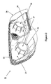
- Figure 1 schematically shows a projector 11 of motor vehicle with a transparent amber screen for direction indicator obtained by the method according to the invention.
- the three elements, case 12, protective glass 16 and mask 13 are made of thermoplastic material by injection.
- the mask 13 has two holes 14 for the lenses of elliptical headlights 17.
- the mask 13 includes a transparent surface 18 of amber color located in front of bulb 15 and acting as a screen for indicator of direction. This surface 18 is an integral part of the mask 13.
- the mask 13 is obtained by injection of a thermoplastic material such as transparent polycarbonate tinted in amber color.
- the mask 13 is then entirely metallized by a layer aluminum.
- a YAG laser operating at a wavelength of 1064 nm, a displacement speed of 900 mm / s, a power of 20 W and a frequency of 4500 Hz.
- a CO 2 laser or a laser of excimer type can also be used.
- a metallic mask 13 is thus obtained except on the surface 18.
- This process therefore allows the realization of a screen function of amber color 18 for flashing without adding an additional part in the projector 11 using only the material of the mask 13.
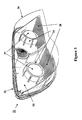
- FIG. 2 schematically represents a projector 21 comprising a light passage obtained by the method according to the invention.
- the three elements, housing 22, protective glass 26 and mask 23 are made of thermoplastic material by injection.
- the mask 23 has two holes 24 for the lenses of elliptical headlights 27.
- the mask 23 includes a transparent and colorless surface 28 located in front of bulb 25 for city lamp. This surface 28 is an integral part mask 23.
- the mask 23 is obtained by injection of a thermoplastic material such as transparent and colorless polycarbonate.
- the mask 23 is then entirely metallized by a layer aluminum.
- a laser of the YAG type is then used to perform a selective ablation of the aluminum layer of the mask 23 corresponding to the surface 28 in order to allow the transparent and colorless plastic material to appear.
- a CO 2 laser or an excimer type laser can also be used.
- a metallic mask 23 is thus obtained except on the surface 28.
- This process therefore allows the realization of an optical function of passage of light for city lamp without adding additional room in the projector 21 using only the material of the mask 23.
- the surface 28 can have different shapes such as a strip or a ring thus allowing to recognize a certain category of vehicle thanks to the shape of the surface lit by city lamps.
- FIG. 3 schematically represents a projector 31 comprising a mask having non-reflective zones obtained by the process according to the invention.
- the three elements, case 32, protective glass 36 and mask 33 are made of thermoplastic material by injection.
- the mask 33 has two holes 34 for the lenses of elliptical searchlights 37.
- the mask 33 includes two surfaces 38 which do not reflect the light.
- the mask 33 is obtained by injection of a material thermoplastic.
- thermoplastic zones corresponding to the surfaces 38 are first grained or textured by exposure to laser radiation of the YAG type.
- a CO 2 laser or an excimer type laser can also be used.
- the mask 33 is then entirely metallized by a layer aluminum.
- a fully metallized mask 33 is thus obtained, comprising two grained and metallized surfaces 38 on which the light does not don't think; this avoids the presence of parasitic light rays.
- This process therefore allows the realization of an optical function of suppression of stray reflections on a metallic mask without special treatment of the mold used to inject the mask.
- Figure 4 shows schematically a horizontal section axial of a crossing / route reflector 40.
- a light source 10 constituted for example by the arc of a gas discharge lamp, is mounted in the reflector 40.
- the reflector 40 has a substantially elliptical inner face 20 which is metallized so as to reflect the light rays emitted by the source 10.
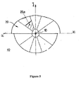
- FIG. 5 schematically represents a front view of the reflector 40 of FIG. 4 according to a first embodiment of the invention.
- the metallized inner face 20 includes a non-metallized zone 20a which does not reflect light. Note that this area 20a can also include a plurality of patterns not reflecting light; in the latter case, the area 20a is partially reflective, the reflection being modular according to the number of patterns.
- the reflector 40 is obtained by injection of a plastic material thermosetting.
- the face 20 of the reflector 40 is then entirely metallized by a aluminum layer.
- a laser of the YAG type is then used to perform a selective ablation of the aluminum layer of the face 20 corresponding to the area 20a in order to allow the plastic to appear.
- a CO 2 laser or an excimer type laser can also be used.
- Figure 6 shows schematically a front view of the reflector 40 of FIG. 4 according to a second embodiment of the invention.
- the reflector 40 as shown in FIG. 6 is identical to that shown in Figure 5 with the difference that it does not include the non- reflective 20a but has a non-reflective area 20b symmetrical of the area 20a with respect to the z axis.
- the process for obtaining such a reflector is identical to the process obtaining as described with reference to Figure 5.
- the method according the invention makes it possible to use the same mask to carry out the two reflectors as described respectively with reference to FIGS. 5 and 6.
- the same brand can be used to make the reflectors used in vehicles driving left and right.
- the laser ablation step selective allows to differentiate the reflectors by integrating one or several non-reflective areas.
- the materials described subjected to laser radiation were plastic and aluminum but it could be other materials such as than other metals.
- the invention has been described only in the case of an implementation shaped by injection but it can also be shaped by stamping, especially when using a material such as sheet metal.
- the description related to an injection of plastic material can also be an injection of a material such as aluminum, the laser radiation acting directly on a surface of the aluminum part.
Abstract
Description
La présente invention concerne un procédé de réalisation d'une fonction optique sur un composant d'un dispositif d'éclairage ou de signalisation automobile. Ce procédé est plus particulièrement adapté à la réalisation de masque pour projecteur ou feu ou de réflecteur.The present invention relates to a method for producing a optical function on a component of a lighting device or automotive signage. This process is more particularly suited to the realization of mask for headlamp or light or reflector.
Très souvent, pour des raisons optiques et/ou esthétiques, le masque d'un projecteur automobile doit être métallisé. Ce masque peut recouvrir non seulement les feux de code, de route, la lampe ville mais également l'indicateur de direction. Un écran transparent de couleur ambre doit alors être placé devant l'indicateur de direction.Very often, for optical and / or aesthetic reasons, the mask of an automobile headlamp must be metallized. This mask can cover not only the code lights, road lights, the city lamp but also the direction indicator. A transparent amber screen must then be placed in front of the direction indicator.
Une solution consiste à utiliser une pièce en matériau plastique de couleur ambre adaptée au masque ; cette pièce est fixée sur le masque.One solution is to use a piece of plastic material of amber color suitable for the mask; this piece is attached to the mask.
Toutefois, l'ajout de cette pièce additionnelle entraíne un surcoût important dû non seulement au coût de la pièce elle-même mais égaiement à l'assemblage du masque et de la pièce.However, the addition of this additional part entails an additional cost important due not only to the cost of the part itself but also to the assembly of the mask and the part.
La métallisation du masque entraíne en outre la réflexion de la lumière dans certaines zones provoquant ainsi des rayons lumineux parasites. On peut également retrouver des zones de réflexion parasite au niveau du réflecteur du projecteur qui est lui aussi métallisé pour exercer sa fonction optique de réflexion.The metallization of the mask also causes the reflection of the light in certain areas thus causing light rays parasites. We can also find parasitic reflection zones at level of the reflector of the projector which is also metallized to exert its optical reflection function.
Une solution consiste à rendre mates les zones provoquant des rayons lumineux parasites par texturation (grainages, stries) du moule de fabrication du masque.One solution is to mattify the areas causing parasitic light rays by texturing (grain, streaks) of the mold manufacture of the mask.
La mise en oeuvre d'une telle solution entraíne cependant certains problèmes.The implementation of such a solution, however, entails certain problems.
En effet, l'utilisation d'un moule avec une texturation particulière rend peu flexible l'utilisation de ce moule à d'autres applications.Indeed, the use of a mold with a particular texturing makes inflexible the use of this mold for other applications.
De plus, le moule peut facilement s'user ou être contaminé par des impuretés. In addition, the mold can easily wear out or be contaminated with impurities.
En outre, les zones de réflexion parasite ne se situent pas au même endroit du réflecteur selon que ce dernier est utilisé pour un véhicule roulant à droite ou à gauche. Deux moules différents sont donc nécessaires pour réaliser ces deux types de réflecteurs.In addition, the stray reflection zones are not located at the same location of the reflector depending on whether it is used for a rolling vehicle To the right or to the left. Two different molds are therefore necessary for make these two types of reflectors.
Enfin, dans le cas d'un réflecteur, le matériau utilisé est un matériau thermodurcissable, un métal injecté ou une tôle emboutie car le réflecteur est utilisé pour les feux de route qui chauffent à des températures élevées rendant impossible de ce fait l'utilisation d'un matériau thermoplastique ; pour ce type de matériau thermodurcissable, le grainage du moule est impossible car il entraíne des problèmes d'effritement au moment du démoulage.Finally, in the case of a reflector, the material used is a material thermosetting, injected metal or stamped sheet because the reflector is used for high beams that heat to high temperatures thereby making it impossible to use a thermoplastic material; for this type of thermosetting material, the graining of the mold is impossible because it causes crumbling problems at the time of demolding.
La présente invention vise à fournir un procédé de réalisation d'une fonction optique sur un composant d'un dispositif d'éclairage ou de signalisation automobile permettant d'ajouter à bas coût et dans un espace restreint des fonctions optiques telles qu'un écran de couleur ambre pour indicateur de direction dans un projecteur et d'utiliser des moules sans texturation ou marquage particulier pour la réalisation de zone mat sur des pièces telles que les masques.The present invention aims to provide a method for producing a optical function on a component of a lighting device or automotive signage to add at low cost and in a space restricted optical functions such as an amber screen for direction indicator in a spotlight and use molds without texturing or special marking for the realization of matt area on parts such as masks.
La présente invention propose à cet effet un procédé de réalisation d'une fonction optique sur un composant d'un dispositif d'éclairage ou de signalisation automobile comportant une étape de mise en forme dudit composant dans une matière prédéterminée.The present invention provides for this purpose a method of making of an optical function on a component of a lighting device or automotive signaling comprising a step of shaping said component in a predetermined material.
Selon l'invention, ledit procédé comporte une étape d'exposition à un rayonnement laser d'au moins une surface dudit composant.According to the invention, said method comprises a step of exposure to a laser radiation from at least one surface of said component.
On part ainsi d'un composant mis en forme, par exemple par moulage, dans une matière telle qu'une matière plastique qui peut être métallisée ou non. La technologie laser permet ensuite de réaliser soit une ablation sélective sur ledit composant lorsque celui ci est métallisé soit une exposition directement sur la matière plastique.We start from a shaped component, for example by molding, in a material such as a plastic which can be metallic or not. Laser technology then enables either selective ablation on said component when the latter is metallized either exposure directly on the plastic.
L'ablation d'une surface métallique particulière n'affecte pas la matière plastique et laisse donc apparaítre une zone de matière plastique. Cette zone correspond à une fonction optique telle qu'un écran. The ablation of a particular metal surface does not affect the plastic and therefore lets appear a plastic area. This area corresponds to an optical function such as a screen.
L'exposition du laser directement sur la matière plastique permet par exemple de grainer une partie de la surface plastique, cette partie devenant moins réfléchissante après métallisation.Exposing the laser directly to the plastic allows example of graining part of the plastic surface, this part becoming less reflective after metallization.
Un tel procédé permet donc de partir d'un composant sans
marquage et offre une grande flexibilité d'utilisation pour réaliser des
fonctions optiques particulières ou des zones de réflexion moins importante.
Le procédé n'implique ni adaptation du masque ni pièce additionnelle.
Ce procédé permet également de créer des passages de lumière à travers
une pièce tel qu'un masque en matière plastique transparent métallisé en
créant, par ablation d'une surface métallique, une fenêtre de lumière par
exemple pour une lampe ville.Such a method therefore makes it possible to start from a component without marking and offers great flexibility of use for carrying out particular optical functions or areas of lesser reflection. The process does not involve adaptation of the mask or additional part.
This method also makes it possible to create light passages through a room such as a mask made of metallized transparent plastic material by creating, by ablation of a metal surface, a window of light for example for a city lamp.
Le procédé peut également comporter une étape de métallisation dudit composant.The method can also include a metallization step of said component.
Selon un premier mode de réalisation, le procédé comporte une étape de métallisation complète dudit composant préalable à ladite étape d'exposition à un rayonnement laser, ladite étape d'exposition étant une étape d'ablation sélective par rayonnement laser du métal de ladite surface dudit composant métallisé.According to a first embodiment, the method comprises a complete metallization step of said component prior to said step of exposure to laser radiation, said exposure step being a step of selective ablation by laser radiation of the metal of said surface of said metallized component.
Selon un deuxième mode de réalisation, la matière prédéterminée est une matière plastique et ladite étape d'exposition à un rayonnement laser est une étape de grainage de ladite surface en matière plastique.According to a second embodiment, the predetermined material is a plastic material and said step of exposure to laser radiation is a step of graining said plastic surface.
Avantageusement, ladite étape de grainage est suivie d'une étape de métallisation dudit composant.Advantageously, said graining step is followed by a step of metallization of said component.
Avantageusement, le rayonnement laser est réalisé au moyen d'un laser YAG, d'un laser CO2 ou d'un laser excimère..Advantageously, the laser radiation is produced by means of a YAG laser, a CO 2 laser or an excimer laser.
La présente invention a également pour objet un composant d'un dispositif d'éclairage ou de signalisation automobile obtenu par le procédé selon l'invention, ledit composant étant en une matière prédéterminée et comportant au moins une surface obtenue après exposition à un rayonnement laser.The present invention also relates to a component of a automotive lighting or signaling device obtained by the process according to the invention, said component being of a predetermined material and comprising at least one surface obtained after exposure to a laser radiation.
La présente invention a en outre pour objet un composant d'un dispositif d'éclairage ou de signalisation obtenu par le procédé selon l'invention, ledit composant étant en matière plastique et comportant une surface métallisée et une surface non métallisée obtenue après ablation sélective du métal par rayonnement laser.The present invention further relates to a component of a lighting or signaling device obtained by the process according to the invention, said component being made of plastic and comprising a metallized surface and a non-metallized surface obtained after ablation selective of metal by laser radiation.
Selon un mode de réalisation, ladite matière plastique est transparente et de couleur ambre.According to one embodiment, said plastic material is transparent and amber in color.
Ce mode de réalisation permet par exemple de réaliser un écran de couleur ambre pour clignotant sur un masque de projecteur.This embodiment allows for example to produce a screen of amber color for flashing on a projector mask.
Selon un autre mode de réalisation, ladite matière plastique est transparente est incolore.According to another embodiment, said plastic material is transparent is colorless.
Ce mode de réalisation permet par exemple de réaliser un passage de lumière, par exemple dans la partie lampe ville d'un masque de projecteur.This embodiment allows for example to make a passage of light, for example in the city lamp part of a mask projector.
La présente invention a enfin pour objet un composant d'un dispositif d'éclairage obtenu par le procédé selon l'invention, ledit composant étant en matière plastique métallisée et comportant une surface réfléchissant la lumière et une surface ne réfléchissant pas la lumière.The present invention finally relates to a component of a device lighting obtained by the method according to the invention, said component being in metallized plastic material and having a surface reflecting the light and a surface that does not reflect light.
Avantageusement, ledit composant comporte une pluralité de surfaces ne réfléchissant pas la lumière et une pluralité de surfaces réfléchissant la lumière.Advantageously, said component comprises a plurality of non-light reflecting surfaces and a plurality of surfaces reflecting light.
Selon une première alternative, ladite matière plastique est une matière thermodurcissable.According to a first alternative, said plastic material is a thermosetting material.
Ainsi, on peut réaliser un réflecteur ayant des surfaces réfléchissant la lumière pour exercer leur fonction optique et des surfaces non réfléchissantes permettant de s'affranchir des réflexions parasites. La surface non réfléchissante est obtenue soit par grainage du matériau plastique puis métallisation soit par attaque d'une partie métallisée afin de modifier la texture du métal. On peut réaliser une pluralité de surfaces ne réfléchissant pas la lumière dans une même zone, la réflexion de la lumière étant d'autant plus faible que le nombre de surfaces est élevé. On peut en outre utiliser un seul moule de fabrication pour réaliser deux types de réflecteurs selon que le véhicule roule à gauche ou à droite, l'étape d'exposition sélective à un rayonnement laser permettant de différencier les réflecteurs.Thus, it is possible to produce a reflector having reflecting surfaces light to exercise their optical function and surfaces not reflective to overcome parasitic reflections. The non-reflective surface is obtained either by graining the material plastic then metallization either by attacking a metallized part in order to change the texture of the metal. A plurality of surfaces can be produced not reflecting light in the same area, the reflection of light being lower the higher the number of surfaces. We can in addition to using a single manufacturing mold to make two types of reflectors depending on whether the vehicle is driving on the left or on the right, the stage selective exposure to laser radiation to differentiate between reflectors.
Selon une seconde alternative, ladite matière plastique est une matière thermoplastique.According to a second alternative, said plastic material is a thermoplastic material.
Cette seconde alternative permet par exemple de réaliser des masques pour projecteur métallisé pour des raisons esthétiques et de traiter les surfaces risquant de réfléchir les rayons parasites.This second alternative makes it possible for example to carry out masks for metallic projector for aesthetic reasons and to treat surfaces likely to reflect stray rays.
Selon un autre mode de réalisation, ladite matière prédéterminée est un métal tel que l'aluminium.According to another embodiment, said predetermined material is a metal such as aluminum.
D'autres caractéristiques et avantages de la présente invention apparaítront dans la description suivante de modes de réalisation de l'invention, donnés à titre illustratif et nullement limitatif.Other features and advantages of the present invention will appear in the following description of embodiments of the invention, given by way of illustration and in no way limiting.
Dans les figures suivantes :
- La figure 1 représente schématiquement un projecteur comportant un indicateur de direction obtenu par le procédé selon l'invention,
- La figure 2 représente schématiquement un projecteur comportant un passage de lumière obtenu par le procédé selon l'invention,
- La figure 3 représente schématiquement un projecteur comportant un masque ayant des zones non réfléchissantes obtenues par le procédé selon l'invention,
- La figure 4 représente schématiquement une coupe horizontale axiale d'un réflecteur croisement/route,
- La figure 5 représente schématiquement une vue de face du réflecteur de la figure 4 selon un premier mode de réalisation de l'invention,
- La figure 6 représente schématiquement une vue de face du réflecteur de la figure 4 selon un deuxième mode de réalisation de l'invention.
- FIG. 1 schematically represents a headlamp comprising a direction indicator obtained by the method according to the invention,
- FIG. 2 schematically represents a projector comprising a light passage obtained by the method according to the invention,
- FIG. 3 schematically represents a headlamp comprising a mask having non-reflecting zones obtained by the method according to the invention,
- FIG. 4 schematically represents an axial horizontal section of a crossing / road reflector,
- FIG. 5 schematically represents a front view of the reflector of FIG. 4 according to a first embodiment of the invention,
- FIG. 6 schematically represents a front view of the reflector of FIG. 4 according to a second embodiment of the invention.
La figure 1 représente schématiquement un projecteur 11 de
véhicule automobile comportant un écran transparent de couleur ambre pour
indicateur de direction obtenu par le procédé selon l'invention.Figure 1 schematically shows a
Le projecteur 11 comporte notamment :
- un
boítier 12, - une glace de
protection 16, - des lentilles de projecteurs elliptiques 17,
un masque 13,une ampoule 15 pour indicateur de direction.
- a
case 12, - a
protective glass 16, -
elliptical projector lenses 17, - a
mask 13, - a
bulb 15 for direction indicator.
Les trois éléments, boítier 12, glace de protection 16 et masque 13
sont réalisés en matière thermoplastique par injection.The three elements,
Le masque 13 comporte deux orifices 14 pour les lentilles de
projecteurs elliptiques 17.The
Le masque 13 inclut une surface 18 transparente de couleur ambre
située devant l'ampoule 15 et faisant office d'écran pour indicateur de
direction. Cette surface 18 fait partie intégrante du masque 13.The
Le masque 13 est obtenu par injection d'une matière thermoplastique
tel que du polycarbonate transparent teinté en couleur ambre.The
Le masque 13 est ensuite entièrement métallisé par une couche
d'aluminium.The
On utilise ensuite un laser du type YAG pour effectuer une ablation
sélective de la couche d'aluminium du masque 13 correspondant à la surface
18 afin de laisser apparaítre la matière plastique couleur ambre.We then use a YAG laser to perform ablation.
of the aluminum layer of the
On peut prendre par exemple un laser YAG fonctionnant à une longueur d'onde de 1064 nm, une vitesse de déplacement de 900 mm/s, une puissance de 20 W et une fréquence de 4500 Hz. Un laser à CO2 ou un laser de type excimère peuvent également être utilisés.We can take for example a YAG laser operating at a wavelength of 1064 nm, a displacement speed of 900 mm / s, a power of 20 W and a frequency of 4500 Hz. A CO 2 laser or a laser of excimer type can also be used.
On obtient ainsi un masque 13 métallisé excepté sur la surface 18.A
Ce procédé permet donc la réalisation d'une fonction d'écran de
couleur ambre 18 pour clignotant sans ajouter de pièce supplémentaire dans
le projecteur 11 en utilisant uniquement la matière du masque 13.This process therefore allows the realization of a screen function of
La figure 2 représente schématiquement un projecteur 21
comportant un passage de lumière obtenu par le procédé selon l'invention.FIG. 2 schematically represents a
Le projecteur 21 comporte notamment :
un boítier 22,- une glace de
protection 26, - des lentilles de projecteurs elliptiques 27,
un masque 23,une ampoule 25 pour lampe ville.
- a
case 22, -
protective glass 26, -
elliptical projector lenses 27, - a
mask 23, - one
bulb 25 for city lamp.
Les trois éléments, boítier 22, glace de protection 26 et masque 23
sont réalisés en matière thermoplastique par injection.The three elements,
Le masque 23 comporte deux orifices 24 pour les lentilles de
projecteurs elliptiques 27.The
Le masque 23 inclut une surface 28 transparente et incolore située
devant l'ampoule 25 pour lampe ville. Cette surface 28 fait partie intégrante
du masque 23.The
Le masque 23 est obtenu par injection d'une matière thermoplastique
tel que du polycarbonate transparent et incolore.The
Le masque 23 est ensuite entièrement métallisé par une couche
d'aluminium.The
On utilise ensuite un laser du type YAG pour effectuer une ablation
sélective de la couche d'aluminium du masque 23 correspondant à la surface
28 afin de laisser apparaítre la matière plastique transparente et incolore. Un
laser à CO2 ou un laser de type excimère peuvent également être utilisés.A laser of the YAG type is then used to perform a selective ablation of the aluminum layer of the
On obtient ainsi un masque 23 métallisé excepté sur la surface 28.A
Ce procédé permet donc la réalisation d'une fonction optique de
passage de lumière pour lampe ville sans ajouter de pièce supplémentaire
dans le projecteur 21 en utilisant uniquement la matière du masque 23.This process therefore allows the realization of an optical function of
passage of light for city lamp without adding additional room
in the
La surface 28 peut avoir différentes formes telles qu'une bande ou
un anneau permettant ainsi de reconnaítre une certaine catégorie de
véhicule grâce à la forme de la surface éclairée par les lampes villes.The
La figure 3 représente schématiquement un projecteur 31
comportant un masque ayant des zones non réfléchissantes obtenues par le
procédé selon l'invention.FIG. 3 schematically represents a
Le projecteur 31 comporte notamment :
un boítier 32,- une glace de
protection 36, - des lentilles de projecteurs elliptiques 37,
un masque 33.
- a
case 32, - a
protective glass 36, -
elliptical projector lenses 37, - a
mask 33.
Les trois éléments, boítier 32, glace de protection 36 et masque 33
sont réalisés en matière thermoplastique par injection.The three elements,
Le masque 33 comporte deux orifices 34 pour les lentilles de
projecteurs elliptiques 37.The
Le masque 33 inclut deux surfaces 38 ne réfléchissant pas la
lumière.The
Le masque 33 est obtenu par injection d'une matière
thermoplastique.The
Les zones thermoplastiques correspondant aux surfaces 38 sont
d'abord grainées ou texturées par exposition à un rayonnement laser du type
YAG. Un laser à CO2 ou un laser de type excimère peuvent également être
utilisés.The thermoplastic zones corresponding to the
Le masque 33 est ensuite entièrement métallisé par une couche
d'aluminium.The
On obtient ainsi un masque 33 entièrement métallisé comportant
deux surfaces 38 grainées et métallisées sur lesquelles la lumière ne se
réfléchit pas ; on évite ainsi la présence de rayons lumineux parasites.A fully metallized
Ce procédé permet donc la réalisation d'une fonction optique de suppression des réflexions parasites sur un masque métallisé sans traitement particulier du moule utilisé pour injecter le masque.This process therefore allows the realization of an optical function of suppression of stray reflections on a metallic mask without special treatment of the mold used to inject the mask.
La figure 4 représente schématiquement une coupe horizontale
axiale d'un réflecteur croisement/route 40.Figure 4 shows schematically a horizontal section
axial of a crossing /
Une source lumineuse 10, constituée par exemple par l'arc d'une
lampe à décharge gazeuse, est montée dans le réflecteur 40.A
Le réflecteur 40 comporte une face intérieure sensiblement elliptique
20 qui est métallisée de façon à réfléchir les rayons lumineux émis par la
source 10.The
La figure 5 représente schématiquement une vue de face du
réflecteur 40 de la figure 4 selon un premier mode de réalisation de
l'invention.FIG. 5 schematically represents a front view of the
La face intérieure métallisée 20 comporte une zone non métallisée
20a qui ne réfléchit pas la lumière. Notons que cette zone 20a peut
également comporter une pluralité de motifs ne réfléchissant pas la lumière ;
dans ce dernier cas, la zone 20a est partiellement réfléchissante, la réflexion
étant modulable en fonction du nombre de motifs.The metallized
Le réflecteur 40 est obtenu par injection d'une matière plastique
thermodurcissable.The
La face 20 du réflecteur 40 est ensuite entièrement métallisé par une
couche d'aluminium.The
On utilise ensuite un laser du type YAG pour effectuer une ablation
sélective de la couche d'aluminium de la face 20 correspondant à la zone
20a afin de laisser apparaítre la matière plastique. Un laser à CO2 ou un
laser de type excimère peuvent également être utilisés.A laser of the YAG type is then used to perform a selective ablation of the aluminum layer of the
On obtient ainsi une face 20 métallisé à l'exception de la surface
20a.This gives a metallized
La figure 6 représente représente schématiquement une vue de face
du réflecteur 40 de la figure 4 selon un deuxième mode de réalisation de
l'invention.Figure 6 shows schematically a front view
of the
Le réflecteur 40 tel que représenté en figure 6 est identique à celui
représenté en figure 5 à la différence qu'il ne comporte pas la zone non
réfléchissante 20a mais qu'il comporte une zone non réfléchissante 20b
symétrique de la zone 20a par rapport à l'axe z.The
Le procédé d'obtention d'un tel réflecteur est identique au procédé d'obtention tel que décrit en référence à la figure 5. Le procédé selon l'invention permet d'utiliser le même masque pour réaliser les deux réflecteurs tels que décrit respectivement en référence avec les figures 5 et 6. Ainsi, le même maque peut être utilisé pour réaliser des réflecteurs utilisés dans des véhicules roulant à gauche et à droite. L'étape d'ablation laser sélective permet ainsi de différencier les réflecteurs en intégrant une ou plusieurs zones non réfléchissantes.The process for obtaining such a reflector is identical to the process obtaining as described with reference to Figure 5. The method according the invention makes it possible to use the same mask to carry out the two reflectors as described respectively with reference to FIGS. 5 and 6. Thus, the same brand can be used to make the reflectors used in vehicles driving left and right. The laser ablation step selective allows to differentiate the reflectors by integrating one or several non-reflective areas.
Bien entendu, l'invention n'est pas limitée aux modes de réalisation qui viennent d'être décrits. Of course, the invention is not limited to the embodiments which have just been described.
Notamment, les matériaux décrits soumis à un rayonnement laser étaient le plastique et l'aluminium mais il peut s'agir d'autres matériaux tels que d'autres métaux.In particular, the materials described subjected to laser radiation were plastic and aluminum but it could be other materials such as than other metals.
De plus, l'invention a été décrite uniquement dans le cas d'une mise en forme par injection mais il peut également s'agir d'une mise en forme par emboutissage, notamment lorsqu'on utilise une matière telle que la tôle.In addition, the invention has been described only in the case of an implementation shaped by injection but it can also be shaped by stamping, especially when using a material such as sheet metal.
De même, la description portait sur une injection de matière plastique mais il peut également s'agir d'une injection d'une matière telle que l'aluminium, le rayonnement laser agissant directement sur une surface de la pièce en aluminium.Similarly, the description related to an injection of plastic material but it can also be an injection of a material such as aluminum, the laser radiation acting directly on a surface of the aluminum part.
En outre, l'invention a été décrite uniquement dans le cas d'un projecteur mais elle peut également s'appliquer à d'autres dispositifs utilisés pour l'éclairage ou la signalisation automobile tels que les éléments du feu arrière.Furthermore, the invention has been described only in the case of a projector but it can also be applied to other devices used for automotive lighting or signaling such as fire elements back.
Claims (16)
caractérisé en ce que ledit procédé comporte une étape d'exposition à un rayonnement laser d'au moins une surface dudit composant.Method for producing an optical function on a component of an automotive lighting or signaling device comprising a step of shaping said component in a predetermined material,
characterized in that said method comprises a step of exposure to laser radiation from at least one surface of said component.
Applications Claiming Priority (2)
| Application Number | Priority Date | Filing Date | Title |
|---|---|---|---|
| FR0215673A FR2848285B1 (en) | 2002-12-05 | 2002-12-05 | METHOD FOR PRODUCING AN OPTICAL FUNCTION ON A COMPONENT OF A LIGHTING OR AUTOMOTIVE SIGNALING DEVICE |
| FR0215673 | 2002-12-05 |
Publications (2)
| Publication Number | Publication Date |
|---|---|
| EP1426676A2 true EP1426676A2 (en) | 2004-06-09 |
| EP1426676A3 EP1426676A3 (en) | 2007-05-02 |
Family
ID=32310036
Family Applications (1)
| Application Number | Title | Priority Date | Filing Date |
|---|---|---|---|
| EP20030292977 Withdrawn EP1426676A3 (en) | 2002-12-05 | 2003-11-28 | Method for realising an optical function in a component of an automobile illumination or signalling device |
Country Status (4)
| Country | Link |
|---|---|
| US (1) | US8282998B2 (en) |
| EP (1) | EP1426676A3 (en) |
| JP (1) | JP4741791B2 (en) |
| FR (1) | FR2848285B1 (en) |
Families Citing this family (10)
| Publication number | Priority date | Publication date | Assignee | Title |
|---|---|---|---|---|
| FR2893701B1 (en) * | 2005-11-24 | 2010-03-26 | Valeo Vision | LIGHTING AND / OR SIGNALING DEVICE FOR A MOTOR VEHICLE |
| FR2901597A1 (en) | 2006-05-29 | 2007-11-30 | Peugeot Citroen Automobiles Sa | Lighting/signalling device e.g. headlight, for motor vehicle, has lens including inner face portions covered with metallization layer and located near junction of lens with case, and screen carrying non-metalized parts creating light form |
| JP5180454B2 (en) * | 2006-09-13 | 2013-04-10 | 株式会社小糸製作所 | Vehicular lamp and manufacturing method thereof |
| DE102008039930A1 (en) * | 2008-08-27 | 2010-03-04 | Volkswagen Ag | Producing a panel for motor vehicle headlights, comprises forming a panel base body, metallizing an area of the surface of the panel base body, and treating a partial area of the metallized surface of the panel base body with a laser beam |
| DE102011002337A1 (en) | 2011-04-29 | 2012-10-31 | Hella Kgaa Hueck & Co. | Projection headlights for vehicles |
| JP2012243717A (en) * | 2011-05-24 | 2012-12-10 | Koito Mfg Co Ltd | Resin product for vehicular lamp fitting and method of manufacturing the same |
| FR3047939B1 (en) * | 2016-02-18 | 2019-04-05 | Valeo Vision | LUMINOUS ASSEMBLY FOR LIGHTING AND / OR SIGNALING A MOTOR VEHICLE. |
| CN106641957B (en) * | 2016-11-10 | 2019-11-08 | 宁波雅佳达电器有限公司 | A kind of headlight |
| US10288249B2 (en) | 2017-07-26 | 2019-05-14 | Ford Global Technologies, Llc | Pattern styling for reducing glare in vehicle lighting assemblies |
| CZ2019218A3 (en) * | 2019-04-05 | 2020-07-01 | Varroc Lighting Systems, s.r.o. | Optical system for motor vehicle lighting equipment |
Citations (1)
| Publication number | Priority date | Publication date | Assignee | Title |
|---|---|---|---|---|
| GB2337321A (en) * | 1998-05-12 | 1999-11-17 | Koito Mfg Co Ltd | Automobile headlamp comprising a floodlight lamp disposed above a reflector lamp |
Family Cites Families (25)
| Publication number | Priority date | Publication date | Assignee | Title |
|---|---|---|---|---|
| US4327283A (en) * | 1979-09-24 | 1982-04-27 | Rca Corporation | Workpiece with machine-readable marking recessed therein and method of making same |
| EP0065240A1 (en) * | 1981-05-12 | 1982-11-24 | Minigrip Europe Gmbh | Inflatable partition-wall element |
| DE3621685A1 (en) * | 1986-06-27 | 1988-01-14 | Basf Ag | LIGHT-SENSITIVE RECORDING MATERIAL |
| GB2244934B (en) * | 1990-05-29 | 1994-11-30 | Retriever Sports Ltd | A dart flight |
| JPH04155702A (en) * | 1990-10-19 | 1992-05-28 | Toyoda Gosei Co Ltd | Display device for vehicle |
| US5347435A (en) * | 1992-12-22 | 1994-09-13 | Hughes Aircraft Company | Linear lamp holographic trapped beam center high mounted stoplight |
| US5614338A (en) * | 1995-04-14 | 1997-03-25 | Delco Electronics Corporation | Process for manufacturing backlit displays utilizing treated plastics and laser energy |
| GB9522925D0 (en) * | 1995-11-09 | 1996-01-10 | Barr & Stroud Ltd | Solid state lasers |
| US5817243A (en) * | 1996-10-30 | 1998-10-06 | Shaffer; Wayne K. | Method for applying decorative contrast designs to automotive and motorcycle parts using lasers |
| FR2755748B1 (en) * | 1996-11-08 | 1999-01-29 | Valeo Vision | MOTOR VEHICLE PROJECTOR COMPRISING A DISCHARGE LAMP WITH BUSHES AND A MULTI-ZONE REFLECTOR |
| JPH10204655A (en) * | 1997-01-17 | 1998-08-04 | Toyota Motor Corp | Formation of coating film |
| US6441943B1 (en) * | 1997-04-02 | 2002-08-27 | Gentex Corporation | Indicators and illuminators using a semiconductor radiation emitter package |
| US5977514A (en) * | 1997-06-13 | 1999-11-02 | M.A. Hannacolor | Controlled color laser marking of plastics |
| US5911317A (en) * | 1997-08-26 | 1999-06-15 | Silitek Corporation | Light permeable metal plated rubber key |
| US5997162A (en) * | 1998-03-13 | 1999-12-07 | Osram Sylvania Inc. | Horizontal HID vehicle headlamp with magnetic deflection |
| US6012830A (en) * | 1998-06-23 | 2000-01-11 | Valeo Sylvania L.L.C. | Light shield for a vehicle headlamp |
| JP3103797B2 (en) * | 1998-12-10 | 2000-10-30 | 株式会社サンリツ | Processing of letters, numbers, symbols, patterns, etc. on transparent materials |
| DE19929301A1 (en) * | 1999-06-25 | 2000-12-28 | Basf Ag | Welded composite material, e.g. for moulded or laminated housings and other parts in cars, has at least one moulded part consisting of polyester material reinforced with aminosilane- and epoxy resin-treated fibres |
| FR2802704B1 (en) * | 1999-12-15 | 2004-02-13 | Rudolf Wendel | ELECTRIC MIRROR BULB AND LIGHTING RAMP COMPRISING AT LEAST ONE SUCH BULB |
| DE10010740A1 (en) * | 2000-03-04 | 2001-09-06 | Valeo Schalter & Sensoren Gmbh | Electrical switching element for a motor vehicle with a separate symbol field |
| DE10018600A1 (en) * | 2000-04-14 | 2001-10-25 | Merck Patent Gmbh | Laser markable plastics |
| US6768654B2 (en) * | 2000-09-18 | 2004-07-27 | Wavezero, Inc. | Multi-layered structures and methods for manufacturing the multi-layered structures |
| FR2819040B1 (en) * | 2001-01-02 | 2003-09-12 | Valeo Vision | OPTICAL OR STYLE COMPONENT FOR A LIGHTING OR SIGNALING DEVICE FOR A MOTOR VEHICLE |
| US6885767B1 (en) * | 2001-05-11 | 2005-04-26 | Paul Howell | Silhouetting apparatus and method |
| US7210977B2 (en) * | 2003-01-27 | 2007-05-01 | 3M Innovative Properties Comapny | Phosphor based light source component and method of making |
-
2002
- 2002-12-05 FR FR0215673A patent/FR2848285B1/en not_active Expired - Fee Related
-
2003
- 2003-11-28 EP EP20030292977 patent/EP1426676A3/en not_active Withdrawn
- 2003-12-04 US US10/729,184 patent/US8282998B2/en not_active Expired - Fee Related
- 2003-12-05 JP JP2003407708A patent/JP4741791B2/en not_active Expired - Fee Related
Patent Citations (1)
| Publication number | Priority date | Publication date | Assignee | Title |
|---|---|---|---|---|
| GB2337321A (en) * | 1998-05-12 | 1999-11-17 | Koito Mfg Co Ltd | Automobile headlamp comprising a floodlight lamp disposed above a reflector lamp |
Also Published As
| Publication number | Publication date |
|---|---|
| US8282998B2 (en) | 2012-10-09 |
| US20040170847A1 (en) | 2004-09-02 |
| FR2848285B1 (en) | 2005-12-16 |
| EP1426676A3 (en) | 2007-05-02 |
| FR2848285A1 (en) | 2004-06-11 |
| JP2004186162A (en) | 2004-07-02 |
| JP4741791B2 (en) | 2011-08-10 |
Similar Documents
| Publication | Publication Date | Title |
|---|---|---|
| EP3067618B1 (en) | Light-emitting device with optical waveguides | |
| EP1775511B1 (en) | Vehicle lighting or signalling device with a light guide | |
| EP3014172B1 (en) | Indirect lighting device for a motor vehicle tail light | |
| EP1610158B1 (en) | Light guide signaling device | |
| FR2851030A1 (en) | VEHICLE HEADLIGHT WITH SOURCE, REFLECTOR AND LENS | |
| JP2000025519A (en) | Side mirror for vehicle | |
| EP1426676A2 (en) | Method for realising an optical function in a component of an automobile illumination or signalling device | |
| FR2819040A1 (en) | OPTICAL OR STYLE COMPONENT FOR A LIGHTING OR SIGNALING DEVICE FOR A MOTOR VEHICLE | |
| FR2590351A1 (en) | DUAL-FUNCTION SIGNALING LIGHT FOR VEHICLE | |
| EP3625501B1 (en) | Signal light for a motor vehicle | |
| EP3214364B1 (en) | Improved lens for a lighting device of a motor vehicle | |
| EP0632228B1 (en) | Styling or optical element having a shining aspect and a neutral colour- for vehicle headlamps or lamps for signalling | |
| EP2926049B1 (en) | Vehicle signalling device with three-dimensional effect | |
| FR3105354A1 (en) | Vehicle lighting device | |
| FR2919913A1 (en) | Optical module for e.g. headlight, of motor vehicle, has output optical system comprising microstructural optical element in form of screen such as holographic or diffractive diffuser, where system forms lighting and/or signaling beam | |
| EP1488954B1 (en) | Lighting or signaling system for automotive vehicle | |
| FR2848286A1 (en) | METHOD FOR PRODUCING A DECORATIVE PATTERN ON A COMPONENT OF A LIGHTING OR AUTOMOTIVE SIGNALING DEVICE | |
| EP1862728A1 (en) | Lighting and/or signalling device for vehicle with a metallized lens | |
| EP1271050A1 (en) | Lighting or signaling device for automotive vehicles with improved appearance | |
| EP0451039B1 (en) | Intermediate lens for rear lamps and method of fabrication | |
| EP1344975B1 (en) | Optical or styling component for a lighting or indicator device for a motor vehicle | |
| EP1813860B1 (en) | Occultation element for the reflector of a projector and method for mounting such an element | |
| CN211902725U (en) | Lampshade and lamp | |
| JP2019096462A (en) | Resin molding and vehicular lighting fixture | |
| WO2023213807A1 (en) | Lighting device for a vehicle, comprising an output lens and an intermediate screen |
Legal Events
| Date | Code | Title | Description |
|---|---|---|---|
| PUAI | Public reference made under article 153(3) epc to a published international application that has entered the european phase |
Free format text: ORIGINAL CODE: 0009012 |
|
| AK | Designated contracting states |
Kind code of ref document: A2 Designated state(s): AT BE BG CH CY CZ DE DK EE ES FI FR GB GR HU IE IT LI LU MC NL PT RO SE SI SK TR |
|
| AX | Request for extension of the european patent |
Extension state: AL LT LV MK |
|
| PUAL | Search report despatched |
Free format text: ORIGINAL CODE: 0009013 |
|
| AK | Designated contracting states |
Kind code of ref document: A3 Designated state(s): AT BE BG CH CY CZ DE DK EE ES FI FR GB GR HU IE IT LI LU MC NL PT RO SE SI SK TR |
|
| AX | Request for extension of the european patent |
Extension state: AL LT LV MK |
|
| RIC1 | Information provided on ipc code assigned before grant |
Ipc: F21V 11/16 20060101AFI20040309BHEP Ipc: F21S 8/10 20060101ALI20070326BHEP Ipc: B60Q 1/00 20060101ALI20070326BHEP |
|
| 17P | Request for examination filed |
Effective date: 20071010 |
|
| 17Q | First examination report despatched |
Effective date: 20071123 |
|
| AKX | Designation fees paid |
Designated state(s): AT BE BG CH CY CZ DE DK EE ES FI FR GB GR HU IE IT LI LU MC NL PT RO SE SI SK TR |
|
| APBK | Appeal reference recorded |
Free format text: ORIGINAL CODE: EPIDOSNREFNE |
|
| APBN | Date of receipt of notice of appeal recorded |
Free format text: ORIGINAL CODE: EPIDOSNNOA2E |
|
| APBR | Date of receipt of statement of grounds of appeal recorded |
Free format text: ORIGINAL CODE: EPIDOSNNOA3E |
|
| APAF | Appeal reference modified |
Free format text: ORIGINAL CODE: EPIDOSCREFNE |
|
| APBT | Appeal procedure closed |
Free format text: ORIGINAL CODE: EPIDOSNNOA9E |
|
| STAA | Information on the status of an ep patent application or granted ep patent |
Free format text: STATUS: THE APPLICATION HAS BEEN WITHDRAWN |
|
| 18W | Application withdrawn |
Effective date: 20170830 |