EP2926049B1 - Vehicle signalling device with three-dimensional effect - Google Patents
Vehicle signalling device with three-dimensional effect Download PDFInfo
- Publication number
- EP2926049B1 EP2926049B1 EP13815038.8A EP13815038A EP2926049B1 EP 2926049 B1 EP2926049 B1 EP 2926049B1 EP 13815038 A EP13815038 A EP 13815038A EP 2926049 B1 EP2926049 B1 EP 2926049B1
- Authority
- EP
- European Patent Office
- Prior art keywords
- light
- reflector
- shield
- lamp
- signalling device
- Prior art date
- Legal status (The legal status is an assumption and is not a legal conclusion. Google has not performed a legal analysis and makes no representation as to the accuracy of the status listed.)
- Not-in-force
Links
Images
Classifications
-
- F—MECHANICAL ENGINEERING; LIGHTING; HEATING; WEAPONS; BLASTING
- F21—LIGHTING
- F21S—NON-PORTABLE LIGHTING DEVICES; SYSTEMS THEREOF; VEHICLE LIGHTING DEVICES SPECIALLY ADAPTED FOR VEHICLE EXTERIORS
- F21S43/00—Signalling devices specially adapted for vehicle exteriors, e.g. brake lamps, direction indicator lights or reversing lights
- F21S43/50—Signalling devices specially adapted for vehicle exteriors, e.g. brake lamps, direction indicator lights or reversing lights characterised by aesthetic components not otherwise provided for, e.g. decorative trim, partition walls or covers
-
- F—MECHANICAL ENGINEERING; LIGHTING; HEATING; WEAPONS; BLASTING
- F21—LIGHTING
- F21S—NON-PORTABLE LIGHTING DEVICES; SYSTEMS THEREOF; VEHICLE LIGHTING DEVICES SPECIALLY ADAPTED FOR VEHICLE EXTERIORS
- F21S43/00—Signalling devices specially adapted for vehicle exteriors, e.g. brake lamps, direction indicator lights or reversing lights
- F21S43/20—Signalling devices specially adapted for vehicle exteriors, e.g. brake lamps, direction indicator lights or reversing lights characterised by refractors, transparent cover plates, light guides or filters
- F21S43/27—Attachment thereof
-
- F—MECHANICAL ENGINEERING; LIGHTING; HEATING; WEAPONS; BLASTING
- F21—LIGHTING
- F21S—NON-PORTABLE LIGHTING DEVICES; SYSTEMS THEREOF; VEHICLE LIGHTING DEVICES SPECIALLY ADAPTED FOR VEHICLE EXTERIORS
- F21S43/00—Signalling devices specially adapted for vehicle exteriors, e.g. brake lamps, direction indicator lights or reversing lights
- F21S43/20—Signalling devices specially adapted for vehicle exteriors, e.g. brake lamps, direction indicator lights or reversing lights characterised by refractors, transparent cover plates, light guides or filters
- F21S43/26—Refractors, transparent cover plates, light guides or filters not provided in groups F21S43/235 - F21S43/255
-
- F—MECHANICAL ENGINEERING; LIGHTING; HEATING; WEAPONS; BLASTING
- F21—LIGHTING
- F21S—NON-PORTABLE LIGHTING DEVICES; SYSTEMS THEREOF; VEHICLE LIGHTING DEVICES SPECIALLY ADAPTED FOR VEHICLE EXTERIORS
- F21S43/00—Signalling devices specially adapted for vehicle exteriors, e.g. brake lamps, direction indicator lights or reversing lights
- F21S43/40—Signalling devices specially adapted for vehicle exteriors, e.g. brake lamps, direction indicator lights or reversing lights characterised by the combination of reflectors and refractors
-
- F—MECHANICAL ENGINEERING; LIGHTING; HEATING; WEAPONS; BLASTING
- F21—LIGHTING
- F21V—FUNCTIONAL FEATURES OR DETAILS OF LIGHTING DEVICES OR SYSTEMS THEREOF; STRUCTURAL COMBINATIONS OF LIGHTING DEVICES WITH OTHER ARTICLES, NOT OTHERWISE PROVIDED FOR
- F21V11/00—Screens not covered by groups F21V1/00, F21V3/00, F21V7/00 or F21V9/00
- F21V11/08—Screens not covered by groups F21V1/00, F21V3/00, F21V7/00 or F21V9/00 using diaphragms containing one or more apertures
- F21V11/14—Screens not covered by groups F21V1/00, F21V3/00, F21V7/00 or F21V9/00 using diaphragms containing one or more apertures with many small apertures
Definitions
- the present invention relates to a signaling device, particularly a position light located at the rear or front of a vehicle, which is capable of generating a three-dimensional depth effect.
- European demand FR 2,954,457 A1 describes such a device. It comprises a housing comprising a support on which are arranged at the periphery a series of light-emitting diodes so as to form a general shape of rectangle.
- the device also comprises a flat screen located above the support and which comprises a semi-reflective central portion and a transparent peripheral portion.
- a reflector having a reflective convex outer surface is disposed between the support and the screen, this reflector comprising a series of orifices arranged in line with the light-emitting diodes along their main illumination axis.
- the screen and the reflector form a cavity delimited essentially by the reflective outer surface of the reflector and by the inner surface of the screen.
- the light rays emitted by the light-emitting diodes that pass through the orifices meet the inner surface of the screen.
- the rays striking the transparent portion of the screen are transmitted directly to the space to be illuminated and form a first image providing the signaling function of the device from a photometric point of view.
- Part of the other rays striking the semi-reflective portion of the screen is transmitted by the screen to the space to be illuminated and forms a second image.
- the other part of these others light rays is reflected by the screen towards the convex outer surface of the reflector.
- These rays are then reflected by the reflector towards the screen.
- These will then be partly transmitted by the screen to the space to be illuminated by forming a third image and partly reflected again by the screen to the convex outer surface of the reflector, and so on so to form a multitude of images whose light intensity gradually decreases.
- the light rays reflected by the reflector are gradually shifted towards the center of the cavity, so that the generated images form a series of concentric light rectangles giving an optical depth effect.
- the document JPH11265606 A discloses a vehicle signaling device comprising a light source, a reflector and a cylindrical refractor disposed around the light source and deflecting the light rays so that the observer has an impression of depth.
- the present invention therefore aims to provide a vehicle signaling device with three-dimensional effect which also has a low manufacturing cost.
- the signaling device thus makes it possible to generate the same type of three-dimensional effect as the existing devices from a simple optical system based on the combination of a filament lamp, a windowed cover passing light rays and having a particular shape and arrangement, and a frustoconical reflector.
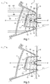
- the figure 1 represents a signaling device 1 according to a first embodiment of the invention, mounted in a lateral housing provided at the front or rear of a vehicle not shown.
- the device 1 is arranged to emit a colored signaling light radiation, in a generally horizontal direction towards the front or rear of the vehicle according to its positioning on the vehicle.
- This signaling device 1 comprises in a housing 2, a filament lamp 3 emitting light rays 4, a reflector 5 of light rays 4, a cover 6 enclosing the lamp 3 and an output screen 7.
- the lamp 3 is here an incandescent bulb type P21W which is mounted on a support plate 8 forming the rear part of the housing 2, its filament being here oriented along the optical axis XX 'of the signaling device 1.
- the output screen 7 which forms the front portion of the housing 2 is made of transparent thermoplastic material, tinted or not, such as polymethylmethacrylate (PMMA).
- PMMA polymethylmethacrylate
- the reflector 5 consists of a frustoconical wall extending flaring at an angle ⁇ with respect to the optical axis X-X ', from the plate 8 (supporting the lamp 3 and forming the rear part of the housing 2 ) to the screen 7.
- the section of the frustoconical wall of the reflector 5 by a plane perpendicular to the optical axis X-X ' has a circular profile.
- this reflector 5 is also made of transparent thermoplastic material tinted or not, such as polymethyl methacrylate (PMMA), its outer face (that directed towards the screen 7) is covered with a reflective alumina coating.
- PMMA polymethyl methacrylate
- the cover 6 which is contained entirely inside the volume defined by the reflector 5, comprises a flat upper wall 6A overhanging the lamp 3 and a cylindrical side wall 6B which surrounds this lamp 3. Just like the screen 7 and the reflector 5, it is also obtained from a transparent thermoplastic material tinted or not, such as polymethylmethacrylate (PMMA).
- PMMA polymethylmethacrylate
- the walls 6A and 6B of this cover 6 are made opaque with a coating which is applied on their outer face, with the exception of certain uncovered portions which constitute passage windows 9, 10, 11, 12 for a part of the light rays 4 emitted by the lamp 3.
- the upper wall 6A thus has a peripheral plane ring 9 not covered, while the side wall 6B has three uncovered cylindrical strips 10, 11, 12, arranged one above the other and evenly distributed over the height of this wall lateral 6B.
- the internal face of the upper wall 6A of the cover 6 has optical means 13 adapted to collimate the light beam 4A which passes through this passage window and to redirect it in a horizontal direction parallel to the optical axis X-X '.
- the side wall 6B of the cover 6 has optical means 14, 15, 16 able to collimate the light beams 4B, 4C, 4D which pass through these windows. and redirecting them towards the reflector 5.
- optical means 14, 15, 16 also makes it possible to modify the striking zones of the light beams 4B, 4C, 4D on the reflector 5, which gives greater freedom of adjustment of the desired pattern in a restricted and constrained environment.
- these optical means are configured so that the beams strike the reflector 5 at an angle of attack substantially equal to the flare angle ⁇ of this reflector 5, so that these beams 4B, 4C, 4D are then reflected. in directions parallel to the optical axis X-X '.
- the optical means here consist of convergent lenses 13, 14, 15, 16 arranged on the internal face of the cover 6.
- the reflector 5 has come integrally molded with the cover 6, which limits the number of parts necessary for the manufacture of the device 1 and thus to reduce the cost.
- This also has the advantage of requiring only a single operation of covering the outer face of the workpiece with a reflective coating by simply previously masking the areas 9, 10, 11, 12 not to cover.
- a portion of the light rays 4 emitted by the lamp 3 passes through the upper wall 6A of the cover 6 at its peripheral ring 9, this light beam 4A being redirected by the optical means 13 to the screen 7 in a direction parallel to the optical axis X-X '.
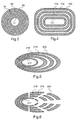
- the beam 4A which then hits this screen 7, is transmitted directly to the space to be illuminated and forms a first central image 17 in the form of a circle. ( figure 2 )
- Another part 4B, 4C, 4D of the light rays emitted by the lamp 3 passes through the side wall 6B of the cover 6 at the level of the three cylindrical strips 10, 11, 12 and is then redirected by the optical means 14, 15, 16 towards the reflector 5.
- the three beams 4B, 4C, 4D reflected by this reflector are offset laterally from one another, so that the generated images 18, 19, 20 form a series of concentric peripheral light circles. with the central image 17 and larger diameters ( figure 2 ). This multitude of light circles included in each other thus gives an optical effect of depth to the light signaling generated by the device 1.
- the cover 6 makes it possible to mask the lamp 3, while presenting through the screen 7, an alumina appearance similar to that of the reflector 5.
- the signaling device 1 'illustrated in this figure is similar to the device 1 described above except that the reflector 5' and the cover 6 'are obtained separately; the side wall 6B 'of the cover 6' being fastened by clipping on the plate 8 'supporting the lamp 3.
- the sections of the side wall of the cover and the frustoconical wall of the reflector by a plane perpendicular to the optical axis XX ' may have non-circular contours.
- these sections may for example have substantially rectangular contours, the central images 117 and peripheral 118, 119, 120 generated then forming a series of concentric light rectangles ( figure 4 ).
- these sections could also have square contours, triangular or even elliptical; the generated images then forming a series of squares, triangles or concentric luminous ellipses.
- the flare angle ⁇ of this frustoconical wall may be more pronounced on one side than the other of the optical axis X-X ', the generated images then forming a series of luminous patterns contained one in the other but not concentric.
- the generated central 217 and peripheral 218, 219, 220 images then form a series of luminous ellipses. contained in each other but not concentric ( figure 5 ).
- the shape of the cover may be different from that illustrated in the figures.
- the latter may also have passage windows for the light rays that are discontinuous on the periphery of the cache.
- the central images 317 and peripheral 318, 319, 320 generated then form a series of discontinuous light patterns ( figure 6 ).
Description
La présente invention concerne un dispositif de signalisation, notamment un feu de position situé à l'arrière ou à l'avant d'un véhicule, qui soit apte à générer un effet de profondeur tridimensionnel.The present invention relates to a signaling device, particularly a position light located at the rear or front of a vehicle, which is capable of generating a three-dimensional depth effect.
La demande européenne
Un réflecteur présentant une surface externe bombée réfléchissante est disposé entre le support et l'écran, ce réflecteur comprenant une série d'orifices disposés au droit des diodes électroluminescentes selon leur axe principal d'éclairage.A reflector having a reflective convex outer surface is disposed between the support and the screen, this reflector comprising a series of orifices arranged in line with the light-emitting diodes along their main illumination axis.
L'écran et le réflecteur forment une cavité délimitée essentiellement par la surface externe réfléchissante du réflecteur et par la surface interne de l'écran.The screen and the reflector form a cavity delimited essentially by the reflective outer surface of the reflector and by the inner surface of the screen.
Les rayons lumineux émis par les diodes électroluminescentes qui traversent les orifices viennent rencontrer la surface interne de l'écran.The light rays emitted by the light-emitting diodes that pass through the orifices meet the inner surface of the screen.
Les rayons frappant la portion transparente de l'écran sont transmis directement vers l'espace à illuminer et forment une première image assurant la fonction de signalisation du dispositif d'un point de vue photométrique.The rays striking the transparent portion of the screen are transmitted directly to the space to be illuminated and form a first image providing the signaling function of the device from a photometric point of view.
Une partie des autres rayons qui frappent la portion semi-réfléchissante de l'écran est transmise par l'écran vers l'espace à illuminer et forme une deuxième image. L'autre partie de ces autres rayons lumineux est réfléchie par l'écran vers la surface externe bombée du réflecteur. Ces rayons sont alors réfléchis par le réflecteur en direction de l'écran. Ceux-ci vont alors être, pour partie transmis par l'écran vers l'espace à illuminer en formant une troisième image et pour partie réfléchis une nouvelle fois par l'écran vers la surface externe bombée du réflecteur, et ainsi de suite de sorte à former une multitude d'images dont l'intensité lumineuse diminue progressivement.Part of the other rays striking the semi-reflective portion of the screen is transmitted by the screen to the space to be illuminated and forms a second image. The other part of these others light rays is reflected by the screen towards the convex outer surface of the reflector. These rays are then reflected by the reflector towards the screen. These will then be partly transmitted by the screen to the space to be illuminated by forming a third image and partly reflected again by the screen to the convex outer surface of the reflector, and so on so to form a multitude of images whose light intensity gradually decreases.
De par la nature bombée du réflecteur, les rayons lumineux réfléchis par le réflecteur se décalent progressivement vers le centre de la cavité, de sorte que les images générées forment une série de rectangles lumineux concentriques donnant un effet optique de profondeur.Due to the convex nature of the reflector, the light rays reflected by the reflector are gradually shifted towards the center of the cavity, so that the generated images form a series of concentric light rectangles giving an optical depth effect.
Toutefois, ce type de dispositif est actuellement réservé aux véhicules automobiles haut de gamme, de par son coût particulièrement élevé, dû notamment au nombre important de diodes électroluminescentes qu'il comporte mais également à la complexité optique de l'écran dont la fabrication nécessite un soin tout particulier.However, this type of device is currently reserved for high-end motor vehicles, because of its particularly high cost, due in particular to the large number of light-emitting diodes that it includes, but also to the optical complexity of the screen, the manufacture of which requires very particular care.
Le document
La présente invention vise donc à proposer un dispositif de signalisation pour véhicule avec effet tridimensionnel qui présente en outre un faible coût de fabrication.The present invention therefore aims to provide a vehicle signaling device with three-dimensional effect which also has a low manufacturing cost.
Elle propose à cet effet un dispositif de signalisation lumineuse pour véhicule automobile avec effet optique tridimentionnel, comportant une lampe à filament montée sur un support, un réflecteur de rayons lumineux, ladite lampe et ledit réflecteur étant disposés derrière un écran de sortie ;
ledit dispositif étant caractérisé en ce que :
- le réflecteur est constitué d'une paroi tronconique s'étendant en s'évasant depuis ledit support en direction dudit écran, et selon un angle d'évasement prédéterminé par rapport à l'axe optique dudit dispositif ;
- ledit dispositif comporte en outre un cache enveloppant ladite lampe, ledit cache étant contenu à l'intérieur du volume défini par la paroi tronconique du réflecteur ;
- ledit cache comportant une paroi latérale présentant une pluralité de fenêtres de passage en forme de bandeau et disposées les unes au dessus des autres, ces fenêtres permettant à des faisceaux correspondants de rayons lumineux émis par ladite lampe de traverser ledit cache et d'être réfléchis vers l'écran de sortie par la paroi tronconique du réflecteur en formant des images lumineuses contenues les unes dans les autres de manière à générer ledit effet visuel tridimentionnel.
said device being characterized in that:
- the reflector consists of a frustoconical wall extending flaring from said support towards said screen, and at a predetermined flare angle with respect to the optical axis of said device;
- said device further comprises a cover enclosing said lamp, said cover being contained within the volume defined by the frustoconical wall of the reflector;
- said cover having a side wall having a plurality of band-shaped passage windows and arranged one above the other, said windows allowing corresponding beams of light rays emitted by said lamp to pass through said cover and be reflected to the exit screen through the frustoconical wall of the reflector forming luminous images contained in each other so as to generate said three-dimensional visual effect.
Le dispositif de signalisation selon l'invention permet ainsi de générer le même type d'effet tridimentionnel que les dispositifs existants à partir d'un système optique simple basé sur l'association d'une lampe à filament, d'un cache muni de fenêtres laissant passer les rayons lumineux et présentant une forme et une disposition particulières, et d'un réflecteur tronconique.The signaling device according to the invention thus makes it possible to generate the same type of three-dimensional effect as the existing devices from a simple optical system based on the combination of a filament lamp, a windowed cover passing light rays and having a particular shape and arrangement, and a frustoconical reflector.
En jouant sur les dimensions et les formes des fenêtres ainsi que sur le contour de la section tronconique du réflecteur, il permet également de créer et d'émettre une grande variété d'effets tridimentionnels lumineux à destination de l'environnement du véhicule.By playing on the dimensions and shapes of the windows as well as on the contour of the frustoconical section of the reflector, it also makes it possible to create and to emit a great variety of luminous three-dimensional effects intended for the environment of the vehicle.
D'autre part, de par sa simplicité, le coût de production d'un tel dispositif est donc particulièrement faible en comparaison des dispositifs actuels et sa mise en oeuvre n'est donc pas limitée aux modèles de véhicules haut de gamme.On the other hand, by its simplicity, the production cost of such a device is particularly low compared to current devices and its implementation is not limited to high-end vehicle models.
Selon des caractéristiques préférées du dispositif, prises seules ou en combinaison :
- ledit cache comporte une paroi supérieure surplombant la lampe et qui présente une fenêtre de passage en forme d'anneau permettant à un faisceau correspondant de rayons lumineux émis par ladite lampe de traverser ledit cache et d'atteindre directement l'écran de sortie en formant une image lumineuse centrale entourée des dites images lumineuses ;
- au niveau de la fenêtre de passage qu'elle comporte, la paroi supérieure du cache présente des moyens optiques aptes à collimater présente des moyens optiques aptes à collimater le faisceau lumineux qui traverse cette fenêtre de passage et à le rediriger selon une direction parallèle à l'axe optique ;
- au niveau de chacune des fenêtres de passage qu'elle comporte, la paroi latérale du cache présente des moyens optiques aptes à collimater les faisceaux lumineux qui traversent ces fenêtres de passage et à les rediriger en direction du réflecteur de telle sorte qu'ils soient ensuite réfléchis en direction de l'écran de sortie ;
- les moyens optiques de la paroi latérale du cache sont configurés pour que lesdits faisceaux frappent le réflecteur selon un angle d'attaque sensiblement égal à l'angle d'évasement de ce réflecteur, de sorte qu'ils soient ensuite réfléchis selon des directions parallèles à l'axe optique ;
- les moyens optiques sont formés par des lentilles convergentes, des lentilles de Fresnel ou bien des stries ;
- le réflecteur est venu de moulage d'une seule pièce avec le cache ;
- ladite pièce est obtenue à partir d'un matériau transparent, teinté ou non, dont la face externe est ensuite recouverte d'un revêtement réfléchissant, à l'exception de certaines portions non recouvertes qui forment lesdites fenêtres de passage pour une partie des rayons lumineux émis par la lampe ;
- la section de la paroi tronconique du réflecteur par un plan perpendiculaire à l'axe optique, présente un profil circulaire, carré, triangulaire, ou bien encore elliptique ; et/ou
- lesdites fenêtres de passage sont discontinues sur la périphérie du cache.
- said cover has an upper wall overhanging the lamp and which has a ring-shaped passage window allowing a corresponding beam of light rays emitted by said lamp to pass through said cover and to reach directly the output screen forming a central luminous image surrounded by so-called luminous images;
- at the level of the passage window that it comprises, the upper wall of the cover has optical means able to collimate present optical means able to collimate the light beam which passes through this passage window and to redirect it in a direction parallel to the optical axis;
- at the level of each of the passage windows that it comprises, the side wall of the cover has optical means able to collimate the light beams passing through these passage windows and to redirect them towards the reflector so that they are then reflect towards the exit screen;
- the optical means of the side wall of the cover are configured so that said beams strike the reflector at an angle of attack substantially equal to the flare angle of this reflector, so that they are then reflected in directions parallel to the optical axis;
- the optical means are formed by convergent lenses, Fresnel lenses or streaks;
- the reflector came from molding in one piece with the cover;
- said piece is obtained from a transparent material, tinted or not, the outer face of which is then covered with a reflective coating, with the exception of certain uncovered portions which form said passage windows for part of the light rays emitted by the lamp;
- the section of the frustoconical wall of the reflector by a plane perpendicular to the optical axis, has a circular profile, square, triangular, or even elliptical; and or
- said passage windows are discontinuous on the periphery of the cache.
L'exposé de l'invention sera maintenant poursuivi par la description détaillée d'un exemple de réalisation, donnée ci-après à titre illustratif mais non limitatif, en référence aux dessins annexés, sur lesquels :
- la
figure 1 est une représentation schématique en coupe verticale du dispositif de signalisation selon un premier de réalisation de l'invention ; - la
figure 2 représente une vue en élévation du dispositif de lafigure 1 lorsqu'il est sous tension, illustrant l'aspect éclairé de ce dispositif et l'effet optique tridimensionnel ; - la
figure 3 est une représentation schématique en coupe verticale du dispositif de signalisation selon une variante du mode de réalisation illustré par lafigure 1 ; et - les
figures 4 à 6 illustrent des alternatives d'aspect éclairé pouvant être obtenues avec certaines variantes du dispositif selon l'invention.
- the
figure 1 is a schematic representation in vertical section of the signaling device according to a first embodiment of the invention; - the
figure 2 represents an elevational view of the device of thefigure 1 when energized, illustrating the illuminated aspect of this device and the three-dimensional optical effect; - the
figure 3 is a schematic representation in vertical section of the signaling device according to a variant of the embodiment illustrated by FIG.figure 1 ; and - the
Figures 4 to 6 illustrate alternatives of enlightened appearance that can be obtained with certain variants of the device according to the invention.
La
Le dispositif 1 est disposé de sorte à émettre un rayonnement lumineux de signalisation coloré, selon une direction globalement horizontale vers l'avant ou vers l'arrière du véhicule selon son positionnement sur le véhicule.The device 1 is arranged to emit a colored signaling light radiation, in a generally horizontal direction towards the front or rear of the vehicle according to its positioning on the vehicle.
Ce dispositif de signalisation 1 comporte dans un boîtier 2, une lampe à filament 3 émettant des rayons lumineux 4, un réflecteur 5 de rayons lumineux 4, un cache 6 enveloppant la lampe 3 et un écran de sortie 7.This signaling device 1 comprises in a
La lampe 3 est ici une ampoule à incandescence de type P21W qui est montée sur une platine support 8 formant la partie arrière du boîtier 2, son filament étant ici orienté selon l'axe optique X-X' du dispositif de signalisation 1.The
L'écran de sortie 7 qui forme la partie avant du boîtier 2, est réalisé en matériau thermoplastique transparent, teinté ou non, tel que le polyméthacrylate de méthyle (PMMA).The
Le réflecteur 5 est constitué d'une paroi tronconique s'étendant en s'évasant selon un angle α par rapport à l'axe optique X-X', depuis la platine 8 (supportant la lampe 3 et formant la partie arrière du boîtier 2) jusqu'à l'écran 7. D'autre part, la section de la paroi tronconique du réflecteur 5 par un plan perpendiculaire à l'axe optique X-X', présente un profil circulaire.The
De préférence, ce réflecteur 5 est également réalisé en matériau thermoplastique transparent teinté ou non, tel que le polyméthacrylate de méthyle (PMMA), sa face extérieure (celle orientée en direction de l'écran 7) étant recouverte d'un revêtement réfléchissant aluminé.Preferably, this
Le cache 6 qui est contenu intégralement à l'intérieur du volume défini par le réflecteur 5, comporte une paroi supérieure plane 6A surplombant la lampe 3 et une paroi latérale cylindrique 6B qui entoure cette lampe 3. Tout comme l'écran 7 et le réflecteur 5, il est obtenu également à partir d'un matériau thermoplastique transparent teinté ou non, tel que le polyméthacrylate de méthyle (PMMA).The
Les parois 6A et 6B de ce cache 6 sont rendues opaques à l'aide d'un revêtement qui est appliqué sur leur face extérieure, à l'exception de certaines portions non recouvertes qui constituent des fenêtres de passage 9, 10, 11, 12 pour une partie des rayons lumineux 4 émis par la lampe 3.The
La paroi supérieure 6A présente ainsi un anneau plan périphérique 9 non recouvert, tandis que la paroi latérale 6B présente trois bandeaux cylindriques 10, 11, 12 non recouverts, disposés les uns aux dessus des autres et répartis de manière régulière sur la hauteur de cette paroi latérale 6B.The upper wall 6A thus has a
Au niveau de la fenêtre de passage 9, la face interne de la paroi supérieure 6A du cache 6 présente des moyens optiques 13 adapté à collimater le faisceau lumineux 4A qui traverse cette fenêtre de passage et à le rediriger selon une direction horizontale parallèle à l'axe optique X-X'.At the level of the
De même, au niveau de chacune des fenêtres de passage 10, 11, 12, la paroi latérale 6B du cache 6 présente des moyens optiques 14, 15, 16 aptes à collimater les faisceaux lumineux 4B, 4C, 4D qui traversent ces fenêtres de passage et à les rediriger en direction du réflecteur 5.Similarly, at each of the
La présence des moyens optiques 14, 15, 16 permet également de modifier les zones de frappe des faisceaux lumineux 4B, 4C, 4D sur le réflecteur 5, ce qui apporte une plus grande liberté de réglage du motif souhaité dans un environnement restreint et contraint.The presence of the optical means 14, 15, 16 also makes it possible to modify the striking zones of the
De préférence, ces moyens optiques sont configurés pour que les faisceaux frappent le réflecteur 5 selon un angle d'attaque sensiblement égal à l'angle d'évasement α de ce réflecteur 5, de sorte que ces faisceaux 4B, 4C, 4D soient ensuite réfléchis selon des directions parallèles à l'axe optique X-X'.Preferably, these optical means are configured so that the beams strike the
Les moyens optiques sont ici constitués par des lentilles convergentes 13, 14, 15, 16 disposées sur la face interne du cache 6.The optical means here consist of
De préférence et comme illustré sur la
Cela présente également l'avantage de ne nécessiter qu'une seule opération de recouvrement de la face extérieure de la pièce par un revêtement réfléchissant en masquant simplement au préalable les zones 9, 10, 11, 12 à ne pas recouvrir.This also has the advantage of requiring only a single operation of covering the outer face of the workpiece with a reflective coating by simply previously masking the
On va maintenant décrire rapidement le fonctionnement du dispositif de signalisation 1 lorsque la lampe 3 est allumée à l'appui des
Une partie des rayons lumineux 4 émis par la lampe 3 traverse la paroi supérieure 6A du cache 6 au niveau de son anneau périphérique 9, ce faisceau lumineux 4A étant redirigé par les moyens optiques 13 vers l'écran 7 selon une direction parallèle à l'axe optique X-X'.A portion of the
Le faisceau 4A qui vient ensuite frapper cet écran 7, est transmis directement vers l'espace à illuminer et forme une première image centrale 17 en forme de cercle. (
Une autre partie 4B, 4C, 4D des rayons lumineux émis par la lampe 3 traverse la paroi latérale 6B du cache 6 au niveau des trois bandeaux cylindriques 10, 11, 12 puis est redirigée par les moyens optiques 14, 15, 16 vers le réflecteur 5.Another
Ces faisceaux 4B, 4C, 4D sont ensuite presque totalement réfléchis par la face extérieure réfléchissante de ce réflecteur vers l'écran 7 selon des directions parallèles à l'axe optique.These
Les rayons constituant ces faisceaux 4B, 4C, 4D sont transmis directement vers l'espace à illuminer par l'écran 7 et forment trois d'images périphériques 18, 19, 20 dont l'intensité lumineuse est proche de celle de la première image (
De par la forme tronconique du réflecteur, les trois faisceaux 4B, 4C, 4D réfléchis par ce réflecteur sont décalés latéralement l'un de l'autre, de sorte que les images générées 18, 19, 20 forment une série de cercles lumineux périphériques concentriques avec l'image centrale 17 et de plus grands diamètres (
En outre, lorsque la lampe 3 du dispositif 1 est éteinte, le cache 6 permet de masquer cette lampe 3, tout en présentant au travers de l'écran 7, un aspect aluminé semblable à celui du réflecteur 5.In addition, when the
On va maintenant décrire rapidement une variante de réalisation du dispositif selon l'invention à l'appui de la
Le dispositif de signalisation 1' illustré sur cette figure est semblable au dispositif 1 décrit précédemment si ce n'est que le réflecteur 5' et le cache 6' sont obtenus séparément ; la paroi latérale 6B' du cache 6' étant fixé par enclipsage sur la platine 8' supportant la lampe 3.The signaling device 1 'illustrated in this figure is similar to the device 1 described above except that the reflector 5' and the
De manière générale et afin d'obtenir des rendus tridimensionnels différents, les sections de la paroi latérale du cache et de la paroi tronconique du réflecteur par un plan perpendiculaire à l'axe optique X-X' peuvent présenter des contours non circulaires.In general and in order to obtain different three-dimensional renderings, the sections of the side wall of the cover and the frustoconical wall of the reflector by a plane perpendicular to the optical axis XX 'may have non-circular contours.
Ainsi, ces sections peuvent par exemple présenter des contours sensiblement rectangulaires, les images centrale 117 et périphériques 118, 119, 120 générées formant alors une série de rectangles lumineux concentriques (
Selon d'autres variantes non représentées, ces sections pourraient également présenter des contours carrés, triangulaires, ou bien encore elliptiques ; les images générées formant alors une série de carrés, de triangles ou bien d'ellipses lumineux concentriques.According to other variants not shown, these sections could also have square contours, triangular or even elliptical; the generated images then forming a series of squares, triangles or concentric luminous ellipses.
D'autre part, l'angle d'évasement α de cette paroi tronconique peut être plus prononcé d'un côté que de l'autre de l'axe optique X-X', les images générées formant alors une série de motifs lumineux contenus l'un dans l'autre mais non concentriques. Ainsi, dans le cas d'une telle paroi tronconique dont la section par un plan perpendiculaire à l'axe optique X-X' présente un contour elliptique, les images centrale 217 et périphériques 218, 219, 220 générées forment alors une série d'ellipses lumineuses contenues les unes dans les autres mais non concentriques (
De manière générale, la forme du cache peut être différente de celle illustrée sur les figures. Ce dernier peut également présenter des fenêtres de passage pour les rayons lumineux qui soient discontinues sur la périphérie du cache. Dans un tel cas de figure, les images centrale 317 et périphériques 318, 319, 320 générées forment alors une série de motifs lumineux discontinus (
Selon encore d'autres variantes de réalisation non représentées :
- seule la paroi latérale du cache présente des fenêtres de passage pour les rayons lumineux, de sorte que l'image centrale n'est pas générée ;
- les lentilles convergentes sont disposées sur la face externe du cache ;
- le cache ne comporte pas de moyens optiques ou ces derniers sont différents, par exemple constitués de lentilles de Fresnel ou de stries convergentes ;
- la lampe à filament est d'un type différent, par exemple une lampe halogène ;
- le filament de la lampe est orienté selon une direction transversale à l'axe optique du dispositif ; et/ou
- le cache est rendu opaque à l'aide d'une peinture de couleur neutre, mate ou métallisée.
- only the side wall of the cover has passing windows for the light rays, so that the central image is not generated;
- the convergent lenses are arranged on the outer face of the cover;
- the cover has no optical means or the latter are different, for example made of Fresnel lenses or convergent striations;
- the filament lamp is of a different type, for example a halogen lamp;
- the filament of the lamp is oriented in a direction transverse to the optical axis of the device; and or
- the cover is made opaque with a neutral, matte or metallic paint.
Bien entendu, la présente invention ne se limite pas aux formes de réalisation décrites et représentées, mais elle englobe toute autre variante d'exécution.Of course, the present invention is not limited to the embodiments described and shown, but encompasses any other embodiment.
Claims (10)
- A vehicle light signalling device with three-dimensional optical effect, comprising a filament lamp (3) mounted on a support (8; 8'), a reflector (5; 5') of light rays (4), said lamp (3) and said reflector (5; 5') being disposed behind an outlet screen (7);
said device being characterized in that:- the reflector (5; 5') is constituted by a frustoconical wall, widening, from said support (8; 8') in the direction of said screen (7), and at a predetermined flare angle (α) with respect to the optical axis (X-X') of said device;- said device further comprises a shield (6; 6') enveloping said lamp (3), said shield (6; 6') being contained in the interior of the volume defined by the frustoconical wall of the reflector (5; 5');- said shield (6' 6') comprising a lateral wall (6B; 6B') having a plurality of strip-shaped through-openings (10, 11, 12) and arranged one above the next, these openings allowing corresponding beams (4B, 4C, 4D) of rays of light (4) emitted by said lamp (3) to pass through said shield (6; 6') and to be reflected towards the outlet screen (7) by the frustoconical wall of the reflector (5), forming light images (18, 19, 20; 118, 119, 120; 218, 219, 220; 318, 319, 320) contained inside one another in such a way as to generate said three-dimensional visual effect. - The light signalling device according to Claim 1, characterized in that said shield (6; 6') comprises an upper wall (6A) overhanging the lamp (3) and which has a ring-shaped through-opening (9) permitting a corresponding beam (4A) of light rays (4) emitted by said lamp (3) to pass through said shield (6; 6') and to directly reach the outlet screen (7), forming a central light image (17; 117; 217; 317) surrounded by said light images (18, 19, 20; 118, 119, 120; 218, 219, 220; 318, 319, 320).
- The light signalling device according to Claim 2, characterized in that, at the level of the through-opening (9) which it comprises, the upper wall (6A) of the shield (6; 6') has optical means (13) able to focus the light beam (4A) which passes through this through-opening (9) and to redirect it along a direction parallel to the optical axis (X-X').
- The light signalling device according to one of Claims 1 to 3, characterized in that, at the level of each of the through-openings (10, 11, 12) which it comprises, the lateral wall (6B, 6B') of the shield (6; 6') has optical means (14, 15, 16) able to focus the light beams (4B, 4C, 4D) which pass through these through-openings (10, 11, 12) and to redirect them in the direction of the reflector (5) such that they are then reflected in the direction of the outlet screen (7).
- The light signalling device according to Claim 4, characterized in that the optical means (14, 15, 16) of the lateral wall (6B; 6B') of the shield (6; 6') are configured so that said beams (4B, 4C, 4D) strike the reflector (5; 5') at an angle of attack substantially equal to the flare angle (α) of this reflector (5; 5'), in such a manner that they are then reflected along directions parallel to the optical axis (X-X').
- The light signalling device according to one of Claims 3 to 5, characterized in that the optical means (13, 14, 15, 16) are formed by convergent lenses, Fresnel lenses or else striations.
- The light signalling device according to one of Claims 1 to 6, characterized in that the reflector (5) is moulded in a single piece with the shield (6).
- The light signalling device according to Claim 7, characterized in that said piece is obtained from a transparent material, tinted or not, the external face of which is then covered by a reflecting coating, with the exception of certain portions which are not covered, which form said through-openings (9, 10, 11, 12) for a portion of the light rays (4) emitted by the lamp (3).
- The light signalling device according to one of Claims 1 to 8, characterized in that the section of the frustoconical wall of the reflector (5; 5') through a plane perpendicular to the optical axis (X-X') has a circular, square, triangular or else elliptical profile.
- The light signalling device according to one of Claims 1 to 9, characterized in that said through-openings (9, 10, 11, 12) are discontinuous over the periphery of the shield (6; 6').
Applications Claiming Priority (2)
| Application Number | Priority Date | Filing Date | Title |
|---|---|---|---|
| FR1261323A FR2998644B1 (en) | 2012-11-28 | 2012-11-28 | SIGNALING DEVICE FOR VEHICLE WITH THREE DIMENSIONAL EFFECT |
| PCT/FR2013/052787 WO2014083262A1 (en) | 2012-11-28 | 2013-11-19 | Vehicle signalling device with three-dimensional effect |
Publications (2)
| Publication Number | Publication Date |
|---|---|
| EP2926049A1 EP2926049A1 (en) | 2015-10-07 |
| EP2926049B1 true EP2926049B1 (en) | 2016-10-12 |
Family
ID=47628242
Family Applications (1)
| Application Number | Title | Priority Date | Filing Date |
|---|---|---|---|
| EP13815038.8A Not-in-force EP2926049B1 (en) | 2012-11-28 | 2013-11-19 | Vehicle signalling device with three-dimensional effect |
Country Status (4)
| Country | Link |
|---|---|
| EP (1) | EP2926049B1 (en) |
| CN (1) | CN104797880B (en) |
| FR (1) | FR2998644B1 (en) |
| WO (1) | WO2014083262A1 (en) |
Families Citing this family (4)
| Publication number | Priority date | Publication date | Assignee | Title |
|---|---|---|---|---|
| CN108119870A (en) * | 2017-11-29 | 2018-06-05 | 马瑞利汽车零部件(芜湖)有限公司 | A kind of method for the automobile signal light for realizing shutter effect |
| CN109611788A (en) * | 2019-01-24 | 2019-04-12 | 华域视觉科技(上海)有限公司 | Three-dimensional optical component, lamps and lanterns and the method for generating three dimensional depth illumination effect |
| PL430271A1 (en) * | 2019-06-17 | 2020-12-28 | Przetwórstwo Tworzyw Sztucznych Waś Józef I Leszek Waś Spółka Jawna | Rear lamp for a wheeled vehicle |
| JP7423300B2 (en) * | 2019-12-19 | 2024-01-29 | スタンレー電気株式会社 | Vehicle lights |
Family Cites Families (6)
| Publication number | Priority date | Publication date | Assignee | Title |
|---|---|---|---|---|
| FR2476798A1 (en) * | 1980-02-25 | 1981-08-28 | Cibie Projecteurs | FIRE, IN PARTICULAR FOR THE SIGNALING OF MOTOR VEHICLES |
| JP3607019B2 (en) * | 1996-10-17 | 2005-01-05 | 株式会社小糸製作所 | Vehicle lamp |
| JPH11265606A (en) * | 1998-03-18 | 1999-09-28 | Koito Mfg Co Ltd | Marker lamp for vehicle |
| CN101187457A (en) * | 2006-10-24 | 2008-05-28 | 瓦莱奥.西尔瓦尼亚有限责任公司 | Three dimensional effect lamp assembly |
| JP5596418B2 (en) * | 2010-06-01 | 2014-09-24 | 株式会社小糸製作所 | Vehicle lighting |
| DE102010049422A1 (en) * | 2010-10-23 | 2012-04-26 | Automotive Lighting Reutlingen Gmbh | Lighting device for a motor vehicle |
-
2012
- 2012-11-28 FR FR1261323A patent/FR2998644B1/en not_active Expired - Fee Related
-
2013
- 2013-11-19 EP EP13815038.8A patent/EP2926049B1/en not_active Not-in-force
- 2013-11-19 CN CN201380059918.7A patent/CN104797880B/en not_active Expired - Fee Related
- 2013-11-19 WO PCT/FR2013/052787 patent/WO2014083262A1/en active Application Filing
Also Published As
| Publication number | Publication date |
|---|---|
| CN104797880B (en) | 2018-09-21 |
| EP2926049A1 (en) | 2015-10-07 |
| WO2014083262A1 (en) | 2014-06-05 |
| FR2998644B1 (en) | 2015-01-16 |
| FR2998644A1 (en) | 2014-05-30 |
| CN104797880A (en) | 2015-07-22 |
Similar Documents
| Publication | Publication Date | Title |
|---|---|---|
| EP1288562B1 (en) | Lighting or signalling device for motor vehicle | |
| EP2098774B1 (en) | Optical system with main function for an automobile | |
| EP1746339B1 (en) | Device for lighting or signalising, in particular for vehicles | |
| EP1434000B1 (en) | LIghting and/or signalling device for motor vehicles | |
| EP3390900B1 (en) | Light module, in particular for vehicle stop light | |
| FR2973476A1 (en) | OPTICAL SYSTEM FOR GENERATING A COMPOSITE LARGE BEAM OF LARGE ANGULAR OPENING | |
| FR2851030A1 (en) | VEHICLE HEADLIGHT WITH SOURCE, REFLECTOR AND LENS | |
| FR3050011A1 (en) | MODULE FOR TRANSMITTING A LUMINOUS BEAM FOR MOTOR VEHICLE PROJECTOR | |
| EP2317214A1 (en) | Lighting or signalling device for an automobile comprising a light guide | |
| WO2019158889A1 (en) | Signaling device for a motor vehicle | |
| EP2926049B1 (en) | Vehicle signalling device with three-dimensional effect | |
| EP2846081B1 (en) | Lighting and signalling device of a vehicle | |
| EP3190335B1 (en) | Luminous device provided with a curved wavelength conversion element, and headlight comprising such a luminous device | |
| WO2017121944A1 (en) | Optical unit including a signaling light having a flat light guide projecting from the outer lens | |
| EP3354977A1 (en) | Lighting device with light guide mounted on a supporting part incorporating a transparent magnification screen | |
| FR3032514A1 (en) | LUMINOUS MODULE OF A VEHICLE COMPATIBLE TO LEFT TRAFFIC AND RIGHT TRAFFIC | |
| FR2939868A1 (en) | Optical system for head light or signaling light of motor vehicle, has light source propagated in single diffusion screen, and insulating separating film separating functions for realization of multiple main optical functions through screen | |
| EP3453955B1 (en) | Light-emitting module for lighting and/or signalling of a motor vehicle | |
| EP1488954B1 (en) | Lighting or signaling system for automotive vehicle | |
| EP1489351B1 (en) | Vehicle headlight with at least two functions | |
| EP3898332B1 (en) | Lighting device for a vehicle ceiling lamp | |
| EP2853804B1 (en) | Lighting and/or signalling module with a plurality of rotary optical systems | |
| EP3124856A1 (en) | Lighting device for a motor vehicle | |
| EP3728939A1 (en) | Light signalling device for motor vehicle offering improved visual comfort to road users | |
| FR2912806A1 (en) | Headlight e.g. turn signal lamp, for motor vehicle, has individual headlights co-operating for forming global light distribution, where additional optic of each individual headlight is associated with each LED of each individual headlight |
Legal Events
| Date | Code | Title | Description |
|---|---|---|---|
| PUAI | Public reference made under article 153(3) epc to a published international application that has entered the european phase |
Free format text: ORIGINAL CODE: 0009012 |
|
| 17P | Request for examination filed |
Effective date: 20150529 |
|
| AK | Designated contracting states |
Kind code of ref document: A1 Designated state(s): AL AT BE BG CH CY CZ DE DK EE ES FI FR GB GR HR HU IE IS IT LI LT LU LV MC MK MT NL NO PL PT RO RS SE SI SK SM TR |
|
| AX | Request for extension of the european patent |
Extension state: BA ME |
|
| DAX | Request for extension of the european patent (deleted) | ||
| GRAP | Despatch of communication of intention to grant a patent |
Free format text: ORIGINAL CODE: EPIDOSNIGR1 |
|
| INTG | Intention to grant announced |
Effective date: 20160518 |
|
| GRAS | Grant fee paid |
Free format text: ORIGINAL CODE: EPIDOSNIGR3 |
|
| GRAA | (expected) grant |
Free format text: ORIGINAL CODE: 0009210 |
|
| AK | Designated contracting states |
Kind code of ref document: B1 Designated state(s): AL AT BE BG CH CY CZ DE DK EE ES FI FR GB GR HR HU IE IS IT LI LT LU LV MC MK MT NL NO PL PT RO RS SE SI SK SM TR |
|
| REG | Reference to a national code |
Ref country code: GB Ref legal event code: FG4D Free format text: NOT ENGLISH |
|
| REG | Reference to a national code |
Ref country code: CH Ref legal event code: EP |
|
| REG | Reference to a national code |
Ref country code: AT Ref legal event code: REF Ref document number: 836852 Country of ref document: AT Kind code of ref document: T Effective date: 20161015 |
|
| REG | Reference to a national code |
Ref country code: FR Ref legal event code: PLFP Year of fee payment: 4 |
|
| REG | Reference to a national code |
Ref country code: IE Ref legal event code: FG4D Free format text: LANGUAGE OF EP DOCUMENT: FRENCH |
|
| REG | Reference to a national code |
Ref country code: DE Ref legal event code: R096 Ref document number: 602013012818 Country of ref document: DE |
|
| REG | Reference to a national code |
Ref country code: DE Ref legal event code: R084 Ref document number: 602013012818 Country of ref document: DE |
|
| REG | Reference to a national code |
Ref country code: LT Ref legal event code: MG4D |
|
| REG | Reference to a national code |
Ref country code: NL Ref legal event code: MP Effective date: 20161012 |
|
| PG25 | Lapsed in a contracting state [announced via postgrant information from national office to epo] |
Ref country code: LV Free format text: LAPSE BECAUSE OF FAILURE TO SUBMIT A TRANSLATION OF THE DESCRIPTION OR TO PAY THE FEE WITHIN THE PRESCRIBED TIME-LIMIT Effective date: 20161012 Ref country code: BE Free format text: LAPSE BECAUSE OF NON-PAYMENT OF DUE FEES Effective date: 20161130 |
|
| REG | Reference to a national code |
Ref country code: AT Ref legal event code: MK05 Ref document number: 836852 Country of ref document: AT Kind code of ref document: T Effective date: 20161012 |
|
| PG25 | Lapsed in a contracting state [announced via postgrant information from national office to epo] |
Ref country code: SE Free format text: LAPSE BECAUSE OF FAILURE TO SUBMIT A TRANSLATION OF THE DESCRIPTION OR TO PAY THE FEE WITHIN THE PRESCRIBED TIME-LIMIT Effective date: 20161012 Ref country code: GR Free format text: LAPSE BECAUSE OF FAILURE TO SUBMIT A TRANSLATION OF THE DESCRIPTION OR TO PAY THE FEE WITHIN THE PRESCRIBED TIME-LIMIT Effective date: 20170113 Ref country code: LT Free format text: LAPSE BECAUSE OF FAILURE TO SUBMIT A TRANSLATION OF THE DESCRIPTION OR TO PAY THE FEE WITHIN THE PRESCRIBED TIME-LIMIT Effective date: 20161012 Ref country code: NO Free format text: LAPSE BECAUSE OF FAILURE TO SUBMIT A TRANSLATION OF THE DESCRIPTION OR TO PAY THE FEE WITHIN THE PRESCRIBED TIME-LIMIT Effective date: 20170112 |
|
| PG25 | Lapsed in a contracting state [announced via postgrant information from national office to epo] |
Ref country code: PT Free format text: LAPSE BECAUSE OF FAILURE TO SUBMIT A TRANSLATION OF THE DESCRIPTION OR TO PAY THE FEE WITHIN THE PRESCRIBED TIME-LIMIT Effective date: 20170213 Ref country code: RS Free format text: LAPSE BECAUSE OF FAILURE TO SUBMIT A TRANSLATION OF THE DESCRIPTION OR TO PAY THE FEE WITHIN THE PRESCRIBED TIME-LIMIT Effective date: 20161012 Ref country code: ES Free format text: LAPSE BECAUSE OF FAILURE TO SUBMIT A TRANSLATION OF THE DESCRIPTION OR TO PAY THE FEE WITHIN THE PRESCRIBED TIME-LIMIT Effective date: 20161012 Ref country code: PL Free format text: LAPSE BECAUSE OF FAILURE TO SUBMIT A TRANSLATION OF THE DESCRIPTION OR TO PAY THE FEE WITHIN THE PRESCRIBED TIME-LIMIT Effective date: 20161012 Ref country code: HR Free format text: LAPSE BECAUSE OF FAILURE TO SUBMIT A TRANSLATION OF THE DESCRIPTION OR TO PAY THE FEE WITHIN THE PRESCRIBED TIME-LIMIT Effective date: 20161012 Ref country code: IS Free format text: LAPSE BECAUSE OF FAILURE TO SUBMIT A TRANSLATION OF THE DESCRIPTION OR TO PAY THE FEE WITHIN THE PRESCRIBED TIME-LIMIT Effective date: 20170212 Ref country code: FI Free format text: LAPSE BECAUSE OF FAILURE TO SUBMIT A TRANSLATION OF THE DESCRIPTION OR TO PAY THE FEE WITHIN THE PRESCRIBED TIME-LIMIT Effective date: 20161012 Ref country code: AT Free format text: LAPSE BECAUSE OF FAILURE TO SUBMIT A TRANSLATION OF THE DESCRIPTION OR TO PAY THE FEE WITHIN THE PRESCRIBED TIME-LIMIT Effective date: 20161012 Ref country code: NL Free format text: LAPSE BECAUSE OF FAILURE TO SUBMIT A TRANSLATION OF THE DESCRIPTION OR TO PAY THE FEE WITHIN THE PRESCRIBED TIME-LIMIT Effective date: 20161012 |
|
| REG | Reference to a national code |
Ref country code: CH Ref legal event code: PL |
|
| REG | Reference to a national code |
Ref country code: DE Ref legal event code: R097 Ref document number: 602013012818 Country of ref document: DE |
|
| REG | Reference to a national code |
Ref country code: GB Ref legal event code: 746 Effective date: 20170703 |
|
| PG25 | Lapsed in a contracting state [announced via postgrant information from national office to epo] |
Ref country code: LI Free format text: LAPSE BECAUSE OF NON-PAYMENT OF DUE FEES Effective date: 20161130 Ref country code: CH Free format text: LAPSE BECAUSE OF NON-PAYMENT OF DUE FEES Effective date: 20161130 Ref country code: CZ Free format text: LAPSE BECAUSE OF FAILURE TO SUBMIT A TRANSLATION OF THE DESCRIPTION OR TO PAY THE FEE WITHIN THE PRESCRIBED TIME-LIMIT Effective date: 20161012 Ref country code: MC Free format text: LAPSE BECAUSE OF FAILURE TO SUBMIT A TRANSLATION OF THE DESCRIPTION OR TO PAY THE FEE WITHIN THE PRESCRIBED TIME-LIMIT Effective date: 20161012 Ref country code: RO Free format text: LAPSE BECAUSE OF FAILURE TO SUBMIT A TRANSLATION OF THE DESCRIPTION OR TO PAY THE FEE WITHIN THE PRESCRIBED TIME-LIMIT Effective date: 20161012 Ref country code: SK Free format text: LAPSE BECAUSE OF FAILURE TO SUBMIT A TRANSLATION OF THE DESCRIPTION OR TO PAY THE FEE WITHIN THE PRESCRIBED TIME-LIMIT Effective date: 20161012 Ref country code: DK Free format text: LAPSE BECAUSE OF FAILURE TO SUBMIT A TRANSLATION OF THE DESCRIPTION OR TO PAY THE FEE WITHIN THE PRESCRIBED TIME-LIMIT Effective date: 20161012 Ref country code: EE Free format text: LAPSE BECAUSE OF FAILURE TO SUBMIT A TRANSLATION OF THE DESCRIPTION OR TO PAY THE FEE WITHIN THE PRESCRIBED TIME-LIMIT Effective date: 20161012 |
|
| PLBE | No opposition filed within time limit |
Free format text: ORIGINAL CODE: 0009261 |
|
| STAA | Information on the status of an ep patent application or granted ep patent |
Free format text: STATUS: NO OPPOSITION FILED WITHIN TIME LIMIT |
|
| REG | Reference to a national code |
Ref country code: IE Ref legal event code: MM4A |
|
| RAP2 | Party data changed (patent owner data changed or rights of a patent transferred) |
Owner name: PSA AUTOMOBILES SA |
|
| PG25 | Lapsed in a contracting state [announced via postgrant information from national office to epo] |
Ref country code: IT Free format text: LAPSE BECAUSE OF FAILURE TO SUBMIT A TRANSLATION OF THE DESCRIPTION OR TO PAY THE FEE WITHIN THE PRESCRIBED TIME-LIMIT Effective date: 20161012 Ref country code: BG Free format text: LAPSE BECAUSE OF FAILURE TO SUBMIT A TRANSLATION OF THE DESCRIPTION OR TO PAY THE FEE WITHIN THE PRESCRIBED TIME-LIMIT Effective date: 20170112 Ref country code: SM Free format text: LAPSE BECAUSE OF FAILURE TO SUBMIT A TRANSLATION OF THE DESCRIPTION OR TO PAY THE FEE WITHIN THE PRESCRIBED TIME-LIMIT Effective date: 20161012 |
|
| 26N | No opposition filed |
Effective date: 20170713 |
|
| PG25 | Lapsed in a contracting state [announced via postgrant information from national office to epo] |
Ref country code: LU Free format text: LAPSE BECAUSE OF NON-PAYMENT OF DUE FEES Effective date: 20161130 |
|
| REG | Reference to a national code |
Ref country code: FR Ref legal event code: PLFP Year of fee payment: 5 |
|
| REG | Reference to a national code |
Ref country code: DE Ref legal event code: R079 Ref document number: 602013012818 Country of ref document: DE Free format text: PREVIOUS MAIN CLASS: F21S0008100000 Ipc: F21S0043000000 |
|
| PG25 | Lapsed in a contracting state [announced via postgrant information from national office to epo] |
Ref country code: IE Free format text: LAPSE BECAUSE OF NON-PAYMENT OF DUE FEES Effective date: 20161119 Ref country code: SI Free format text: LAPSE BECAUSE OF FAILURE TO SUBMIT A TRANSLATION OF THE DESCRIPTION OR TO PAY THE FEE WITHIN THE PRESCRIBED TIME-LIMIT Effective date: 20161012 |
|
| REG | Reference to a national code |
Ref country code: BE Ref legal event code: MM Effective date: 20161130 |
|
| PG25 | Lapsed in a contracting state [announced via postgrant information from national office to epo] |
Ref country code: HU Free format text: LAPSE BECAUSE OF FAILURE TO SUBMIT A TRANSLATION OF THE DESCRIPTION OR TO PAY THE FEE WITHIN THE PRESCRIBED TIME-LIMIT; INVALID AB INITIO Effective date: 20131119 |
|
| PG25 | Lapsed in a contracting state [announced via postgrant information from national office to epo] |
Ref country code: MK Free format text: LAPSE BECAUSE OF FAILURE TO SUBMIT A TRANSLATION OF THE DESCRIPTION OR TO PAY THE FEE WITHIN THE PRESCRIBED TIME-LIMIT Effective date: 20161012 Ref country code: CY Free format text: LAPSE BECAUSE OF FAILURE TO SUBMIT A TRANSLATION OF THE DESCRIPTION OR TO PAY THE FEE WITHIN THE PRESCRIBED TIME-LIMIT Effective date: 20161012 |
|
| REG | Reference to a national code |
Ref country code: FR Ref legal event code: CA Effective date: 20180312 Ref country code: FR Ref legal event code: CD Owner name: PEUGEOT CITROEN AUTOMOBILES SA, FR Effective date: 20180312 |
|
| PG25 | Lapsed in a contracting state [announced via postgrant information from national office to epo] |
Ref country code: MT Free format text: LAPSE BECAUSE OF FAILURE TO SUBMIT A TRANSLATION OF THE DESCRIPTION OR TO PAY THE FEE WITHIN THE PRESCRIBED TIME-LIMIT Effective date: 20161012 |
|
| REG | Reference to a national code |
Ref country code: FR Ref legal event code: PLFP Year of fee payment: 6 |
|
| PG25 | Lapsed in a contracting state [announced via postgrant information from national office to epo] |
Ref country code: TR Free format text: LAPSE BECAUSE OF FAILURE TO SUBMIT A TRANSLATION OF THE DESCRIPTION OR TO PAY THE FEE WITHIN THE PRESCRIBED TIME-LIMIT Effective date: 20161012 |
|
| PGFP | Annual fee paid to national office [announced via postgrant information from national office to epo] |
Ref country code: DE Payment date: 20191021 Year of fee payment: 7 |
|
| PGFP | Annual fee paid to national office [announced via postgrant information from national office to epo] |
Ref country code: FR Payment date: 20191022 Year of fee payment: 7 |
|
| PGFP | Annual fee paid to national office [announced via postgrant information from national office to epo] |
Ref country code: GB Payment date: 20191022 Year of fee payment: 7 |
|
| PG25 | Lapsed in a contracting state [announced via postgrant information from national office to epo] |
Ref country code: AL Free format text: LAPSE BECAUSE OF FAILURE TO SUBMIT A TRANSLATION OF THE DESCRIPTION OR TO PAY THE FEE WITHIN THE PRESCRIBED TIME-LIMIT Effective date: 20161012 |
|
| REG | Reference to a national code |
Ref country code: DE Ref legal event code: R119 Ref document number: 602013012818 Country of ref document: DE |
|
| GBPC | Gb: european patent ceased through non-payment of renewal fee |
Effective date: 20201119 |
|
| PG25 | Lapsed in a contracting state [announced via postgrant information from national office to epo] |
Ref country code: FR Free format text: LAPSE BECAUSE OF NON-PAYMENT OF DUE FEES Effective date: 20201130 |
|
| PG25 | Lapsed in a contracting state [announced via postgrant information from national office to epo] |
Ref country code: DE Free format text: LAPSE BECAUSE OF NON-PAYMENT OF DUE FEES Effective date: 20210601 Ref country code: GB Free format text: LAPSE BECAUSE OF NON-PAYMENT OF DUE FEES Effective date: 20201119 |