EP1426624A2 - Kolbenstangenloser Linearantrieb - Google Patents
Kolbenstangenloser Linearantrieb Download PDFInfo
- Publication number
- EP1426624A2 EP1426624A2 EP03024743A EP03024743A EP1426624A2 EP 1426624 A2 EP1426624 A2 EP 1426624A2 EP 03024743 A EP03024743 A EP 03024743A EP 03024743 A EP03024743 A EP 03024743A EP 1426624 A2 EP1426624 A2 EP 1426624A2
- Authority
- EP
- European Patent Office
- Prior art keywords
- linear drive
- housing
- drive according
- section
- buffer element
- Prior art date
- Legal status (The legal status is an assumption and is not a legal conclusion. Google has not performed a legal analysis and makes no representation as to the accuracy of the status listed.)
- Granted
Links
- 230000035939 shock Effects 0.000 claims abstract description 27
- 238000007789 sealing Methods 0.000 claims description 10
- 238000010521 absorption reaction Methods 0.000 claims description 9
- 239000013013 elastic material Substances 0.000 claims description 6
- 239000012530 fluid Substances 0.000 claims description 6
- 230000001154 acute effect Effects 0.000 claims description 3
- 229920001971 elastomer Polymers 0.000 claims description 3
- 239000000806 elastomer Substances 0.000 claims description 2
- 239000000463 material Substances 0.000 claims description 2
- 230000033001 locomotion Effects 0.000 description 12
- 239000006096 absorbing agent Substances 0.000 description 5
- 238000004519 manufacturing process Methods 0.000 description 4
- 230000000295 complement effect Effects 0.000 description 2
- 238000005096 rolling process Methods 0.000 description 2
- 239000000356 contaminant Substances 0.000 description 1
- 238000013016 damping Methods 0.000 description 1
- 238000011161 development Methods 0.000 description 1
- 230000018109 developmental process Effects 0.000 description 1
- 239000013536 elastomeric material Substances 0.000 description 1
- 238000001125 extrusion Methods 0.000 description 1
- 238000009434 installation Methods 0.000 description 1
- 230000000873 masking effect Effects 0.000 description 1
- 230000000149 penetrating effect Effects 0.000 description 1
- 230000035515 penetration Effects 0.000 description 1
- 230000036316 preload Effects 0.000 description 1
- 230000007704 transition Effects 0.000 description 1
Images

Classifications
-
- F—MECHANICAL ENGINEERING; LIGHTING; HEATING; WEAPONS; BLASTING
- F15—FLUID-PRESSURE ACTUATORS; HYDRAULICS OR PNEUMATICS IN GENERAL
- F15B—SYSTEMS ACTING BY MEANS OF FLUIDS IN GENERAL; FLUID-PRESSURE ACTUATORS, e.g. SERVOMOTORS; DETAILS OF FLUID-PRESSURE SYSTEMS, NOT OTHERWISE PROVIDED FOR
- F15B15/00—Fluid-actuated devices for displacing a member from one position to another; Gearing associated therewith
- F15B15/20—Other details, e.g. assembly with regulating devices
- F15B15/22—Other details, e.g. assembly with regulating devices for accelerating or decelerating the stroke
- F15B15/226—Other details, e.g. assembly with regulating devices for accelerating or decelerating the stroke having elastic elements, e.g. springs, rubber pads
-
- F—MECHANICAL ENGINEERING; LIGHTING; HEATING; WEAPONS; BLASTING
- F15—FLUID-PRESSURE ACTUATORS; HYDRAULICS OR PNEUMATICS IN GENERAL
- F15B—SYSTEMS ACTING BY MEANS OF FLUIDS IN GENERAL; FLUID-PRESSURE ACTUATORS, e.g. SERVOMOTORS; DETAILS OF FLUID-PRESSURE SYSTEMS, NOT OTHERWISE PROVIDED FOR
- F15B15/00—Fluid-actuated devices for displacing a member from one position to another; Gearing associated therewith
- F15B15/08—Characterised by the construction of the motor unit
- F15B15/082—Characterised by the construction of the motor unit the motor being of the slotted cylinder type
Definitions
- the invention relates to a rodless linear drive, with an elongated housing that is a housing tube and has end caps attached to it at the front and in which is a recording space for one in the longitudinal direction of the housing Movable drive part is located over a a driver penetrating a longitudinal slot of the housing tube is motion-coupled with a guide carriage, which on one combined with the housing tube to form a tube unit Linear guide adjustable in the longitudinal direction of the housing is guided, with at least one end region of the housing protruding into the adjustment path of the guide carriage Shock absorption means are provided.
- shock absorption means of the known linear drive are Although very effective and reliable, they require one not inconsiderable manufacturing and assembly costs. The one with it associated costs are disproportionate especially in such cases, in which the end impact of the carriage, be it because of slow speed or lower Transport loads, is not excessively strong.
- the shock absorbing means are formed by a buffer element, the one for housing-fixed fixation between the pipe unit and the associated end cover engaging holding section and a buffer section protruding laterally over the pipe unit has, the buffer portion in front of the Compliant shock-absorbing part facing the slide owns and on the back of that also laterally over the Pipe unit projecting end cover is supported.
- the shock absorbing means consist of an easy to manufacture Buffer element that, especially with low impact force of the guide carriage, is sufficient, unwanted hard collisions between the carriage and to prevent the end cover. Because the buffer element through its engagement between the pipe unit and the end cover is held in place are the necessary mounting measures very easy and leave realize yourself inexpensively. Installation is also easy because the buffer element, for example, before final assembly a cover between this and the Pipe unit can be placed and after the subsequent one finished assembly of the end cover automatically fixed is.
- At least the shock absorption part of the buffer element exists expediently made of rubber-elastic material.
- the buffer element can be made entirely of rubber-elastic material Properties are made, for example made of an elastomer material.
- the buffer element is preferably in a receiving recess placed in the pipe-side facing the pipe unit End face of the associated end cover is formed is, the holding portion in an inner recess portion the receiving recess sits that of the end face the blunt pipe unit is covered.
- the buffer element protrudes from the inside with its buffer section Recess section and stands laterally over the Outline of the pipe unit.
- the buffer section sits there in particular in an outer recess section of the receiving recess, over which he headed towards the Guide carriage protrudes so that the guide carriage can bounce before contacting the end cap arrives.
- a stop surface to be provided for the guide carriage which is opposite the Shock receiving area of the buffer section is reset.
- the guide carriage then impacts the buffer section first on, which then - with simultaneous braking of the guide carriage - is deformed until the guide carriage ultimately on the clearly defined stop surface hits and thus the desired end position is reached.
- the buffer element is placed in the extension of the linear guide.
- the arrangement is made in such a way that the buffer element with its holding section between the end cover and immerses the linear guide of the pipe unit.
- Such an embodiment is both in a separate component designed linear guide possible as well in cases where the linear guide is integral with the housing tube is trained.
- a linear drive with particularly compact transverse dimensions can be realized if the linear guide on both of them opposite longitudinal sides over with the guide carriage cooperating leadership sections that span a guide plane with respect to which the longitudinal slot containing slot plane at an acute angle runs obliquely.
- a linear drive designed in this way works for example from EP 1182359 A1.
- the linear drive can be operated electrically Be designed and for example via a spindle drive have a drive part designed as a spindle nut is able to shift linearly.
- the drive part is designed as a piston and the actuating force is generated by exposure to fluid.
- the longitudinal slot a band-like sealing device associated with the uncontrolled fluid leakage through prevented the longitudinal slot through.
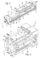
- the linear drive 1 has an elongated housing 2 with one inside, preferably a cylindrical contour Recording space 3 delimiting housing tube 9 on the front an end cover 4 is fastened on both sides.
- the Figures 5 and 6 show one of these housing covers 4 alone.
- the respective end cover 4 With its an end face - subsequently as a tube end face 19 designated - to one of the two axially oriented End faces 20 of the housing tube 9 attached so that the Receiving space 3 is closed fluid-tight on the end face.
- sealing means 21 are provided directly between the facing end faces 19, 20 can be placed, but in the exemplary embodiment are arranged on an insert part 22 which between the end cover 4 and the housing tube 9 is held and immersed a little into the recording space 3.
- the insert part 22 may be part of a general reference number 25 designated fluidic end position damping device, which with a drive part arranged in the interior of the receiving space 3 6 works together when this is in an end position moves.
- the drive part 6 is designed and divided as a piston the receiving space 3 in two axially successive working chambers. Via connection openings 7 on the two end covers 4 are provided and in each of the work rooms can lead to the supply and discharge of pressure medium regarding the work rooms. In this way can drive part 6 for a drive movement in cause the longitudinal direction 5 indicated by dash-dotted lines.
- the drive movement of the drive part 6 can be outside tap the housing 2 on a guide carriage 8, the via a driver 12 with the drive part 6 in the longitudinal direction of the housing 5 is motion-coupled.
- the guide carriage 8 is on a linear guide fixed to the housing 13 guided in the longitudinal direction 5 of the housing.
- the linear guide 13 is aligned parallel to the housing 2 and sits in the area of the outer circumference of the housing tube 9, with which it is firmly connected.
- the linear guide 13 and the housing tube 9 thus together form a structural unit, the following because the casing tube 9 is involved is referred to as tube unit 18.
- the linear guide 13 is in the embodiment of one Guide rail formed. It can be a separate component be by suitable fasteners on the outer circumference of the housing tube 9 is fixed, for example by screws or screwless by rolling.
- the embodiment shows a design in which the linear guide 13, in particular by extrusion, in one piece with the housing tube 9 is formed.
- the tube unit 18 is thus a one-piece component.
- the guide carriage 8 preferably has a U-like cross section and overlaps the linear guide 13 like a rider. there he cooperates with his two on the linear guide 13 sled legs flanking opposite long sides 11 each with one on the associated long side of the Linear guide 13 provided strip-like guide section 23.
- the guide sections 23 extend over the entire length of the linear guide 13.
- the carriage legs 11 can be used to interact with the guide sections 23 with schematically indicated rolling or sliding devices 17 be equipped.
- the guide carriage 8 is excluded from the linear guide 13 in the longitudinal direction of the housing 5 - supported on all sides. On has its top facing away from the linear guide 13 it is provided on a wing 15 on the fastening means 16 are so that a load to be transported is fixed can be.
- the longitudinal slot 26 preferably extends over the entire length of the housing tube 9. It runs in one Dash-dotted slot plane 32, which in the embodiment with respect to one of the two guide sections 23 of the linear guide 13 spanned guide level 24 runs inclined, in particular under one in FIG 2 identified acute angle 33.
- the outer The slot opening of the longitudinal slot 26 is the guide plane 24 facing.
- the top extends through the longitudinal slot 26 mentioned driver 12. This is on the one hand, on its inner End, with the drive part 6 and the other, with his outer end, with the guide carriage 8 so motion-coupled, that the components mentioned are always only common form moving unit movable in the longitudinal direction of the housing. Driving forces exerted fluidically on the drive part 6 are thus on the driver 12 on the carriage 8 transfer free of play. In this way, the Guide carriage 8 for a linear movement in two each other drive opposite directions of motion 46a, 46b that are rectified with the longitudinal direction 5 of the housing.
- the longitudinal slot 26 is one assigned band-like, flexible sealing device 38. It is able to axially slit the longitudinal slot 26 on both sides of the Seal driver 12 to the environment, so that the desired Fluid exposure is possible. In the area of the driver 12, the sealing device 38 from the longitudinal slot 26 lifted inwards and / or outwards so that the penetration of the Permit driver 12.
- the sealing device 38 contains in particular one for the Sealing of the receiving space 3 responsible inner sealing tape, that in the area of the inner slot opening with the Slit flanks of the longitudinal slot can work together. additional can be provided an outer masking tape in the Ingress of contaminants in the area of the outer slot opening prevented in the longitudinal slot 26.
- shock absorbers are formed by buffer elements 27, which in particular Are designed and held fixed to the housing.
- the buffer elements 27 have a plate-like flat shape and are aligned so that their plane of expansion is rectangular extends to the longitudinal direction 5 of the housing. You are in Transition area between the tube unit 18 and one each the end cover 4 placed.
- Each buffer element 27 contains a holding section 34 and an adjoining this buffer section 35.
- the Holding section 34 is used to fix the buffer element fixed to the housing 27 and intervenes between the Pipe unit 18 and the respective end cover attached on the end face 4 a.
- the buffer section 35 stands laterally over the pipe unit 18 and protrudes into the adjustment path of the guide carriage 8 into it.
- On the carriage 8 has the buffer section facing the front a resilient planar shock absorption section 42, which is slightly raised and the guide carriage 8 facing shock receiving surface 43, which in particular in a direction perpendicular to the longitudinal direction of the housing Level runs.
- the guide slide 8 If, during operation of the linear drive 1, the guide slide 8 reaches its end position, it bounces with it in the direction of movement leading sled face 47 on the Shock receiving surface 43 of the buffer section 35. by virtue of the resilience of the shock absorption part 42 can Shock receiving surface 43 slightly towards the end cover 4 retreat with the guide carriage on short Distance is braked.
- the impact force of the Guide carriage 8 counteracting counterforce provides predominantly the back of the buffer section 35 End cover 4, which is firmly connected to the tube unit 18 is.
- This fixed connection can be found in the Figure 3 indicated way by one or more screw connections 48 can be realized. It is in particular about detachable connections.
- the buffer element 27 consists of rubber-elastic material.
- the buffer element 27 is in one piece Body that is made up of an overall rubber elastic Material possessing properties, in particular one Elastomeric material.
- Such security measures are in the embodiment available. They contain two on the back of the buffer element 27 juxtaposed securing projections 52, each in a complementary securing recess open to the tube unit 18 53 engage in the longitudinal direction 5 of the housing.
- the securing projections 52 are in particular pin-like formed, the securing recesses 53 a have a bore-like shape.
- Each locking tab 52 expediently engages in a separate securing recess 53 a.
- the securing projections 52 are located and securing recesses 53 each with part of their Cross section within and with another part of their Cross section outside the outline of the tube unit 18.
- the buffer element 27 is preferably in a receiving recess 55 placed in the pipe-side end face 19 of the relevant end cover 4 is formed.
- This Receiving recess 55 has one of the facing End face 20 of the tube unit 18 covered inner recess portion 56 and a radially outward towards it subsequent outer recess portion 57, the outside of the outline of the tube unit 18 and thus not Assembled buffer element 27 seen to the guide carriage 8th is open.
- the buffer element 27 dips with its Holding portion 34 in the inner recess portion 56, while the buffer section 35 in the region of the outer recess section 57 comes to rest.
- Receiving recess 55 expediently open radially on the outside.
- the assembly and disassembly of the buffer element 27 is done by this measure also facilitated because it is at his can easily grasp outer edge 58.
- the securing recesses 53 are located within the Receiving recess 55.
- the buffer element 27 has expediently a following the edge course of the receiving recess 55 complementary contour.
- the buffer element 27 is expediently installed with the end cover not yet mounted on the pipe unit 18 4. It is in this state in the reception well 55 inserted, the locking projections 52 in the in the wall of the receiving recess 55 formed security recesses 53 intervene. It can be provided be that the locking protrusions 52 are lightly press-fit be fixed in the securing recesses 53.
- the buffer element 27 will be designed that the guide carriage 8 under standard conditions never on the pipe-side end face 19 of the end cover 4 crashes, but beforehand through the recess in the receptacle 55 protruding shock absorption section 42 caught and is braked.
Landscapes
- Engineering & Computer Science (AREA)
- Physics & Mathematics (AREA)
- Fluid Mechanics (AREA)
- Mechanical Engineering (AREA)
- General Engineering & Computer Science (AREA)
- Actuator (AREA)
- Bearings For Parts Moving Linearly (AREA)
- Transmission Devices (AREA)
- Vehicle Body Suspensions (AREA)
- Surgical Instruments (AREA)
- Materials For Medical Uses (AREA)
Abstract
Description
- Figur 1
- eine bevorzugte erste Bauform des erfindungsgemäßen kolbenstangenlosen Linearantriebes in perspektivischer Darstellung,
- Figur 2
- eine vergrößerte Teildarstellung des Linearantriebes aus Figur 1, wobei die aus Gehäuserohr und Linearführung bestehende Rohreinheit durchschnitten ist und wobei der Führungsschlitten strichpunktiert angedeutet ist, während das Antriebsteil, der Mitnehmer und die bandartige Dichtungseinrichtung nicht gezeigt sind,
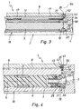
- Figur 3
- einen Längsschnitt durch den Linearantrieb aus Figuren 1 und 2 gemäß Schnittlinie III-III in Teildarstellung,
- Figur 4
- wiederum in Teildarstellung einen Längsschnitt durch den Linearantrieb der Figuren 1 und 2 gemäß Schnittlinie IV-IV,
- Figur 5
- eine Einzeldarstellung eines mit dem Pufferelement bestückten Abschlussdeckels des Gehäuses und
- Figur 6
- den Abschlussdeckel gemäß Figur 5 bei entferntem Pufferelement.
Claims (19)
- Kolbenstangenloser Linearantrieb, mit einem länglichen Gehäuse (2), das ein Gehäuserohr (9) und stirnseitig daran befestigte Abschlussdeckel (4) aufweist und in dem sich ein Aufnahmeraum (3) für ein in der Gehäuse-Längsrichtung (5) bewegliches Antriebsteil (6) befindet, das über einen einen Längsschlitz (26) des Gehäuserohres (9) durchsetzenden Mitnehmer (12) mit einem Führungsschlitten (8) bewegungsgekoppelt ist, der an einer mit dem Gehäuserohr (9) zu einer Rohreinheit (18) zusammengefassten Linearführung (13) in der Gehäuse-Längsrichtung (5) verstellbar geführt ist, wobei an mindestens einem Endbereich des Gehäuses (2) in den Verstellweg des Führungsschlittens (8) ragende Stoßaufnahmemittel vorgesehen sind, dadurch gekennzeichnet, dass die Stoßaufnahmemittel von einem Pufferelement (27) gebildet sind, das einen zur gehäusefesten Fixierung zwischen die Rohreinheit (18) und den zugeordneten Abschlussdeckel (4) eingreifenden Halteabschnitt (34) und einen seitlich über die Rohreinheit (18) vorstehenden Pufferabschnitt (35) aufweist, wobei der Pufferabschnitt (35) vorne eine dem Führungsschlitten (8) zugewandte, nachgiebige Stoßaufnahmepartie (42) besitzt und rückseitig von dem ebenfalls seitlich über die Rohreinheit (18) vorstehenden Abschlussdeckel (4) abgestützt ist.
- Linearantrieb nach Anspruch 1, dadurch gekennzeichnet, dass zumindest die Stoßaufnahmepartie (42) des Pufferelementes (27) aus gummielastischem Material besteht.
- Linearantrieb nach Anspruch 1 oder 2, dadurch gekennzeichnet, dass das Pufferelement (27) einstückig ausgebildet ist.
- Linearantrieb nach Anspruch 3, dadurch gekennzeichnet, dass das Pufferelement (27) aus gummielastischem Material besteht, vorzugsweise aus Elastomer-Material.
- Linearantrieb nach einem der Ansprüche 1 bis 4, dadurch gekennzeichnet, dass das Pufferelement (27) plattenartige Flachgestalt aufweist, wobei seine Ausdehnungsebene rechtwinkelig zur Gehäuse-Längsrichtung (5) verläuft.
- Linearantrieb nach einem der Ansprüche 1 bis 5, dadurch gekennzeichnet, dass das Pufferelement (27) in einer Aufnahmevertiefung (55) platziert ist, die in der der Rohreinheit (18) zugewandten rohrseitigen Stirnfläche (20) des zugeordneten Abschlussdeckels (4) ausgebildet ist und die einen von der Stirnfläche (20) der Rohreinheit (18) überdeckten inneren Vertiefungsabschnitt (56) aufweist, in den der Halteabschnitt (34) des Pufferelementes (27) eintaucht.
- Linearantrieb nach Anspruch 6, dadurch gekennzeichnet, dass der Pufferabschnitt (35) in einem außerhalb des Umrisses der Rohreinheit (18) liegenden äußeren Vertiefungsabschnitt (57) der Aufnahmevertiefung (55) angeordnet ist und ein Stück weit in Richtung zum Führungsschlitten (8) über den Abschlussdeckel (4) vorsteht.
- Linearantrieb nach Anspruch 7, dadurch gekennzeichnet, dass an dem Abschlussdeckel (4) neben dem äußeren Vertiefungsabschnitt (57) eine Anschlagfläche (62) für den Führungsschlitten (8) vorgesehen ist, die gegenüber der Stoßaufnahmefläche (43) des Pufferabschnittes (35) in der Gehäuse-Längsrichtung (5) zurückgesetzt ist.
- Linearantrieb nach einem der Ansprüche 6 bis 8, dadurch gekennzeichnet, dass die Aufnahmevertiefung (55) radial außen offen ist.
- Linearantrieb nach einem der Ansprüche 1 bis 9, dadurch gekennzeichnet, dass an dem Pufferelement (27) rückseitig mindestens ein Sicherungsvorsprung (52) angeordnet ist, der in eine zur Rohreinheit (18) hin offene Sicherungsausnehmung (53) des Abschlussdeckels (4) eingreift, sodass das Pufferelement (27) durch Formschluss quer zur Gehäuse-Längsrichtung (5) bezüglich des Gehäuses (2) lagegesichert ist.
- Linearantrieb nach Anspruch 10, gekennzeichnet durch zwei nebeneinander angeordnete und mit jeweils einer gesonderten Sicherungsausnehmung (53) in Eingriff stehende Sicherungsvorsprünge (52).
- Linearantrieb nach Anspruch 10 oder 11, dadurch gekennzeichnet, dass der mindestens eine Sicherungsvorsprung (52) zapfenartig und die zugeordnete Sicherungsausnehmung (53) bohrungsartig ausgebildet ist.
- Linearantrieb nach einem der Ansprüche 10 bis 12, dadurch gekennzeichnet, dass die Sicherungsvorsprünge (52) und Sicherungsausnehmungen (53) mit zumindest einem Teil ihres Querschnittes radial innerhalb des Umrisses der Rohreinheit (18) angeordnet sind.
- Linearantrieb nach einem der Ansprüche 10 bis 13, dadurch gekennzeichnet, dass die Sicherungsvorsprünge (52) und Sicherungsausnehmungen (53) mit einem Teil ihres Querschnittes innerhalb und mit dem anderen Teil ihres Querschnittes außerhalb des Umrisses der Rohreinheit (18) angeordnet sind.
- Linearantrieb nach einem der Ansprüche 1 bis 14, dadurch gekennzeichnet, dass der Halteabschnitt (34) des Pufferelementes (27) zwischen dem Abschlussdeckel (4) und der Linearführung (13) platziert ist.
- Linearantrieb nach einem der Ansprüche 1 bis 15, dadurch gekennzeichnet, dass die Linearführung (13) einstückig mit dem Gehäuserohr (9) ausgebildet ist.
- Linearantrieb nach einem der Ansprüche 1 bis 16, dadurch gekennzeichnet, dass beiden Endbereichen des Gehäuses (2) mindestens ein Pufferelement (27) zugeordnet ist.
- Linearantrieb nach einem der Ansprüche 1 bis 17, dadurch gekennzeichnet, dass die Linearführung (13) an ihren beiden einander entgegengesetzten Längsseiten über mit dem Führungsschlitten (8) kooperierende Führungsabschnitte (23) verfügt, die eine Führungsebene (24) aufspannen, bezüglich der die den Längsschlitz (26) enthaltende Schlitzebene (32) unter einem spitzen Winkel (33) schräg verläuft.
- Linearantrieb nach einem der Ansprüche 1 bis 18, gekennzeichnet durch eine durch Fluidkraft betätigbare Bauform, bei der das Antriebsteil (6) ein fluidisch beaufschlagbarer Kolben ist und bei der dem Längsschlitz (26) eine bandartige Dichtungseinrichtung (38) zugeordnet ist.
Applications Claiming Priority (2)
| Application Number | Priority Date | Filing Date | Title |
|---|---|---|---|
| DE20219272U | 2002-12-03 | ||
| DE20219272U DE20219272U1 (de) | 2002-12-03 | 2002-12-03 | Kolbenstangenloser Linearantrieb |
Publications (3)
| Publication Number | Publication Date |
|---|---|
| EP1426624A2 true EP1426624A2 (de) | 2004-06-09 |
| EP1426624A3 EP1426624A3 (de) | 2005-03-16 |
| EP1426624B1 EP1426624B1 (de) | 2008-02-13 |
Family
ID=7977911
Family Applications (1)
| Application Number | Title | Priority Date | Filing Date |
|---|---|---|---|
| EP03024743A Expired - Lifetime EP1426624B1 (de) | 2002-12-03 | 2003-10-29 | Kolbenstangenloser Linearantrieb |
Country Status (3)
| Country | Link |
|---|---|
| EP (1) | EP1426624B1 (de) |
| AT (1) | ATE386216T1 (de) |
| DE (2) | DE20219272U1 (de) |
Families Citing this family (1)
| Publication number | Priority date | Publication date | Assignee | Title |
|---|---|---|---|---|
| CN113898780B (zh) * | 2021-12-10 | 2022-03-11 | 中国空气动力研究与发展中心超高速空气动力研究所 | 一种与流量控制机构相配合的功能分离控制装置 |
Citations (2)
| Publication number | Priority date | Publication date | Assignee | Title |
|---|---|---|---|---|
| DE19531523C2 (de) | 1994-10-14 | 1997-08-14 | Festo Kg | Linearantrieb |
| EP1182359A1 (de) | 2000-08-23 | 2002-02-27 | FESTO AG & Co | Kolbenstangenloser Linearantrieb sowie zugehöriges Gehäuse |
Family Cites Families (3)
| Publication number | Priority date | Publication date | Assignee | Title |
|---|---|---|---|---|
| US6092456A (en) * | 1997-06-11 | 2000-07-25 | Howa Machinery, Ltd. | Rodless power cylinder |
| JP3543065B2 (ja) | 1999-04-16 | 2004-07-14 | Smc株式会社 | 直線作動装置 |
| JP4618578B2 (ja) | 2001-05-11 | 2011-01-26 | Smc株式会社 | リニアアクチュエータ |
-
2002
- 2002-12-03 DE DE20219272U patent/DE20219272U1/de not_active Expired - Lifetime
-
2003
- 2003-10-29 EP EP03024743A patent/EP1426624B1/de not_active Expired - Lifetime
- 2003-10-29 AT AT03024743T patent/ATE386216T1/de not_active IP Right Cessation
- 2003-10-29 DE DE50309150T patent/DE50309150D1/de not_active Expired - Lifetime
Patent Citations (2)
| Publication number | Priority date | Publication date | Assignee | Title |
|---|---|---|---|---|
| DE19531523C2 (de) | 1994-10-14 | 1997-08-14 | Festo Kg | Linearantrieb |
| EP1182359A1 (de) | 2000-08-23 | 2002-02-27 | FESTO AG & Co | Kolbenstangenloser Linearantrieb sowie zugehöriges Gehäuse |
Also Published As
| Publication number | Publication date |
|---|---|
| DE20219272U1 (de) | 2003-02-20 |
| EP1426624B1 (de) | 2008-02-13 |
| EP1426624A3 (de) | 2005-03-16 |
| DE50309150D1 (de) | 2008-03-27 |
| ATE386216T1 (de) | 2008-03-15 |
Similar Documents
| Publication | Publication Date | Title |
|---|---|---|
| EP1221559B1 (de) | Brems- und Dämpfeinrichtung, insbesondere für bewegbare Möbelteile | |
| DE2626236C3 (de) | Dichtungssitzringanordnung für einen Absperrschieber | |
| DE19715858C2 (de) | Kolben für einen Arbeitszylinder | |
| DE102007058628B4 (de) | Dämpferbefestigungsmechanismus | |
| DE102010022286A1 (de) | Luftdämpfungsmechanismus für einen Pneumatikzylinder | |
| EP2526825B1 (de) | Einzugvorrichtung | |
| DE112019002456B4 (de) | Zylindervorrichtung | |
| DE112008002320B4 (de) | Fluiddruckzylinder | |
| DE19931362C2 (de) | Dämpfungselement für Möbeltüren | |
| DE10258147B4 (de) | Kolbenstangenloser Linearantrieb | |
| CH666731A5 (de) | Kolben, insbesondere fuer hydraulische oder pneumatische arbeitszylinder. | |
| DE102013002425B3 (de) | Stoßdämpfer mit einer sich automatisch anpassenden Dämpfungscharakteristik | |
| DE2925642C2 (de) | ||
| EP1426624B1 (de) | Kolbenstangenloser Linearantrieb | |
| DE4039172C2 (de) | Arbeitszylinder mit Endlagendämpfung | |
| DE69916204T2 (de) | Stossdämpfer für einen Spielzeugbausatz | |
| EP1136346B1 (de) | Verbindungselement für eine elastische Verbindung zweier Bauteile | |
| AT15609U1 (de) | Dämpfungsvorrichtung | |
| DE202005016282U1 (de) | Ventilglied und damit ausgestattetes Ventil | |
| DE19934383A1 (de) | Dämpfungseinrichtung und Ventileinsatz für eine solche Dämpfungseinrichtung | |
| DE102019203466A1 (de) | Anschlagmodul | |
| DE202015004323U1 (de) | Vorrichtung zum Abdämpfen von Druckkräften | |
| DE19802775C2 (de) | Vorrichtung zur gedämpften Abbremsung zweier relativ zueinander bewegter Körper | |
| EP1426625B1 (de) | Kolbenstangenloser Linearantrieb | |
| DE102012004713B4 (de) | Kolben eines Linearantriebes und damit ausgestatteter Linearantrieb |
Legal Events
| Date | Code | Title | Description |
|---|---|---|---|
| PUAI | Public reference made under article 153(3) epc to a published international application that has entered the european phase |
Free format text: ORIGINAL CODE: 0009012 |
|
| AK | Designated contracting states |
Kind code of ref document: A2 Designated state(s): AT BE BG CH CY CZ DE DK EE ES FI FR GB GR HU IE IT LI LU MC NL PT RO SE SI SK TR |
|
| AX | Request for extension of the european patent |
Extension state: AL LT LV MK |
|
| PUAL | Search report despatched |
Free format text: ORIGINAL CODE: 0009013 |
|
| AK | Designated contracting states |
Kind code of ref document: A3 Designated state(s): AT BE BG CH CY CZ DE DK EE ES FI FR GB GR HU IE IT LI LU MC NL PT RO SE SI SK TR |
|
| AX | Request for extension of the european patent |
Extension state: AL LT LV MK |
|
| 17P | Request for examination filed |
Effective date: 20050324 |
|
| AKX | Designation fees paid |
Designated state(s): AT DE FR GB IT |
|
| GRAP | Despatch of communication of intention to grant a patent |
Free format text: ORIGINAL CODE: EPIDOSNIGR1 |
|
| GRAS | Grant fee paid |
Free format text: ORIGINAL CODE: EPIDOSNIGR3 |
|
| GRAA | (expected) grant |
Free format text: ORIGINAL CODE: 0009210 |
|
| AK | Designated contracting states |
Kind code of ref document: B1 Designated state(s): AT DE FR GB IT |
|
| REG | Reference to a national code |
Ref country code: GB Ref legal event code: FG4D Free format text: NOT ENGLISH |
|
| REF | Corresponds to: |
Ref document number: 50309150 Country of ref document: DE Date of ref document: 20080327 Kind code of ref document: P |
|
| GBT | Gb: translation of ep patent filed (gb section 77(6)(a)/1977) |
Effective date: 20080420 |
|
| ET | Fr: translation filed | ||
| PLBE | No opposition filed within time limit |
Free format text: ORIGINAL CODE: 0009261 |
|
| STAA | Information on the status of an ep patent application or granted ep patent |
Free format text: STATUS: NO OPPOSITION FILED WITHIN TIME LIMIT |
|
| 26N | No opposition filed |
Effective date: 20081114 |
|
| PGFP | Annual fee paid to national office [announced via postgrant information from national office to epo] |
Ref country code: AT Payment date: 20081027 Year of fee payment: 6 |
|
| PG25 | Lapsed in a contracting state [announced via postgrant information from national office to epo] |
Ref country code: AT Free format text: LAPSE BECAUSE OF NON-PAYMENT OF DUE FEES Effective date: 20091029 |
|
| PGFP | Annual fee paid to national office [announced via postgrant information from national office to epo] |
Ref country code: GB Payment date: 20130816 Year of fee payment: 11 |
|
| PGFP | Annual fee paid to national office [announced via postgrant information from national office to epo] |
Ref country code: FR Payment date: 20131018 Year of fee payment: 11 |
|
| PGFP | Annual fee paid to national office [announced via postgrant information from national office to epo] |
Ref country code: IT Payment date: 20131008 Year of fee payment: 11 |
|
| GBPC | Gb: european patent ceased through non-payment of renewal fee |
Effective date: 20141029 |
|
| PG25 | Lapsed in a contracting state [announced via postgrant information from national office to epo] |
Ref country code: GB Free format text: LAPSE BECAUSE OF NON-PAYMENT OF DUE FEES Effective date: 20141029 |
|
| REG | Reference to a national code |
Ref country code: FR Ref legal event code: ST Effective date: 20150630 |
|
| PG25 | Lapsed in a contracting state [announced via postgrant information from national office to epo] |
Ref country code: FR Free format text: LAPSE BECAUSE OF NON-PAYMENT OF DUE FEES Effective date: 20141031 Ref country code: IT Free format text: LAPSE BECAUSE OF NON-PAYMENT OF DUE FEES Effective date: 20141029 |
|
| PGFP | Annual fee paid to national office [announced via postgrant information from national office to epo] |
Ref country code: DE Payment date: 20150929 Year of fee payment: 13 |
|
| REG | Reference to a national code |
Ref country code: DE Ref legal event code: R119 Ref document number: 50309150 Country of ref document: DE |
|
| PG25 | Lapsed in a contracting state [announced via postgrant information from national office to epo] |
Ref country code: DE Free format text: LAPSE BECAUSE OF NON-PAYMENT OF DUE FEES Effective date: 20170503 |