EP1426594A2 - Steuervorrichtung und Steuerverfahren - Google Patents
Steuervorrichtung und Steuerverfahren Download PDFInfo
- Publication number
- EP1426594A2 EP1426594A2 EP20030027801 EP03027801A EP1426594A2 EP 1426594 A2 EP1426594 A2 EP 1426594A2 EP 20030027801 EP20030027801 EP 20030027801 EP 03027801 A EP03027801 A EP 03027801A EP 1426594 A2 EP1426594 A2 EP 1426594A2
- Authority
- EP
- European Patent Office
- Prior art keywords
- value
- correction value
- air
- fuel ratio
- parameter
- Prior art date
- Legal status (The legal status is an assumption and is not a legal conclusion. Google has not performed a legal analysis and makes no representation as to the accuracy of the status listed.)
- Granted
Links
Images


Classifications
-
- F—MECHANICAL ENGINEERING; LIGHTING; HEATING; WEAPONS; BLASTING
- F02—COMBUSTION ENGINES; HOT-GAS OR COMBUSTION-PRODUCT ENGINE PLANTS
- F02D—CONTROLLING COMBUSTION ENGINES
- F02D41/00—Electrical control of supply of combustible mixture or its constituents
- F02D41/02—Circuit arrangements for generating control signals
- F02D41/14—Introducing closed-loop corrections
- F02D41/1401—Introducing closed-loop corrections characterised by the control or regulation method
- F02D41/1402—Adaptive control
-
- F—MECHANICAL ENGINEERING; LIGHTING; HEATING; WEAPONS; BLASTING
- F02—COMBUSTION ENGINES; HOT-GAS OR COMBUSTION-PRODUCT ENGINE PLANTS
- F02D—CONTROLLING COMBUSTION ENGINES
- F02D41/00—Electrical control of supply of combustible mixture or its constituents
- F02D41/02—Circuit arrangements for generating control signals
- F02D41/14—Introducing closed-loop corrections
- F02D41/1438—Introducing closed-loop corrections using means for determining characteristics of the combustion gases; Sensors therefor
- F02D41/1444—Introducing closed-loop corrections using means for determining characteristics of the combustion gases; Sensors therefor characterised by the characteristics of the combustion gases
- F02D41/1454—Introducing closed-loop corrections using means for determining characteristics of the combustion gases; Sensors therefor characterised by the characteristics of the combustion gases the characteristics being an oxygen content or concentration or the air-fuel ratio
- F02D41/1458—Introducing closed-loop corrections using means for determining characteristics of the combustion gases; Sensors therefor characterised by the characteristics of the combustion gases the characteristics being an oxygen content or concentration or the air-fuel ratio with determination means using an estimation
-
- F—MECHANICAL ENGINEERING; LIGHTING; HEATING; WEAPONS; BLASTING
- F02—COMBUSTION ENGINES; HOT-GAS OR COMBUSTION-PRODUCT ENGINE PLANTS
- F02D—CONTROLLING COMBUSTION ENGINES
- F02D41/00—Electrical control of supply of combustible mixture or its constituents
- F02D41/24—Electrical control of supply of combustible mixture or its constituents characterised by the use of digital means
- F02D41/2406—Electrical control of supply of combustible mixture or its constituents characterised by the use of digital means using essentially read only memories
- F02D41/2425—Particular ways of programming the data
- F02D41/2429—Methods of calibrating or learning
- F02D41/2451—Methods of calibrating or learning characterised by what is learned or calibrated
- F02D41/2454—Learning of the air-fuel ratio control
-
- F—MECHANICAL ENGINEERING; LIGHTING; HEATING; WEAPONS; BLASTING
- F02—COMBUSTION ENGINES; HOT-GAS OR COMBUSTION-PRODUCT ENGINE PLANTS
- F02D—CONTROLLING COMBUSTION ENGINES
- F02D41/00—Electrical control of supply of combustible mixture or its constituents
- F02D41/24—Electrical control of supply of combustible mixture or its constituents characterised by the use of digital means
- F02D41/2406—Electrical control of supply of combustible mixture or its constituents characterised by the use of digital means using essentially read only memories
- F02D41/2425—Particular ways of programming the data
- F02D41/2429—Methods of calibrating or learning
- F02D41/2477—Methods of calibrating or learning characterised by the method used for learning
-
- F—MECHANICAL ENGINEERING; LIGHTING; HEATING; WEAPONS; BLASTING
- F02—COMBUSTION ENGINES; HOT-GAS OR COMBUSTION-PRODUCT ENGINE PLANTS
- F02D—CONTROLLING COMBUSTION ENGINES
- F02D41/00—Electrical control of supply of combustible mixture or its constituents
- F02D41/02—Circuit arrangements for generating control signals
- F02D41/14—Introducing closed-loop corrections
- F02D41/1401—Introducing closed-loop corrections characterised by the control or regulation method
- F02D2041/1413—Controller structures or design
- F02D2041/1415—Controller structures or design using a state feedback or a state space representation
- F02D2041/1416—Observer
-
- F—MECHANICAL ENGINEERING; LIGHTING; HEATING; WEAPONS; BLASTING
- F02—COMBUSTION ENGINES; HOT-GAS OR COMBUSTION-PRODUCT ENGINE PLANTS
- F02D—CONTROLLING COMBUSTION ENGINES
- F02D41/00—Electrical control of supply of combustible mixture or its constituents
- F02D41/02—Circuit arrangements for generating control signals
- F02D41/14—Introducing closed-loop corrections
- F02D41/1401—Introducing closed-loop corrections characterised by the control or regulation method
- F02D2041/1413—Controller structures or design
- F02D2041/1418—Several control loops, either as alternatives or simultaneous
-
- F—MECHANICAL ENGINEERING; LIGHTING; HEATING; WEAPONS; BLASTING
- F02—COMBUSTION ENGINES; HOT-GAS OR COMBUSTION-PRODUCT ENGINE PLANTS
- F02D—CONTROLLING COMBUSTION ENGINES
- F02D41/00—Electrical control of supply of combustible mixture or its constituents
- F02D41/02—Circuit arrangements for generating control signals
- F02D41/14—Introducing closed-loop corrections
- F02D41/1401—Introducing closed-loop corrections characterised by the control or regulation method
- F02D2041/1413—Controller structures or design
- F02D2041/1423—Identification of model or controller parameters
-
- F—MECHANICAL ENGINEERING; LIGHTING; HEATING; WEAPONS; BLASTING
- F02—COMBUSTION ENGINES; HOT-GAS OR COMBUSTION-PRODUCT ENGINE PLANTS
- F02D—CONTROLLING COMBUSTION ENGINES
- F02D41/00—Electrical control of supply of combustible mixture or its constituents
- F02D41/02—Circuit arrangements for generating control signals
- F02D41/14—Introducing closed-loop corrections
- F02D41/1401—Introducing closed-loop corrections characterised by the control or regulation method
- F02D2041/1433—Introducing closed-loop corrections characterised by the control or regulation method using a model or simulation of the system
- F02D2041/1437—Simulation
-
- F—MECHANICAL ENGINEERING; LIGHTING; HEATING; WEAPONS; BLASTING
- F02—COMBUSTION ENGINES; HOT-GAS OR COMBUSTION-PRODUCT ENGINE PLANTS
- F02D—CONTROLLING COMBUSTION ENGINES
- F02D2200/00—Input parameters for engine control
- F02D2200/02—Input parameters for engine control the parameters being related to the engine
- F02D2200/04—Engine intake system parameters
- F02D2200/0402—Engine intake system parameters the parameter being determined by using a model of the engine intake or its components
-
- F—MECHANICAL ENGINEERING; LIGHTING; HEATING; WEAPONS; BLASTING
- F02—COMBUSTION ENGINES; HOT-GAS OR COMBUSTION-PRODUCT ENGINE PLANTS
- F02D—CONTROLLING COMBUSTION ENGINES
- F02D41/00—Electrical control of supply of combustible mixture or its constituents
- F02D41/008—Controlling each cylinder individually
-
- F—MECHANICAL ENGINEERING; LIGHTING; HEATING; WEAPONS; BLASTING
- F02—COMBUSTION ENGINES; HOT-GAS OR COMBUSTION-PRODUCT ENGINE PLANTS
- F02D—CONTROLLING COMBUSTION ENGINES
- F02D41/00—Electrical control of supply of combustible mixture or its constituents
- F02D41/02—Circuit arrangements for generating control signals
- F02D41/14—Introducing closed-loop corrections
- F02D41/1438—Introducing closed-loop corrections using means for determining characteristics of the combustion gases; Sensors therefor
- F02D41/1444—Introducing closed-loop corrections using means for determining characteristics of the combustion gases; Sensors therefor characterised by the characteristics of the combustion gases
- F02D41/1454—Introducing closed-loop corrections using means for determining characteristics of the combustion gases; Sensors therefor characterised by the characteristics of the combustion gases the characteristics being an oxygen content or concentration or the air-fuel ratio
- F02D41/1456—Introducing closed-loop corrections using means for determining characteristics of the combustion gases; Sensors therefor characterised by the characteristics of the combustion gases the characteristics being an oxygen content or concentration or the air-fuel ratio with sensor output signal being linear or quasi-linear with the concentration of oxygen
-
- F—MECHANICAL ENGINEERING; LIGHTING; HEATING; WEAPONS; BLASTING
- F02—COMBUSTION ENGINES; HOT-GAS OR COMBUSTION-PRODUCT ENGINE PLANTS
- F02D—CONTROLLING COMBUSTION ENGINES
- F02D41/00—Electrical control of supply of combustible mixture or its constituents
- F02D41/02—Circuit arrangements for generating control signals
- F02D41/18—Circuit arrangements for generating control signals by measuring intake air flow
- F02D41/182—Circuit arrangements for generating control signals by measuring intake air flow for the control of a fuel injection device
Definitions
- the present invention relates to a control system and method that control a plant, using a model defining the relationship between a simulation value simulating the behavior of an internal variable of the plant and a detection value reflecting the behavior of the internal variable.
- This air-fuel ratio control system is comprised of a LAF sensor disposed in the collecting section of an exhaust pipe, for detecting the air-fuel ratio of exhaust gases, a control unit to which a detection signal (indicative of the detected air-fuel ratio) from the LAF sensor is input, and injectors disposed in the intake manifold of the exhaust pipe for the respective cylinders and connected to the control unit.
- variation in air-fuel ratio of exhaust gases emitted from a plurality of cylinders i.e. variation in air-fuel ratio of the mixture between the cylinders is corrected by calculating a cylinder-by-cylinder fuel injection amount as the amount of fuel to be injected from each injector into the associated cylinder, based on the detected air-fuel ratio output from the LAF sensor, using the observer and by PID control, as described below.
- control unit calculates the basic fuel injection amount depending on the operating conditions of the engine, and multiplies the basic fuel injection amount by various correction coefficients to calculate the output fuel injection amount. Then, as described in detail hereinbelow, the observer calculates a cylinder-by-cylinder estimated air-fuel ratio, and a cylinder-by-cylinder estimated feedback correction coefficient is determined by PID control based on the estimated cylinder-by-cylinder air-fuel ratio. The cylinder-by-cylinder fuel injection amount is calculated by multiplying an output fuel injection amount by the cylinder-by-cylinder feedback correction coefficient.
- the cylinder-by-cylinder estimated air-fuel ratio is calculated by the observer based on the optimal control theory. More specifically, by using a model of a discrete-time system representative of the relationship between a cylinder-by-cylinder fuel-air ratio and a fuel-air ratio detected at the collecting section (where the LAF sensor is disposed), the cylinder-by-cylinder estimated air-fuel ratio is calculated. Further, in the PID control, a value obtained by dividing the fuel-air ratio detected at the collecting section, i.e.
- the detected air-fuel ratio, by the average value of the respective preceding values of the feedback correction coefficients is set to a target value, and the cylinder-by-cylinder feedback correction coefficient is calculated such that the difference between the target value and the cylinder-by-cylinder estimated air-fuel ratio calculated by the observer converges to a value of 0.
- Another air-fuel ratio control system which calculates the fuel injection amount on a cylinder-by-cylinder basis, based on an estimated intake air amount calculated by estimating the amount of intake air to be supplied to each of a plurality of cylinders, on a cylinder-by-cylinder basis, and an estimated air-fuel ratio calculated on a cylinder-by-cylinder basis by an observer similar to that described above (see e.g. Japanese Laid-Open Patent Publication (Kokai) No. 6-74076, pages, 3-12, FIGS. 1 and 31).
- this air-fuel ratio control system calculates a target intake fuel amount by searching a map according to the engine speed and the intake pipe pressure. Further, by applying a fluid dynamics model to the intake system of the engine, the estimated intake air amount is calculated on a cylinder-by-cylinder basis, and the estimated air-fuel ratio is calculated on a cylinder-by-cylinder basis, by the observer described above. Further, by dividing the estimated intake air amount by the estimated air-fuel ratio, an estimated intake fuel amount is calculated on a cylinder-by-cylinder basis, and a final fuel injection amount is calculated by an adaptive controller such that the estimated intake fuel amount becomes equal to the target intake fuel mount.
- the air-fuel ratio control system does not have a sufficient stability against changes in the contributions of exhaust gases from the individual cylinders to the detected air-fuel ratio of the LAF sensor caused by attachment of fuel, etc., changes in the response of the LAF sensor, and the aging of the same.
- the second-described air-fuel ratio control system which uses the observer similar to that used in the first-described air-fuel ratio control system, there can be a case in which the observer cannot establish itself for the reason described above. In such a case, the fuel injection amount cannot be properly calculated on a cylinder-by-cylinder basis, which can degrade the emission reduction rate of the catalyst.
- variation also occurs in intake air amount between the cylinders.
- the second-described air-fuel ratio control system does not consider the correction of the variation in intake air amount, and only estimates the intake air amount on a cylinder-by-cylinder basis, by applying the fluid dynamics model thereto. Therefore, the variation in intake air amount between the cylinders cannot be properly corrected, which brings about variation in the air-fuel ratio between the cylinders, causing further degradation of emission reduction rate of the catalyst.
- a control system for controlling a plant comprising:
- the detection value reflecting the behavior of the first internal variable of the plant is detected, and the estimation value of the detection value is estimated based on a model defining the relationship between the estimation value and the simulation value simulating the behavior of the first internal variable.
- the model parameter of the model is identified according to the detection value and the simulation value, such that the estimated estimation value becomes equal to the detected detection value, and the first input to be inputted to the plant is determined according to the identified model parameter.
- the model parameter is identified such that the estimated estimation value becomes equal to the detected detection value, which enables the model parameter to be identified as a value in which the actual behavior of the first internal variable is properly reflected, particularly, enables the model parameter to be identified as a value in which the actual behavior of the first internal variable is reflected in real time, when an onboard identifier is used as the identification means.
- the first input is determined according to the thus identified model parameter, so that even when the first internal variable is drastically changed, the first input can be determined as a value in which the behavior of the first internal variable is promptly and properly reflected, and by using the first input thus determined, it is possible to promptly and properly control the first internal variable to a predetermined state or a predetermined value.
- the plant when the plant is to be controlled such that the first input causes the detection value detected by the detection means to converge to a predetermined target value, even if the S/N ratio or sensitivity of the detection means is low, it is possible to set the detection value susceptible to the behavior of the first internal variable to the predetermined target value promptly with stability by causing the behavior of the first internal variable to be reflected in the first input. That is, it is possible to realize a control having a higher robustness and a larger margin of stability than the prior art.
- control system further comprises second control means for determining a second input to be inputted to the plant such that the detection value is caused to converge to a predetermined target value, the first internal variable comprising a plurality of first internal variables, the simulation value comprising a plurality of simulation values simulating respective behaviors of the plurality of first internal variables, the model parameter comprising a plurality of model parameters, and the identification means identifies the plurality of model parameters according to the detection value and the plurality of simulation values such that the estimated estimation value becomes equal to the detected detection value, the first control means determining the first input such that the identified model parameters converge to an average value thereof.
- the second control means determines the second input to be inputted to the plant such that the detection value is caused to converge to the predetermined target value, and the identification means identifies the plurality of model parameters according to the detection value and the plurality of simulation values such that the estimated estimation value becomes equal to the detected detection value.
- the first control means determines the first input such that the identified model parameters converge to the average value thereof.
- the first input is determined such that the identified values of the plurality of model parameters converge to the average value thereof, which makes it possible to prevent a control process for causing the detection value detected by the detection means to converge to the predetermined target value and a control process for controlling the first internal variable from interfering with each other, and at the same time correct variation in behavior between the plurality of first internal variables.
- the first control means comprises learned correction value-calculating means for calculating a learned correction value of the first input, using a sequential statistical algorithm, correction means for correcting the first input using the calculated learned correction value, and input means for inputting the corrected first input to the plant.
- the least-squares method is generally employed as the identifying computational algorithm.
- the identifying computation by the least-squares method after collecting a plurality of numbers of various data for computation, the computation is executed collectively based on the collected data. Therefore, at the start of the control, the identification of the model parameter is not executed until completion of collection of the data, which makes it impossible to calculate the first input based on the identified value of the model parameter, which can degrade the controllability.
- the learned correction value of the first input is calculated with the sequential statistical algorithm, which enables the first input to be corrected even at the start of the control by the learned correction value calculated every control cycle. Therefore, e.g. by setting an initial value of the first input in advance, even before the model parameter is newly identified at the start of the control, the first input can be always corrected by the learned correction value calculated every control cycle, whereby the controllability at the start of the control can be enhanced.
- the learned correction value-calculating means calculates the learned correction value of the first input using a regression equation in which the learned correction value is used as a dependent variable and a second internal variable having influence on the first internal variable is used as an independent variable, and calculates a regression coefficient and a constant term of the regression equation with the sequential statistical algorithm.
- the learned correction value of the first input is calculated using the regression equation in which the learned correction value is used as the dependent variable and a second internal variable having influence on the first internal variable is used as the independent variable, and the regression coefficient and the constant term of the regression equation are calculated with the sequential statistical algorithm. Therefore, even when the rate of change in the second internal variable is very high, making the rate of change in the first internal variable also so high that it is difficult to estimate the first internal variable, it is possible to calculate the learned correction value as a value in which the actual state of the first internal variable is properly reflected, thereby further enhancing the controllability of the first internal variable by the first input.
- the first control means determines an input component contained in the first input based on a difference between the model parameter and a predetermined target value.
- the plant can be controlled such that model parameter converges to a predetermined target value, thereby causing the first internal variable of the plant to converge to a predetermined value without causing a steady-state deviation.
- the first control means determines other input components than the input component contained in the first input, based on the model parameter.
- the first input contains not only the input component determined based on the difference between the model parameter and the predetermined target value, but also the other input components determined based on the model parameter. Therefore, e.g. when the plant is controlled such that the model parameter converges to the predetermined target value, the first internal variable of the plant can be controlled that it converges to the predetermined value without causing overshooting or an oscillatory behavior. As a result, the detection value can be controlled to the stable state while preventing the same from becoming oscillatory or being overshot.
- the first control means determines the first input according to the model parameter with a response-specified control algorithm.
- the first input is determined according to the model parameter with the response-specified control algorithm, and therefore, it is possible to control the plant, for example, such that model parameter converges to the predetermined target value, whereby the first internal variable of the plant can be controlled such that it converges to the predetermined value without causing overshooting or an oscillatory behavior.
- the detection value can be controlled to a stable state while preventing the same from becoming oscillatory or overshot.
- the identification means identifies the model parameter by a fixed gain method.
- the model parameter is identified by the fixed gain method, and therefore, it is possible to reduce computational load on the identification means. This makes it possible to shorten the computing time of the first input, whereby it is possible to calculate the first input promptly and properly as a value in which the behavior of the first internal variable is properly reflected, even when the rate of change in the first internal variable is high.
- the identified value of the model parameter can be constrained to values close to the reference value, which makes it possible to prevent an increase in the rate of change in the first internal variable from causing the state of the first internal variable to be unsuitably reflected in the identified value of the model parameter, thereby making it possible to enhance the stability of the control.
- the identification means identifies the model parameter by calculating a model parameter reference value according to the second internal variable, and adding a predetermined correction component to the calculated model parameter reference value.
- the model parameter is identified by adding the predetermined correction component to the model parameter reference value calculated according to the second internal variable. This makes it possible to constrain the identified value of the model parameter to values close to the model parameter reference value, whereby even when the rate of change in the first internal variable is high due to the influence of change in the second internal variable, it is possible to promptly and properly calculate the first input as a value in which the behavior of the first internal variable is properly reflected, thereby enhancing the stability of the control.
- control system further comprises delay means for delaying one of the detection value and the simulation value by a predetermined delay time period, and the identification means identifies the model parameter according to the delayed one of the detection value and the simulation value, and the other of the detection value and the simulation value.
- the model parameter is identified according to the delayed one of the detection value and the simulation value, and the other of the detection value and the simulation value. Therefore, e.g. when the detection value or the simulation value surfers from the dead time, it is possible to identify the model parameter with accuracy while taking the dead time into account, thereby further enhancing the stability of the control.
- control system further comprises filter means for generating a filtered value of the detection value by subjecting the detection value to predetermined filtering processing, and the identification means identifies the model parameter according to the filtered value of the detection value and the simulation value.
- the identification means identifies the model parameter according to the filtered value of the detection value obtained by subjecting the detection value to the predetermined filtering processing and the simulation value, and therefore, by properly setting the filtering characteristics of the filtering processing, it is possible, even when the absolute value of the detection value changes over a wide range, the filtered value of the detection value can be generated as a value which positively contains information necessary for identification of the model parameter, i.e.
- a control system for an internal combustion engine including a plurality of cylinders, a plurality of exhaust passages extending from the plurality of cylinders, respectively, and one exhaust passage into which the plurality of exhaust passages are combined, the control system controlling an amount of fuel to be supplied to the plurality of cylinders, on a cylinder-by-cylinder basis, thereby controlling an air-fuel ratio of exhaust gases emitted from the plurality of cylinders, the control system comprising:
- the amount of fuel to be supplied to each of the plurality of cylinders is determined by the fuel amount-determining means, and the air-fuel ratio parameter indicative of the air-fuel ratio of exhaust gases in the one exhaust passage is detected by the air-fuel ratio parameter-detecting means.
- the estimation value of the air-fuel ratio parameter is estimated based on the model defining the relationship between the estimation value and the plurality of simulation values simulating respective behaviors of air-fuel ratios of exhaust gases emitted from the plurality of cylinders, and the plurality of model parameters of the model are identified by the identification means such that the estimation value of the air-fuel ratio parameter becomes equal to the detected air-fuel ratio parameter.
- the first correction value for correcting the amount of fuel to be supplied to the plurality of cylinders is calculated according to the identified plurality of model parameters, on a cylinder-by-cylinder basis, by the first correction value-calculating means.
- the determined fuel amount is corrected according to the calculated first correction value, on a cylinder-by-cylinder basis, by the first fuel amount-correcting means.
- the plurality of model parameters are identified such that the estimation value of the air-fuel ratio parameter becomes equal to the detected air-fuel ratio parameter, which makes it possible to identify the plurality of model parameters as values in which the actual behaviors of exhaust gases emitted from the plurality of cylinders, i.e. variation in air-fuel ratio between the cylinders is reflected therein.
- control system further comprises second correction value-calculating means for calculating a second correction value for correcting the amount of fuel to be supplied to each cylinder, such that the air-fuel ratio parameter is caused to converge to a predetermined target value, and second fuel amount-correcting means for correcting the amount of fuel to be supplied to each cylinder according to the calculated second correction value, and the first correction value-calculating means calculates the first correction value, on a cylinder-by-cylinder basis, such that the identified plurality of model parameters converge to an average value thereof.
- the second correction value-calculating means calculates the second correction value for correcting the amount of fuel to be supplied to each cylinder, such that the air-fuel ratio parameter is caused to converge to the predetermined target value, and the second fuel amount-correcting means corrects the amount of fuel to be supplied to each cylinder according to the calculated second correction value.
- the first correction value-calculating means calculates the first correction value, on a cylinder-by-cylinder basis, such that the identified plurality of model parameters converge to an average value thereof.
- the first correction value is calculated such that the identified plurality of model parameters converge to an average value thereof, and therefore it is possible to correct variation in air-fuel ratio between the cylinders, whereby it is possible to prevent the control process for causing the air-fuel ratio parameter to converge to a predetermined target value and the control process for correcting variation in air-fuel ratio between the cylinders from interfering with each other, thereby ensuring stability of the air-fuel ratio control.
- control system further comprises learned correction value-calculating means for calculating a learned correction value of the first correction value with a sequential statistical algorithm, on a cylinder-by-cylinder basis, and the first fuel amount-correcting means corrects the amount of fuel further according to the calculated learned correction value, on a cylinder-by-cylinder basis.
- the least-squares method is generally employed as the identifying computational algorithm
- the computation is executed collectively based on the collected data. Therefore, at the start of the air-fuel ratio control, the identification of the model parameter is not executed until completion of collection of the data. This makes it impossible to calculate the first correction value based on the identified value of the model parameter, which can degrade the controllability of the air-fuel ratio control.
- the learned correction value of the first correction value is calculated with the sequential statistical algorithm, which enables the first correction value to be corrected by the learned correction value calculated every control cycle even at the start of the air-fuel ratio control.
- control system further comprises operating condition parameter-detecting means for detecting an operating condition parameter indicative of an operating condition of the engine, and the learned correction value-calculating means calculates the learned correction value using a regression equation in which the learned correction value is used as a dependent variable and the detected operating condition parameter is used as an independent variable, and calculates a regression coefficient and a constant term of the regression equation with the sequential statistical algorithm.
- the learned correction value of the first correction value is calculated using a regression equation in which the learned correction value of the first correction value is used as a dependent variable and the detected operating condition parameter is used as an independent variable, and the regression coefficient and the constant term of the regression equation are calculated with the sequential statistical algorithm. Therefore, even when the engine is in a drastically changing operating condition, such as a transient operating condition, causing a sudden change of the air-fuel ratio, which makes it difficult to estimate the air-fuel ratio, it is possible to calculate the learned correction value as a value in which the actual state of the air-fuel ratio of each cylinder is properly reflected, thereby further enhancing the controllability of the air-fuel ratio control.
- the first correction value-calculating means calculates a correction value component contained in the first correction value based on a difference between the identified model parameters and a predetermined target value.
- the first correction value-calculating means calculates the correction value component contained in the first correction value based on the difference between the identified model parameters and the predetermined target value. Therefore, the amount of fuel can be corrected such that model parameters converge to the predetermined target value, thereby providing control on the air-fuel ratio, on a cylinder-by-cylinder basis, such that the air-fuel ratio converges to a predetermined value without causing a steady-state deviation.
- the first correction value-calculating means calculates other correction value components than the correction value component contained in the first correction value, based on the identified model parameters.
- the first correction value contains not only the correction value component determined based on the difference between the model parameters and the predetermined target value, but also the other correction value components determined based on the model parameters. Therefore, e.g. when the amount of fuel is controlled, on a cylinder-by-cylinder basis, such that the model parameters converge to the predetermined target value, the air-fuel ratio can be controlled, on a cylinder-by-cylinder basis, such that it converges to the predetermined value without causing overshooting or an oscillatory behavior, with stability.
- the first correction value-calculating means calculates the first correction value according to the model parameters with a response-specified control algorithm.
- the first correction value is determined according to the model parameters with the response-specified control algorithm, and therefore, it is possible to correct the amount of fuel, for example, such that model parameters converge to the predetermined target value, whereby the air-fuel ratio can be corrected, on a cylinder-by-cylinder basis, such that it converges to the predetermined value without causing overshooting or an oscillatory behavior, with stability.
- the identification means identifies the model parameters by a fixed gain method.
- the model parameters are identified by the fixed gain method, and therefore, it is possible to reduce computational load on the identification means. This makes it possible to shorten the computing time of the first correction value, whereby it is possible to calculate the first correction value promptly and properly, on a cylinder-by-cylinder basis, as a value in which the behavior of the air-fuel ratio is properly reflected, even when the rate of change in the air-fuel ratio of each cylinder is high due to a transient operating condition of the engine.
- the identified values of the model parameters can be constrained to values close to the reference values, which makes it possible to prevent an increase in the rate of change in the air-fuel ratio from causing the actual state of the air-fuel ratio to be unsuitably reflected in the identified values of the model parameters, thereby making it possible to further enhance the stability of the air-fuel ratio control.
- the identification means identifies the model parameters by calculating respective model parameter reference values according to the operating condition parameter, and adding predetermined correction components to the calculated model parameter reference values, respectively.
- the model parameters are identified by adding the respective predetermined correction components to the model parameter reference values calculated according to the operating condition parameter. This makes it possible to constrain the identified values of the model parameters to respective values close to the model parameter reference values, whereby even when the rate of change in the air-fuel ratio is high due to the influence of change in the operating condition of the engine, it is possible to promptly and properly calculate the first correction value, on a cylinder-by-cylinder basis, as a value in which the behavior of the air-fuel ratio is properly reflected, thereby further enhancing the stability of the control.
- control system further comprises delay means for delaying the air-fuel ratio parameter by a predetermined delay time period, and the identification means identifies the model parameters according to the delayed air-fuel ratio parameter and the plurality of simulation values.
- the model parameter is identified according to the delayed air-fuel ratio parameter, which is delayed by the predetermined dead time, and the plurality of model parameters. Therefore, it is possible to identify the model parameter with accuracy while taking the dead time into account, thereby further enhancing the stability of the control.
- a control system for an internal combustion engine including one intake passage, a plurality of intake passages branching from the one intake passage, and a plurality of cylinders connected to the plurality of intake passages extend, respectively, the control system controlling an amount of fuel to be supplied to the plurality of cylinders, on a cylinder-by-cylinder basis, thereby controlling an air-fuel ratio of exhaust gases emitted from the plurality of cylinders, the control system comprising:
- the fuel amount-determining means determines the amount of fuel to be supplied to each cylinder, and the intake air amount parameter-detecting means disposed in the one intake passage detects the intake air amount parameter indicative of the amount of intake air.
- the estimation means estimates the estimation value of the intake air amount parameter based on the model defining the relationship between the estimation value and the plurality of simulation values simulating respective behaviors of amounts of intake air to be drawn into the plurality of cylinders, and the identification means identifies the plurality of model parameters of the model such that the estimation value of the intake air amount parameter becomes equal to the detected intake air amount parameter.
- the third correction value-calculating means calculates the third correction value for correcting the amount of fuel to be supplied to the plurality of cylinders, according to the identified plurality of model parameters, on a cylinder-by-cylinder basis, and the third fuel amount-correcting means corrects the determined fuel amount according to the calculated third correction value, on a cylinder-by-cylinder basis.
- the plurality of model parameters are identified such that the estimation value of the intake air amount parameter becomes equal to the detected intake air amount parameter, which makes it possible to identify the plurality of model parameters as values in which the actual behaviors of amounts of intake air drawn into the cylinders are reflected therein, i.e. variation in intake air amount between the cylinders is reflected therein.
- the engine includes a plurality of exhaust passages extending from the plurality of cylinders, respectively, and one exhaust passage into which the plurality of exhaust passages are combined
- the control system further comprises intake air amount parameter-detecting means for detecting an intake air amount parameter indicative of an air-fuel ratio of exhaust gases in the one exhaust passage, fourth correction value-calculating means for calculating a fourth correction value for correcting the amount of fuel to be supplied to each cylinder, such that the detected air-fuel ratio parameter is caused to converge to a predetermined target value, and fourth fuel amount-correcting means for correcting the amount of fuel to be supplied to each cylinder according to the calculated fourth correction value, the third correction value-calculating means calculating the third correction value, on a cylinder-by-cylinder basis, such that the identified plurality of model parameters converge to an average value thereof.
- the fourth correction value-calculating means calculates the fourth correction value for correcting the amount of fuel to be supplied to each cylinder, such that the air-fuel ratio parameter is caused to converge to the predetermined target value, and the fourth fuel amount-correcting means corrects the amount of fuel to be supplied to each cylinder according to the calculated fourth correction value. Further, the third correction value-calculating means calculates the third correction value, on a cylinder-by-cylinder basis, such that the identified plurality of model parameters converge to an average value thereof.
- the third correction value is calculated such that the identified plurality of model parameters converge to an average value thereof, which makes it possible to correct variation in intake air amount between the cylinders, whereby it is possible to prevent the control process for causing the air-fuel ratio parameter to converge to the predetermined target value and the control process for correcting variation in intake air amount between the cylinders from interfering with each other, thereby ensuring stability of the air-fuel ratio control.
- control system further comprises learned correction value-calculating means for calculating a learned correction value of the third correction value with a sequential statistical algorithm, on a cylinder-by-cylinder basis, and the third fuel amount-correcting means corrects the amount of fuel further according to the calculated learned correction value, on a cylinder-by-cylinder basis.
- the identification of the model parameter is not executed until completion of collection of the data at the start of the control, which makes it impossible to calculate the third correction value based on the identified value of the model parameter, which can degrade the controllability of the air-fuel ratio control.
- the learned correction value of the third correction value is calculated with the sequential statistical algorithm, which enables the third correction value to be corrected by the learned correction value calculated every control cycle even at the start of the control.
- control system further comprises operating condition parameter-detecting means for detecting an operating condition parameter indicative of an operating condition of the engine, and the learned correction value-calculating means calculates the learned correction value using a regression equation in which the learned correction value is used as a dependent variable and the detected operating condition parameter is used as an independent variable, and calculates a regression coefficient and a constant term of the regression equation with the sequential statistical algorithm.
- the learned correction value of the third correction value is calculated using the regression equation in which the learned correction value is used as the dependent variable and the detected operating condition parameter is used as the independent variable, and the regression coefficient and the constant term of the regression equation are calculated with the sequential statistical algorithm. Therefore, even when the engine is in a drastically changing operating condition, such as a transient operating condition, causing a sudden change of the air-fuel ratio, which makes it difficult to estimate the first internal variable, it is possible to calculate the learned correction value as a value in which the actual state of the amount of intake air supplied to each cylinder is properly reflected, thereby further enhancing the controllability of the air-fuel ratio control.
- the third correction value-calculating means calculates a correction value component contained in the third correction value based on a difference between the identified model parameters and a predetermined target value.
- the third correction value-calculating means calculates the correction value component contained in the third correction value based on the difference between the identified model parameters and the predetermined target value. Therefore, the amount of fuel can be corrected such that the model parameters converge to a predetermined target value, thereby providing control on the intake air amount on a cylinder-by-cylinder basis such that the intake air amount converges to a predetermined value without causing a steady-state deviation.
- the third correction value-calculating means calculates other correction value components than the correction value component contained in the third correction value, based on the identified model parameters.
- the third correction value contains not only the correction value component determined based on the difference between the model parameters and the predetermined target value, but also other correction value components determined based on the model parameters. Therefore, e.g. when the amount of fuel is controlled on a cylinder-by-cylinder basis such that the model parameters converge to the predetermined target value, the amount of intake air can be controlled, on a cylinder-by-cylinder basis, such that it converges to the predetermined value without causing overshooting or an oscillatory behavior, with stability.
- the third correction value-calculating means calculates the third correction value according to the model parameters with a response-specified control algorithm.
- the third correction value is determined according to the model parameters with the response-specified control algorithm, and therefore, it is possible to correct the amount of fuel, for example, such that model parameters converge to the predetermined target value, whereby the amount of intake air can be corrected, on a cylinder-by-cylinder basis, such that it converges to the predetermined value without causing overshooting or an oscillatory behavior, with stability.
- the identification means identifies the model parameters by a fixed gain method.
- the model parameters are identified by the fixed gain method, and therefore, it is possible to reduce computational load on the identification means. This makes it possible to shorten the computing time of the third correction value, whereby it is possible to calculate the third correction value promptly and properly, on a cylinder-by-cylinder basis, as a value in which the behavior of the amount of intake air is properly reflected, even when the rate of change in the amount of intake air of each cylinder is high due to a transient operating condition of the engine.
- the identified values of the model parameters can be constrained to values close to the reference values, which makes it possible to prevent an increase in the rate of change in the intake air amount from causing the actual state of the intake air amount to be unsuitably reflected in the identified values of the model parameters, thereby making it possible to further enhance the stability of the air-fuel ratio control.
- the identification means identifies the model parameters by calculating respective model parameter reference values according to the operating condition parameter, and adding predetermined correction components to the calculated model parameter reference values, respectively.
- the model parameters are identified by adding the respective predetermined correction components to the model parameter reference values calculated according to the operating condition parameter. This makes it possible to constrain the identified values of the model parameters to values close to the model parameter reference values, whereby even when the rate of change in the amount of intake air is high due to the influence of change in the operating condition of the engine, it is possible to promptly and properly calculate the third correction value, on a cylinder-by-cylinder basis, as a value in which the behavior of the amount of intake air is properly reflected, thereby further enhancing the stability of the control.
- control system further comprises delay means for delaying the plurality of simulation values by a predetermined delay time period, and the identification means identifies the model parameters according to the intake air amount parameter and the delayed plurality of simulation values.
- the model parameters are identified according to the intake air amount parameter and the plurality of delayed simulation values, which is delayed by the predetermined dead time. Therefore, it is possible to identify the model parameters with accuracy while taking the dead time into account, thereby further enhancing the stability of the control.
- control system further comprises filter means for generating a filtered value of the intake air amount parameter by subjecting the intake air amount parameter to predetermined filtering processing, and the identification means identifies the model parameters according to the generated filtered value of the intake air amount parameter and the plurality of simulation values.
- the identifying process by the identification means can be incapable of following up the change, which can cause delay in identification of the model parameters, causing degraded accuracy of the identification.
- the identification means identifies the model parameters according to the filtered value of the intake air amount parameter obtained by subjecting the intake air amount parameter to predetermined filtering processing and the simulation values, and therefore, by properly setting the filtering characteristics of the filtering processing, it is possible, even when the absolute value of the intake air amount parameter changes over a wide range, the filtered value of the intake air amount parameter value can be generated as a value which positively contains information necessary for identification of the model parameter, i.e. information indicative of the behavior (variation and the like) of the intake air of each cylinder, and is suppressed in the range of change thereof. Therefore, by identifying using the filtered value and the simulation values, it is possible to suppress delay in the identification of the model parameters and enhance the accuracy of the identification, thereby further enhancing the stability and response of the air-fuel ratio control.
- a control method for controlling a plant comprising:
- control method further comprises a second control step of determining a second input to be inputted to the plant such that the detection value is caused to converge to a predetermined target value, the first internal variable comprising a plurality of first internal variables, the simulation value comprising a plurality of simulation values simulating respective behaviors of the plurality of first internal variables, the model parameter comprising a plurality of model parameters, and the identification step includes identifying the plurality of model parameters according to the detection value and the plurality of simulation values such that the estimated estimation value becomes equal to the detected detection value, the first control step including determining the first input such that the identified model parameters converge to an average value thereof.
- the first control step comprises a learned correction value-calculating step of calculating a learned correction value of the first input, using a sequential statistical algorithm, a correction step of correcting the first input using the calculated learned correction value, and an input step of inputting the corrected first input to the plant.
- the learned correction value-calculating step includes calculating the learned correction value of the first input using a regression equation in which the learned correction value is used as a dependent variable and a second internal variable having influence on the first internal variable is used as an independent.variable, and calculating a regression coefficient and a constant term of the regression equation with the sequential statistical algorithm.
- the first control step includes determining an input component contained in the first input based on a difference between the model parameter and a predetermined target value.
- the first control step includes determining other input components than the input component contained in the first input, based on the model parameter.
- the first control step includes determining the first input according to the model parameter with a response-specified control algorithm.
- the identification step includes identifying the model parameter by a fixed gain method.
- the identification step includes identifying the model parameter by calculating a model parameter reference value according to the second internal variable, and adding a predetermined correction component to the calculated model parameter reference value.
- control method further comprises a delay step of delaying one of the detection value and the simulation value by a predetermined delay time period, and the identification step includes identifying the model parameter according to the delayed one of the detection value and the simulation value, and the other of the detection value and the simulation value.
- control method further comprises a filter step of generating a filtered value of the detection value by subjecting the detection value to predetermined filtering processing, and the identification step includes identifying the model parameter according to the filtered value of the detection value and the simulation value.
- a control method for an internal combustion engine including a plurality of cylinders, a plurality of exhaust passages extending from the plurality of cylinders, respectively, and one exhaust passage into which the plurality of exhaust passages are combined, the control method controlling an amount of fuel to be supplied to the plurality of cylinders, on a cylinder-by-cylinder basis, thereby controlling an air-fuel ratio of exhaust gases emitted from the plurality of cylinders, the control method comprising:
- control method further comprises a second correction value-calculating step of calculating a second correction value for correcting the amount of fuel to be supplied to each cylinder, such that the air-fuel ratio parameter is caused to converge to a predetermined target value, and a second fuel amount-correcting step of correcting the amount of fuel to be supplied to each cylinder according to the calculated second correction value, and the first correction value-calculating step includes calculating the first correction value, on a cylinder-by-cylinder basis, such that the identified plurality of model parameters converge to an average value thereof.
- control method further comprises a learned correction value-calculating step of calculating a learned correction value of the first correction value with a sequential statistical algorithm, on a cylinder-by-cylinder basis, and the first fuel amount-correcting step includes correcting the amount of fuel further according to the calculated learned correction value, on a cylinder-by-cylinder basis.
- control method further comprises an operating condition parameter-detecting step of detecting an operating condition parameter indicative of an operating condition of the engine, and the learned correction value-calculating step includes calculating the learned correction value using a regression equation in which the learned correction value is used as a dependent variable and the detected operating condition parameter is used as an independent variable, and calculating a regression coefficient and a constant term of the regression equation with the sequential statistical algorithm.
- the first correction value-calculating step includes calculating a correction value component contained in the first correction value based on a difference between the identified model parameters and a predetermined target value.
- the first correction value-calculating step includes calculating other correction value components than the correction value component contained in the first correction value, based on the identified model parameters.
- the first correction value-calculating step includes calculating the first correction value according to the model parameters with a response-specified control algorithm.
- the identification step includes identifying the model parameters by a fixed gain method.
- the identification step includes identifying the model parameters by calculating respective model parameter reference values according to the operating condition parameter, and adding predetermined correction components to the calculated model parameter reference values, respectively.
- control method further comprises a delay step of delaying the air-fuel ratio parameter by a predetermined delay time period, and the identification step includes identifying the model parameters according to the delayed air-fuel ratio parameter and the plurality of simulation values.
- a control method for an internal combustion engine including one intake passage, a plurality of intake passages branching from the one intake passage, and a plurality of cylinders connected to the plurality of intake passages extend, respectively, the control method controlling an amount of fuel to be supplied to the plurality of cylinders, on a cylinder-by-cylinder basis, thereby controlling an air-fuel ratio of exhaust gases emitted from the plurality of cylinders, the control method comprising:
- the engine includes a plurality of exhaust passages extending from the plurality of cylinders, respectively, and one exhaust passage into which the plurality of exhaust passages are combined
- the control method further comprises an air-fuel ratio parameter-detecting step of detecting an air-fuel ratio parameter indicative of an air-fuel ratio of exhaust gases in the one exhaust passage, a fourth correction value-calculating step of calculating a fourth correction value for correcting the amount of fuel to be supplied to each cylinder, such that the detected air-fuel ratio parameter is caused to converge to a predetermined target value, and a fourth fuel amount-correcting step of correcting the amount of fuel to be supplied to each cylinder according to the calculated fourth correction value, the third correction value-calculating step including calculating the third correction value, on a cylinder-by-cylinder basis, such that the identified plurality of model parameters converge to an average value thereof.
- control method further comprises a learned correction value-calculating step of calculating a learned correction value of the third correction value with a sequential statistical algorithm, on a cylinder-by-cylinder basis, and the third fuel amount-correcting step includes correcting the amount of fuel further according to the calculated learned correction value, on a cylinder-by-cylinder basis.
- control method further comprises an operating condition parameter-detecting step of detecting an operating condition parameter indicative of an operating condition of the engine, and the learned correction value-calculating step includes calculating the learned correction value using a regression equation in which the learned correction value is used as a dependent variable and the detected operating condition parameter is used as an independent variable, and calculating a regression coefficient and a constant term of the regression equation with the sequential statistical algorithm.
- the third correction value-calculating step includes calculating a correction value component contained in the third correction value based on a difference between the identified model parameters and a predetermined target value.
- the third correction value-calculating step includes calculating other correction value components than the correction value component contained in the third correction value, based on the identified model parameters.
- the third correction value-calculating step includes calculating the third correction value according to the model parameters with a response-specified control algorithm.
- the identification step includes identifying the model parameters by a fixed gain method.
- the identification step includes identifying the model parameters by calculating respective model parameter reference values according to the operating condition parameter, and adding predetermined correction components to the calculated model parameter reference values, respectively.
- control method further comprises a delay step of delaying the plurality of simulation values by a predetermined delay time period, and the identification step includes identifying the model parameters according to the intake air amount parameter and the delayed plurality of simulation values.
- control method further comprises a filter step of generating a filtered value of the intake air amount parameter by subjecting the intake air amount parameter to predetermined filtering processing, and the identification step includes identifying the model parameters according to the generated filtered value of the intake air amount parameter and the plurality of simulation values.
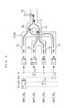
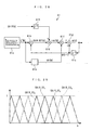
- FIG. 1 there is schematically shown the arrangement of an control system 1 according to a first embodiment of the present invention and an internal combustion engine 3, as a plant, to which the control system 1 is applied.
- the control system 1 includes an ECU 2 which controls the amount of fuel injected into the internal combustion engine (hereinafter simply referred to as "the engine") 3 according to operating conditions of the engine 3, to thereby control the air-fuel ratio of the mixture, as described in detail hereinafter.
- the engine 3 is an inline four-cylinder gasoline engine installed on an automotive vehicle, not shown, and has first to fourth cylinders #1 to #4 (a plurality of cylinders).
- the engine 3 has an intake pipe 4 which includes a main pipe 4a (one intake air passage), and an intake manifold 4b connected thereto.
- a throttle valve 5 is arranged across an intermediate portion of the main pipe 4a.
- the air flow sensor 9 detects the amount of intake air GAIR (detection value, intake air amount parameter) drawn into the engine via the intake pipe 4, and delivers a signal indicative of the detected amount of intake air to the ECU 2.
- GAIR detection value, intake air amount parameter
- the intake pipe absolute pressure sensor 11 is implemented e.g. by a semiconductor pressure sensor, which detects the intake pipe absolute pressure PBA (detection value, intake air amount parameter) of the intake pipe 4, and delivers a signal indicative of the detected intake pipe absolute pressure PBA to the ECU 2.
- the air flow sensor 9 forms the detection means, the operating condition parameter-detecting means, and the intake air amount parameter-detecting means, while the intake pipe absolute pressure sensor 11 forms the detection means and the intake air amount parameter-detecting means.
- a throttle valve opening sensor 10 implemented e.g. by a potentiometer, for detecting the degree of opening (hereinafter referred to as "throttle valve opening") TH of the throttle valve 5 and delivering an electric signal indicative of the sensed throttle valve opening TH to the ECU 2.
- the intake manifold 4b of the intake pipe 4 is comprised of a collecting section 4c (one intake passage) connected to the main pipe 4a, and four branch portions 4d (plurality of intake passages) branching from the collecting section 4c and connected to the four cylinders #1 to #4, respectively.
- injectors 6 are inserted at respective locations upstream of intake ports, not shown, for the cylinders.
- each injector 6 is controlled in respect of a fuel injection amount, i.e. a time period over which the injector 6 is open, and fuel injection timing, by a drive signal delivered from the ECU 2.
- an engine coolant temperature sensor 12 implemented e.g. by a thermistor is mounted in the cylinder block of the engine 3.
- the engine coolant temperature sensor 12 senses an engine coolant temperature TW which is the temperature of an engine coolant circulating through the cylinder block of the engine 3 and delivering a signal indicative of the sensed engine coolant temperature TW to the ECU 2.
- a crank angle position sensor 13 (operating condition parameter-detecting means) is provided for a crankshaft, not shown, of the engine 3, for delivering a CRK signal and a TDC signal, which are both pulse signals, to the ECU 2 in accordance with rotation of the crankshaft.
- Each pulse of the CRK signal is generated whenever the crankshaft rotates through a predetermined angle (e.g. 30 degrees).
- the ECU 2 determines a rotational speed (hereinafter referred to as "the engine speed") NE of the engine 3, based on the CRK signal.
- the TDC signal indicates that each piston, not shown, in an associated cylinder is in a predetermined crank angle position immediately before the TDC position at the start of the intake stroke, and each pulse of the TDC signal is generated whenever the crankshaft rotates through a predetermined angle.
- the exhaust pipe 7 includes an exhaust manifold 7b connected to the four cylinders #1 to #4, and an main pipe 7a connected to a collecting section 7j of the exhaust manifold 7b.
- the exhaust manifold 7b is configured such that four exhaust pipe sections 7c to 7f (a plurality of exhaust passages) extending from the four cylinders #1 to #4 are combined into two collecting sections, and the two collecting sections are combined into one collecting section.
- the exhaust manifold 7b is comprised of two exhaust pipe sections 7c and 7f extending from the respective first and fourth cylinders #1 and #4, a collecting section 7g into which these exhaust pipe sections 7c and 7f are combined, two exhaust pipe sections 7d and 7e extending from the respective second and third cylinders #2 and #3, and a collecting section 7h into which these exhaust pipe sections 7d and 7e are combined, and a collecting section 7j (one exhaust passage) into which the two collecting sections 7g and 7h are combined, all of these components being integrally formed in one piece. Due to such a configuration, the exhaust manifold 7b has a lower resistance to the flow of exhaust gases than a conventional exhaust manifold in which four exhaust pipe sections are directly combined into one collecting section. This enables the engine 3 to deliver higher power output and higher torque, compared with those having the conventional exhaust manifold.
- a first catalytic device 8a and a second catalytic devices 8b are arranged in the exhaust pipe 7 from upstream to downstream in the mentioned order in a spaced relationship at respective locations of the main pipe 7a of the intake pipe 7.
- Each catalytic device 8 is a combination of a NOx catalyst and a three-way catalyst, and the NOx catalyst is comprised of a honeycomb structure base, an iridium catalyst (sintered body of silicon carbide whiskers carrying iridium and silica) coated on the surface of the honeycomb structure base, and Perovskite double oxide (sintered body of LaCoO 3 powder and silica) further coated on the iridium catalyst.
- the catalytic device 8 eliminates NOx from exhaust gases emitted during a lean burn operation of the engine 3 by oxidation-reduction reaction-catalyzing action of the NOx catalyst, and eliminates CO, HC, and NOx from exhaust gases emitted during other operations of the engine 3 than the lean burn operation by oxidation-reduction reaction-catalyzing action of the three-way catalyst.
- the 02 sensor 15 is inserted into the main pipe 7a between the first and second catalytic devices 8a and 8b.
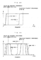
- the 02 sensor 15 is comprised of a zirconia layer and platinum electrodes, and delivers to the ECU 2 an output Vout dependent on the concentration of oxygen contained in exhaust gases downstream of the first catalytic device 8a.
- the output Vout assumes a high-level voltage value (e.g. 0.8 V) when an air-fuel mixture having a richer air-fuel ratio than the stoichiometric air-fuel ratio has been burned, whereas it assumes a low-level voltage value (e.g.
- the output Vout assumes a predetermined target value Vop (e.g. 0.6 V) between the high-level and low-level voltage values.
- a LAF sensor 14 is mounted in the vicinity of the collecting section 7d of the exhaust manifold 7a.
- the LAF sensor 14 (detection means, air-fuel ratio parameter-detecting means) is formed by combining a sensor similar to the 02 sensor 15 and a detection circuit, such as a linearizer, and detects the concentration of oxygen contained in exhaust gases linearly over a wide range of the air-fuel ratio ranging from a rich region to a lean region, thereby delivering an output proportional to the sensed oxygen concentration to the ECU 2.
- the ECU 2 calculates a detected air-fuel ratio KACT (detection value, air-fuel ratio parameter) indicative of the air-fuel ratio of exhaust gases at the collecting section 7j based on the output from the LAF sensor 14.
- the detected air-fuel ratio KACT is expressed as an equivalent ratio proportional to the reciprocal of the air-fuel ratio.
- the ECU 2 has an accelerator pedal opening sensor 16, an atmospheric pressure sensor 17, an intake air temperature sensor 18, and a vehicle speed sensor 19, connected thereto.
- the accelerator pedal opening sensor 16 detects a depression amount (hereinafter referred to as "the accelerator pedal opening") AP of an accelerator pedal, not shown, of the vehicle and delivers a signal indicative of the sensed accelerator pedal opening AP to the ECU 12.
- the atmospheric pressure sensor 17, the intake air temperature sensor 18, and the vehicle speed sensor 19 detect atmospheric pressure AP, intake air temperature TA, and vehicle speed VP, respectively, and delivers respective signals indicative of the detected atmospheric pressure AP, intake air temperature TA, and vehicle speed VP to the ECU 2.
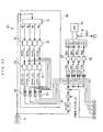
- the ECU 2 is implemented by a microcomputer including an input/output interface, a CPU, a RAM, and a ROM, none of which is shown.
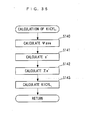
- the ECU 2 determines operating conditions of the engine 3, based on the outputs from the aforementioned sensors 9 to 19. Further, the ECU 2 executes an air-fuel ratio control process, which will be described in detail hereinafter, according to control programs read from the ROM, using data stored in the RAM, and the like, to thereby calculate a target air-fuel ratio KCMD, a feedback correction coefficient KSTR, an air-fuel ratio variation correction coefficient KOBSV i , and a learned correction value KOBSV_LS i thereof.
- the ECU 2 calculates a final fuel injection amount TOUT i for each injector 6, on a cylinder-by-cylinder basis, and drives the injector 6 by a drive signal generated based on the calculated final fuel injection amount TOUT i , to thereby control the air-fuel ratio of the mixture, i.e. air-fuel ratio of exhaust gases, on a cylinder-by-cylinder basis.
- the ECU 2 forms simulation value-generating means, estimation means, identification means, first control means, second control means, learned correction value-calculating means, correction means, input means, delay means, fuel amount-determining means, first correction value-calculating means, first fuel amount-correcting means, second correction value-calculating means, second fuel amount-correcting means, operating condition parameter-detecting means, third correction value-calculating means, third fuel amount-correcting means, fourth correction value-calculating means, and fourth fuel amount-correcting means.
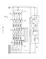
- the control system 1 is comprised of a basic fuel injection amount-calculating section 20, a first air-fuel ratio controller 30, a second air-fuel ratio controller 40, and a fuel attachment-dependent correcting section 50, which are all implemented by the ECU 2.
- the basic fuel injection amount-calculating section 20 as the fuel amount-determining means, calculates a basic fuel injection amount TIBS according to the intake air amount GAIR by searching a table, not shown.
- the first air-fuel ratio controller 30 calculates the air-fuel ratio variation correction coefficient KOBSV i and the learned correction value KOBSV_LS i thereof, and the second air-fuel ratio controller 40 calculates the feedback correction coefficient KSTR so as to cause the detected air-fuel ratio KACT to converge to the target air-fuel ratio KCMD.
- a demanded fuel injection amount TCYL i is calculated on a cylinder-by-cylinder basis by multiplying the basic fuel injection amount TIBS by a corrected target air-fuel ratio KCMDM, a total correction coefficient KTOTAL, the feedback correction coefficient KSTR, the air-fuel ratio variation correction coefficient KOBSV i , and the learned correction value KOBSV_LS i thereof. Then, the fuel attachment-dependent correcting section 50 calculates the final fuel injection amount TOUT i based on the demanded fuel injection amount TCYL i , on a cylinder-by-cylinder basis.
- the first air-fuel ratio controller 30 (first fuel amount-correcting means )is for correcting variation in air-fuel ratio between the cylinders, and is comprised of an adaptive observer 31, an air-fuel ratio variation correction coefficient-calculating section 32, a learned correction value-calculating section 33, and a multiplication section 34.
- the adaptive observer 31 calculates an air-fuel ratio variation coefficient ⁇ i , on a cylinder-by-cylinder basis
- the air-fuel ratio variation correction coefficient-calculating section 32 calculates the air-fuel ratio variation correction coefficient KOBSV i , on a cylinder-by-cylinder basis
- the learned correction value-calculating section 33 calculates the learned correction value KOBSV_LS i of the air-fuel ratio variation correction coefficient, on a cylinder-by-cylinder basis.
- the multiplication section 34 multiplies the air-fuel ratio variation correction coefficient KOBSV 1 to KOBSV 4 by the learned correction value KOBSV_LS 1 to KOBSV_LS 4 , respectively. That is, the air-fuel ratio variation correction coefficient KOBSV i is corrected by the learned correction value KOBSV_LS i .
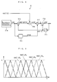
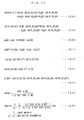
- the intake system of the engine 3 is regarded as a system which is represented by four simulation values KACT_OS 1 to KACT_OS 4 and four air-fuel ratio variation coefficients ⁇ 1 to ⁇ 4 .
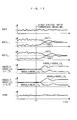
- These simulation values KACT_OS i are values simulating the exhaust timing and exhaust behavior of exhaust gases, on a cylinder-by-cylinder basis, and the air-fuel ratio variation coefficient ⁇ i represents variation in air-fuel ratio of exhaust gases between the cylinder and the amount of change in the exhaust behavior.
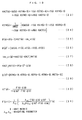
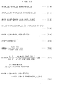
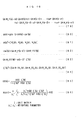
- the symbol k represents a discretized time, and indicates that each discrete data (time-series data) with (k) is data sampled whenever a pulse of the TDC signal is generated. This also applies to discrete data referred to hereinafter. (Each discrete data may be data sampled whenever a pulse of the CRK signal is generated.) Further, the symbol d represents dead time (predetermined delay time) which the exhaust gases emitted from each cylinder take to reach the LAF sensor LAF, and is set to a predetermined fixed value in the present embodiment in advance. The dead time d may be set depending on an operating condition (engine speed NE) of the engine 3.
- the adaptive observer 31 uses an equation formed by replacing the left side of the equation (1) by the estimation value KACT_EST of the air-fuel ratio, i.e. an equation (2) in FIG. 4 as a model, and a signal generator 31a generates the simulation value KACT_OS i .
- the vector ⁇ (k) of the air-fuel ratio variation coefficient ⁇ i as a model parameter of the equation (2) is identified by a variable-gain sequential least-squares method expressed by equations (3) to (9) in FIG. 4 such that the estimation value KACT_EST(k) becomes equal to the detected air-fuel ratio KACT(k).
- the symbol KP(k) in the equation (3) represents a vector of a gain coefficient
- the symbol ide(k) represents an identification error
- ⁇ (k) T in the equation (4) represents a transposed matrix of ⁇ (k). It should be noted in the following description, the notation of "vector” is omitted unless otherwise required.
- the identification error ide(k) in the equation (3) is calculated using the equations (5) to (7) in FIG. 4, and the symbol ⁇ (k) in the equation (6) represents a vector of the simulation values defined by the equation (7).
- the vector KP(k) of the gain coefficient is calculated by an equation (8) in FIG. 4, and the symbol P(k) in this equation (8) represents a square matrix of order 4 defined by an equation (9) in FIG. 4.
- This adaptive observer 31 identifies the vector ⁇ (k) of the air-fuel ratio variation coefficient ⁇ i with the algorithm based on the sequential least-squares method shown in the equations (2) to (9). This makes it possible to remove (filter off) noise-like fluctuating components of the exhaust behavior caused by a sudden change in the operating condition of the engine 3 from the air-fuel ratio variation coefficient ⁇ i , and thereby calculate the air-fuel ratio variation coefficient ⁇ i as a value substantially indicative of variation in air-fuel ratio between the cylinders.
- the configuration of the adaptive observer 31 can be represented by a block diagram shown in FIG. 5. That is, as shown in FIG. 5, in the adaptive observer 31, the signal generator 31a generates the vector ⁇ (k) of the simulation values KACT_OS i . More specifically, as shown in FIG. 6, the signal generator 31a generates the simulation values KACT_OS i as signal values each having a waveform of a combination of triangular waves and trapezoidal waves formed such that the total sum of the simulation values constantly becomes equal to a value of 1. Further, the multiplier 31b generates the estimation value KACT_EST(k) of the air-fuel ratio as a value obtained by multiplying the vector ⁇ (k) of the simulation values by the vector ⁇ (k-1) of the air-fuel ratio variation coefficient. Then, the differentiator 31d generate the identification error ide(k) as the difference between the detected air-fuel ratio KACT(k) and the estimation value KACT_EST(k).
- a logic unit 31e generates the vector KP(k) of the gain coefficient based on the vector ⁇ (k) of the simulation values, and a multiplier 31f generates the product [ide(k) ⁇ KP(k)] of the identification error ide(k) and the vector KP(k) of the gain coefficient.
- an adder 31g generates the vector ⁇ (k) of the air-fuel ratio variation coefficient as the sum of the product [ide(k) ⁇ KP(k)] and the delayed vector ⁇ (k-1) of the air-fuel ratio variation coefficient.
- the air-fuel ratio variation correction coefficient-calculating section 32 calculates the air-fuel ratio variation correction coefficient KOBSV i (first input, first correction value).
- the moving average value ⁇ ave(k) of the air-fuel ratio coefficient is calculated based on the air-fuel ratio variation coefficient ⁇ i (k) calculated by the adaptive observer 31, on a cylinder-by-cylinder basis, by an equation (10) in FIG. 7.
- the air-fuel ratio variation correction coefficient KOBSV i is calculated with I-PD control (proportional/differential-preceding PID control) algorithm, on a cylinder-by-cylinder basis, such that the air-fuel ratio variation coefficient ⁇ i (k) converges to the moving average value ⁇ ave(k) thereof.
- I-PD control proportional/differential-preceding PID control
- This I-PD control algorithm is expressed by equations (11) and (12) in FIG. 7.
- the symbol e(k) in the equation (12) represents a following error.
- the air-fuel ratio variation correction coefficient-calculating section 32 calculates the air-fuel ratio variation correction coefficient KOBSV i , with the I-PD control algorithm, such that the air-fuel ratio variation coefficient ⁇ i (k) converges to the moving average value ⁇ ave(k) thereof.
- This is for providing control such that the converging behavior of the air-fuel ratio variation coefficient ⁇ i (k) to the moving average value ⁇ ave(k) thereof does not suffer from overshooting, thereby preventing the air-fuel ratio control by the first air-fuel ratio controller 30 for correcting variation in air-fuel ratio between the cylinders and the air-fuel ratio control by the second air-fuel ratio controller 40, described hereinafter, from interfering with each other.
- FIG. 8A shows the relationship between an exhaust gas volume ESV(k) as an operating condition parameter indicative of an operating condition of the engine and the air-fuel ratio variation correction coefficient KOBSV i (k).
- This exhaust gas volume ESV(k) (second internal variable, operating condition parameter) is an estimation value of the space velocity, and calculated using an equation (13) in FIG. 9.
- the symbol SVPRA represents a predetermined coefficient determined in advance by the displacement of the engine 3.
- an approximate value i.e. estimation value of the air-fuel ratio variation correction coefficient KOBSV i (k) can be calculated by a first-degree equation using the air-fuel ratio variation correction coefficient KOBSV i (k) as a dependent variable and the exhaust gas volume ESV(k) as an independent variable (see FIG. 8B). Therefore, in the learned correction value-calculating section 33, the learned correction value KOBSV_LS i (k) of the air-fuel ratio variation correction coefficient is defined as an estimation value calculated by a regression equation, i.e. an equation (14) in FIG.
- a vector ⁇ OBSV_LS i (k) of a regression coefficient AOBSV_LS i and a constant term BOBSV_LS i (hereinafter referred to as "the regression coefficient vector") is calculated by a sequential least-squares method expressed by equations (15) to (21) in FIG. 9.
- the symbol KQ i (k) represents a vector of a gain coefficient
- the symbol Eov i (k) represents an error.
- the error Eov i (k) is calculated using equations (17) to (19) in FIG. 9.
- the vector KQ i (k) of the gain coefficient is calculated using an equation (20) in FIG. 9, and the symbol Q i (k) in this equation (20) represents a square matrix of order 2 defined by an equation (21) in FIG. 9.
- the learned correction value KOBSV_LS i (k) is more specifically calculated using an equation (22) in FIG. 9. It should be noted that when the engine 3 is in an extreme operating condition or operating environment, the calculation of the regression coefficient AOBSV_LS i and the constant term BOBSV_LS i by the sequential least-squares method is avoided, and the immediately preceding value ⁇ OBSV_LS i (k-1) of the regression coefficient vector is used as the current value ⁇ OBSV_LS i (k) in calculation of the learned correction value KOBSV_LS i (k).
- the learned correction value-calculating section 33 calculates the learned correction value KOBSV_LS i (k) such that the learned correction value KOBSV_LS i (k) converges to the product of the learned correction value KOBSV_LS i (k) and the air-fuel ratio variation correction coefficient KOBSV i (k).
- the second air-fuel ratio controller 40 is formed as an STR (Self Tuning Regulator) comprised of an onboard identifier 41 and an STR controller 42.
- the second air-fuel ratio controller 40 calculates the feedback correction coefficient KSTR such that the detected air-fuel ratio KACT converges to the target air-fuel ratio KCMD (predetermined target value). More specifically, with an algorithm described hereinbelow, the onboard identifier 41 identifies a model parameter vector ⁇ of the first cylinder #1, and the STR controller 42 calculates the feedback correction coefficient KSTR (second input, second and fourth correction values).
- this second air-fuel ratio controller 40 forms the second control means, the second correction value-calculating means, the second fuel amount-correcting means, the fourth correction value-calculating means, and the fourth fuel amount-correcting means.
- the first cylinder #1 is regarded as a controlled object to which is inputted the feedback correction coefficient KSTR and from which is outputted the detected air-fuel ratio KACT, and this controlled object is modeled into a discrete-time system model, which is expressed by an equation (23) in FIG. 10.
- the symbol n represents a discretized time, and indicates that each discrete data with (n) is sampled every combustion cycle, i.e. whenever a total of four successive pulses of the TDC signal are generated. This also applies to discrete data referred to hereinafter.
- the vector ⁇ (n) of model parameters b0(n), r1(n), r2(n), r3(n), and sO(n) in the equation (23) is identified with an identification algorithm expressed by equations (25) to (31) in FIG. 10.
- the symbol K ⁇ (n) in the equation (25) represents a vector of a gain coefficient
- the symbol ide_st(n) represents an identification error.
- the symbol ⁇ (n) T in the equation (26) represents a transposed matrix of ⁇ (n).
- the identification error ide_st(n) in the equation (25) is calculated using the equations (27) to (29) in FIG. 10, and the symbol KACT_HAT(n) in the equation (28) represents an identified value of the detected air-fuel ratio KACT. Further, the vector K ⁇ (n) of the gain coefficient is calculated using the equation (30) in FIG. 10, and the symbol ⁇ (n) in the equation (30) is a square matrix of order 5 defined by the equation (31) in FIG. 10.
- the second air-fuel ratio controller 40 calculates the feedback correction coefficient KSTR in the following manner:
- the model parameter vector ⁇ of the first cylinder #1 identified by the onboard identifier 41 is oversampled in timing synchronous with generation of the TDC signal, and at the same time, a moving average value ⁇ _ave of the model parameter vector ⁇ is calculated. More specifically, the moving average value ⁇ _ave(k) of the model parameter vector ⁇ is calculated using an equation (32) in FIG. 11, and the feedback correction coefficient KSTR(k) is calculated using the moving average value ⁇ _ave(k) by an equation (34) in FIG. 11.
- the symbol ⁇ buf in the equation (32) indicates an oversampling value of the model parameter vector ⁇ for the first cylinder #1, and the moving average value ⁇ _ave(k) is defined by an equation (33) in FIG. 11.
- the symbol m in the equation (32) represents a predetermined integer, and in the present embodiment, m is set to 11.
- the above equation (34) is derived.
- the identification algorithm with which the model parameter vector ⁇ (k) is identified is expressed by equations (35) to (41) shown in FIG. 11.
- the onboard identifier 40 identifies the model parameter vector ⁇ with the identification algorithm expressed by the equations (35) to (41) in FIG. 11, and the STR controller 42 calculates the feedback correction coefficient KSTR(k) using the equations (32) to (34) in FIG. 11.
- FIG. 12 shows a main routine for carrying out the control process, which is executed by an interrupt handling routine in synchronism with inputting of each pulse of the TDC signal.
- the final fuel injection amount TOUT i is calculated, on a cylinder-by-cylinder basis, as will be described hereinafter.
- step 1 in FIG. 12, abbreviated to S1; this rule also applies to the other steps referred to hereinafter, outputs from the sensors 9 to 19 described hereinbefore are read in and stored in the RAM.
- the process proceeds to a step 2, wherein the basic fuel injection amount TIBS is calculated.
- the basic fuel injection amount TIBS is calculated by searching a table, not shown, according to the amount of intake air (hereinafter also referred to as "the intake air amount”) GAIR.
- a total correction coefficient KTOTAL is calculated.
- the total correction coefficient KTOTAL is obtained by calculating various correction coefficients by searching tables and maps according to various operating parameters (e.g. the intake air temperature TA, the atmospheric pressure PA, the engine coolant temperature TW, the accelerator pedal opening AP, throttle valve opening TH, and so forth) and then multiplying the thus calculated correction coefficients by each other.
- the process proceeds to a step 4, wherein the target air-fuel ratio KCMD is calculated.
- the process for calculation of the target air-fuel ratio KCMD is not shown here, but is executed by the same control method as described in Japanese Laid-Open Patent Publication (Kokai) No. 2000-179385. That is, the target air-fuel ratio KCMD is calculated depending on the operating conditions of the engine 3, by a sliding mode control process or a map retrieval process such that the output Vout from the O2 sensor 15 converges to a predetermined target value Vop.
- the process proceeds to a step 5, wherein the corrected target air-fuel ratio KCMDM is calculated.
- the corrected target air-fuel ratio KCMDM is calculated for compensating for a change in charging efficiency due to a change in the air-fuel ratio A/F.
- the corrected target air-fuel ratio KCMDM is calculated by searching a table, not shown, according to the target air-fuel ratio KCMD calculated in the step 4.
- the vector ⁇ of the air-fuel ratio variation coefficient, the air-fuel ratio variation correction coefficient KOBSV i and learned correction value KOBSV_LS i thereof are calculated, respectively. Processes for calculating these parameters will be described in detail hereinafter.
- TCYL i TIBS ⁇ KTOTAL ⁇ KCMDM ⁇ KSTR ⁇ KOBSV i ⁇ KOBSV_LS i
- the process proceeds to a step 12, wherein the final fuel injection amount TOUT i is calculated by subjecting the demanded fuel injection amount TCYL i to the fuel attachment-dependent correction. More specifically, the final fuel injection amount TOUT i is calculated by calculating a ratio of an amount of fuel attached to the inner walls of the combustion chambers to the whole amount of fuel injected from the injectors 6 during the current combustion cycle, etc. and correcting the demanded fuel injection amount TCYL i based on the ratio thus calculated.
- step 13 the drive signal based on the final fuel injection amount TOUT i calculated as described above is delivered to the injector 6 for the associated cylinder for which the calculation has been performed, followed by terminating the present process.
- a step 20 there is carried out a process for setting the cylinder number value i which corresponds to the subscript " i " in each parameter.
- step 21 it is determined whether or not the cylinder number value i set in the step 20 is equal to a value of 1. If the answer to this determination is affirmative (YES), which means that the model parameter vector ⁇ of the first cylinder #1 is to be calculated, the process proceeds to a step 22, wherein the value of the model parameter vector ⁇ calculated and stored in the RAM in the immediately preceding loop is set to the immediately preceding value PRV ⁇ [ ⁇ (n-1)].
- step 23 wherein the vector ⁇ is calculated using the equation (39) in FIG. 11, referred to hereinbefore, and then in a step 24, the identified value KACT_HAT of the detected air-fuel ratio KACT is calculated using the equation (38) in FIG. 11, referred to hereinbefore.
- step 27 wherein the vector K ⁇ of the gain coefficient is calculated using the equation (40) in FIG. 11, referred to hereinbefore.
- step 28 wherein the model parameter vector ⁇ is calculated using the equation (35) in FIG. 11.
- the process proceeds to a step 29, wherein the next value NEXT ⁇ of the square matrix is calculated by the equation (41) in FIG. 11, and then the process proceeds to a step 30, wherein a predetermined number (twelve, in the present embodiment) of values of the detected air-fuel ratio KACT calculated on and before the immediately preceding occasion, stored in the RAM, are updated. More specifically, each value of the detected air-fuel ratio KACT stored in the RAM is set to an older value by one control cycle. For example, the current value KACT(k) is set to the immediately preceding value KACT(k-1), and the immediately preceding value KACT(k-1) is set to the second preceding value KACT(k-2), and so forth.
- the moving average value ⁇ _ave of the model parameter vector is calculated based on the oversampling values ⁇ buf updated in the step 31, using the equation (32) in FIG. 11.
- the feedback correction coefficient KSTR is calculated based on the moving average value ⁇ _ave calculated in the step 41, by the equation (34) in FIG. 11, referred to hereinbefore.
- a predetermined number (twelve in the present embodiment) of values of the feedback correction coefficient KSTR calculated in the preceding loops, which are stored in the RAM, are updated. More specifically, each of the KSTR values stored in the RAM is set to an older value by one control cycle. For example, the current value KSTR(k) is set to the immediately preceding value KSTR(k-1), the immediately preceding value KSTR(k-1) is set to the second preceding value KSTR(k-2), and so forth. Then, the present process is terminated.
- step 51 wherein the vector ⁇ of the simulation values is calculated by the equation (7) in FIG. 4, and then to a step 52, wherein the estimation value KACT_EST of the detected air-fuel ratio is calculated by the equation (6) in FIG. 4.
- step 55 wherein the vector KP of the gain coefficient is calculated by the equation (8) in FIG. 4, and then to a step 56, wherein the vector ⁇ of the air-fuel ratio variation coefficient is calculated by the equation (3) in FIG. 4.
- step 71 wherein the following error e is calculated using the equation (12) in FIG. 7, referred to hereinbefore, and then in a step 72, the integral value ⁇ e of the following error e is calculated.
- step 72 the integral value ⁇ e of the following error e is calculated.
- step 73 the air-fuel ratio variation correction coefficient KOBSV i is calculated by the equation (11) in FIG. 7, referred to hereinbefore, using the moving average value ⁇ ave of the air-fuel ratio variation coefficient and the integral value ⁇ e of the following error e, calculated in the steps 70 and 72, respectively, followed by terminating the present process.
- step 82 the learned correction value KOBSV_LS i is calculated using the equation (22) in FIG. 9, referred to hereinbefore. Thereafter, the process proceeds to a step 83, wherein it is determined whether or not the following five conditions (a1) to (a5) are satisfied:
- step 87 the vector KQ i of the gain coefficient is calculated using the equation (20) in FIG. 9, referred to hereinbefore
- step 88 the regression coefficient vector ⁇ OBSV_LS i is calculated using the equation (15) in FIG. 9, referred to hereinbefore.
- the process proceeds to a step 90, wherein the immediately preceding value PRV ⁇ OBSV_LS i of the regression coefficient vector set in the step 81 is set to the current value ⁇ OBSV_LS i , followed by terminating the present process.
- This causes the value calculated by the sequential least-squares method in the steps 84 to 89 e.g. in the immediately proceeding loop to be used as the immediately preceding value PRV ⁇ OBSV_LS i of the regression coefficient vector in the step 81 in the next loop.
- FIG. 18 shows an example of operation in the case where the air-fuel ratio control is carried out by the control system 1 according to the present embodiment, more specifically, the case where during the control provided by the second air-fuel ratio controller 40 such that the detected air-fuel ratio KACT becomes equal to a value of 1 (equivalent ratio corresponding to the stoichiometric air-fuel ratio), the first air-fuel ratio controller 30 is started from the stopped state, in other words, the first air-fuel ratio controller 30 starts to calculate the air-fuel ratio variation coefficient ⁇ i , the air-fuel ratio variation correction coefficient KOBSV i and the learned correction value KOBSV_LS i thereof.
- FIG. 19 shows, for comparison, a comparative example of operation of the air-fuel ratio control in the case where the learned correction value KOBSV_LS i is calculated with conventional PID control algorithm (algorithm expressed by equations (43) and (44) in FIG. 20) instead of the I-PD control algorithm expressed by the equations (11) and (12).
- the values KACT 1 to KACT 4 represent respective values of the air-fuel ratio (values in terms of the equivalent ratio) of exhaust gases which are emitted from the first to fourth cylinders #1 to #4 and not mixed yet. More specifically, the values of KACT 1-4 are calculated based on respective outputs from four LAF sensors (not shown) for experiment which are additionally disposed in the exhaust manifold 7a at respective locations immediately downstream of the exhaust ports of the cylinders #1 to #4.
- the values KACT 1 to KACT 4 indicative of the respective air-fuel ratio values of exhaust gases emitted from the cylinders are made unstable, and the detected air-fuel ratio KACT is affected thereby and also made somewhat unstable.
- the first air-fuel ratio controller 30 starts operation (time t1), with the lapse of some time, the values KACT 1 to KACT 4 all converge to a value of 1 (equivalent ratio corresponding to the stoichiometric air-fuel ratio) and accordingly, the detected air-fuel ratio KACT also converges to a value of 1.
- the setting time from a time point the first air-fuel ratio controller 30 starts operation (time t2) to a time point all the values of the KACT 1-4 converge to a value of 1 is longer than the example of operation of the control system according to the present embodiment, and accordingly, the detected air-fuel ratio KACT does not smoothly converge to a value of 1, either.
- the use of the I-PD control algorithm as in the present embodiment makes it possible to correct variation in air-fuel ratio between the cylinders more promptly and more appropriately.
- the reason for this is that the learned correction value KOBSV_LS i can be more properly calculated with the I-PD control algorithm than with the PID control algorithm, without causing overshooting in the behavior of the air-fuel ratio variation coefficient ⁇ i being caused to converge to the moving average value ⁇ ave thereof.
- the first air-fuel ratio controller 30 calculates the air-fuel ratio variation coefficient ⁇ i , and calculates the air-fuel ratio variation correction coefficient KOBSV i and the learned correction value KOBSV_LS i thereof such that the air-fuel ratio variation coefficient ⁇ i converges to the moving average value ⁇ ave. Further, the second air-fuel ratio controller 40 calculates the feedback correction coefficient KSTR such that the detected air-fuel ratio KACT converges to the target air-fuel ratio KCMD.
- the basic fuel injection amount TIBS is corrected based on the calculated feedback correction coefficient KSTR, air-fuel ratio variation correction coefficient KOBSV i , and learned correction value KOBSV_LS i thereof, whereby the final fuel injection amount TOUT i is calculated on a cylinder-by-cylinder basis.
- the adaptive observer 31 of the first air-fuel ratio controller 30 estimates the estimation value KACT_EST of the detected air-fuel ratio KACT using the model [equation (2)] defined by the estimation value KACT_EST, the simulation values KACT_OS i , and the air-fuel ratio variation coefficients ⁇ i , and further identifies the air-fuel ratio variation coefficient ⁇ i as the model parameter by the sequential least-squares method such that the estimation value KACT_EST becomes equal to the detected air-fuel ratio KACT.
- the basic fuel injection amount TIBS is corrected by the variation correction coefficient KOBSV i calculated based on the air-fuel ratio variation coefficient ⁇ i , on a cylinder-by-cylinder basis, which makes it possible, differently from the conventional control system, even when the dynamic characteristics of the controlled object are changed due to changes in respective contributions of the cylinders to the detected air-fuel ratio KACT, which are caused by attachment of fuel in the cylinders, variation in the response of the LAF sensor 14, and aging of the LAF sensor 14, to calculate the final fuel injection amount TOUT i on a cylinder-by-cylinder basis, such that variation in air-fuel ratio between the cylinders is corrected while causing changes in the dynamic characteristics of the controlled object to be reflected in the model.
- the first embodiment even in controlling the air-fuel ratio of the mixture supplied to the engine 3 having a complicated exhaust system layout, it is possible to realize a highly robust air-fuel ratio control having a large margin of stability, and thereby maintain an excellent emission reduction rate of the catalyst.
- the first air-fuel ratio controller 30 calculates the air-fuel ratio variation correction coefficient KOBSV i with the I-PD control algorithm, which makes it possible to calculate the air-fuel ratio variation correction coefficient KOBSV i such that overshooting is not caused in the behavior of the air-fuel ratio variation coefficient ⁇ i being caused to converge to the moving average value ⁇ ave thereof. This makes it possible to correct variation in air-fuel ratio between the cylinders, while preventing the air-fuel ratio of exhaust gases from each cylinder from exhibiting an oscillatory behavior.
- the air-fuel ratio variation correction coefficient KOBSV i is calculated such that the air-fuel ratio variation coefficient ⁇ i is caused to converge to the moving average value ⁇ ave thereof, it is possible to correct variation in air-fuel ratio between the cylinders while preventing the air-fuel ratio by the first air-fuel ratio controller 30 and the air-fuel ratio control by the second air-fuel ratio controller 40 from interfering with each other.
- the first air-fuel ratio controller 30 calculates the learned correction value KOBSV_LS i of the air-fuel ratio variation correction coefficient KOBSV i by the regression equation [equation (22)] using the exhaust gas volume ESV as an independent variable, and at the same time, the regression coefficient vector ⁇ OBSV_LS i as a vector of the regression coefficient AOBSV_LS i and the constant term BOBSV_LS i is calculated by the sequential least-squares method.
- the air-fuel ratio variation coefficient ⁇ i and the regression coefficient vector ⁇ OBSV_LS i are calculated by the sequential least-squares method, and therefore, compared with the case of using the general least-squares method as the statistical algorithm, it is possible to calculate the air-fuel ratio variation correction coefficient KOBSV i and the learned correction value KOBSV_LS i every control cycle, even at the start of the air-fuel ratio control.
- the air-fuel ratio variation correction coefficient KOBSV i and the learned correction value KOBSV_LS i in advance, it is possible to calculate the final fuel injection amount TOUT i as a value always corrected by the product of the learned correction value KOBSV_LS i calculated every control cycle and the air-fuel ratio variation correction coefficient KOBSV i at the start of the air-fuel ratio control, whereby the controllability at the start of the air-fuel ratio control can be enhanced. This makes it possible to enhance the emission reduction rate of the catalyst at the start of the air-fuel ratio control.
- the first-degree equation is employed as the regression equation used in the calculation of the learned correction value KOBSV_LS i
- the learned correction value KOBSV_LS i may be calculated by using predetermined values set for each of a plurality of operating regions in advance, as the regression coefficient and the constant term of the regression equation. This can reduce the time for computing the learned correction value KOBSV_LS i , thereby reducing the computational load on the ECU 2.
- the I-PD control algorithm is employed as the control algorithm for causing the air-fuel ratio variation coefficient ⁇ i to converge to the moving average value ⁇ ave thereof, this is not limitative, but it goes without saying that another suitable algorithm may be employed.
- an IP-D control algorithm (differential-preceding PID control algorithm) expressed by equations (45) and (46) in FIG. 20 may be employed to calculate the air-fuel ratio variation correction coefficient KOBSV i or a response-specified control algorithm (sliding mode control algorithm or back-stepping control algorithm) expressed by equations (47) to (49) in FIG. 20 may be employed to calculate the air-fuel ratio variation correction coefficient KOBSV i .
- the feedback gain thereof may be determined based on the optimal regulator theory or the H ⁇ control theory. This makes it possible to more effectively suppress overshooting in the behavior of the air-fuel ratio variation coefficient ⁇ i being caused to converge to the moving average value ⁇ ave thereof, with the result that the accuracy of correction of variation in air-fuel ratio between the cylinders can be further enhanced.
- the air-fuel ratio variation correction coefficient KOBSV i may be calculated with the PID control algorithm expressed by the equations (43) and (44) in FIG. 20.
- the average value of the variation coefficient as a target value to which the air-fuel ratio variation coefficient ⁇ i is caused to converge is not limited to the moving average value ⁇ ave in the present embodiment, but it may be a weighted average value.
- the adaptive observer 31 of the first air-fuel ratio controller 30 identifies the vector ⁇ (k) of the air-fuel ratio variation coefficient, by the variable-gain sequential least-squares method expressed by the equations (3) to (9) in FIG. 4 shown in FIG. 4, it goes without saying that the identification algorithm with which the adaptive observer 31 identifies the vector ⁇ (k) of the air-fuel ratio variation coefficient is not limited to this.
- the air-fuel ratio variation coefficient may be identified by the fixed gain method to which is applied the ⁇ correction method expressed by equations (50) to (57) in FIG. 21.
- the symbol ⁇ base in the equation (50) in FIG. 21 represents a reference value vector (model parameter reference value) defined by the equation (51), and four elements of this vector, i.e. reference values ⁇ base1 to ⁇ base4 are calculated by searching a table shown in FIG. 22 according to the exhaust gas volume ESV. As shown in FIG. 22, the four reference values ⁇ base1 to ⁇ base4 are all set to a value close to a value of 1. Further, the symbol d ⁇ (k) in the equation (50) represents a correction term (correction component) defined by the equation (52), and calculated by the equations (53) to (57).
- the computing time can be reduced compared with the case of using the sequential least-squares method, and the computational load on the ECU 2 can be reduced. As a result, it is possible to reduce the size and cost of the ECU 2.
- the identified value of the vector ⁇ (k) can be constrained to values close to a value of 1, which makes it possible to promptly and properly calculate the vector ⁇ (k) of the air-fuel ratio variation coefficient representative of the variation in air-fuel ratio between the cylinders as a value in which the behavior of the air-fuel ratio is properly reflected, whereby the stability of the air-fuel ratio control can be enhanced.
- all the four elements ⁇ base1 to ⁇ base4 may be set to a value of 1.
- the basic fuel injection amount TIBS is calculated by searching the table according to the intake air amount GAIR, in the step 2 in FIG. 12, this is not limitative, but the basic fuel injection amount TIBS may be calculated by searching a map according to the intake pipe absolute pressure PBS and the engine speed NE.
- control system 101 is distinguished from the control system 101 according to the first embodiment in that as shown in FIGS. 23 and 24 by a third air-fuel ratio controller 60 which is additionally provided, and the remainder is identical in construction. Therefore, the following description will be mainly given of the third air-fuel ratio controller 60 (third fuel amount-correcting means), with the component parts identical to those of the first embodiment being designated by the same reference numerals, and description thereof being omitted unless otherwise required.
- the third air-fuel ratio controller 60 calculates an intake air amount variation correction coefficient KICYL i and a learned correction value KICYL_LS i thereof so as to correct variation in intake air amount between the cylinders.
- the basic fuel injection amount TIBS is multiplied by the corrected target air-fuel ratio KCMDM, the total correction coefficient KTOTAL, the feedback correction coefficient KSTR, the air-fuel ratio variation correction coefficient KOBSV i , the learned correction value KOBSV_LS i of the air-fuel ratio variation correction coefficient, the intake air amount variation correction coefficient KICYL i , and a learned correction value KICYL_LS i of the intake air amount variation correction coefficient, whereby the demanded fuel injection amount TCYL i is calculated, on a cylinder-by-cylinder basis.
- the fuel attachment-dependent correction section 50 calculates the final fuel injection amount TOUT i based on the demanded fuel injection amount TCYL i , on a cylinder-by-cylinder basis.
- FIG. 25 shows a case in which the intake air amount in the fourth cylinder #4 is smaller than those of the other cylinders.
- This air-fuel ratio controller 60 estimates the variation in intake air between the cylinders, for correction of the fuel injection amount based on the estimated variation, and is comprised of an adaptive observer 61, an intake air amount variation correction coefficient-calculating section 62, a learned correction value-calculating section 63, and a multiplication section 64.
- the adaptive observer 61 (simulation value-generating means, estimation means, identification means, delay means) calculates an intake air amount variation coefficient ⁇ i , on a cylinder-by-cylinder basis
- the intake air amount variation correction coefficient-calculating section 62 (first control means, third correction value-calculating means) calculates the intake air amount variation correction coefficient KICYL i , on a cylinder-by-cylinder basis.
- the learned correction value-calculating section 63 (learned correction value-calculating means) calculates the learned correction value KICYL_LS i of the intake air amount variation correction coefficient, on a cylinder-by-cylinder basis.
- the multiplication section 64 multiplies the intake air amount variation correction coefficients KICYL 1 to KICYL 4 by the learned correction values KICYL_LS 1 to KICYL_LS 4 , respectively, that is, the intake air amount variation correction coefficient KICYL i is corrected by the learned correction value KICYL_LS i .
- the intake system of the engine 3 is regarded as a system which is represented by four simulation values GAIR_OS 1 to GAIR_OS 4 and four intake amount variation coefficients ⁇ 1 to ⁇ 4 .
- These simulation values GAIR_OS 1 to GAIR_OS 4 are values simulating the intake start timing of intake air and the intake air behavior, on a cylinder-by-cylinder basis, and the intake air amount variation coefficient ⁇ i represents variation in intake air amount between the cylinders and the amount of change in the intake air behavior.
- the symbol d' represents dead time (predetermined delay time) which the air takes to flow in the intake pipe 4 from the air flow sensor 9 to each cylinder, and is set to a predetermined fixed value in the present embodiment.
- the dead time d' may be set depending on an operating condition (e.g. the engine speed NE) of the engine 3.
- the adaptive observer 61 uses an equation formed by replacing the left side of the equation (58) by the estimation value GAIR_EST(k) of the intake air amount, i.e. a model represented by an equation (59) in FIG. 27, and a signal generator 61a generates the simulation value GAIR_OS i , as described hereinafter.
- a vector ⁇ (k) of the intake air amount variation coefficient ⁇ i as a model parameter of the equation (59) is identified by the variable-gain sequential least-squares method expressed by equations (60) to (66) in FIG. 27 such that the estimation value GAIR_EST(k) becomes equal to the intake air amount GAIR(k-d').
- the symbol KP(k) in the equation (60) represents a vector of a gain coefficient
- the symbol ide'(k) represents an identification error
- the symbol ⁇ (k) T in the equation (61) represents a transposed matrix of ⁇ (k).
- the identification error ide'(k) in the equation (60) is calculated by equations (62) to (64) in FIG. 27, and the symbol ⁇ ' (k) in the equation (63) represents a vector of the simulation value defined by an equation (64).
- the vector KP(k) of the gain coefficient is calculated by an equation (65) in FIG. 27, and the symbol R(k) in the same equation is a square matrix of order 4 defined by an equation (66) in FIG. 27.
- this adaptive observer 61 identifies the vector ⁇ (k) of the intake air amount variation coefficient ⁇ i with the algorithm based on the sequential least-squares method shown in the expressions (60) to (66). This makes it possible to remove (filter off) noise-like fluctuating components of the intake air behavior caused by a sudden change in the operating condition of the engine 3 from the intake air amount variation coefficient ⁇ i , and thereby calculate the intake air amount variation coefficient ⁇ i as a value substantially indicative of variation in intake air amount between the cylinders.
- the configuration of the adaptive observer 61 can be represented by a block diagram shown in FIG. 28, similarly to the adaptive observer 31 of the first air-fuel ratio controller 30. That is, as shown in FIG. 28, in the adaptive observer 61, the signal generator 61a generates the vector ⁇ '(k) of the simulation values GAIR_OS i . More specifically, as shown in FIG. 29, the signal generator 61a generates the simulation value GAIR_OS i as a signal values such having a waveform of a combination of triangular waves and trapezoidal waves formed such that the total sum of the simulation values constantly becomes equal to a value of 1.
- the multiplier 61b generates the estimation value GAIR_EST(k) of the intake air amount as a value obtained by multiplying the vector ⁇ '(k) of the simulation values by the vector ⁇ (k-1) of the intake air amount variation coefficient. Then, the differentiator 61d generate the identification error ide'(k) as the difference between the intake air amount GAIR(k-d') and the estimation value GAIR_EST(k).
- a logic unit 61e generates the vector KP(k) of the gain coefficient based on the vector ⁇ '(k) of the simulation values
- a multiplier 61f generates the product [ide'(k) ⁇ KP(k)] of the identification error ide'(k) and the vector KP(k) of the gain coefficient.
- an adder 61g generates the vector ⁇ (k) of the intake air amount variation coefficient as the sum of the product [ide'(k) ⁇ KP(k)] and the delayed vector ⁇ (k-1) of the intake air amount variation coefficient.
- the intake air amount variation correction coefficient-calculating section 62 calculates the intake air amount variation correction coefficient KICYL i (first input, third correction value).
- the intake air amount variation correction coefficient-calculating section 62 first, by an equation (67) in FIG. 30, the moving average value ⁇ ave(k) of the intake air amount variation coefficient is calculated based on the vector ⁇ (k) of the intake air amount variation coefficient calculated by adaptive observer 61, i.e. the four intake air amount variation coefficients ⁇ 1 (k) to ⁇ 4 (k).
- the intake air amount variation correction coefficient KICYL i is calculated by the I-PD control (proportional/differential-preceding PID control) algorithm, on a cylinder-by-cylinder basis, such that the intake air amount variation coefficient ⁇ i (k) is caused to converge to the moving average value ⁇ ave(k).
- This I-PD control algorithm is expressed by equations(68) and (69) in FIG. 30.
- the air-fuel ratio control for correcting variation in intake air amount between the cylinders by the third air-fuel ratio controller 60 has a possibility of interfering with the air-fuel ratio control for correcting the variation in air-fuel ratio between the cylinders by the first air-fuel ratio controller 30.
- the feedback gains FI', GI', and HI' in the above equation (68) are set such that the absolute values thereof are larger than the corresponding absolute values of the feedback gains FI, GI, HI in the equation (11) referred to hereinabove.
- the feedback gains FI', GI', and HI' are set such that there is satisfied the relationship of 0 ⁇
- the intake air amount variation correction coefficient KICYL i is calculated with the I-PD control algorithm such that the intake air amount variation coefficient ⁇ i (k) is caused to converge to the moving average value ⁇ ave(k) thereof.
- FIG. 31 shows the relationship between the exhaust gas volume ESV(k) as an operating condition parameter indicative of an operating condition of the engine and the intake air amount variation correction coefficient KICYL i (k).
- an approximate value i.e. estimation value of the intake air amount variation correction coefficient KICYL i (k) can be calculated by a first-degree equation using the intake air amount variation correction coefficient KICYL i (k) as a dependent variable and the exhaust gas volume ESV(k) as an independent variable. Therefore, in the learned correction value-calculating section 63, the learned correction value KICYL_LS i (k) of the intake air amount variation correction coefficient is defined as an estimation value calculated by a regression equation expressed by an equation (70) in FIG.
- the regression coefficient vector a vector ⁇ ICYL_LS i (k) of a regression coefficient AICYL_LS i and a constant term BICYL_LS i (hereinafter referred to as "the regression coefficient vector") is calculated by a sequential least-squares method expressed by equations (71) to (77) shown in FIG. 32.
- the symbol KU i (k) represents a vector of a gain coefficient
- the symbol Eic i (k) represents an error.
- the error Eic i (k) is calculated using an equation (73) in FIG. 32.
- the vector KUi(k) of the gain coefficient is calculated using an equation (76) in FIG. 32, and the symbol U i (k) in this equation (76) represents a square matrix of order 2 defined by an equation (77) in FIG. 32.
- the learned correction value KICYL_LS i (k) is more specifically calculated using an equation (78) in FIG. 32. It should be noted that when the engine 3 is in an extreme operating condition or operating environment, the calculation of the regression coefficient AICYL_LS i and the constant term BICYL_LS i by the sequential least-squares method is avoided, and the immediately preceding value ⁇ ICYL_LS i (k-1) of the regression coefficient vector is used as the current value ⁇ ICYL_LS i (k) in calculation of the learned correction value KICYL_LS i (k).
- the learned correction value-calculating section 63 calculates the learned correction value KICYL_LS i (k) such that the learned correction value KICYL_LS i (k) converges to the product of the learned correction value KICYL_LS i (k) and the intake air amount variation correction coefficient KICYL i (k).
- FIG. 33 shows a main routine for carrying out the control process, which is executed by an interrupt handling routine in synchronism with inputting of each pulse of the TDC signal.
- the steps other than steps 111 to 113 are identical to the steps 1 to 13 in FIG. 12, and therefore, a description will be given mainly of the steps 111 to 113.
- a step 110 the learned correction value KOBSV_LS i of the air-fuel ratio variation correction coefficient is calculated, and then, the vector ⁇ of the intake air amount variation coefficient is calculated as described in detail hereinafter.
- the process proceeds to a step 112, wherein the intake air amount variation correction coefficient KICYL i is calculated, and to a step 113, wherein the learned correction value KICYL_LS i of the intake air amount variation correction coefficient is calculated.
- the steps 114 to 116 are executed, followed by terminating the present process.
- the process for calculating the vector ⁇ of the intake air amount variation coefficient executed in the step 111 will be described in detail with reference to FIG. 34.
- step 121 wherein the current value GAIR_OS i of the simulation value is calculated
- step 122 wherein the vector ⁇ ' of the simulation value is calculated by the equation (64) in FIG. 27.
- step 123 wherein the estimation value GAIR_EST of the intake air amount is calculated by the equation (63) in FIG. 27, and then to a step 124, wherein the identification error ide' is calculated by the equation (62) in FIG. 27.
- a predetermined number (twelve, in the present embodiment) of values of the intake air amount GAIR stored in the RAM, are updated. More specifically, each value of the intake air amount GAIR stored in the RAM is set to an older value by one control cycle. For example, the current value GAIR(k) is set to the immediately preceding value GAIR(k-1), the immediately preceding value GAIR(k-1) is set to the second preceding value GAIR(k-2), and so forth, followed by terminating the present process.
- the intake air amount variation correction coefficient KICYL i is calculated in a manner similar to the calculation of the air-fuel ratio variation correction coefficient KOBSV i , described hereinbefore with reference to FIG. 16. More specifically, first, in a step 140, the moving average value ⁇ ave of the intake air amount variation coefficient is calculated by the equation (67) in FIG. 30.
- step 141 wherein the following error e' is calculated by the equation (69) in FIG. 30, and then to a step 142, wherein the integral value ⁇ e' of the following error is calculated.
- step 143 wherein the air-fuel ratio variation correction coefficient KICYL i is calculated using the moving average value ⁇ ave of the intake air amount variation coefficient and the integral value ⁇ e' of the following error calculated in the steps 140 and 142, respectively, by the equation (68) in FIG. 30, followed by terminating the present process.
- the learned correction value KICYL_LS i of the intake air amount variation correction coefficient is calculated in a manner similar to the calculation of the learned correction value KOBSV_LS i of the air-fuel ratio variation correction coefficient described hereinbefore with reference to FIG. 17. More specifically, first, in a step 150, the exhaust gas volume ESV is calculated using the equation (13) in FIG. 9, referred to hereinbefore.
- step 152 the learned correction value KICYL_LS i is calculated using the equation (78) in FIG. 32, referred to hereinbefore. Thereafter, the process proceeds to a step 153, wherein it is determined whether or not all the following five conditions (a6) to (a10) are satisfied:
- step 157 wherein the vector KU i of the gain coefficient is calculated using the equation (76) in FIG. 32, referred to hereinbefore, and then to a step 158, wherein the regression coefficient vector ⁇ ICYL_LS i is calculated using the equation (71) in FIG. 32, referred to hereinbefore.
- the process proceeds to a step 160, wherein the immediately preceding value PRV ⁇ ICYL_LS i of the regression coefficient vector set in the step 151 is set to the current value ⁇ ICYL_LS i , followed by terminating the present process.
- This causes the value calculated by the sequential least-squares method in the steps 154 to 159 e.g. in the immediately preceding loop to be used as the immediately preceding value PRV ⁇ ICYL_LS i of the regression coefficient vector in the step 151 in the next loop.
- the first air-fuel ratio controller 30 calculates the air-fuel ratio correction coefficient KOBSV i and the learned correction value KOBSV_LS i thereof, and the second air-fuel ratio controller 40 calculates the feedback correction coefficient KSTR. Further, the third air-fuel ratio controller 60 calculates the intake air amount variation coefficient ⁇ i and calculates the intake air amount variation correction coefficient KICYL i and the learned correction value KICYL_LS i thereof such that the intake air amount variation coefficient ⁇ i converges to the moving average value ⁇ ave thereof.
- the basic fuel injection amount TIBS is corrected by the calculated feedback correction coefficient KSTR, the air-fuel ratio variation correction coefficient KOBSV i , the learned correction value KOBSV_LS i , the intake air amount variation correction coefficient KICYL i , and the learned correction value KICYL_LS i , whereby the final fuel injection amount TOUT i is calculated, on a cylinder-by-cylinder basis.
- the adaptive observer 61 of the third air-fuel ratio controller 60 estimates the estimation value GAIR_EST of the intake air amount GAIR using a model [equation (59)] defined by the estimation value GAIR_EST, the simulation values GAIR_OS i , and the intake air amount variation coefficients ⁇ i , and further the intake air amount variation coefficient ⁇ i as the model parameter by the sequential least-squares method such that the estimation value GAIR_EST becomes equal to the intake air amount GAIR.
- the basic fuel injection amount TIBS is corrected by the intake air amount variation correction coefficient KICYV i calculated based on the intake air amount variation coefficient ⁇ i , on a cylinder-by-cylinder basis, it is possible, even when the dynamic characteristics of the controlled object are changed due to variation in the response of the air flow sensor 9 and the aging of the same, to calculate the final fuel injection amount TOUT i , on a cylinder-by-cylinder basis, such that variation in intake air amount between the cylinders is corrected while causing changes in the dynamic characteristics of the controlled object to be reflected in the model.
- the third air-fuel ratio controller 60 calculates the intake air amount variation correction coefficient KICYL i with the I-PD control algorithm, which makes it possible to calculate the intake air amount variation correction coefficient KICYL i such that overshooting is not caused in the behavior of the intake air amount variation coefficient ⁇ i being caused to converge to the moving average value ⁇ ave thereof. This makes it possible to correct variation in intake air amount between the cylinders, while preventing the amount of intake air supplied to each cylinder from exhibiting an oscillatory behavior.
- the feedback gains FI', GI', and HI' are set to respective values such that the speed at which the intake air amount variation coefficient ⁇ i converges to the moving average value ⁇ ave becomes higher than the speed at which the air-fuel ratio variation coefficient ⁇ i converges to the moving average value ⁇ ave, so that it is possible to prevent the air-fuel ratio control by the third air-fuel ratio controller 60 and the air-fuel ratio control by the first air-fuel ratio controller 30 from interfering with each other.
- the intake air amount variation correction coefficient KICYL i is calculated such that the intake air amount variation coefficient ⁇ i is caused to converge to the moving average value ⁇ ave thereof, it is possible to prevent the air-fuel ratio control by the third air-fuel ratio controller 60 and the air-fuel ratio control by the second air-fuel ratio controller 40 from interfering with each other.
- the variation in intake air amount between the cylinders can be corrected while preventing the air-fuel ratio control by the third air-fuel ratio controller 60, the air-fuel ratio control by the first air-fuel ratio controller 30, and the air-fuel ratio control by the second air-fuel ratio controller 40 from interfering with each other.
- the third air-fuel ratio controller 60 calculates the learned correction value KICYL_LS i of the intake air amount variation correction coefficient KICYL i by the regression equation [equation (78)] using the exhaust gas volume ESV as an independent variable, and at the same time, the regression coefficient vector ⁇ ICYL_LS i as a vector of the regression coefficient AICYL_LS i and the constant term BICYL_LS i is calculated by the sequential least-squares method.
- the intake air amount variation coefficient ⁇ i and regression coefficient vector ⁇ ICYL_LS i are calculated by the sequential least-squares method, and therefore, differently from the case of using the general least-squares method as the statistical algorithm, it is possible to calculate the intake air amount variation correction coefficient KICYL i and the learned correction value KICYL_LS i every control cycle, even at the start of the air-fuel ratio control.
- the intake air amount GAIR has characteristics that the amount of change in the absolute value thereof can be much larger than that of change in the detected air-fuel ratio KACT, and in such a case, the amount of change in the identified value of the vector ⁇ (k) of the intake air amount variation coefficient identified with the identification algorithm by the equations (60) to (66) becomes so large that the control system can be unstable.
- This filter 61j is represented by an equation (79) in FIG. 40.
- the symbols m* and n* represent respective predetermined integers.
- the identification algorithm with which the adaptive observer 61 identifies the vector ⁇ (k) of the intake air amount variation coefficient is expressed by equations (80) to (86) in FIG. 40. Due to this configuration, even when the engine is in an operating condition in which the intake air amount GAIR(k) changes largely, it is possible to generate the filtered value GAIR_F(k) as a value with reduced range of variation in the intake air amount GAIR(k) while preserving the necessary information for the identification of the vector ⁇ (k) of the intake air amount variation coefficient.
- the first-degree equation is used as the regression equation used in the calculation of the learned correction value KICYL_LS i
- the learned correction value KICYL_LS i may be calculated by using predetermined values set for each of a plurality of operating regions in advance, as the regression coefficient and the constant term of the regression equation. This can reduce the time for computing the learned correction value KICYL_LS i , thereby reducing the computational load on the ECU 2.
- the I-PD control algorithm is employed as the control algorithm for causing the intake air amount variation coefficient ⁇ i to converge to the moving average value ⁇ ave thereof, this is not limitative, but it goes without saying that other suitable algorithm may be employed.
- an IP-D control algorithm (differential-preceding PID control algorithm) expressed by equations (87) and (88) in FIG. 41 may be employed to calculate the intake air amount variation correction coefficient KICYL i or a response-specified control algorithm (sliding mode control algorithm or back-stepping control algorithm) expressed by equations (89) to (91) in FIG. 41 may be employed to calculate the intake air amount variation correction coefficient KICYL i .
- each feedback gain thereof may be determined based on the optimal regulator theory or the H ⁇ control theory.
- the intake air amount variation correction coefficient KICYL i may be calculated with the PID control algorithm described above.
- the average value of the intake air amount variation coefficient as a target value to which the intake air amount variation coefficient ⁇ i is caused to converge is not limited to the moving average value ⁇ ave in the present embodiment, but it may be a weighted average value.
- the adaptive observer 61 of the third air-fuel ratio controller 60 identifies the vector ⁇ (k) of the intake air amount variation coefficient, by the variable-gain sequential least-squares method expressed by the equations (60) to (65) in FIG. 27, it goes without saying that the identification algorithm with which the adaptive observer 61 identifies the vector ⁇ (k) of the intake air amount variation coefficient is not limited to this.
- the vector ⁇ (k) of the intake air amount variation coefficient may be identified by the fixed gain method to which is applied the ⁇ correction method expressed by equations (92) to (99) in FIG. 42.
- the symbol ⁇ base in the equation (92) in FIG. 42 represents a reference value vector (reference value) defined by the equation (93), and four elements of this vector, i.e. reference values ⁇ base1 to ⁇ base4 are calculated by searching a table shown in FIG. 43 according to the exhaust gas volume ESV. Further, the symbol d ⁇ (k) in the equation (92) represents a correction term (correction component) defined by the equation (94), and calculated by equations (95) to (99).
- the computing time can be reduced compared with the case of using the sequential least-squares method, and the computational load on the ECU 2 can be reduced. As a result, it is possible to reduce the size and cost of the ECU 2.
- the identified value of the vector ⁇ (k) can be constrained to values close to a value of 1, which makes it possible to promptly and properly calculate the vector ⁇ (k) of the air-fuel ratio variation coefficient representative of the variation in intake air amount between the cylinders as a value in which the behavior of the air-fuel ratio is properly reflected, whereby the stability of the air-fuel ratio control can be enhanced.
- control system of the engine 3 for automotive vehicles this is not limitative, but it goes without saying that the control system according to the present invention can be applied to shipborne internal combustion engines and other industrial machines.
- the ECU of the control system controls the air-fuel ratio of exhaust gases emitted from the first to fourth cylinders.
- the ECU 2 estimates an estimation value of a detected air-fuel ratio, from a model defining a relation between the estimation value and a plurality of simulation values, and identifies an intake air amount variation coefficient such the estimation value becomes equal to a detected air-fuel ratio.
- the ECU calculates an air-fuel ratio variation correction coefficient according to the identified air-fuel ratio variation coefficient, on a cylinder-by-cylinder basis, and a learned correction value of the air-fuel ratio variation correction coefficient, on a cylinder-by-cylinder basis, and corrects a basic fuel injection amount by the air-fuel ratio variation correction coefficient and the learned correction value, on a cylinder-by-cylinder basis, to thereby calculate a final fuel injection amount.
Landscapes
- Engineering & Computer Science (AREA)
- Chemical & Material Sciences (AREA)
- Combustion & Propulsion (AREA)
- Mechanical Engineering (AREA)
- General Engineering & Computer Science (AREA)
- Combined Controls Of Internal Combustion Engines (AREA)
- Electrical Control Of Air Or Fuel Supplied To Internal-Combustion Engine (AREA)
- Feedback Control In General (AREA)
Applications Claiming Priority (2)
| Application Number | Priority Date | Filing Date | Title |
|---|---|---|---|
| JP2002354360A JP4184058B2 (ja) | 2002-12-05 | 2002-12-05 | 制御装置 |
| JP2002354360 | 2002-12-05 |
Publications (3)
| Publication Number | Publication Date |
|---|---|
| EP1426594A2 true EP1426594A2 (de) | 2004-06-09 |
| EP1426594A3 EP1426594A3 (de) | 2009-11-11 |
| EP1426594B1 EP1426594B1 (de) | 2015-10-28 |
Family
ID=32310749
Family Applications (1)
| Application Number | Title | Priority Date | Filing Date |
|---|---|---|---|
| EP03027801.4A Expired - Fee Related EP1426594B1 (de) | 2002-12-05 | 2003-12-03 | Steuervorrichtung und Steuerverfahren |
Country Status (3)
| Country | Link |
|---|---|
| US (1) | US6990402B2 (de) |
| EP (1) | EP1426594B1 (de) |
| JP (1) | JP4184058B2 (de) |
Cited By (5)
| Publication number | Priority date | Publication date | Assignee | Title |
|---|---|---|---|---|
| EP1522702A3 (de) * | 2003-10-06 | 2010-05-26 | HONDA MOTOR CO., Ltd. | Vorrichtung und Verfahren zur Steuerung des Luft-Kraftstoff-Verhältnisses einer Brennkraftmaschine |
| FR2983244A1 (fr) * | 2011-11-28 | 2013-05-31 | Peugeot Citroen Automobiles Sa | Procede et dispositif permettant d'estimer en continu la richesse cylindre d'un moteur |
| EP3062176A3 (de) * | 2015-02-23 | 2017-03-08 | Volkswagen AG | Verfahren zum regeln einer regelstrecke, vorrichtung zur erzeugung von reglerparametern und steuergerät |
| WO2017074598A1 (en) * | 2015-10-26 | 2017-05-04 | General Electric Company | Systems and methods for in-cylinder pressure estimation using pressure wave modeling |
| DE102020107132A1 (de) | 2020-03-16 | 2021-09-16 | Bayerische Motoren Werke Aktiengesellschaft | Verfahren zur thermodynamischen Optimierung mittels Nutzung von zylinderindividuellen Einspritzmustern in Kraftfahrzeugen |
Families Citing this family (22)
| Publication number | Priority date | Publication date | Assignee | Title |
|---|---|---|---|---|
| JP2004190591A (ja) * | 2002-12-12 | 2004-07-08 | Denso Corp | 内燃機関の制御装置 |
| JP4082596B2 (ja) * | 2003-07-07 | 2008-04-30 | 本田技研工業株式会社 | 制御装置 |
| JP4391789B2 (ja) * | 2003-10-03 | 2009-12-24 | 本田技研工業株式会社 | モデルパラメータを部分的に同定する同定器を備えた、プラントを制御する制御装置 |
| DE102005003009A1 (de) * | 2004-01-23 | 2005-09-01 | Denso Corp., Kariya | Vorrichtung zum Schätzen von Luftkraftstoffverhältnissen und Vorrichtung zum Steuern von Luftkraftstoffverhältnissen einzelner Zylinder bei einer Brennkraftmaschine |
| JP4639821B2 (ja) * | 2004-02-24 | 2011-02-23 | オムロン株式会社 | 目標値加工装置、温度調節器および制御プロセス実行システム |
| JP4165448B2 (ja) * | 2004-05-12 | 2008-10-15 | トヨタ自動車株式会社 | 内燃機関の異常検出装置 |
| JP4726541B2 (ja) * | 2004-12-06 | 2011-07-20 | 日立オートモティブシステムズ株式会社 | 内燃機関の空燃比制御装置 |
| DE102005057975A1 (de) * | 2005-12-05 | 2007-06-06 | Robert Bosch Gmbh | Verfahren zur zylinderindividuellen Steuerung der Kraftstoff- und/oder Luftmenge einer Brennkraftmaschine |
| JP2008297968A (ja) * | 2007-05-31 | 2008-12-11 | Denso Corp | 内燃機関の制御装置 |
| JP4656198B2 (ja) * | 2008-07-15 | 2011-03-23 | 株式会社デンソー | 燃料噴射制御装置 |
| US8538659B2 (en) * | 2009-10-08 | 2013-09-17 | GM Global Technology Operations LLC | Method and apparatus for operating an engine using an equivalence ratio compensation factor |
| JP5006947B2 (ja) * | 2010-01-14 | 2012-08-22 | 本田技研工業株式会社 | プラントの制御装置 |
| US20110213544A1 (en) * | 2010-02-26 | 2011-09-01 | Denso Corporation | Fuel injection controller for internal combustion engine |
| US8694197B2 (en) * | 2011-05-26 | 2014-04-08 | GM Global Technology Operations LLC | Gain/amplitude diagnostics of NOx sensors |
| EP2825755B1 (de) * | 2012-03-14 | 2020-12-16 | Volvo Lastvagnar AB | Verfahren zur anreicherung von abgasen mit unverbrannten kohlenwasserstoffen |
| JP5883140B2 (ja) * | 2012-07-17 | 2016-03-09 | 本田技研工業株式会社 | 内燃機関の制御装置 |
| JP5907111B2 (ja) * | 2013-04-16 | 2016-04-20 | トヨタ自動車株式会社 | 気筒間空燃比ばらつき異常検出装置 |
| JP6350431B2 (ja) * | 2015-07-28 | 2018-07-04 | トヨタ自動車株式会社 | 内燃機関の制御装置 |
| US10267202B2 (en) * | 2016-10-04 | 2019-04-23 | Ford Global Technologies, Llc | Method and system for catalyst feedback control |
| CN106983589B (zh) * | 2017-04-07 | 2018-07-31 | 河北工业大学 | 一种基于干扰观测器的主动型膝上假肢终端滑模控制方法 |
| US10746123B2 (en) * | 2018-08-21 | 2020-08-18 | Cummins Inc. | Deep reinforcement learning for air handling and fuel system referencing |
| DE102019214162A1 (de) * | 2019-09-17 | 2021-03-18 | Robert Bosch Gmbh | Verfahren und Vorrichtung zum Simulieren eines Steuergerätes |
Citations (4)
| Publication number | Priority date | Publication date | Assignee | Title |
|---|---|---|---|---|
| DE4422184A1 (de) * | 1994-06-24 | 1996-01-04 | Bayerische Motoren Werke Ag | Steuergerät für Kraftfahrzeuge mit einer Recheneinheit zur Berechnung der in einen Zylinder der Brennkraftmaschine strömenden Luftmasse |
| US5816230A (en) * | 1996-08-08 | 1998-10-06 | Honda Giken Kogyo Kabushiki Kaisha | Air-fuel ratio control system for internal combustion engines |
| US6357429B1 (en) * | 1998-01-19 | 2002-03-19 | Sagem Sa | Device for estimating richness in an injection system for an internal combustion engine |
| US20020173901A1 (en) * | 2001-04-20 | 2002-11-21 | Unisia Jecs Corporation | Control apparatus and control method |
Family Cites Families (2)
| Publication number | Priority date | Publication date | Assignee | Title |
|---|---|---|---|---|
| US5715796A (en) * | 1995-02-24 | 1998-02-10 | Honda Giken Kogyo Kabushiki Kaisha | Air-fuel ratio control system having function of after-start lean-burn control for internal combustion engines |
| JP3621839B2 (ja) * | 1998-12-17 | 2005-02-16 | 本田技研工業株式会社 | プラントの制御装置 |
-
2002
- 2002-12-05 JP JP2002354360A patent/JP4184058B2/ja not_active Expired - Fee Related
-
2003
- 2003-12-03 EP EP03027801.4A patent/EP1426594B1/de not_active Expired - Fee Related
- 2003-12-04 US US10/727,056 patent/US6990402B2/en not_active Expired - Fee Related
Patent Citations (4)
| Publication number | Priority date | Publication date | Assignee | Title |
|---|---|---|---|---|
| DE4422184A1 (de) * | 1994-06-24 | 1996-01-04 | Bayerische Motoren Werke Ag | Steuergerät für Kraftfahrzeuge mit einer Recheneinheit zur Berechnung der in einen Zylinder der Brennkraftmaschine strömenden Luftmasse |
| US5816230A (en) * | 1996-08-08 | 1998-10-06 | Honda Giken Kogyo Kabushiki Kaisha | Air-fuel ratio control system for internal combustion engines |
| US6357429B1 (en) * | 1998-01-19 | 2002-03-19 | Sagem Sa | Device for estimating richness in an injection system for an internal combustion engine |
| US20020173901A1 (en) * | 2001-04-20 | 2002-11-21 | Unisia Jecs Corporation | Control apparatus and control method |
Non-Patent Citations (3)
| Title |
|---|
| INAGAKI H; OHATA A; INOUE T ED - INSTITUTE OF ELECTRICAL AND ELECTRONICS ENGINEERS: "An adaptive fuel injection control with internal model in automotive engines" SIGNAL PROCESSING AND SYSTEM CONTROL, FACTORY AUTOMATION. PACIFIC GROVE, NOV. 27 - 30, 1990; 19901127; 19901127 - 19901130 NEW YORK, IEEE, US, vol. CONF. 16, 27 November 1990 (1990-11-27), pages 78-83, XP010038111 ISBN: 9780879426002 * |
| JONES V K; ET AL: "IDENTIFICATION AND AIR-FUEL RATIO CONTROL OF A SPARK IGNITION ENGINE" IEEE TRANSACTIONS ON CONTROL SYSTEMS TECHNOLOGY, IEEE SERVICE CENTER, NEW YORK, NY, US, vol. 3, no. 1, 1 March 1995 (1995-03-01), pages 14-21, XP000508606 ISSN: 1063-6536 * |
| YAOJUNG SHIAO; MOSKWA J J: "Model-based cylinder-by-cylinder air-fuel ratio control for SI engines using sliding observers" CONTROL APPLICATIONS, 1996., PROCEEDINGS OF THE 1996 IEEE INTERNATIONA L CONFERENCE ON DEARBORN, MI, USA 15-18 SEPT. 1996, 19960915 - 19960918 NEW YORK, NY, USA,IEEE, US, 15 September 1996 (1996-09-15), pages 347-354, XP010199416 ISBN: 9780780329751 * |
Cited By (7)
| Publication number | Priority date | Publication date | Assignee | Title |
|---|---|---|---|---|
| EP1522702A3 (de) * | 2003-10-06 | 2010-05-26 | HONDA MOTOR CO., Ltd. | Vorrichtung und Verfahren zur Steuerung des Luft-Kraftstoff-Verhältnisses einer Brennkraftmaschine |
| FR2983244A1 (fr) * | 2011-11-28 | 2013-05-31 | Peugeot Citroen Automobiles Sa | Procede et dispositif permettant d'estimer en continu la richesse cylindre d'un moteur |
| WO2013079839A1 (fr) * | 2011-11-28 | 2013-06-06 | Peugeot Citroen Automobiles Sa | Procede et dispositif permettant d'estimer en continu la richesse cylindre d'un moteur |
| EP3062176A3 (de) * | 2015-02-23 | 2017-03-08 | Volkswagen AG | Verfahren zum regeln einer regelstrecke, vorrichtung zur erzeugung von reglerparametern und steuergerät |
| WO2017074598A1 (en) * | 2015-10-26 | 2017-05-04 | General Electric Company | Systems and methods for in-cylinder pressure estimation using pressure wave modeling |
| US10067033B2 (en) | 2015-10-26 | 2018-09-04 | General Electric Company | Systems and methods for in-cylinder pressure estimation using pressure wave modeling |
| DE102020107132A1 (de) | 2020-03-16 | 2021-09-16 | Bayerische Motoren Werke Aktiengesellschaft | Verfahren zur thermodynamischen Optimierung mittels Nutzung von zylinderindividuellen Einspritzmustern in Kraftfahrzeugen |
Also Published As
| Publication number | Publication date |
|---|---|
| US20040158387A1 (en) | 2004-08-12 |
| EP1426594B1 (de) | 2015-10-28 |
| EP1426594A3 (de) | 2009-11-11 |
| JP2004183616A (ja) | 2004-07-02 |
| US6990402B2 (en) | 2006-01-24 |
| JP4184058B2 (ja) | 2008-11-19 |
Similar Documents
| Publication | Publication Date | Title |
|---|---|---|
| US6990402B2 (en) | Control system and method, and control unit | |
| EP1424475B1 (de) | Vorrichtung und Verfahren zur Steuerung des Luft-Kraftstoff-Verhältnisses einer Brennkraftmaschine | |
| JP4144272B2 (ja) | 内燃機関の燃料噴射量制御装置 | |
| EP1817488B1 (de) | Luft-/kraftstoff-verhältnissteuervorrichtung für einen verbrennungsmotor | |
| CA2484128C (en) | Air-fuel ratio control system and method for an internal combustion engine, and engine control unit | |
| US7386388B2 (en) | Air-fuel ratio control system and method for internal combustion engine, and engine control unit | |
| US20040040283A1 (en) | Air fuel ratio controller for internal combustion engine for stopping calculation of model parameters when engine is in lean operation | |
| JP3773684B2 (ja) | 内燃機関の空燃比制御装置 | |
| US6327850B1 (en) | Air-fuel ratio control apparatus for multicylinder internal combustion engine | |
| US6370473B1 (en) | Air-fuel ratio control apparatus for multicylinder internal combustion engine | |
| JP2004036473A (ja) | 内燃機関の空燃比制御装置 | |
| EP1422584B1 (de) | Steuerungsystem für eine anlage | |
| JP4391789B2 (ja) | モデルパラメータを部分的に同定する同定器を備えた、プラントを制御する制御装置 | |
| JP4368928B2 (ja) | 内燃機関の制御装置 | |
| JP4449603B2 (ja) | 内燃機関の燃料噴射制御装置 | |
| US8726637B2 (en) | Air-fuel ratio control system for internal combustion engine | |
| JP2016211504A (ja) | 内燃機関の制御装置 | |
| JP5337645B2 (ja) | 内燃機関の燃料噴射制御装置 |
Legal Events
| Date | Code | Title | Description |
|---|---|---|---|
| PUAI | Public reference made under article 153(3) epc to a published international application that has entered the european phase |
Free format text: ORIGINAL CODE: 0009012 |
|
| AK | Designated contracting states |
Kind code of ref document: A2 Designated state(s): AT BE BG CH CY CZ DE DK EE ES FI FR GB GR HU IE IT LI LU MC NL PT RO SE SI SK TR |
|
| AX | Request for extension of the european patent |
Extension state: AL LT LV MK |
|
| PUAL | Search report despatched |
Free format text: ORIGINAL CODE: 0009013 |
|
| AK | Designated contracting states |
Kind code of ref document: A3 Designated state(s): AT BE BG CH CY CZ DE DK EE ES FI FR GB GR HU IE IT LI LU MC NL PT RO SE SI SK TR |
|
| AX | Request for extension of the european patent |
Extension state: AL LT LV MK |
|
| 17P | Request for examination filed |
Effective date: 20091217 |
|
| AKX | Designation fees paid |
Designated state(s): DE GB |
|
| 17Q | First examination report despatched |
Effective date: 20110125 |
|
| GRAP | Despatch of communication of intention to grant a patent |
Free format text: ORIGINAL CODE: EPIDOSNIGR1 |
|
| INTG | Intention to grant announced |
Effective date: 20150601 |
|
| GRAS | Grant fee paid |
Free format text: ORIGINAL CODE: EPIDOSNIGR3 |
|
| GRAA | (expected) grant |
Free format text: ORIGINAL CODE: 0009210 |
|
| AK | Designated contracting states |
Kind code of ref document: B1 Designated state(s): DE GB |
|
| REG | Reference to a national code |
Ref country code: GB Ref legal event code: FG4D |
|
| REG | Reference to a national code |
Ref country code: DE Ref legal event code: R096 Ref document number: 60348187 Country of ref document: DE |
|
| PGFP | Annual fee paid to national office [announced via postgrant information from national office to epo] |
Ref country code: GB Payment date: 20151202 Year of fee payment: 13 |
|
| REG | Reference to a national code |
Ref country code: DE Ref legal event code: R097 Ref document number: 60348187 Country of ref document: DE |
|
| PLBE | No opposition filed within time limit |
Free format text: ORIGINAL CODE: 0009261 |
|
| STAA | Information on the status of an ep patent application or granted ep patent |
Free format text: STATUS: NO OPPOSITION FILED WITHIN TIME LIMIT |
|
| 26N | No opposition filed |
Effective date: 20160729 |
|
| REG | Reference to a national code |
Ref country code: DE Ref legal event code: R084 Ref document number: 60348187 Country of ref document: DE |
|
| GBPC | Gb: european patent ceased through non-payment of renewal fee |
Effective date: 20161203 |
|
| PG25 | Lapsed in a contracting state [announced via postgrant information from national office to epo] |
Ref country code: GB Free format text: LAPSE BECAUSE OF NON-PAYMENT OF DUE FEES Effective date: 20161203 |
|
| PGFP | Annual fee paid to national office [announced via postgrant information from national office to epo] |
Ref country code: DE Payment date: 20171129 Year of fee payment: 15 |
|
| REG | Reference to a national code |
Ref country code: DE Ref legal event code: R119 Ref document number: 60348187 Country of ref document: DE |
|
| PG25 | Lapsed in a contracting state [announced via postgrant information from national office to epo] |
Ref country code: DE Free format text: LAPSE BECAUSE OF NON-PAYMENT OF DUE FEES Effective date: 20190702 |