EP1425499B1 - Abgaseinheit für brennkraftmaschinen, insbesondere für hochleistungs- kraftfahrzeuge - Google Patents
Abgaseinheit für brennkraftmaschinen, insbesondere für hochleistungs- kraftfahrzeuge Download PDFInfo
- Publication number
- EP1425499B1 EP1425499B1 EP02762679A EP02762679A EP1425499B1 EP 1425499 B1 EP1425499 B1 EP 1425499B1 EP 02762679 A EP02762679 A EP 02762679A EP 02762679 A EP02762679 A EP 02762679A EP 1425499 B1 EP1425499 B1 EP 1425499B1
- Authority
- EP
- European Patent Office
- Prior art keywords
- exhaust unit
- pipes
- pipe
- exhaust
- manifold
- Prior art date
- Legal status (The legal status is an assumption and is not a legal conclusion. Google has not performed a legal analysis and makes no representation as to the accuracy of the status listed.)
- Expired - Lifetime
Links
Images


Classifications
-
- F—MECHANICAL ENGINEERING; LIGHTING; HEATING; WEAPONS; BLASTING
- F01—MACHINES OR ENGINES IN GENERAL; ENGINE PLANTS IN GENERAL; STEAM ENGINES
- F01N—GAS-FLOW SILENCERS OR EXHAUST APPARATUS FOR MACHINES OR ENGINES IN GENERAL; GAS-FLOW SILENCERS OR EXHAUST APPARATUS FOR INTERNAL-COMBUSTION ENGINES
- F01N13/00—Exhaust or silencing apparatus characterised by constructional features
- F01N13/18—Construction facilitating manufacture, assembly, or disassembly
- F01N13/1805—Fixing exhaust manifolds, exhaust pipes or pipe sections to each other, to engine or to vehicle body
- F01N13/1811—Fixing exhaust manifolds, exhaust pipes or pipe sections to each other, to engine or to vehicle body with means permitting relative movement, e.g. compensation of thermal expansion or vibration
-
- F—MECHANICAL ENGINEERING; LIGHTING; HEATING; WEAPONS; BLASTING
- F01—MACHINES OR ENGINES IN GENERAL; ENGINE PLANTS IN GENERAL; STEAM ENGINES
- F01N—GAS-FLOW SILENCERS OR EXHAUST APPARATUS FOR MACHINES OR ENGINES IN GENERAL; GAS-FLOW SILENCERS OR EXHAUST APPARATUS FOR INTERNAL-COMBUSTION ENGINES
- F01N13/00—Exhaust or silencing apparatus characterised by constructional features
- F01N13/08—Other arrangements or adaptations of exhaust conduits
- F01N13/10—Other arrangements or adaptations of exhaust conduits of exhaust manifolds
Definitions
- This invention is concerned with an exhaust unit for engines, particularly for high-performance vehicles.
- Exhaust units in internal-combustion engines as used today comprise a set of pipes which can be jointed to exhaust ports of the engine, which in turn converge into a single end conduit leading to a catalyzer or, in sports cars, directly to a silencer (see for example U3 3 670 844).
- the exhaust gases from the different cylinders follow paths of substantially equal lengths, and that the pipes fit into the terminal exhaust tube with smooth angles, in order to avoid local resistances to the gas flow.
- the aim is to favor the confluence of the gases into the terminal conduit, while avoiding that the gases coming from different cylinders may cross and hinder one another.
- Another object of the invention is to provide an exhaust unit having a high adaptability to the manufacturing and assembling tolerances of the frame where it is installed.
- a further object of the invention is to provide an exhaust unit having a cost comparable to prior units and which is easy to manufacture, and, moreover, which can be manufactured by procedures known and already in use in the art.
- FIGS. 1-10 show an exhaust unit 10 jointable to an engine having four cylinder in line comprising four pipes 12a,b,c,d, provided with flanges 14a,b,c,d for jointing to the exhaust ports of the engine, which four pipes join together into a manifold 16, as described below in more detail.
- Pipes 12a,b,c,d are shaped so that their lengths are substantially similar, and accordingly they include bent sections which are most visible in pipe 12d, which connects to the engine near manifold 16 and consequently requires several bends in order to make the gas path longer.
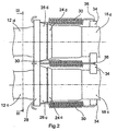
- Manifold 16 comprises four pipe stubs 18a,b,c,d, into which the respective pipes 12a,b,c,d are inserted.
- Stubs 18a,b,c,d lead to a box 20, from which extends a single conduit 22.
- Conduit 22 can be jointed to the terminal parts of the exhaust system.
- both the stub pipes and the conduit extend in substantially parallel directions.
- stub pipes 18a,b,c,d are flared in 24a,b,c,d at their jointing ends.
- Metal gaskets 26a,b,c,d, surrounding pipes 12a,b,c,d, respectively, and having substantially frusto-spherical outside surfaces, are maintained in sealed abutment against the flared ends 24a,b,c,d by elastic means.
- the gaskets might also be made of metal mesh interwoven with synthetic and/or graphite fibers, for enhanced deformability.
- the elastic means comprise a plate 28 with four bores, which receive pipes 12a,b,c,d, and is biased by four helical extension springs 30 to press the bore edges against the gaskets. These are hooked at their ends so that they will hook at one end into slots 32 made near the periphery of plate 28 and, at the other end, into four bridges 34, welded across adjacent pipe stubs and having hook-receiving nicks.
- the frusto-spherical shape of the gaskets helps to maintain a seal in the joints even if the pipes and the pipe stubs should be slightly misaligned.
- gaskets have a preferably frusto-spherical outside surface, which helps to maintain a seal in the joints even if the pipes and the pipe stubs are slightly misaligned, the gaskets might also have a different shape that should turn out to be suitable, such as frusto-conical.
- a larger or smaller number of suitably located helical springs might be used for pressing the plate to abut against the gaskets.
- gaskets might be pressed against the flared pipe ends by means of pairs of opposed rings, one ring acting on the bottom of the gasket, another ring being arranged on the pipe stubs beyond the flared ends, the rings being drawn together by elastic means such as elastic ties or the like.
- the plate may be perforated in order to lighten the exhaust unit.
- the exhaust unit so designed has a fluid mechanical behavior that will optimize the engine's performance.
- the manifold having four pipe stubs joining together into a box from which extends a single conduit avoids sharp direction changes in the exhausted fluid, thereby reducing the flow resistance.
- the length and shape of the pipes can be optimized, based on the several factors affecting the engine's performance and according to the internal hindrances of the vehicle.
- the above exhaust unit has a high degree of adaptability, which enables it to comply with the manufacturing and assembling tolerances of vehicle frames, if one considers that the pipe-manifold connection is longitudinally adjustable, by changing the insertion depth of the pipes into the pipe stubs, and also slight misalignments are absorbed by the frusto-spherical shape of the gaskets.
- Still another advantage of the exhaust unit made as disclosed above is that its cost is comparable with known exhaust units, since it is easy to manufacture and does not require equipment or processes that are not already in use in the industry.
Landscapes
- Engineering & Computer Science (AREA)
- Chemical & Material Sciences (AREA)
- Combustion & Propulsion (AREA)
- Mechanical Engineering (AREA)
- General Engineering & Computer Science (AREA)
- Exhaust Silencers (AREA)
- Cylinder Crankcases Of Internal Combustion Engines (AREA)
- Quick-Acting Or Multi-Walled Pipe Joints (AREA)
- Combustion Methods Of Internal-Combustion Engines (AREA)
Claims (8)
- Abgaseinheit für Brennkraftmaschinen, mit mehreren Rohren (12a, b, c, d), die zum Verbinden mit den Abgasauslässen einer Reihe eines Motors ausgestaltet sind, wobei die Rohre miteinander verbunden werden in einem Krümmer (16) mit einer gleichen Anzahl von Rohrstutzen (18a, b, c, d), von denen jeder eines der Rohre aufnimmt, und wobei die Rohrstutzen zu einer Box (20) führen, aus der sich eine Leitung (22) erstreckt, die mit endseitigen Teilen der Abgaseinheit verbindbar ist, wobei jeder Rohrstutzen an seinem verbundenen Ende ein konisch erweitertes Ende (24a, b, c, d) aufweist, gegen das eine ringförmige Dichtung (26a, b, c, d), die das zugehörige Rohr umgibt, durch elastische Mittel (28, 30, 32, 34, 36) in Anlage gepresst wird.
- Abgaseinheit nach Anspruch 1,
dadurch gekennzeichnet, dass die Rohre (12a, b, c, d) im Wesentlichen gleiche Längen aufweisen. - Abgaseinheit nach Anspruch 1 oder 2,
dadurch gekennzeichnet, dass die elastischen Mittel (28, 30, 32, 34, 36) eine Platte (28) umfassen, die Bohrungen zur Aufnahme der Rohre hat und mit den Bohrungsrändern durch wenigstens eine Schraubenzugfeder (30) gegen die ringförmigen Dichtungen gedrängt wird, wobei die Feder an einem Ende in die Platte und am entgegengesetzten Ende in den Krümmer (16) eingehängt ist. - Abgaseinheit nach einem der vorhergehenden Ansprüche,
dadurch gekennzeichnet, dass der Krümmer (16) wenigstens eine Brücke (34) aufweist, die zum Einhängen der wenigstens einen Schraubenfeder (30) über zwei benachbarte der Rohrstutzen (18a, b, c, d) geschweißt ist. - Abgaseinheit nach einem der vorhergehenden Ansprüche,
dadurch gekennzeichnet, dass die ringförmigen Dichtungen (26a, b, c, d) im Wesentlichen kugelsegmentförmige Außenflächen haben. - Abgaseinheit nach einem der vorhergehenden Ansprüche,
dadurch gekennzeichnet, dass die Rohrstutzen (18a, b, c, d) und die Leitung (22) in im Wesentlichen parallelen Richtungen verlaufen. - Abgaseinheit nach einem der vorhergehenden Ansprüche,
dadurch gekennzeichnet, dass zumindest eines der Rohre (12a, b, c, d) gebogene Abschnitte aufweist, um die Rohrlänge zu vergrößern. - Abgaseinheit nach einem der vorhergehenden Ansprüche,
dadurch gekennzeichnet, dass die Platte (28) mittels Durchbrechungen leichter gemacht ist.
Applications Claiming Priority (3)
| Application Number | Priority Date | Filing Date | Title |
|---|---|---|---|
| IT2001TO000164U ITTO20010164U1 (it) | 2001-09-07 | 2001-09-07 | Gruppo di scarico per motori termici, particolarmente per veicoli ad elevate prestazioni. |
| ITTO20010164U | 2001-09-07 | ||
| PCT/IB2002/003608 WO2003029622A1 (en) | 2001-09-07 | 2002-09-04 | Exhaust unit for engines, particularly for high-performance vehicles |
Publications (2)
| Publication Number | Publication Date |
|---|---|
| EP1425499A1 EP1425499A1 (de) | 2004-06-09 |
| EP1425499B1 true EP1425499B1 (de) | 2005-01-19 |
Family
ID=11458614
Family Applications (1)
| Application Number | Title | Priority Date | Filing Date |
|---|---|---|---|
| EP02762679A Expired - Lifetime EP1425499B1 (de) | 2001-09-07 | 2002-09-04 | Abgaseinheit für brennkraftmaschinen, insbesondere für hochleistungs- kraftfahrzeuge |
Country Status (8)
| Country | Link |
|---|---|
| US (1) | US6931843B2 (de) |
| EP (1) | EP1425499B1 (de) |
| JP (1) | JP2005504221A (de) |
| AT (1) | ATE287491T1 (de) |
| DE (1) | DE60202690T2 (de) |
| ES (1) | ES2236568T3 (de) |
| IT (1) | ITTO20010164U1 (de) |
| WO (1) | WO2003029622A1 (de) |
Families Citing this family (5)
| Publication number | Priority date | Publication date | Assignee | Title |
|---|---|---|---|---|
| US20050173921A1 (en) * | 2004-02-10 | 2005-08-11 | Jerry Roos | Flexible header joint |
| US7665771B2 (en) * | 2004-02-10 | 2010-02-23 | Jerry Roos | Flexible header joint |
| US8695200B2 (en) * | 2011-12-19 | 2014-04-15 | Ford Global Technologies, Llc | Tether for tubes of an exhaust system joint |
| JP6392596B2 (ja) * | 2014-09-11 | 2018-09-19 | 川崎重工業株式会社 | エンジンの排気装置 |
| PL74168Y1 (pl) * | 2023-09-20 | 2025-11-17 | Rm Motors Marek Kodzik Spolka Komandytowa | System montażowy układu wydechowego |
Family Cites Families (7)
| Publication number | Priority date | Publication date | Assignee | Title |
|---|---|---|---|---|
| GB971405A (en) * | 1962-10-19 | 1964-09-30 | Ford Motor Co | Motor vehicle exhaust systems |
| US3670844A (en) | 1971-07-01 | 1972-06-20 | Triple A Accessories | Engine exhaust header construction |
| US5328209A (en) * | 1993-07-20 | 1994-07-12 | Cromwell Steve D | Vehicle exhaust stack joint yieldable in all directions |
| JP3712800B2 (ja) | 1996-09-20 | 2005-11-02 | 本田技研工業株式会社 | 自動二輪車における排気系のカバー装置 |
| US6164067A (en) * | 1997-03-07 | 2000-12-26 | Cronje; Jacobus | Knuckle joint for an exhaust system |
| US6086110A (en) * | 1997-04-10 | 2000-07-11 | Senior Engineering Investments Ag | Vibration decoupling connector for exhaust systems |
| JP3512664B2 (ja) * | 1999-02-22 | 2004-03-31 | 株式会社ユタカ技研 | 多気筒エンジンの排気管集合部 |
-
2001
- 2001-09-07 IT IT2001TO000164U patent/ITTO20010164U1/it unknown
-
2002
- 2002-09-04 EP EP02762679A patent/EP1425499B1/de not_active Expired - Lifetime
- 2002-09-04 ES ES02762679T patent/ES2236568T3/es not_active Expired - Lifetime
- 2002-09-04 DE DE60202690T patent/DE60202690T2/de not_active Expired - Lifetime
- 2002-09-04 JP JP2003532814A patent/JP2005504221A/ja active Pending
- 2002-09-04 AT AT02762679T patent/ATE287491T1/de active
- 2002-09-04 US US10/487,678 patent/US6931843B2/en not_active Expired - Lifetime
- 2002-09-04 WO PCT/IB2002/003608 patent/WO2003029622A1/en not_active Ceased
Also Published As
| Publication number | Publication date |
|---|---|
| EP1425499A1 (de) | 2004-06-09 |
| ITTO20010164U1 (it) | 2003-03-07 |
| ITTO20010164V0 (it) | 2001-09-07 |
| US6931843B2 (en) | 2005-08-23 |
| WO2003029622A1 (en) | 2003-04-10 |
| JP2005504221A (ja) | 2005-02-10 |
| DE60202690D1 (de) | 2005-02-24 |
| ES2236568T3 (es) | 2005-07-16 |
| DE60202690T2 (de) | 2006-01-12 |
| ATE287491T1 (de) | 2005-02-15 |
| US20040194455A1 (en) | 2004-10-07 |
Similar Documents
| Publication | Publication Date | Title |
|---|---|---|
| US4796426A (en) | High efficiency transition element positioned intermediate multi-cylinder exhaust system and secondary pipe assemblies | |
| JPH05118787A (ja) | 複数の管列を有する特に自動車に適する熱交換器 | |
| EP0648922A1 (de) | Luftspaltisolierte gemusterte Abgasleitung für Brennkraftmaschinen | |
| US20070240409A1 (en) | Exhaust manifold flange | |
| EP1425499B1 (de) | Abgaseinheit für brennkraftmaschinen, insbesondere für hochleistungs- kraftfahrzeuge | |
| US5882046A (en) | Dynamic stress controlling flexible hose section | |
| US5327722A (en) | Stamp formed connector for achieving equal length exhaust pipes | |
| US2847819A (en) | Reversible exhaust manifold system | |
| US4831824A (en) | Manifold and manufacturing method thereof | |
| US7770690B2 (en) | Double-flow exhaust system for an internal-combustion engine | |
| EP1149993A1 (de) | Abgassystem einer Fahrzeug-Brennkraftmaschine | |
| US6102446A (en) | Polygonal flexible metal hose coupling assembly | |
| CN1122814C (zh) | 板式换热器 | |
| US7160519B1 (en) | Serviceable exhaust aftertreatment device, and configured cylindrical bodies for coupling | |
| RU72274U1 (ru) | Выпускной коллектор для двигателя внутреннего сгорания | |
| PL330715A1 (en) | Exhaust manifold for internal combustion engines and method of making same | |
| US6488313B1 (en) | Flexible connector assembly for exhaust system | |
| US7582267B1 (en) | Space saving serviceable exhaust aftertreatment assembly | |
| US20060162687A1 (en) | Engine induction system | |
| JP5550388B2 (ja) | エンジンの排気マニホールド構造とその組付方法 | |
| US20090026763A1 (en) | Sliding Sealing Connector | |
| US6103202A (en) | Catalytic converter and pipe assembly | |
| JP2579731Y2 (ja) | 自動車エンジン等のエキゾーストマニホルド | |
| EP1398469B1 (de) | Balganordnung zur Verbindung wenigstens zweier Abgasauslassrohre einer Fahrzeugbrennkraftmaschine mit Abgasrohren und eine Brennkraftmaschine ausgestattet mit einer solchen Anordnung | |
| GB2238004A (en) | Exhaust system. |
Legal Events
| Date | Code | Title | Description |
|---|---|---|---|
| PUAI | Public reference made under article 153(3) epc to a published international application that has entered the european phase |
Free format text: ORIGINAL CODE: 0009012 |
|
| 17P | Request for examination filed |
Effective date: 20030808 |
|
| AK | Designated contracting states |
Kind code of ref document: A1 Designated state(s): AT BE BG CH CY CZ DE DK EE ES FI FR GB GR IE IT LI LU MC NL PT SE SK TR |
|
| AX | Request for extension of the european patent |
Extension state: AL LT LV MK RO SI |
|
| GRAP | Despatch of communication of intention to grant a patent |
Free format text: ORIGINAL CODE: EPIDOSNIGR1 |
|
| RBV | Designated contracting states (corrected) |
Designated state(s): AT DE ES FR GB IT |
|
| GRAS | Grant fee paid |
Free format text: ORIGINAL CODE: EPIDOSNIGR3 |
|
| GRAA | (expected) grant |
Free format text: ORIGINAL CODE: 0009210 |
|
| AK | Designated contracting states |
Kind code of ref document: B1 Designated state(s): AT DE ES FR GB IT |
|
| REG | Reference to a national code |
Ref country code: GB Ref legal event code: FG4D |
|
| REG | Reference to a national code |
Ref country code: IE Ref legal event code: FG4D |
|
| REF | Corresponds to: |
Ref document number: 60202690 Country of ref document: DE Date of ref document: 20050224 Kind code of ref document: P |
|
| REG | Reference to a national code |
Ref country code: ES Ref legal event code: FG2A Ref document number: 2236568 Country of ref document: ES Kind code of ref document: T3 |
|
| PLBE | No opposition filed within time limit |
Free format text: ORIGINAL CODE: 0009261 |
|
| STAA | Information on the status of an ep patent application or granted ep patent |
Free format text: STATUS: NO OPPOSITION FILED WITHIN TIME LIMIT |
|
| ET | Fr: translation filed | ||
| 26N | No opposition filed |
Effective date: 20051020 |
|
| PGFP | Annual fee paid to national office [announced via postgrant information from national office to epo] |
Ref country code: FR Payment date: 20140814 Year of fee payment: 13 Ref country code: ES Payment date: 20140728 Year of fee payment: 13 Ref country code: AT Payment date: 20140902 Year of fee payment: 13 |
|
| REG | Reference to a national code |
Ref country code: AT Ref legal event code: MM01 Ref document number: 287491 Country of ref document: AT Kind code of ref document: T Effective date: 20150904 |
|
| REG | Reference to a national code |
Ref country code: FR Ref legal event code: ST Effective date: 20160531 |
|
| PG25 | Lapsed in a contracting state [announced via postgrant information from national office to epo] |
Ref country code: AT Free format text: LAPSE BECAUSE OF NON-PAYMENT OF DUE FEES Effective date: 20150904 Ref country code: FR Free format text: LAPSE BECAUSE OF NON-PAYMENT OF DUE FEES Effective date: 20150930 |
|
| REG | Reference to a national code |
Ref country code: ES Ref legal event code: FD2A Effective date: 20170131 |
|
| PG25 | Lapsed in a contracting state [announced via postgrant information from national office to epo] |
Ref country code: ES Free format text: LAPSE BECAUSE OF NON-PAYMENT OF DUE FEES Effective date: 20150905 |
|
| PGFP | Annual fee paid to national office [announced via postgrant information from national office to epo] |
Ref country code: GB Payment date: 20190926 Year of fee payment: 18 |
|
| PGFP | Annual fee paid to national office [announced via postgrant information from national office to epo] |
Ref country code: DE Payment date: 20190927 Year of fee payment: 18 |
|
| REG | Reference to a national code |
Ref country code: DE Ref legal event code: R119 Ref document number: 60202690 Country of ref document: DE |
|
| GBPC | Gb: european patent ceased through non-payment of renewal fee |
Effective date: 20200904 |
|
| PG25 | Lapsed in a contracting state [announced via postgrant information from national office to epo] |
Ref country code: DE Free format text: LAPSE BECAUSE OF NON-PAYMENT OF DUE FEES Effective date: 20210401 |
|
| PG25 | Lapsed in a contracting state [announced via postgrant information from national office to epo] |
Ref country code: GB Free format text: LAPSE BECAUSE OF NON-PAYMENT OF DUE FEES Effective date: 20200904 |
|
| PGFP | Annual fee paid to national office [announced via postgrant information from national office to epo] |
Ref country code: IT Payment date: 20210908 Year of fee payment: 20 |