EP1425087B1 - Vorrichtung und verfahren zum bewegen einer flüssigen suspension - Google Patents
Vorrichtung und verfahren zum bewegen einer flüssigen suspension Download PDFInfo
- Publication number
- EP1425087B1 EP1425087B1 EP02733991A EP02733991A EP1425087B1 EP 1425087 B1 EP1425087 B1 EP 1425087B1 EP 02733991 A EP02733991 A EP 02733991A EP 02733991 A EP02733991 A EP 02733991A EP 1425087 B1 EP1425087 B1 EP 1425087B1
- Authority
- EP
- European Patent Office
- Prior art keywords
- vessel
- fluid suspension
- act
- agitating member
- partially flexible
- Prior art date
- Legal status (The legal status is an assumption and is not a legal conclusion. Google has not performed a legal analysis and makes no representation as to the accuracy of the status listed.)
- Expired - Lifetime
Links
- 239000000725 suspension Substances 0.000 title claims abstract description 49
- 239000012530 fluid Substances 0.000 title claims abstract description 48
- 238000000034 method Methods 0.000 title claims abstract description 34
- 230000000284 resting effect Effects 0.000 claims description 8
- 239000000463 material Substances 0.000 description 8
- 235000013361 beverage Nutrition 0.000 description 6
- 239000007788 liquid Substances 0.000 description 6
- 229920002457 flexible plastic Polymers 0.000 description 2
- 235000011389 fruit/vegetable juice Nutrition 0.000 description 2
- 239000011521 glass Substances 0.000 description 2
- 235000015205 orange juice Nutrition 0.000 description 2
- 238000013019 agitation Methods 0.000 description 1
- 239000000203 mixture Substances 0.000 description 1
- 230000002093 peripheral effect Effects 0.000 description 1
- 238000003825 pressing Methods 0.000 description 1
- 230000000717 retained effect Effects 0.000 description 1
- 239000013049 sediment Substances 0.000 description 1
Images


Classifications
-
- B—PERFORMING OPERATIONS; TRANSPORTING
- B01—PHYSICAL OR CHEMICAL PROCESSES OR APPARATUS IN GENERAL
- B01F—MIXING, e.g. DISSOLVING, EMULSIFYING OR DISPERSING
- B01F31/00—Mixers with shaking, oscillating, or vibrating mechanisms
- B01F31/30—Mixers with shaking, oscillating, or vibrating mechanisms comprising a receptacle to only a part of which the shaking, oscillating, or vibrating movement is imparted
- B01F31/31—Mixers with shaking, oscillating, or vibrating mechanisms comprising a receptacle to only a part of which the shaking, oscillating, or vibrating movement is imparted using receptacles with deformable parts, e.g. membranes, to which a motion is imparted
-
- B—PERFORMING OPERATIONS; TRANSPORTING
- B01—PHYSICAL OR CHEMICAL PROCESSES OR APPARATUS IN GENERAL
- B01F—MIXING, e.g. DISSOLVING, EMULSIFYING OR DISPERSING
- B01F31/00—Mixers with shaking, oscillating, or vibrating mechanisms
- B01F31/55—Mixers with shaking, oscillating, or vibrating mechanisms the materials to be mixed being contained in a flexible bag submitted to periodical deformation
-
- B—PERFORMING OPERATIONS; TRANSPORTING
- B01—PHYSICAL OR CHEMICAL PROCESSES OR APPARATUS IN GENERAL
- B01F—MIXING, e.g. DISSOLVING, EMULSIFYING OR DISPERSING
- B01F31/00—Mixers with shaking, oscillating, or vibrating mechanisms
- B01F31/44—Mixers with shaking, oscillating, or vibrating mechanisms with stirrers performing an oscillatory, vibratory or shaking movement
-
- B—PERFORMING OPERATIONS; TRANSPORTING
- B01—PHYSICAL OR CHEMICAL PROCESSES OR APPARATUS IN GENERAL
- B01F—MIXING, e.g. DISSOLVING, EMULSIFYING OR DISPERSING
- B01F35/00—Accessories for mixers; Auxiliary operations or auxiliary devices; Parts or details of general application
- B01F35/30—Driving arrangements; Transmissions; Couplings; Brakes
- B01F35/32—Driving arrangements
- B01F35/325—Driving reciprocating or oscillating stirrers
-
- B—PERFORMING OPERATIONS; TRANSPORTING
- B01—PHYSICAL OR CHEMICAL PROCESSES OR APPARATUS IN GENERAL
- B01F—MIXING, e.g. DISSOLVING, EMULSIFYING OR DISPERSING
- B01F35/00—Accessories for mixers; Auxiliary operations or auxiliary devices; Parts or details of general application
- B01F35/50—Mixing receptacles
- B01F35/513—Flexible receptacles, e.g. bags supported by rigid containers
-
- B—PERFORMING OPERATIONS; TRANSPORTING
- B01—PHYSICAL OR CHEMICAL PROCESSES OR APPARATUS IN GENERAL
- B01F—MIXING, e.g. DISSOLVING, EMULSIFYING OR DISPERSING
- B01F2101/00—Mixing characterised by the nature of the mixed materials or by the application field
- B01F2101/06—Mixing of food ingredients
- B01F2101/14—Mixing of ingredients for non-alcoholic beverages; Dissolving sugar in water
-
- B—PERFORMING OPERATIONS; TRANSPORTING
- B01—PHYSICAL OR CHEMICAL PROCESSES OR APPARATUS IN GENERAL
- B01F—MIXING, e.g. DISSOLVING, EMULSIFYING OR DISPERSING
- B01F2101/00—Mixing characterised by the nature of the mixed materials or by the application field
- B01F2101/06—Mixing of food ingredients
- B01F2101/16—Mixing wine or other alcoholic beverages; Mixing ingredients thereof
Definitions
- This invention relates generally to the beverage industry, and more particularly to an apparatus and method for agitating a fluid suspension so that the fluid suspension is uniformly agitated and mixed, contained in a vessel for dispensing portions of the suspension.
- WO 01/23079 discloses a container used in combination with a flexible plastics bag for agitating liquid contained in the bag.
- the container has a movable internal plunger with a single relative large central opening.
- the container is lined by the flexible plastics bag which is inserted through the opening to contain a liquid to be mixed.
- the plunger is moved up and down below the surface of the liquid to cause an accelerating radially inward flow of liquid below the plunger.
- the converging liquid creates an unrestricted axial flow through the central region of the opening.
- the bag can roll into a peripheral recess in the plunger, and the radial flow can also be created by moving the bottom of the container relative to a fixed internal apertured wall.
- an apparatus used in combination with an at least partially flexible vessel for agitating a fluid suspension contained within such vessel comprising:
- a method for agitating a fluid suspension contained within an at least partially flexible dispensing vessel comprising:
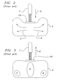
- an actuator 1 reciprocally depresses and releases a bag 2.
- the pressure exerted in the direction 3 by the actuator 1 on plunger 10 forces the suspended material in the bag 2 to travel in directions 4 and 5, away from the center of the bag 2 and towards the sides of the bag 2.
- the actuator releases in a direction 6 the suspended material settles in areas 7 and 8, with little suspended material in area 9.
- beverages dispensed from the bag 2 are not uniform in composition.
- FIG. 4 through 8 illustrate an apparatus for agitating a fluid suspension 20 contained within an at least partially flexible vessel 30.
- the at least partially flexible vessel 30 is completely flexible.
- the apparatus has a structure 40 for receiving the at least partially flexible vessel 30.
- the structure 40 is temperature controlled using any device or method that is well known in the art.
- the structure 40 may be refrigerated or heated. As shown in Figs.
- the structure has a panel 42 that is suitably adjustable between a first, open, loading position shown in Fig. 4, where the vessel may be conveniently removed from or inserted into the structure 40, and a second, closed, operating position, shown in Fig. 6, where the vessel 30 is retained within the structure 40 in a position suitable for an agitating member 50 to substantially uniformly agitate the fluid suspension.
- hinges 46 permit the panel, or door, 42 to be moved between the first loading position and the second operating position.
- the structure 40 has an agitating member 50 operatively located within the structure 40, and the agitating member 50 is suitably movable in an arcuate path between a first position, proximate first end 60 of arcuate slot 65 in structure 40, and a second position proximate second end 70 of said slot 65.
- the at least partially flexible vessel 30 is conveniently positioned such that a first inner portion 80 rests substantially proximate to a first side 100 of the agitating member 50.
- a second inner portion 90 of the at least partially flexible vessel 30 rests substantially proximate to a second side 110 of the agitating member 50.
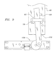
- a motor 120 herein illustrated by a schematic representation representing any device to impart motion known in the art, including motion imparted through manual operation, is operatively communicated to the agitating member 50.
- the motor 120 operatively communicates with the agitating member 50 through a linkage 170.
- Figure 8 illustrates a preferred motor 122 and a preferred linkage 172.
- Figure 9 illustrates the linkage 172 from a side view.
- the motor 120 suitably causes the agitating member 50 to move between the first position and the second position to substantially uniformly agitate the fluid suspension 20.
- the motor 122 imparts reciprocal motion to the agitating member 50 by moving the linkage 172 and agitating motion to a first position 60 and a second position 70.
- the structure 40 defines an inner portion 124 of the structure and an outer portion generally represented by the reference numeral 130.
- a passage 150 is disposed between the inner portion 124 and the outer portion 130 of the structure 40.
- the passage 150 is utilized in dispensing the fluid suspension 20 from the inner portion 124 to the outer portion 130 of the structure 40.
- the at least partially flexible vessel 30 suitably has a dispensing tube 160 that is operatively associated with the passage 150 for dispensing the fluid suspension 20 from the inner portion 124 to the outer portion 130 of the structure 40.
- the at least partially flexible vessel 30 is folded such that there is an inner first portion 80 and an inner second portion 90.
- the agitating member 50 reciprocally moves the inner first portion 80 between a first position, shown in Fig. 11, and a second position, shown in Fig. 12.
- the agitating member 50 also reciprocally moves the inner second portion 90 between a first position, shown in Fig. 11, and a second position shown in Fig. 12. This reciprocal motion conveniently substantially uniformly agitates the fluid suspension 20.
- Figs. 5, 11, 12, and 13 also illustrate the manner in which a preferred apparatus 10 and method 269 of this invention substantially uniformly agitates the fluid suspension 20.
- the agitating member 50 exerts a force in the direction of reference number 180 on the inner first portion 80 of the at least partially flexible vessel 30, causing the inner first portion to travel to the first position, shown in Fig. 11.
- This movement causes the fluid suspension 20 to travel in a direction generally shown by the arrow of reference numeral 250.
- the inner second portion 90 of the at least partially flexible vessel 30 travels to the illustrated first position.
- the agitating member then exerts a force in the direction of reference number 190 on the inner second portion 90 of the at least partially flexible vessel 30, causing the inner second portion 90 to reciprocally move from the first position illustrated in Fig. 11 to the second position illustrated in Fig. 12.
- the inner first portion 80 reciprocally moves from the illustrated first position to the second position.
- the fluid suspension 20 preferably travels in a direction generally shown by the arrow of reference numeral 260. As a result of this reciprocal motion, the fluid suspension is substantially uniformly agitated.
- the at least partially flexible vessel 30 is loaded into a structure 40 for dispensing the fluid suspension 40.
- Structure 40 suitably defines an inner portion 124 and an outer portion 130 and has a passage disposed between the inner portion 124 and the outer portion 130 of the structure 40.
- a preferred method of this invention temperature controls the structure 40.
- the at least partially flexible vessel 30 loaded into the structure 40 has a dispensing tube 160.
- a user of a method of this invention operatively associates the dispensing tube 160 with the passage 150 of the structure 40.
- the fluid suspension is dispensed from the structure 40.
- an act 270 is folding an at least partially flexible vessel such that there is an inner first portion and an inner second portion.
- another act 280 is reciprocally moving said inner first portion between a first position and a second position, whereby said fluid suspension is substantially uniformly agitated within said at least partially flexible vessel.
- FIG. 14 illustrates another preferred method 289 of the present invention.
- An act 290 is, preferably, folding an at least partially flexible vessel having a dispensing tube such that there is an inner first portion and an inner second portion.
- Another convenient act 300 is loading the vessel into a structure.
- this structure defines an inner portion of the structure, an outer portion of the structure, and a passage disposed between the inner portion and the outer portion for dispensing a fluid suspension.
- an act 310 is reciprocally moving the inner first portion between a first position and a second position; whereby the fluid suspension is substantially uniformly agitated within the at least partially flexible vessel.
- An act 320 is reciprocally moving the inner second portion of the vessel between a first position and a second position.
- another act 330 is temperature controlling the structure by any device or method well known in the art.
- An act 340 is operatively associating the dispensing tube of the vessel and the passage of the structure.
- an act 350 is dispensing the fluid suspension. It should be noted that these are acts for one preferred embodiment of the present invention, and the actual order of the steps is not critical to the invention.
Claims (21)
- Vorrichtung, die in Kombination mit einem wenigstens teilweise flexiblen Gefäß zum Bewegen einer in einem solchen Gefäß gehaltenen Fluidsuspension verwendet wird und folgendes umfaßt:ein Gefäß (30), welches wenigstens teilweise flexibel ist,eine Struktur (40) für das Aufnehmen des wenigstens teilweise flexiblen Gefäßes,ein Bewegungselement (50), welches eine erste Seite und eine gegenüberliegende zweite Seite hat und auf einer bogenförmigen Bahn um eine Drehachse zwischen einer ersten Position und einer zweiten Position verschwenkbar bewegt werden kann und innerhalb der Struktur funktionsfähig so angeordnet ist, daß das Gefäß so aufgenommen werden kann, daß ein innerer erster Teil des Gefäßes über einer ersten Seite des Bewegungselements liegt und sich unmittelbar darauf abstützt, und ein innerer zweiter Teil des Gefäßes über einer zweiten Seite des Bewegungselements liegt und sich unmittelbar darauf abstützt, undeinen Motor (122), der funktionsfähig mit dem Bewegungselement kommuniziert, wobei das Bewegungselement sich zwischen der ersten Position und der zweiten Position hin- und herbewegt, um die Fluidsuspension im wesentlichen einheitlich zu bewegen.
- Vorrichtung nach Anspruch 1, wobei die Struktur (40) temperaturgesteuert ist.
- Vorrichtung nach Anspruch 1 oder 2, wobei die Struktur (40) eine Platte (42) beinhaltet, die zwischen einer ersten Beladeposition und einer zweiten Betriebsposition einstellbar ist.
- Vorrichtung nach Anspruch 1, 2 oder 3, wobei das Gefäß (30) vollständig flexibel ist.
- Vorrichtung nach Anspruch 1, 2, 3 oder 4, wobei die Struktur (40) einen inneren Bereich der Struktur und einen äußeren Bereich der Struktur definiert und ein Durchgang (150) zwischen dem inneren Bereich und dem äußeren Bereich angeordnet ist, um die Fluidsuspension aus dem inneren Bereich an den äußeren Bereich abzugeben.
- Vorrichtung nach Anspruch 5, wobei das wenigstens teilweise flexible Gefäß (30) einen Abgabeschlauch (160) aufweist.
- Vorrichtung nach Anspruch 6, wobei der Durchgang (150) und der Abgabeschlauch (160) funktionsfähig miteinander verbunden sind, um die Fluidsuspension aus dem inneren Bereich an den äußeren Bereich abzugeben.
- Vorrichtung nach Anspruch 1, wobei das Gefäß (30) einen Abgabeschlauch (160) aufweist.
- Vorrichtung nach einem der vorangegangenen Ansprüche, wobei der Motor (122) durch ein Verbindungselement (170) funktionsfähig mit dem Bewegungselement (50) kommuniziert.
- Verfahren zum Bewegen einer Fluidsuspension, die in einem wenigstens teilweise flexiblen Abgabegefäß (30) enthalten ist, wobei das Verfahren folgendes umfaßt:Falten des Gefäßes um ein Bewegungselement (50), welches einander gegenüberliegende erste und zweite Seiten hat und auf einer bogenförmigen Bahn um eine Drehachse zwischen einer ersten Position und einer zweiten Position verschwenkbar bewegt werden kann, so daß das Gefäß in der Weise aufgenommen wird, daß ein innerer erster Teil des Gefäßes über der ersten Seite des Bewegungselements liegt und sich unmittelbar darauf abstützt und ein innerer zweiter Teil des Gefäßes über der zweiten Seite des Bewegungselements liegt und sich unmittelbar darauf abstützt, undHin- und Herbewegen des Bewegungselements (50) um die Drehachse auf der bogenförmigen Bahn zwischen der ersten Position und der zweiten Position, wobei die Fluidsuspension in dem Gefäß im wesentlichen einheitlich bewegt wird.
- Verfahren nach Anspruch 10, welches weiterhin den Vorgang des Hin- und Herbewegens des inneren zweiten Teils zwischen einer ersten Position und einer zweiten Position umfaßt.
- Verfahren nach Anspruch 10 oder 11, welches weiterhin den Vorgang des Ladens des wenigstens teilweise flexiblen Gefäßes in eine Struktur (40) umfaßt.
- Verfahren nach Anspruch 10, 11 oder 12, welches weiterhin den Vorgang des Abgebens der Fluidsuspension umfaßt.
- Verfahren nach Anspruch 10, welches weiterhin den Vorgang des Ladens des wenigstens teilweise flexiblen Gefäßes in eine Aufnahmestruktur (40) umfaßt.
- Verfahren nach einem der Ansprüche 13 oder 14, welches weiterhin den Vorgang der Temperatursteuerung der Struktur umfaßt.
- Verfahren nach Anspruch 10, 11, 12 oder 13, welches weiterhin den Vorgang der Temperatursteuerung der Struktur umfaßt.
- Verfahren nach einem der Ansprüche 10 bis 16, welches weiterhin den Vorgang des Abgebens der Fluidsuspension umfaßt.
- Verfahren nach Anspruch 10, welches weiterhin den Vorgang des Ladens des wenigstens teilweise flexiblen Gefäßes (30) in eine Aufnahmestruktur (40) umfaßt, wobei die Struktur einen inneren Bereich der Struktur und einen äußeren Bereich der Struktur und einen Durchgang (150) definiert, welcher zwischen dem inneren Bereich und dem äußeren Bereich angeordnet ist, um die Fluidsuspension abzugeben.
- Verfahren nach Anspruch 18, welches weiterhin den Vorgang des Ladens eines wenigstens teilweise flexiblen Gefäßes mit einem Abgabeschlauch (160) in die Struktur umfaßt.
- Verfahren nach Anspruch 19, welches weiterhin den Vorgang des funktionsfähigen Verbindens des Abgabeschlauchs (160) und des Durchgangs (150) umfaßt.
- Verfahren nach Anspruch 20, welches weiterhin den Vorgang des Abgebens der Fluidsuspension umfaßt.
Applications Claiming Priority (3)
| Application Number | Priority Date | Filing Date | Title |
|---|---|---|---|
| US925998 | 1997-09-09 | ||
| US09/925,998 US6634783B2 (en) | 2001-08-09 | 2001-08-09 | Apparatus for agitating a fluid suspension |
| PCT/US2002/011902 WO2003013713A1 (en) | 2001-08-09 | 2002-06-11 | Apparatus and method for agitating a fluid suspension |
Publications (3)
| Publication Number | Publication Date |
|---|---|
| EP1425087A1 EP1425087A1 (de) | 2004-06-09 |
| EP1425087A4 EP1425087A4 (de) | 2006-04-26 |
| EP1425087B1 true EP1425087B1 (de) | 2007-10-17 |
Family
ID=25452574
Family Applications (1)
| Application Number | Title | Priority Date | Filing Date |
|---|---|---|---|
| EP02733991A Expired - Lifetime EP1425087B1 (de) | 2001-08-09 | 2002-06-11 | Vorrichtung und verfahren zum bewegen einer flüssigen suspension |
Country Status (6)
| Country | Link |
|---|---|
| US (2) | US6634783B2 (de) |
| EP (1) | EP1425087B1 (de) |
| AT (1) | ATE375820T1 (de) |
| DE (1) | DE60223057T2 (de) |
| NO (1) | NO331141B1 (de) |
| WO (1) | WO2003013713A1 (de) |
Families Citing this family (47)
| Publication number | Priority date | Publication date | Assignee | Title |
|---|---|---|---|---|
| US7086778B2 (en) * | 2000-10-09 | 2006-08-08 | Levtech, Inc. | System using a levitating, rotating pumping or mixing element and related methods |
| WO2003012027A1 (de) * | 2001-07-31 | 2003-02-13 | Ursula Erhardt | Bioreaktor mit einer apparatur mit flexiblen wandungen |
| US6923567B2 (en) * | 2002-04-12 | 2005-08-02 | Hynetics Llc | Mixing tank assembly |
| EP1352684A3 (de) * | 2002-04-12 | 2005-04-27 | Hynetics, LLC | Verfahren zur Mischung von Lösungen |
| US6908223B2 (en) | 2002-04-12 | 2005-06-21 | Hynetics Llc | Systems for mixing liquid solutions and methods of manufacture |
| US6981794B2 (en) * | 2002-04-12 | 2006-01-03 | Hynetics Llc | Methods for mixing solutions |
| DE60311981T2 (de) * | 2002-04-26 | 2007-09-06 | Navigant Biotechnologies, Inc., Lakewood | Vorrichtung zur bestrahlung und mischung von fluiden in behältern |
| US6837610B2 (en) * | 2002-09-27 | 2005-01-04 | Ilc Dover Lpp | Bioprocess container, bioprocess container mixing device and method of use thereof |
| WO2004087320A2 (en) * | 2003-03-28 | 2004-10-14 | Hyclone Laboratories, Inc. | Fluid dispensing bins and related methods |
| US7377686B2 (en) * | 2003-09-04 | 2008-05-27 | Millipore Corporation | Disposable mixing system |
| US7249880B2 (en) | 2003-10-14 | 2007-07-31 | Advanced Technology Materials, Inc. | Flexible mixing bag for mixing solids, liquids and gases |
| EP1737563B1 (de) * | 2004-03-08 | 2008-12-24 | Seward Limited | Vorrichtung und verfahren zum mischen von materialien in beuteln |
| US20050249033A1 (en) * | 2004-05-04 | 2005-11-10 | Krause Richard J | Disposable reciprocating bag mixing systems |
| EP1896164B1 (de) * | 2005-06-23 | 2012-02-08 | Koninklijke Philips Electronics N.V. | Vorrichtung zur mischung eines flüssigmediums |
| CA2627654C (en) * | 2005-10-26 | 2012-02-07 | Levtech, Inc. | Bioreactor with mixer and sparger |
| ATE420040T1 (de) * | 2006-03-29 | 2009-01-15 | Jobmann Wolfgang Gmbh | Getränkebeutel mit einer beweglichen tasche für einen dispenser |
| EP2010310A4 (de) | 2006-04-21 | 2010-03-31 | Advanced Tech Materials | Systeme und vorrichtung zur mischung von substanzen und herstellungsverfahren dafür |
| DE102006020813B3 (de) * | 2006-05-03 | 2007-10-04 | Sartorius Biotech Gmbh | Behälteranordnung mit einem Behälter mit flexibler Wandung |
| SG10201503987WA (en) * | 2006-05-13 | 2015-06-29 | Pall Life Sciences Belgium | Disposable Bioreactor |
| US8177415B1 (en) * | 2006-07-24 | 2012-05-15 | Tarpaulin.Com, Inc. | System for agitating pouched products |
| US8070354B2 (en) * | 2007-02-05 | 2011-12-06 | Bungay Iii Henry Robert | Systems and methods for mixing bioprocessing materials |
| US7740212B2 (en) * | 2008-04-17 | 2010-06-22 | ConeCraft, Inc, | Apparatus to retain and position tubing of media bags |
| US8535936B2 (en) * | 2008-06-30 | 2013-09-17 | Twistaferm | Vessels for mixing bioprocessing materials |
| US11325286B2 (en) * | 2009-09-24 | 2022-05-10 | Sealed Air Corporation (Us) | Mixing machine for producing foam within a bag |
| WO2011038212A1 (en) * | 2009-09-24 | 2011-03-31 | Sealed Air Corporation (Us) | Machine for producing foam within a bag |
| EP2374541A1 (de) * | 2010-04-06 | 2011-10-12 | Symbion Medical Systems Sàrl | Einweg-Ausgabekartusche für medizinische Testgeräte |
| US9522980B2 (en) | 2010-05-06 | 2016-12-20 | Johnson & Johnson Vision Care, Inc. | Non-reactive, hydrophilic polymers having terminal siloxanes and methods for making and using the same |
| US9170349B2 (en) | 2011-05-04 | 2015-10-27 | Johnson & Johnson Vision Care, Inc. | Medical devices having homogeneous charge density and methods for making same |
| US20120283381A1 (en) | 2011-05-04 | 2012-11-08 | Ryuta Tamiya | Macroinitiator containing hydrophobic segment |
| US20130203813A1 (en) | 2011-05-04 | 2013-08-08 | Johnson & Johnson Vision Care, Inc. | Medical devices having homogeneous charge density and methods for making same |
| US8746506B2 (en) | 2011-05-26 | 2014-06-10 | Pepsico, Inc. | Multi-tower modular dispensing system |
| US8985396B2 (en) | 2011-05-26 | 2015-03-24 | Pepsico. Inc. | Modular dispensing system |
| US9376655B2 (en) | 2011-09-29 | 2016-06-28 | Life Technologies Corporation | Filter systems for separating microcarriers from cell culture solutions |
| US9138496B2 (en) * | 2012-04-18 | 2015-09-22 | Allosource | Systems and methods for cleaning and disinfecting allograft material |
| EP2855545B1 (de) | 2012-05-25 | 2017-11-01 | Johnson & Johnson Vision Care Inc. | Polymere und nanogelmaterialien sowie verfahren zur herstellung und verwendung davon |
| US10073192B2 (en) | 2012-05-25 | 2018-09-11 | Johnson & Johnson Vision Care, Inc. | Polymers and nanogel materials and methods for making and using the same |
| US9297929B2 (en) | 2012-05-25 | 2016-03-29 | Johnson & Johnson Vision Care, Inc. | Contact lenses comprising water soluble N-(2 hydroxyalkyl) (meth)acrylamide polymers or copolymers |
| US9244196B2 (en) | 2012-05-25 | 2016-01-26 | Johnson & Johnson Vision Care, Inc. | Polymers and nanogel materials and methods for making and using the same |
| DE102012012887A1 (de) * | 2012-06-28 | 2014-01-02 | Wmf Württembergische Metallwarenfabrik Ag | Mischvorrichtung zum Vermischen einesLebensmittelkonzentrats mit einer Flüssigkeit |
| FR2997703B1 (fr) * | 2012-11-07 | 2016-12-30 | Biomerieux Sa | Procede de traitement d'au moins un echantillon biologique |
| US8979357B1 (en) * | 2014-03-17 | 2015-03-17 | Advanced Scientifics, Inc. | Transportable mixing system for biological and pharmaceutical materials |
| US9475100B2 (en) | 2014-09-19 | 2016-10-25 | Allosource | Systems and methods for cleaning and disinfecting allograft material |
| US10759584B2 (en) | 2018-03-02 | 2020-09-01 | Life Technologies Corporation | System for port and tube holder assembly attachment device and methods of use |
| WO2020011818A1 (en) * | 2018-07-12 | 2020-01-16 | Merck Patent Gmbh | Mixing device |
| FR3090400B1 (fr) * | 2018-12-21 | 2023-03-31 | Seb Sa | Appareil de fabrication, machine à mélange et/ou dispositif de réception pour la fabrication d’une composition à partir d’un mélange de formulations |
| CN113260276A (zh) * | 2019-01-03 | 2021-08-13 | 宝洁公司 | 个性化皮肤护理系统 |
| CN114192006A (zh) * | 2021-11-19 | 2022-03-18 | 海南海灵化学制药有限公司 | 一种移动式药品调配台 |
Family Cites Families (35)
| Publication number | Priority date | Publication date | Assignee | Title |
|---|---|---|---|---|
| US1437880A (en) * | 1922-05-17 | 1922-12-05 | Joseph Baker Sons & Perkins | Machine for use in the manufacture of confectionery |
| US2235942A (en) * | 1938-12-17 | 1941-03-25 | Earl C Brownell | Sacking machine |
| US2336438A (en) * | 1942-03-06 | 1943-12-07 | Scovill Manufacturing Co | Apparatus for mixing powdered materials |
| US2356004A (en) * | 1942-10-05 | 1944-08-15 | Walter C Hoy | Shaker |
| US2419330A (en) * | 1943-05-13 | 1947-04-22 | Gen Mills Inc | Compacting flour in bags |
| US2406535A (en) * | 1944-06-14 | 1946-08-27 | Remington Arms Co Inc | Mixing machine |
| US2462286A (en) * | 1944-08-19 | 1949-02-22 | St Regis Paper Co | Bag packer and weigher with jigging device |
| US3096081A (en) * | 1959-11-09 | 1963-07-02 | Bemis Bro Bag Co | Bag former and shaker |
| US3132848A (en) * | 1961-05-22 | 1964-05-12 | Garlinghouse Brothers | Quick mixer |
| US3211432A (en) * | 1962-04-23 | 1965-10-12 | R Dental Products Inc Van | Vibrating table construction |
| US3499578A (en) | 1966-01-12 | 1970-03-10 | Universal Match Corp | Beverage dispensing systems |
| DE1902200B1 (de) * | 1969-01-17 | 1970-11-26 | Ernst Huebers | Vorrichtung zum Mischen von Stoffen |
| US3740028A (en) * | 1969-09-11 | 1973-06-19 | A Bodine | Inductive cavitator |
| US3819158A (en) * | 1972-08-17 | 1974-06-25 | Lever Brothers Ltd | Devices for blending materials |
| US3833203A (en) * | 1973-03-09 | 1974-09-03 | Garlinghouse Brothers Mfg Inc | Flexible mixer discharge |
| CH620403A5 (de) * | 1977-11-01 | 1980-11-28 | Sig Schweiz Industrieges | |
| SE8207438D0 (sv) | 1982-12-28 | 1982-12-28 | Gunnar Hedenberg | Sett for tillverkning av matvaruprodukter sasom brod, kakor och liknande och bakautomat for tillverkning av sagda produkter |
| US4550654A (en) * | 1983-04-01 | 1985-11-05 | Heden Team A.G. | Apparatus for automatic preparation of food products such as bread, cakes and the like |
| US4590850A (en) * | 1983-12-27 | 1986-05-27 | Heden Team A.G. | Apparatus for automatically making of food products such as bread, cakes and the like |
| AT393771B (de) * | 1985-12-23 | 1991-12-10 | Heden Team Ag | Vorrichtung und verfahren zur automatischen herstellung von lebens- bzw. nahrungsmitteln in stueckform aus teigartigen substanzen |
| EP0237260B1 (de) | 1986-03-10 | 1989-12-20 | Solly Katz | Ausgeber für Flüssigkeiten |
| GB8618533D0 (en) * | 1986-07-30 | 1986-09-10 | Johnsen Jorgensen Jaypak | Form of mixing bag |
| US5121857A (en) | 1988-07-16 | 1992-06-16 | Corrugated Products Limited | Agitating and dispensing arrangement for bag-in-box containers |
| ZA896453B (en) * | 1988-09-08 | 1990-05-30 | Katz Solly | A fluid dispenser |
| GB2230251A (en) * | 1989-03-23 | 1990-10-17 | Michael Bell | Bag arrangement for reconstituting powdered milk and the like |
| US5141135A (en) | 1990-12-18 | 1992-08-25 | Beta Raven Inc. | Bracket assembly for agitating a bag containing bulk dry material |
| IT1268395B1 (it) * | 1994-03-09 | 1997-02-27 | Bocon | Dispositivo per congelare o surgelare prodotti alimentari |
| GB9525184D0 (en) * | 1995-12-08 | 1996-02-07 | Bhr Group Ltd | Mixing apparatus |
| US5699902A (en) * | 1996-04-03 | 1997-12-23 | Sperry; Laurence Burst | Foam in bag packaging system |
| US6272813B1 (en) * | 1996-04-03 | 2001-08-14 | Sealed Air Corporation | Foam in bag packaging system |
| WO1997043039A1 (en) * | 1996-05-13 | 1997-11-20 | Filtaflex Limited | Bag beating microbe suspender with vibrating beater |
| US6186360B1 (en) | 1998-11-20 | 2001-02-13 | Schenck Accurate, Inc. | Machine and method for unloading a bulk-material bag |
| CA2265014A1 (en) | 1999-03-05 | 2000-09-05 | Labplas Inc. | Device for blending contents of a bag |
| GB9905312D0 (en) * | 1999-03-09 | 1999-04-28 | Rodgers Christopher R | Mixing method and apparatus |
| GB9922682D0 (en) * | 1999-09-25 | 1999-11-24 | Rogers Christopher R | Mixing apparatus and method |
-
2001
- 2001-08-09 US US09/925,998 patent/US6634783B2/en not_active Expired - Lifetime
-
2002
- 2002-06-11 EP EP02733991A patent/EP1425087B1/de not_active Expired - Lifetime
- 2002-06-11 DE DE60223057T patent/DE60223057T2/de not_active Expired - Lifetime
- 2002-06-11 AT AT02733991T patent/ATE375820T1/de not_active IP Right Cessation
- 2002-06-11 WO PCT/US2002/011902 patent/WO2003013713A1/en active IP Right Grant
- 2002-09-27 US US10/256,433 patent/US6637929B2/en not_active Expired - Lifetime
-
2004
- 2004-02-06 NO NO20040554A patent/NO331141B1/no not_active IP Right Cessation
Also Published As
| Publication number | Publication date |
|---|---|
| US6637929B2 (en) | 2003-10-28 |
| ATE375820T1 (de) | 2007-11-15 |
| NO20040554L (no) | 2004-02-27 |
| DE60223057T2 (de) | 2008-07-24 |
| EP1425087A4 (de) | 2006-04-26 |
| WO2003013713A1 (en) | 2003-02-20 |
| US20030031085A1 (en) | 2003-02-13 |
| EP1425087A1 (de) | 2004-06-09 |
| DE60223057D1 (de) | 2007-11-29 |
| US20030031088A1 (en) | 2003-02-13 |
| NO20040554D0 (no) | 2004-02-06 |
| US6634783B2 (en) | 2003-10-21 |
| NO331141B1 (no) | 2011-10-24 |
Similar Documents
| Publication | Publication Date | Title |
|---|---|---|
| EP1425087B1 (de) | Vorrichtung und verfahren zum bewegen einer flüssigen suspension | |
| JP3492974B2 (ja) | 着色化粧品の包装および分配を行うポータブルディスペンサ | |
| US6148874A (en) | Filling head mechanism that removes material from a spout of a filled container before completely disengaging from the spout | |
| EP2266689B1 (de) | Vorrichtung zur Ausgabe von mehreren Materialien | |
| US3041052A (en) | Paint mixing and blending apparatus | |
| US5000353A (en) | Dosing and dispensing device | |
| US5713263A (en) | Wine aerator | |
| JP3712731B2 (ja) | 第1及び第2の製品を容器に充填するための包装機の充填装置 | |
| EP0391286A1 (de) | Automatische Abgabeeinheit für Tintenpaste oder ähnliches | |
| US6149034A (en) | Paste dispenser | |
| US5934344A (en) | Printing ink storage container and associated dispensing apparatus | |
| US6662975B1 (en) | Apparatus and a method for metering liquids | |
| AU625836B2 (en) | A method of and an apparatus for venting a filling plant | |
| EP0745342B1 (de) | Flüssigkeitsspender für zwei Produkten | |
| US4982770A (en) | Apparatus for filling specified amount of liquid | |
| GB2118054A (en) | Dispensing device for a paint mixing machine | |
| US2065095A (en) | Process and apparatus for dispensing pastes | |
| JP2002019886A (ja) | 飲料混合装置および飲料提供装置 | |
| AU612888B2 (en) | System for dispensing liquid from a paperboard carton | |
| JPS63209740A (ja) | 撹拌乳化機 | |
| JP3268510B2 (ja) | 軟性容器内の液体混合手段付きの液体定量抽出ディスペンサー | |
| US5468067A (en) | Method for mixing liquid media having different specific weights | |
| KR0165974B1 (ko) | 냉장고용 커피 믹서기 교반 장치 | |
| US6028166A (en) | Method and apparatus for generating a continuous source of mixed and degassed resin | |
| JPH03226490A (ja) | 貯蔵容器からの液体配量注出装置 |
Legal Events
| Date | Code | Title | Description |
|---|---|---|---|
| PUAI | Public reference made under article 153(3) epc to a published international application that has entered the european phase |
Free format text: ORIGINAL CODE: 0009012 |
|
| 17P | Request for examination filed |
Effective date: 20040309 |
|
| AK | Designated contracting states |
Kind code of ref document: A1 Designated state(s): AT BE CH CY DE DK ES FI FR GB GR IE IT LI LU MC NL PT SE TR |
|
| AX | Request for extension of the european patent |
Extension state: AL LT LV MK RO SI |
|
| RAP1 | Party data changed (applicant data changed or rights of an application transferred) |
Owner name: VITALITY FOODSERVICE, INC. |
|
| A4 | Supplementary search report drawn up and despatched |
Effective date: 20060313 |
|
| RIC1 | Information provided on ipc code assigned before grant |
Ipc: B01F 11/00 20060101AFI20030226BHEP Ipc: A23L 2/00 20060101ALI20060307BHEP Ipc: B01F 15/00 20060101ALI20060307BHEP |
|
| 17Q | First examination report despatched |
Effective date: 20060712 |
|
| GRAP | Despatch of communication of intention to grant a patent |
Free format text: ORIGINAL CODE: EPIDOSNIGR1 |
|
| GRAS | Grant fee paid |
Free format text: ORIGINAL CODE: EPIDOSNIGR3 |
|
| GRAA | (expected) grant |
Free format text: ORIGINAL CODE: 0009210 |
|
| AK | Designated contracting states |
Kind code of ref document: B1 Designated state(s): AT BE CH CY DE DK ES FI FR GB GR IE IT LI LU MC NL PT SE TR |
|
| REG | Reference to a national code |
Ref country code: GB Ref legal event code: FG4D |
|
| REG | Reference to a national code |
Ref country code: CH Ref legal event code: EP |
|
| REG | Reference to a national code |
Ref country code: IE Ref legal event code: FG4D |
|
| REF | Corresponds to: |
Ref document number: 60223057 Country of ref document: DE Date of ref document: 20071129 Kind code of ref document: P |
|
| PG25 | Lapsed in a contracting state [announced via postgrant information from national office to epo] |
Ref country code: LI Free format text: LAPSE BECAUSE OF FAILURE TO SUBMIT A TRANSLATION OF THE DESCRIPTION OR TO PAY THE FEE WITHIN THE PRESCRIBED TIME-LIMIT Effective date: 20071017 Ref country code: SE Free format text: LAPSE BECAUSE OF FAILURE TO SUBMIT A TRANSLATION OF THE DESCRIPTION OR TO PAY THE FEE WITHIN THE PRESCRIBED TIME-LIMIT Effective date: 20080117 Ref country code: CH Free format text: LAPSE BECAUSE OF FAILURE TO SUBMIT A TRANSLATION OF THE DESCRIPTION OR TO PAY THE FEE WITHIN THE PRESCRIBED TIME-LIMIT Effective date: 20071017 Ref country code: ES Free format text: LAPSE BECAUSE OF FAILURE TO SUBMIT A TRANSLATION OF THE DESCRIPTION OR TO PAY THE FEE WITHIN THE PRESCRIBED TIME-LIMIT Effective date: 20080128 |
|
| REG | Reference to a national code |
Ref country code: CH Ref legal event code: PL |
|
| PG25 | Lapsed in a contracting state [announced via postgrant information from national office to epo] |
Ref country code: PT Free format text: LAPSE BECAUSE OF FAILURE TO SUBMIT A TRANSLATION OF THE DESCRIPTION OR TO PAY THE FEE WITHIN THE PRESCRIBED TIME-LIMIT Effective date: 20080317 |
|
| PG25 | Lapsed in a contracting state [announced via postgrant information from national office to epo] |
Ref country code: AT Free format text: LAPSE BECAUSE OF FAILURE TO SUBMIT A TRANSLATION OF THE DESCRIPTION OR TO PAY THE FEE WITHIN THE PRESCRIBED TIME-LIMIT Effective date: 20071017 |
|
| ET | Fr: translation filed | ||
| PG25 | Lapsed in a contracting state [announced via postgrant information from national office to epo] |
Ref country code: DK Free format text: LAPSE BECAUSE OF FAILURE TO SUBMIT A TRANSLATION OF THE DESCRIPTION OR TO PAY THE FEE WITHIN THE PRESCRIBED TIME-LIMIT Effective date: 20071017 |
|
| PLBE | No opposition filed within time limit |
Free format text: ORIGINAL CODE: 0009261 |
|
| STAA | Information on the status of an ep patent application or granted ep patent |
Free format text: STATUS: NO OPPOSITION FILED WITHIN TIME LIMIT |
|
| PG25 | Lapsed in a contracting state [announced via postgrant information from national office to epo] |
Ref country code: BE Free format text: LAPSE BECAUSE OF FAILURE TO SUBMIT A TRANSLATION OF THE DESCRIPTION OR TO PAY THE FEE WITHIN THE PRESCRIBED TIME-LIMIT Effective date: 20071017 |
|
| 26N | No opposition filed |
Effective date: 20080718 |
|
| PG25 | Lapsed in a contracting state [announced via postgrant information from national office to epo] |
Ref country code: GR Free format text: LAPSE BECAUSE OF FAILURE TO SUBMIT A TRANSLATION OF THE DESCRIPTION OR TO PAY THE FEE WITHIN THE PRESCRIBED TIME-LIMIT Effective date: 20080118 Ref country code: MC Free format text: LAPSE BECAUSE OF NON-PAYMENT OF DUE FEES Effective date: 20080630 |
|
| PG25 | Lapsed in a contracting state [announced via postgrant information from national office to epo] |
Ref country code: FI Free format text: LAPSE BECAUSE OF FAILURE TO SUBMIT A TRANSLATION OF THE DESCRIPTION OR TO PAY THE FEE WITHIN THE PRESCRIBED TIME-LIMIT Effective date: 20071017 |
|
| PG25 | Lapsed in a contracting state [announced via postgrant information from national office to epo] |
Ref country code: IE Free format text: LAPSE BECAUSE OF NON-PAYMENT OF DUE FEES Effective date: 20080611 |
|
| PG25 | Lapsed in a contracting state [announced via postgrant information from national office to epo] |
Ref country code: CY Free format text: LAPSE BECAUSE OF FAILURE TO SUBMIT A TRANSLATION OF THE DESCRIPTION OR TO PAY THE FEE WITHIN THE PRESCRIBED TIME-LIMIT Effective date: 20071017 |
|
| PG25 | Lapsed in a contracting state [announced via postgrant information from national office to epo] |
Ref country code: LU Free format text: LAPSE BECAUSE OF NON-PAYMENT OF DUE FEES Effective date: 20080611 |
|
| PG25 | Lapsed in a contracting state [announced via postgrant information from national office to epo] |
Ref country code: TR Free format text: LAPSE BECAUSE OF FAILURE TO SUBMIT A TRANSLATION OF THE DESCRIPTION OR TO PAY THE FEE WITHIN THE PRESCRIBED TIME-LIMIT Effective date: 20071017 |
|
| PG25 | Lapsed in a contracting state [announced via postgrant information from national office to epo] |
Ref country code: IT Free format text: LAPSE BECAUSE OF NON-PAYMENT OF DUE FEES Effective date: 20080630 |
|
| PGFP | Annual fee paid to national office [announced via postgrant information from national office to epo] |
Ref country code: DE Payment date: 20150602 Year of fee payment: 14 |
|
| PGFP | Annual fee paid to national office [announced via postgrant information from national office to epo] |
Ref country code: NL Payment date: 20150609 Year of fee payment: 14 |
|
| REG | Reference to a national code |
Ref country code: FR Ref legal event code: PLFP Year of fee payment: 15 |
|
| REG | Reference to a national code |
Ref country code: DE Ref legal event code: R119 Ref document number: 60223057 Country of ref document: DE |
|
| REG | Reference to a national code |
Ref country code: NL Ref legal event code: MM Effective date: 20160701 |
|
| PG25 | Lapsed in a contracting state [announced via postgrant information from national office to epo] |
Ref country code: DE Free format text: LAPSE BECAUSE OF NON-PAYMENT OF DUE FEES Effective date: 20170103 |
|
| REG | Reference to a national code |
Ref country code: FR Ref legal event code: PLFP Year of fee payment: 16 |
|
| PG25 | Lapsed in a contracting state [announced via postgrant information from national office to epo] |
Ref country code: NL Free format text: LAPSE BECAUSE OF NON-PAYMENT OF DUE FEES Effective date: 20160701 |
|
| REG | Reference to a national code |
Ref country code: FR Ref legal event code: PLFP Year of fee payment: 17 |
|
| PGFP | Annual fee paid to national office [announced via postgrant information from national office to epo] |
Ref country code: FR Payment date: 20180514 Year of fee payment: 17 |
|
| PGFP | Annual fee paid to national office [announced via postgrant information from national office to epo] |
Ref country code: GB Payment date: 20180403 Year of fee payment: 17 |
|
| GBPC | Gb: european patent ceased through non-payment of renewal fee |
Effective date: 20190611 |
|
| PG25 | Lapsed in a contracting state [announced via postgrant information from national office to epo] |
Ref country code: GB Free format text: LAPSE BECAUSE OF NON-PAYMENT OF DUE FEES Effective date: 20190611 |
|
| PG25 | Lapsed in a contracting state [announced via postgrant information from national office to epo] |
Ref country code: FR Free format text: LAPSE BECAUSE OF NON-PAYMENT OF DUE FEES Effective date: 20190630 |